EP3382297B1 - Unité et systeme d'alimentation en eau chaude - Google Patents
Unité et systeme d'alimentation en eau chaude Download PDFInfo
- Publication number
- EP3382297B1 EP3382297B1 EP15909285.7A EP15909285A EP3382297B1 EP 3382297 B1 EP3382297 B1 EP 3382297B1 EP 15909285 A EP15909285 A EP 15909285A EP 3382297 B1 EP3382297 B1 EP 3382297B1
- Authority
- EP
- European Patent Office
- Prior art keywords
- water
- pattern
- heating
- heat amount
- plan
- Prior art date
- Legal status (The legal status is an assumption and is not a legal conclusion. Google has not performed a legal analysis and makes no representation as to the accuracy of the status listed.)
- Active
Links
- XLYOFNOQVPJJNP-UHFFFAOYSA-N water Substances O XLYOFNOQVPJJNP-UHFFFAOYSA-N 0.000 title claims description 266
- 238000010438 heat treatment Methods 0.000 claims description 170
- 238000007726 management method Methods 0.000 claims description 30
- 238000013500 data storage Methods 0.000 claims description 18
- 239000003507 refrigerant Substances 0.000 description 20
- 238000000034 method Methods 0.000 description 13
- 238000010586 diagram Methods 0.000 description 10
- 230000005611 electricity Effects 0.000 description 10
- 230000001186 cumulative effect Effects 0.000 description 9
- 238000009434 installation Methods 0.000 description 7
- 230000001629 suppression Effects 0.000 description 6
- 238000004891 communication Methods 0.000 description 4
- 230000006870 function Effects 0.000 description 4
- 230000015654 memory Effects 0.000 description 4
- 238000009825 accumulation Methods 0.000 description 3
- 230000001955 cumulated effect Effects 0.000 description 3
- 238000004364 calculation method Methods 0.000 description 2
- 238000005516 engineering process Methods 0.000 description 2
- 239000002184 metal Substances 0.000 description 2
- 230000009286 beneficial effect Effects 0.000 description 1
- 230000003292 diminished effect Effects 0.000 description 1
- 230000000694 effects Effects 0.000 description 1
- 230000014509 gene expression Effects 0.000 description 1
- 230000017525 heat dissipation Effects 0.000 description 1
- 239000008236 heating water Substances 0.000 description 1
- 239000012774 insulation material Substances 0.000 description 1
- 239000004973 liquid crystal related substance Substances 0.000 description 1
- 239000000463 material Substances 0.000 description 1
- 230000035515 penetration Effects 0.000 description 1
- 230000001737 promoting effect Effects 0.000 description 1
- 238000005057 refrigeration Methods 0.000 description 1
- 239000011347 resin Substances 0.000 description 1
- 229920005989 resin Polymers 0.000 description 1
- 239000004065 semiconductor Substances 0.000 description 1
- 229910001220 stainless steel Inorganic materials 0.000 description 1
- 239000010935 stainless steel Substances 0.000 description 1
- 239000008399 tap water Substances 0.000 description 1
- 235000020679 tap water Nutrition 0.000 description 1
- 230000007704 transition Effects 0.000 description 1
- 230000003936 working memory Effects 0.000 description 1
Images


Classifications
-
- F—MECHANICAL ENGINEERING; LIGHTING; HEATING; WEAPONS; BLASTING
- F24—HEATING; RANGES; VENTILATING
- F24D—DOMESTIC- OR SPACE-HEATING SYSTEMS, e.g. CENTRAL HEATING SYSTEMS; DOMESTIC HOT-WATER SUPPLY SYSTEMS; ELEMENTS OR COMPONENTS THEREFOR
- F24D19/00—Details
- F24D19/10—Arrangement or mounting of control or safety devices
- F24D19/1006—Arrangement or mounting of control or safety devices for water heating systems
- F24D19/1066—Arrangement or mounting of control or safety devices for water heating systems for the combination of central heating and domestic hot water
- F24D19/1081—Arrangement or mounting of control or safety devices for water heating systems for the combination of central heating and domestic hot water counting of energy consumption
-
- F—MECHANICAL ENGINEERING; LIGHTING; HEATING; WEAPONS; BLASTING
- F24—HEATING; RANGES; VENTILATING
- F24D—DOMESTIC- OR SPACE-HEATING SYSTEMS, e.g. CENTRAL HEATING SYSTEMS; DOMESTIC HOT-WATER SUPPLY SYSTEMS; ELEMENTS OR COMPONENTS THEREFOR
- F24D12/00—Other central heating systems
- F24D12/02—Other central heating systems having more than one heat source
-
- F—MECHANICAL ENGINEERING; LIGHTING; HEATING; WEAPONS; BLASTING
- F24—HEATING; RANGES; VENTILATING
- F24D—DOMESTIC- OR SPACE-HEATING SYSTEMS, e.g. CENTRAL HEATING SYSTEMS; DOMESTIC HOT-WATER SUPPLY SYSTEMS; ELEMENTS OR COMPONENTS THEREFOR
- F24D15/00—Other domestic- or space-heating systems
- F24D15/02—Other domestic- or space-heating systems consisting of self-contained heating units, e.g. storage heaters
-
- F—MECHANICAL ENGINEERING; LIGHTING; HEATING; WEAPONS; BLASTING
- F24—HEATING; RANGES; VENTILATING
- F24D—DOMESTIC- OR SPACE-HEATING SYSTEMS, e.g. CENTRAL HEATING SYSTEMS; DOMESTIC HOT-WATER SUPPLY SYSTEMS; ELEMENTS OR COMPONENTS THEREFOR
- F24D17/00—Domestic hot-water supply systems
- F24D17/02—Domestic hot-water supply systems using heat pumps
-
- F—MECHANICAL ENGINEERING; LIGHTING; HEATING; WEAPONS; BLASTING
- F24—HEATING; RANGES; VENTILATING
- F24D—DOMESTIC- OR SPACE-HEATING SYSTEMS, e.g. CENTRAL HEATING SYSTEMS; DOMESTIC HOT-WATER SUPPLY SYSTEMS; ELEMENTS OR COMPONENTS THEREFOR
- F24D19/00—Details
- F24D19/10—Arrangement or mounting of control or safety devices
- F24D19/1006—Arrangement or mounting of control or safety devices for water heating systems
- F24D19/1051—Arrangement or mounting of control or safety devices for water heating systems for domestic hot water
- F24D19/1054—Arrangement or mounting of control or safety devices for water heating systems for domestic hot water the system uses a heat pump
-
- F—MECHANICAL ENGINEERING; LIGHTING; HEATING; WEAPONS; BLASTING
- F24—HEATING; RANGES; VENTILATING
- F24D—DOMESTIC- OR SPACE-HEATING SYSTEMS, e.g. CENTRAL HEATING SYSTEMS; DOMESTIC HOT-WATER SUPPLY SYSTEMS; ELEMENTS OR COMPONENTS THEREFOR
- F24D19/00—Details
- F24D19/10—Arrangement or mounting of control or safety devices
- F24D19/1006—Arrangement or mounting of control or safety devices for water heating systems
- F24D19/1051—Arrangement or mounting of control or safety devices for water heating systems for domestic hot water
- F24D19/1063—Arrangement or mounting of control or safety devices for water heating systems for domestic hot water counting of energy consumption
-
- F—MECHANICAL ENGINEERING; LIGHTING; HEATING; WEAPONS; BLASTING
- F24—HEATING; RANGES; VENTILATING
- F24D—DOMESTIC- OR SPACE-HEATING SYSTEMS, e.g. CENTRAL HEATING SYSTEMS; DOMESTIC HOT-WATER SUPPLY SYSTEMS; ELEMENTS OR COMPONENTS THEREFOR
- F24D19/00—Details
- F24D19/10—Arrangement or mounting of control or safety devices
- F24D19/1006—Arrangement or mounting of control or safety devices for water heating systems
- F24D19/1066—Arrangement or mounting of control or safety devices for water heating systems for the combination of central heating and domestic hot water
- F24D19/1072—Arrangement or mounting of control or safety devices for water heating systems for the combination of central heating and domestic hot water the system uses a heat pump
-
- F—MECHANICAL ENGINEERING; LIGHTING; HEATING; WEAPONS; BLASTING
- F24—HEATING; RANGES; VENTILATING
- F24H—FLUID HEATERS, e.g. WATER OR AIR HEATERS, HAVING HEAT-GENERATING MEANS, e.g. HEAT PUMPS, IN GENERAL
- F24H1/00—Water heaters, e.g. boilers, continuous-flow heaters or water-storage heaters
- F24H1/18—Water-storage heaters
- F24H1/20—Water-storage heaters with immersed heating elements, e.g. electric elements or furnace tubes
- F24H1/201—Water-storage heaters with immersed heating elements, e.g. electric elements or furnace tubes using electric energy supply
-
- F—MECHANICAL ENGINEERING; LIGHTING; HEATING; WEAPONS; BLASTING
- F24—HEATING; RANGES; VENTILATING
- F24H—FLUID HEATERS, e.g. WATER OR AIR HEATERS, HAVING HEAT-GENERATING MEANS, e.g. HEAT PUMPS, IN GENERAL
- F24H15/00—Control of fluid heaters
- F24H15/10—Control of fluid heaters characterised by the purpose of the control
- F24H15/144—Measuring or calculating energy consumption
-
- F—MECHANICAL ENGINEERING; LIGHTING; HEATING; WEAPONS; BLASTING
- F24—HEATING; RANGES; VENTILATING
- F24H—FLUID HEATERS, e.g. WATER OR AIR HEATERS, HAVING HEAT-GENERATING MEANS, e.g. HEAT PUMPS, IN GENERAL
- F24H15/00—Control of fluid heaters
- F24H15/10—Control of fluid heaters characterised by the purpose of the control
- F24H15/168—Reducing the electric power demand peak
-
- F—MECHANICAL ENGINEERING; LIGHTING; HEATING; WEAPONS; BLASTING
- F24—HEATING; RANGES; VENTILATING
- F24H—FLUID HEATERS, e.g. WATER OR AIR HEATERS, HAVING HEAT-GENERATING MEANS, e.g. HEAT PUMPS, IN GENERAL
- F24H15/00—Control of fluid heaters
- F24H15/10—Control of fluid heaters characterised by the purpose of the control
- F24H15/172—Scheduling based on user demand, e.g. determining starting point of heating
-
- F—MECHANICAL ENGINEERING; LIGHTING; HEATING; WEAPONS; BLASTING
- F24—HEATING; RANGES; VENTILATING
- F24H—FLUID HEATERS, e.g. WATER OR AIR HEATERS, HAVING HEAT-GENERATING MEANS, e.g. HEAT PUMPS, IN GENERAL
- F24H15/00—Control of fluid heaters
- F24H15/30—Control of fluid heaters characterised by control outputs; characterised by the components to be controlled
- F24H15/375—Control of heat pumps
- F24H15/38—Control of compressors of heat pumps
-
- F—MECHANICAL ENGINEERING; LIGHTING; HEATING; WEAPONS; BLASTING
- F24—HEATING; RANGES; VENTILATING
- F24H—FLUID HEATERS, e.g. WATER OR AIR HEATERS, HAVING HEAT-GENERATING MEANS, e.g. HEAT PUMPS, IN GENERAL
- F24H15/00—Control of fluid heaters
- F24H15/40—Control of fluid heaters characterised by the type of controllers
- F24H15/414—Control of fluid heaters characterised by the type of controllers using electronic processing, e.g. computer-based
- F24H15/421—Control of fluid heaters characterised by the type of controllers using electronic processing, e.g. computer-based using pre-stored data
- F24H15/429—Control of fluid heaters characterised by the type of controllers using electronic processing, e.g. computer-based using pre-stored data for selecting operation modes
-
- F—MECHANICAL ENGINEERING; LIGHTING; HEATING; WEAPONS; BLASTING
- F24—HEATING; RANGES; VENTILATING
- F24H—FLUID HEATERS, e.g. WATER OR AIR HEATERS, HAVING HEAT-GENERATING MEANS, e.g. HEAT PUMPS, IN GENERAL
- F24H15/00—Control of fluid heaters
- F24H15/40—Control of fluid heaters characterised by the type of controllers
- F24H15/414—Control of fluid heaters characterised by the type of controllers using electronic processing, e.g. computer-based
- F24H15/45—Control of fluid heaters characterised by the type of controllers using electronic processing, e.g. computer-based remotely accessible
-
- F—MECHANICAL ENGINEERING; LIGHTING; HEATING; WEAPONS; BLASTING
- F24—HEATING; RANGES; VENTILATING
- F24H—FLUID HEATERS, e.g. WATER OR AIR HEATERS, HAVING HEAT-GENERATING MEANS, e.g. HEAT PUMPS, IN GENERAL
- F24H4/00—Fluid heaters characterised by the use of heat pumps
- F24H4/02—Water heaters
- F24H4/04—Storage heaters
-
- F—MECHANICAL ENGINEERING; LIGHTING; HEATING; WEAPONS; BLASTING
- F24—HEATING; RANGES; VENTILATING
- F24H—FLUID HEATERS, e.g. WATER OR AIR HEATERS, HAVING HEAT-GENERATING MEANS, e.g. HEAT PUMPS, IN GENERAL
- F24H9/00—Details
- F24H9/02—Casings; Cover lids; Ornamental panels
-
- F—MECHANICAL ENGINEERING; LIGHTING; HEATING; WEAPONS; BLASTING
- F24—HEATING; RANGES; VENTILATING
- F24H—FLUID HEATERS, e.g. WATER OR AIR HEATERS, HAVING HEAT-GENERATING MEANS, e.g. HEAT PUMPS, IN GENERAL
- F24H9/00—Details
- F24H9/20—Arrangement or mounting of control or safety devices
- F24H9/2007—Arrangement or mounting of control or safety devices for water heaters
- F24H9/2014—Arrangement or mounting of control or safety devices for water heaters using electrical energy supply
- F24H9/2021—Storage heaters
-
- F—MECHANICAL ENGINEERING; LIGHTING; HEATING; WEAPONS; BLASTING
- F24—HEATING; RANGES; VENTILATING
- F24D—DOMESTIC- OR SPACE-HEATING SYSTEMS, e.g. CENTRAL HEATING SYSTEMS; DOMESTIC HOT-WATER SUPPLY SYSTEMS; ELEMENTS OR COMPONENTS THEREFOR
- F24D2200/00—Heat sources or energy sources
- F24D2200/08—Electric heater
-
- F—MECHANICAL ENGINEERING; LIGHTING; HEATING; WEAPONS; BLASTING
- F24—HEATING; RANGES; VENTILATING
- F24D—DOMESTIC- OR SPACE-HEATING SYSTEMS, e.g. CENTRAL HEATING SYSTEMS; DOMESTIC HOT-WATER SUPPLY SYSTEMS; ELEMENTS OR COMPONENTS THEREFOR
- F24D2200/00—Heat sources or energy sources
- F24D2200/12—Heat pump
- F24D2200/123—Compression type heat pumps
-
- F—MECHANICAL ENGINEERING; LIGHTING; HEATING; WEAPONS; BLASTING
- F24—HEATING; RANGES; VENTILATING
- F24H—FLUID HEATERS, e.g. WATER OR AIR HEATERS, HAVING HEAT-GENERATING MEANS, e.g. HEAT PUMPS, IN GENERAL
- F24H15/00—Control of fluid heaters
- F24H15/20—Control of fluid heaters characterised by control inputs
- F24H15/212—Temperature of the water
- F24H15/223—Temperature of the water in the water storage tank
-
- F—MECHANICAL ENGINEERING; LIGHTING; HEATING; WEAPONS; BLASTING
- F24—HEATING; RANGES; VENTILATING
- F24H—FLUID HEATERS, e.g. WATER OR AIR HEATERS, HAVING HEAT-GENERATING MEANS, e.g. HEAT PUMPS, IN GENERAL
- F24H15/00—Control of fluid heaters
- F24H15/20—Control of fluid heaters characterised by control inputs
- F24H15/246—Water level
Definitions
- the present invention relates to a water heater and a water heating system.
- This water heater is a type of water heater that stores pre-heated water in a hot-water tank and uses the hot water.
- a water heater of this type usually performs a water-heating operation during a late-night time period during which the electricity rate is inexpensive. Therefore, when, for example, water heaters become widely prevalent in condominiums with collective high-voltage power reception service and in smart-towns promoting the use of renewable energy, the water heaters begin operation together late at night inadvertently causing peak power to arise during the late-night time period. When this peak power arises, this could cause the electricity rate to soar even during the late-night time period when the electricity rate is supposed to be inexpensive. In such a case, this could impede further market penetration of the water heater due to the diminished operational cost advantage of the water heater.
- Patent Literature 1 or Patent Literature 2 discloses a technique of performing peak-shifting by postponing the start of operation (water-heating operation) of a water heater to a more appropriate time after a start time of a late-night time period.
- peak power could be suppressed from arising by collectively controlling operation of water heaters on a per-condominium or per-region basis.
- these options could be problematic in that constant control of each of the water heaters would become necessary and control details could get complicated. Therefore, there is a demand for a technique that could appropriately suppress peak power from arising, with a simplified and convenient structure.
- an objective of the present invention is to provide a water heater and a water heating system that can appropriately suppress peak power from arising, with a simplified and convenient structure.
- a hot-water storage type water heater includes control means for alternately switching between a first operation and a second operation to heat water in accordance with an operation pattern of a plurality of operation patterns, the operation pattern being determined by a predetermined value, the first operation operating at a high capacity, the second operation operating at a capacity lower than that of the first operation.
- the water heater autonomously performs a water-heating operation alternately switching between a first operation (normal operation, for example) and a second operation (suppressed operation, for example).
- the water heater determines, for example, an operation pattern from pattern A and pattern B in accordance with whether the serial number is an even serial number or an odd serial number. Therefore, even when, for example, water heaters become prevalent in a condominium or region, operation patterns are assigned in a substantially equal manner among the numerous water heaters and executed accordingly, and overall the peak power can be suppressed from arising. As a result, peak power can be appropriately suppressed from arising, with a simplified and convenient structure.
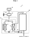
- FIG. 1 is a block diagram illustrating an example configuration of a water heater 1 according to Embodiment 1 of the present disclosure.
- the water heater 1 is a hot-water storage type water heater that includes a heat pump unit 10, a tank unit 20, and a remote controller 30.
- the water heater 1 autonomously performs a water-heating operation while alternately switching between high capacity (a first operation, more specifically a normal operation described further below) and a low capacity (a second operation, more specifically a suppressed operation described further below) each unit time. Also, multiple operation patterns for switching between the high capacity and the low capacity are defined. The water heater 1 determines one operation pattern in accordance with whether the pre-set number (for example, a serial number described further below) is even or odd, and performs a water-heating operation.
- the pre-set number for example, a serial number described further below
- the heat pump unit 10 is a heat pump that uses refrigerant such as CO2 or a hydrofluorocarbon (HFC).
- the heat pump unit 10 includes a compressor 11, a water-refrigerant heat exchanger 12, an expansion valve 13, an air heat exchanger 14, and a blower device 15.
- the compressor 11, the water-refrigerant heat exchanger 12, the expansion valve 13, and the air heat exchanger 14 are connected in a loop shape by piping and together form a refrigeration cycle circuit (refrigerant circuit) for circulating refrigerant.
- the compressor 11 raises the temperature and pressure by compressing the refrigerant.
- the compressor 11 includes an inverter circuit that can change a capacity (feed-out amount per unit) in accordance with a drive frequency.
- the water-refrigerant heat exchanger 12 is a heating source for heating municipal tap water until the water temperature elevates to a target water-heating temperature (hot water storage temperature).
- the water-refrigerant heat exchanger 12 is a plate-type or a double-pipe type heat exchanger that performs heat exchange between refrigerant and water (low temperature water). Through heat exchange in the water-refrigerant heat exchanger 12, heat dissipates from the refrigerant causing the temperature to decrease and the water absorbs heat causing the temperature to rise.
- the expansion valve 13 allows expansion of the refrigerant causing the pressure and temperature to rise.
- the air heat exchanger 14 performs heat-exchange between the refrigerant and outside air blown in by the blower device 15. Through heat-exchange by the air heat exchanger 14, the refrigerant absorbs heat causing the temperature of the refrigerant to rise, and heat from the outside air is released causing and the temperature of the refrigerant to decrease.
- the blower device 15 blows outside air to the air heat exchanger 14.
- the heat pump unit 10 includes a non-illustrated temperature sensor for measuring the outside air temperature for example.
- Such a heat pump unit 10 has a heating capacity that is proportional to power consumption, and this capacity is mainly controlled by controlling the frequency of the compressor 11. For example, a suppressed operation can be performed that suppress heating capacity and power consumption by suppressing the frequency of the compressor 11 to no greater than a certain frequency.
- the tank unit 20 includes a hot water tank 21, a water pump 22, a control board 23, and an indicator 24. These components are housed in, for example, an outer case made of metal (a portion of the indicator 24 is at the surface of the case).
- the hot water tank 21 is formed of a material such as metal (stainless steel, for example) or a resin. Insulation material (not illustrated) is disposed on an outer portion of the hot water tank 21. Therefore, the hot water in the hot water tank 21 can be maintained at a high temperature for a long period of time.
- the hot water tank 21, the water pump 22, and the water-refrigerant heat exchanger 12 of the heat pump unit 10 are connected to one another by piping, forming a water-heating circuit for circulating hot water from the lower portion of the hot water tank 21, via the water pump 22 and the water-refrigerant heat exchanger 12, back to the top portion of the hot water tank 21.
- the water pump 22 transfers low temperature water from the bottom portion of the hot water tank 21 to the water-refrigerant heat exchanger 12.
- the control board 23 includes, for example, a central processing unit (CPU), a read-only memory (ROM), a random-access memory (RAM), a communication interface, a readable/writable non-volatile semiconductor memory, all of which are not illustrated, and performs overall control of the water heater 1. Further below, the control board 23 is described in detail.
- CPU central processing unit
- ROM read-only memory
- RAM random-access memory
- communication interface a readable/writable non-volatile semiconductor memory, all of which are not illustrated, and performs overall control of the water heater 1. Further below, the control board 23 is described in detail.
- the indicator 24 includes, for example, an LED display and a liquid crystal display and displays, under the control of the control board 23, information regarding the water heater 1. Specifically, the indicator 24, as described further below, displays an operation pattern (pattern A or pattern B, for example) set to the water heater 1.
- the tank unit 20 includes a non-illustrated temperature sensor for measuring the water temperature (remaining hot water temperature and/or the water-heating temperature) in the hot water tank 21 and/or a non-illustrated hot water level gauge for measuring the remaining hot water amount in the hot water tank 21.
- the remote controller 30 includes, for example, an operating panel and a display, and is operated by a user.
- the remote controller 30 receives a manual operation performed by the user on the operating panel and notifies the control board 23 regarding the operation details.
- the display of the remote controller 30 displays, under the control of the control board 23, various sorts of information regarding the water heater 1.
- the display displays information such as the water-heating setting temperature, remaining hot water amount, and the operation status (also including the operation pattern set to the water heater 1 described further below).
- FIG. 2 is a block diagram illustrating an example configuration of the control board 23.
- the control board 23 includes a settings data storage 41, a past data storage 42, a pattern specifier 43, a heat amount calculator 44, a water-heating heat amount determiner 45, a water heating scheduler 46, a water heating controller 47, and a communicator 48.
- the functions of the pattern specifier 43, the heat amount calculator 44, and the water-heating heat amount determiner 45, the water heating scheduler 46, and the water heating controller 47 are achieved by the CPU's using the RAM as working memory and appropriately executing, for example, various types of programs stored in the ROM.
- the settings data storage 41 stores various types of settings data pertaining to the water heater 1.
- the settings data storage 41 stores a serial number unique to the water heater 1 and pattern information defining operation patterns.
- Various pre-determined patterns constitute the pattern information and the water-heating operation of the water heater 1 is controlled in accordance with one pattern of the pattern information.
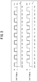
- the settings data storage 41 stores two types of pattern information (patterns A and B) as illustrated in FIG. 3 .
- the pattern information defines division of the late-night time period ((23:00 to 7:00) (24-hour time period), as one example) into segments of unit time (30 minutes, as one example) and switching between normal operation H (high capacity: 100% capacity) and suppressed operation L (low capacity: 50% capacity) each unit time.
- pattern A and pattern B are set such that the timing of normal operation H and the timing of suppressed operation L are different with respect to each other (such that the phases are inverted with respect to each other).
- Normal operation H and suppressed operation L may be described using different expressions. For example, normal operation H may be referred to as a first operation and suppressed operation L may be referred to as a second operation.
- pattern A is defined as an operation pattern in which normal operation H is performed from n o'clock to thirty minutes after n o'clock and suppressed operation L is performed from thirty minutes after n o'clock to (n + 1) o'clock.
- pattern B is defined as an operation pattern in which suppressed operation L is performed from n o'clock to thirty minutes after n o'clock and normal operation H is performed from thirty minutes after n o'clock to (n + 1) o'clock.
- normal operation H is indicated as being at 100% capacity
- suppressed operation L is indicated as being at 50% capacity. This is merely an example and can be modified as appropriate.
- the capacity of suppressed operation L may be modified from 40% capacity up to 50% capacity.
- the unit time is not limited to 30 minutes and may be modified as appropriate to, for example, 60 minutes or 45 minutes.
- the pattern information is not limited to these patterns A and B and as is described further below, the pattern information may contain other patterns.
- the past data storage 42 stores past usage heat amounts in the water heater 1.
- the past data storage 42 stores a cumulative usage heat amount (past data) being a two to four-week accumulation of daily heat usage heat amounts.
- the pattern specifier 43 retrieves a serial number and pattern information from the settings data storage 41 and specifies (determines) an operation pattern to be adopted by the water heater 1. For example, the pattern specifier 43 specifies the pattern operation to be pattern A when the serial number is an even number. Conversely, when the serial number is an odd number, the pattern specifier 43 specifies the operation pattern to be pattern B. This is an example method for specifying the operation pattern and may be modified as appropriate. For example, as described further below, the operation pattern to be adopted by the water heater 1 may be determined in accordance with even and odd numbers of a numerical value other than serial numbers.
- the heat amount calculator 44 retrieves past data (cumulative usage heat amount) from the past data storage 42 and calculates an average value of a usage heat amount in the water heater 1 for a single day. For example, the heat amount calculator 44 calculates an average usage heat amount Qave by dividing the cumulative usage heat amount by the cumulative number of days.
- the target heat amount Qo is obtained by equation 1 indicated below.
- Qo Qave ⁇ heat loss coefficient + start-up heat amount ⁇ nighttime rate
- the heat loss coefficient is a value (1.1, for example) accounting for heat dissipation from the hot water tank 21 until a user uses the hot water, with respect to a heat amount at which the heat pump unit 10 performed heating.
- the start-up heat amount is the tank heat amount condition (3500 kcal, for example) computed from the remaining hot water amount in the hot water tank 21 in a case where a hot water storage operation starts during a daytime period.
- the nighttime rate is a percentage (80%, for example) of power amount used during a late-night time period with respect to a power amount used over a 24-hour time period.
- the remaining hot water heat amount Qt is obtained from, for example, the current remaining hot water temperature acquired by the temperature sensor and/or remaining hot water amount acquired by the hot water amount gauge.
- the water heating scheduler 46 determines a water heating start time based on the operation pattern specified by the pattern specifier 43 and the hot-water heat amount as determined by the water-heating heat amount determiner 45, and establishes a control schedule from the start of water heating to the end of water heating. For example, the water heating scheduler 46 determines a water heating start time by going in reverse chronology from the end time (7:00, for example) of the late-night time period by the amount of time necessary to perform the water-heating operation.
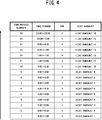
- the water heating scheduler 46 alternatingly cumulates, in reverse chronology from time period number 1 (6:30 to 7:00), the heat amounts during suppressed operation L and the heat amounts during normal operation H as in illustrated FIG. 4 . Then, when the cumulative heat amount exceeds the water-heating heat amount Qn, the water heating scheduler 46 sets the water heating start time to that particular time. In other words, the water heating scheduler 46 sets the water heating start time to the time at which the condition of "water-heating heat amount Qn ⁇ ⁇ (heat amount 1 to heat amount i)" is satisfied.
- the heat amount during suppressed operation L and the heat amount during normal operation H can be obtained in the manner described below.
- Heat amount kCal during suppressed operation L 860 cal / Wh ⁇ 3.0 kW ⁇ 0.5 h
- Heat amount kCal during normal operation H 860 cal / Wh ⁇ 6.0 kW ⁇ 0.5 h
- the capacity of suppressed operation L is variable at 5% increments from a capacity of 40% up to a capacity of 50% (the range of change and the increment size may be adjusted as appropriate).
- the capacity of suppressed operation L is variable at 5% increments from a capacity of 40% up to a capacity of 50% (the range of change and the increment size may be adjusted as appropriate).
- 2.4 [kW] is used, whereas in a case in which suppressed operation L is performed at 45%, 2.7 [kW] is used.
- One of the following methods is adopted if, the heat amount T does not exceed the water-heating heat amount Qn even when the heat amounts over the late-night time period back to the start time thereof are cumulated with the capacity of suppressed operation L increased to 50%.
- Method 1 The duration of the time of the late-night time period is extended either backward or forward in time or both backward and forward in time to keep water heating operation performing continuously under suppressed operation L at 50% capacity.
- Method 2 The water-heating operation is completed when the amount of hot water reaches the amount that can be produced during the late-night time period. Additional water heating is subsequently performed during the daytime in accordance with a midday usage amount to recover the amount of hot water used.
- the user is allowed to freely set (select) which one of these methods is to be adopted and the setting details are stored, for example, in the settings data storage 41.
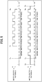
- the water heating scheduler 46 establishes a plan for performing a water heating operation from time T1 (1:00) to time Te (7:00) as illustrated in FIG. 5 .
- This plan following pattern A, starts water-heating operation at time T1 under normal operation H, and then alternately switches between normal operation H and suppressed operation L each unit time (30 minutes) until time Te.
- the water heating scheduler 46 establishes a plan for performing a water heating operation from time T2 (22:00) to time T3 (7:30) as illustrated in FIG. 5 .
- This example shows a case where the method 1 described above is used to address a situation in which the water heating is not completed by the end of the normal water-heating time period (late-night time period).
- the duration of time of the late-night time period is extended backward and forward in time.
- water-heating operation is performed under suppressed operation L at 50% capacity from time T2 to time Ts (23:00), then, from time Ts to time Te, water-heating operation is performed in accordance with pattern B, alternately switching between suppressed operation L and normal operation H, and then from time Te to time T3, water-heating operation is performed under suppressed operation at 50% capacity.
- the water heating controller 47 upon arrival of the water heating start time determined by the water heating scheduler 46, the water heating controller 47 performs a water-heating operation in accordance with the established plan (plan following the operation pattern specified by the pattern specifier 43).
- the water heating controller 47 transmits to the heat pump unit 10 a capacity control signal every 30 minutes (at n o'clock and at thirty minutes after n o'clock), and executes capacity control accordingly.
- a technique of controlling the revolution frequency of the compressor 11 is one specific example of capacity control of the heat pump unit 10.
- the pattern A based plan and the pattern B based plan as described above and illustrated in FIG. 5 define that the timing of normal operation H and the timing of suppressed operation L are different with respect to each other (such that the phases are inverted with respect to each other) during the late-night time period.
- the water heating controller 47 in each of the water heaters 1 can reduce the peak when performing the water heating control, by approximately 25% compared with conventional technology. Therefore, the peak power can be suppressed from arising in the entirety of a condominium or a region.
- the communicator 48 communicates with the remote controller 30 to receive manual operations from a user and to transmit information regarding the water heater 1.
- the communicator 48 as described further below may be capable of communicating with other devices such as a management device.
- FIG. 6 is a flowchart illustrating an example of water-heating operation processing that is executed by the control board 23.
- FIG. 7 is a flowchart illustrating details of start-time determination processing in FIG. 6 .
- the water-heating operation processing illustrated in FIG. 6 starts at a predetermined planning time.
- control board 23 acquires a serial number (step S101). That is, the pattern specifier 43 retrieves the unique serial number from the settings data storage 41.
- the control board 23 determines whether or not the serial number is an odd number (step S102). When the control board 23 determines that the serial number is an odd number (YES in step S102), the operation pattern is set to pattern A (step S103). Conversely, when the control board 23 determines that serial number is not an odd number (is an even number)) (NO in step S102), the control board 23 sets the operation pattern to pattern B (step S104).
- the control board 23 studies the past data (step S105). That is, the heat amount calculator 44 retrieves the past data (cumulative usage heat amount) from the past data storage 42 and calculates an average single-day usage heat amount value. For example, the heat amount calculator 44 calculates the average usage heat amount Qave by dividing the cumulative usage heat amount by the cumulative number of days.
- the control board 23 performs start-time determination processing (step S107). This start-time determination processing is executed as illustrated in FIG. 7 .
- the water heating scheduler 46 (control board 23) sets the capacity suppression value P to an initial value of 40% (step S201).
- This capacity suppression value P indicates the capacity during suppressed operation L.
- the water heating scheduler 46 sets the time period number N to an initial value of 1 and sets the heat amount T to an initial value of 0 (step S202).
- the time period number N indicates the aforementioned time period number illustrated in FIG. 4 and is used for going back in order from the end time of the late-night time period.
- the heat amount T indicates an accumulation of heat amounts that are cumulated in reverse chronology.
- the water heating scheduler 46 calculates the heat amount NT of a time period number N in the set operation pattern (step S203). In other words, if the operation for a time period number N is suppressed operation L, the water heating scheduler 46 calculates the heat amount during suppressed operation L. Conversely, if the operation for a time period number N is normal operation H, the water heating scheduler 46 calculates a heat amount during normal operation H.
- the water heating scheduler 46 increments the heat amount T by a heat amount NT in the time period number N (step S204).
- the water heating scheduler 46 determines whether or not the heat amount T exceeds the water-heating heat amount Qn (step S205). The water heating scheduler 46, as described above, obtains the water-heating heat amount Qn by subtracting the remaining heat amount Qt from the target heat amount Qo.
- the water heating scheduler 46 determines the start time to be the starting point of the time period number N (a leading time of time period number N) (step S206). The water heating scheduler 46 then ends the start time determination processing in FIG. 7 .
- the water heating scheduler 46 increments the time period number N by 1 (step S207).
- the water heating scheduler 46 determines whether or not the value of the time period number N exceeds 16 (step S208). That is, the water heating scheduler 46 determines whether or not the increment takes the time period of interest backward in time earlier than the start time (23:00) of the late-night time period.
- the water heating scheduler 46 When determining the value of the time period number N does not exceed the 16 (No in step S208), the water heating scheduler 46 returns processing to the aforementioned step S203.
- the water heating scheduler 46 determines whether or not the capacity suppression value P is 50% (step S209). That is, the water heating scheduler 46 determines whether an increase has been made to 50% being the upper limit during suppressed operation L.
- step S209 When determining that the capacity suppression value P is not 50% (No in step S209), the water heating scheduler 46 increments the capacity suppression value P by 5% (step S210). Then, processing is returned to aforementioned step S202.
- the water heating scheduler 46 determines whether or not time can be extended (step S211). In other words, the water heating scheduler 46 determines whether the settings data storage 41 stores the setting details that adopt the aforementioned method 1 in the case in which the heat amount T does not exceed the water-heating heat amount Qn even if the heat amounts over the late-night time period back to the start time thereof are cumulated with the capacity of suppressed operation L increased to 50%.
- the water heating scheduler 46 calculates the necessary time based on the insufficient heat amount, and determines the start time (step S212). The water heating scheduler 46 then ends the start-time determination processing of FIG. 7 .
- the water heating scheduler 46 determines the specific start time (step S213). For example, the water heating scheduler 46 determines the starting point (23:00, for example) of the late-night time period to be the start time. The water heating scheduler 46 then ends the start time determination processing of FIG. 7 .
- control board 23 remains in standby until the arrival of the determined start time (step S108). Specifically, the control board 23 compares the determined start time against the current time and withholds from executing subsequent processing when a determination is made that the arrival of the start time has yet to arrive (No in step S108).
- step S109 Upon arrival of the start time (Yes in step S108), the control board 23 performs the water-heating operation (step S109). That is, the water heating controller 47 performs the water-heating operation in accordance with the plan (plan following the operation patterns specified by the pattern specifier 43) established by the water heating scheduler 46.
- the control board 23 determines whether or not water heating is completed (step S110). In other words, the control board 23 determines whether or not water heating completion is detected. If the control board 23 determines that the water heating is not yet completed (No in step S110), then the control board 23 returns processing to the aforementioned step S109.
- control board 23 determines that the water heating is completed (Yes in step S110), then the control board 23 stops the operation (step Sill). The control board 23 then ends the water-heating operation processing.
- each of the water heaters 1 performs a water-heating operation while autonomously switching, in an alternating manner, between normal operation H and suppressed operation L each unit time.
- each of the water heaters 1 determines the operation pattern to be pattern A or pattern B in accordance with its own serial number (even or odd number), and performs the water heating operation accordingly.
- Embodiment 1 describes the case in which an operation pattern is determined to be pattern A or pattern B in accordance with specific serial numbers (even and odd numbers), but the operation pattern may be determined in accordance with another value.
- the settings data storage 41 may store in advance values set by an installation technician via the remote controller 30 so that the operation pattern is determined to be pattern A or pattern B in accordance with the values.
- the installation technician sets each water heater 1 with a value in accordance with an installation plan such that even and odd numbers are assigned in a substantially equal manner among the water heaters 1.
- the installation technician may set each water heater 1 with a value such as a room number, a floor number, a condominium building number and the like such that even and odd numbers are assigned in a substantially equal manner among the water heaters 1.
- the water heater 1 may be equipped with a dedicated switch and the operating pattern may be determined to be pattern A or pattern B depending on whether the dedicated switch is turned ON or OFF (ON setting corresponds to even numbers and OFF setting corresponds to odd numbers, for example).
- the installation technician performs settings based on an installation plan such that the ON settings and the OFF settings of the dedicated switches are assigned in a substantially equal manner among the water heaters 1.
- Embodiment 1 describes the case in which one of two patterns is determined as the operation pattern, an operation pattern may be determined from among other patterns in addition to pattern A and pattern B.
- an operation pattern may be determined to be a first-half pattern performed only during the first half of the late-night time period or a second-half pattern performed only during the second half of the late-night time period.
- the first-half pattern and the second-half pattern may also be determined in accordance with the specific serial numbers (even and odd numbers), set values (even and odd numbers), or a dedicated switch (ON and OFF).
- the second-half pattern is more advantageous than the first-half pattern, fixing of the patterns is not preferred. Therefore, as described further below, a determination is made such that the first-half pattern operation and the second-half pattern operation are rotated as appropriate.
- the water heating scheduler 46 establishes a plan to perform a water-heating operation from time Th (3:00) to time Te (7:00), as illustrated in FIG. 8 .
- water-heating operation starts under suppressed operation L from time Th and this operation continues as is until time T11, and then from time T11 to time Te the water-heating operation is performed under normal operation H.
- the water heating scheduler 46 establishes a plan to perform a water-heating operation from time Ts (23:00) to time Th as illustrated in FIG. 8 .
- water-heating operation starts under normal operation H from time Ts and this operation continues as is until T12, and then from time T12 to time Th water-heating operation is performed under suppressed operation L.
- the water heating scheduler 46 establishes a plan to perform a water-heating operation from time T13 (1:00) to time Te as illustrated in FIG. 8 .
- This plan, following pattern A, starts water-heating operation from time T13 under normal operation H alternately switching between normal operation H and suppressed operation L each unit time (30 minutes) until time Te.
- the water heating scheduler 46 establishes a plan to perform a water-heating operation from time Ts to time Te as illustrated in FIG. 8 .
- water-heating operation is performed in accordance with pattern B alternately switching between suppressed operation L and normal operation H until time Te.
- Such kind of a plan based on the second-half pattern and the first-half pattern stipulates that the operation times do not overlap with each other during the late-night time period. Also, as described above, the plan following pattern A and pattern B is set such that the timing of normal operation H and the timing of suppressed operation L are different from each other during the late-night time period. Therefore, the water heating controller 47 in each of the water heaters 1 (water heaters 1a, 1b, 1c, 1d, ...) can reduce the peak when performing water heating control. Therefore, the peak power can be suppressed from arising in the entirety of a condominium or a region.
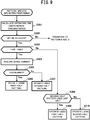
- FIG. 9 is a flowchart demonstrating an example of pattern-specific operation processing.
- control board 23 calculates the operation time under normal circumstances (step S301). That is, the operation time of a water-heating operation performed under normal operation H is calculated.
- the control board 23 determines whether or not the calculated operation time is within 3.5 hours (step S302). If the control board 23 determines that the operation time is not within 3.5 hours (exceeds 3.5 hours) (No in step S302), the operation transitions to non-illustrated patterns A and B.
- control board 23 determines whether or not the first-half pattern operation or the second-half pattern operation is to be performed for the first time (step S303).
- the control board 23 acquires the serial number (step S304). As previously described, a set value or a value of a dedicated switch may be acquired instead of the serial number.
- the control board 23 determines whether the serial number is an odd number (step S305). When determining that the serial number is an odd number (Yes in step S305), the control board 23 performs operation using the first-half pattern (step S306).
- control board 23 performs operation using the second-half pattern (step S307).
- step S303 when determining that the first-half pattern operation or the second-half pattern operation is to be performed for the first time (No in step S303), the control board 23 determines whether or not the most-recently executed pattern is the second-half pattern (step S308).
- control board 23 When determining that the second-half pattern is the most-recently executed pattern (Yes in step S308), the control board 23 performs the operation using the first-half pattern (step S309).
- control board 23 performs the operation using the second-half pattern (step S310).
- the pattern-specific operation processing causes the first-half pattern operation and the second-half pattern operation to rotate as appropriate.
- this pattern-specific operation processing an example is given in which one operate pattern of the first-half pattern or the second-half pattern is operated that is opposite to the other operation pattern executed last time, and the first-half pattern operation and the second-half pattern operation are rotated as appropriate.
- Another technique however may be used for appropriately rotating the first-half pattern operation and the second-half pattern operation.
- the first-half pattern operation and the second-half pattern operation may be appropriately rotated by determining the first-half pattern or the second-half pattern in accordance with even and odd numbers for that particular date (date of operation), for example.
- Embodiment 1 the operation of the water heater 1 as a stand-alone apparatus is described but the settings data of a plurality of water heaters 1 may be made to be settable (changeable).
- Embodiment 2 of the present disclosure is described.
- a configuration is such that settings can be appropriately performed on the water heaters 1 (water heaters 1a, 1b, 1c, 1d, ...) by taking into account the overall operation state of the water heaters 1.
- Each of the set water heaters 1 operates autonomously in accordance with the operation pattern in the manner described further above.
- FIG. 10 is a block diagram illustrating an example of a schematic configuration of a water heating system 50 according to Embodiment 2 of the present disclosure.
- a water heating system 50 includes an overall management device 51, a common-area management device 52, management devices 53 (management devices 53a, 53b, 53c, ...), and the water heaters 1 (water heaters 1a, 1b, 1c, 1c, 1d, ).
- the overall management device 51 is a Mansion (Condominium) Energy Management System (MEMS) that performs overall control of the water heating system 50.
- the overall management system 51 collects information from the common-area management device 52 and each of the management devices 53, and determines an operation pattern (either pattern A or B, for example) of the water heaters 1 on a per-water heater basis such that the overall peak can be reduced.
- the overall management device 51 notifies each of the water heaters 1 of the determined operation pattern, via the management device 53.
- the common-area management device 52 transmits to the overall management device 51 power information of devices to be used in common areas.
- the devices to be used in the common areas are not limited to devices that consume electricity and may therefore include devices that generate electricity such as photovoltaic power generator, and devices that discharge stored electricity such as a storage battery.
- the common-area management device 52 transmits to the overall management device 51 information regarding electricity consumed, information regarding generated (included forecasts) electricity, and information regarding electricity that is discharged, in the common areas of the condominium.
- the management device 53 is a Home Energy Management System (HEMS) controller that is installed in each living unit in the condominium.
- the management device 53 transmits to the overall management device 51 configuration information regarding the water heater 1 (water heater of in the same room) under charge.
- the configuration information is not limited to the number of water heaters 1 but also includes information regarding standards information and past data of the water heaters 1.
- the management device 53 receives an operation pattern determined by the overall management device 51 and transmits the operation pattern to the water heater 1 under charge.
- the water heater 1 Upon receiving the operation pattern, the water heater 1 executes a water-heating operation in accordance with the operation pattern.
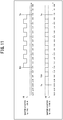
- the water heating controller 47 performs a water-heating operation from time T21 (1:00) to time Te (7:00), as illustrated in FIG. 11 .
- the water-heating operation in accordance with pattern A, starts from time T21 under normal operation H, and then alternately switches between normal operation H and suppressed operation L each unit time (30 minutes) until time Te.
- the water heating controller 47 performs a water-heating operation from time Ts (23:00) to time Te, as illustrated in FIG. 11 .
- the water heating controller 47 performs the water-heating operation is performed under normal operation H during this unused time until time T22 (0:00), and then time T22, from time Ts to time Te, a water-heating operation is performed in accordance with pattern B, switching in an alternating manner, between normal operation H and suppressed operation L until time Te.
- Such kind of a plan in accordance with pattern A and pattern B stipulates that the timing of normal operation H and suppressed the timing of suppressed operation L are different with respect to each other during the late-night time period.
- This plan stipulates that unused time during which other water heaters 1 are not operated can be utilized so that a water-heating operation can be performed under normal operation H. Therefore, the water heating controller 47 in each of the water heaters 1 (water heaters 1a, 1b, 1c, 1d, ...) can reduce the peak when performing water heating control. Therefore, the peak power can be suppressed from arising in the entirety of a condominium or a region.
- each of the water heaters 1 may be notified of a value such that even and odd numbers are assigned in a substantially equal manner, and the operation pattern of each of the water heaters 1 may be determined in accordance with the value (even number or odd number) as described in Embodiment 1.
- the programs executed by the control board 23 in the aforementioned embodiments may be stored in a computer-readable recording medium such as a compact disc read-only memory (CD-ROM), a digital versatile disc (DVD), a magneto-optical disk (MO), a universal serial bus (USB) memory, and a memory card, and distributed.
- a computer-readable recording medium such as a compact disc read-only memory (CD-ROM), a digital versatile disc (DVD), a magneto-optical disk (MO), a universal serial bus (USB) memory, and a memory card, and distributed.
- the above-described program may be stored on a disk device of a server device on a communication network, such as the Internet, to enable the program to be downloaded to the computer, for example by superimposing the program onto a carrier wave.
- the above-described processing can be achieved even by execution while the program is transferred through the communication network.
- the above-described processing can be achieved by executing all or part of the program on the server device, and executing the program while sending and receiving by the computer the information relating to such processing through the communication network.
- the non-OS portion alone may be stored in the above-described recording medium and distributed, or alternatively, may be, for example, downloaded to the computer.
- the present disclosure can be used with advantage for a water heater and a water heating system.
Landscapes
- Engineering & Computer Science (AREA)
- Physics & Mathematics (AREA)
- Thermal Sciences (AREA)
- Chemical & Material Sciences (AREA)
- Combustion & Propulsion (AREA)
- Mechanical Engineering (AREA)
- General Engineering & Computer Science (AREA)
- Computer Hardware Design (AREA)
- Power Engineering (AREA)
- Heat-Pump Type And Storage Water Heaters (AREA)
Claims (5)
- Chauffe-eau (1) de type à accumulation d'eau chaude comprenant :un moyen de stockage de données de réglage (41) configuré pour stocker un numéro de série unique au chauffe-eau (1) et des informations de configuration définissant une pluralité de configurations de fonctionnement ;un moyen de détermination de configuration (43) configuré pour récupérer le numéro de série et des informations de configuration à partir du moyen de stockage de données de réglage (41) et pour déterminer une configuration de fonctionnement de la pluralité de configurations de fonctionnement à adopter par le chauffe-eau (1) selon que le numéro de série est un nombre pair ou un nombre impair, la configuration de fonctionnement correspondant au numéro de série, la pluralité de configurations de fonctionnement comportant deux configurations de fonctionnement ayant chacune une synchronisation d'un premier fonctionnement et une synchronisation d'un deuxième fonctionnement, les deux configurations de fonctionnement ayant des synchronisations de fonctionnement différentes l'une de l'autre ;un moyen de détermination de quantité de chaleur (45) configuré pour déterminer une quantité de chaleur nécessaire pour le chauffage d'eau ;un moyen d'établissement de plan (46) configuré pour établir un plan de chauffage d'eau sur la base de la configuration de fonctionnement déterminée par le moyen de détermination de configuration (43) et de la quantité de chaleur de chauffage d'eau déterminée par le moyen de détermination de quantité de chaleur (45), etun moyen de commande (47) configuré pour réaliser un fonctionnement de chauffage d'eau commutant alternativement entre le premier fonctionnement et le deuxième fonctionnement sur la base du plan de chauffage d'eau établi par le moyen d'établissement de plan (46), le premier fonctionnement fonctionnant à une capacité élevée, le deuxième fonctionnement fonctionnant à une capacité inférieure à celle du premier fonctionnement.
- Chauffe-eau (1) selon la revendication 1, caractérisé en ce que le moyen de commande (47) est configuré pour commuter alternativement entre le premier fonctionnement et le deuxième fonctionnement à chaque unité de temps pour chauffer de l'eau.
- Chauffe-eau (1) selon la revendication 1, caractérisé en ce que, lorsqu'un plan de chauffage d'eau dans une période de temps prédéterminée de fin de nuit est établi, le moyen d'établissement de plan (46) est configuré pour changer une valeur de capacité du deuxième fonctionnement de sorte que le plan de chauffage d'eau soit achevé dans la période de temps de fin de nuit.
- Chauffe-eau (1) selon la revendication 1, caractérisé en ce que, lorsque la quantité de chaleur de chauffage d'eau déterminée par le moyen de détermination de quantité de chaleur (45) ne peut être obtenue que dans un délai prédéterminé par le premier plan de fonctionnement, le moyen d'établissement de plan (46) est configuré pour établir un plan de chauffage d'eau dans lequel le chauffage d'eau est réalisé dans une première moitié ou une deuxième moitié d'une période de temps prédéterminée de fin de nuit.
- Système de chauffage d'eau (50) comprenant :des chauffe-eaux (1a, 1b, 1c, 1d) de type à accumulation d'eau chaude tels que définis dans la revendication 1 ; etun dispositif de gestion globale (51) configuré pour gérer les chauffe-eaux (1a, 1b, 1c, 1d),dans lequelle dispositif de gestion globale (51) est configuré pour collecter des informations concernant chacun des chauffe-eaux (1a, 1b, 1c, 1d) et pour notifier à chacun des chauffe-eaux (1a, 1b, 1c, 1d) des informations pour attribuer une pluralité de configurations de fonctionnement de manière égale entre les chauffe-eaux (1a, 1b, 1c, 1d), etchacun des chauffe-eaux est configuré pour commuter alternativement entre un premier fonctionnement et un deuxième fonctionnement pour chauffer de l'eau conformément à une configuration de fonctionnement d'une pluralité de configurations de fonctionnement, la configuration de fonctionnement étant déterminée conformément aux informations envoyées sous forme de notification par le dispositif de gestion globale, le premier fonctionnement fonctionnant à une capacité élevée, le deuxième fonctionnement fonctionnant à une capacité inférieure à celle du premier fonctionnement.
Applications Claiming Priority (1)
| Application Number | Priority Date | Filing Date | Title |
|---|---|---|---|
| PCT/JP2015/083323 WO2017090168A1 (fr) | 2015-11-27 | 2015-11-27 | Unité et systeme d'alimentation en eau chaude |
Publications (3)
| Publication Number | Publication Date |
|---|---|
| EP3382297A1 EP3382297A1 (fr) | 2018-10-03 |
| EP3382297A4 EP3382297A4 (fr) | 2018-12-05 |
| EP3382297B1 true EP3382297B1 (fr) | 2021-08-04 |
Family
ID=58764024
Family Applications (1)
| Application Number | Title | Priority Date | Filing Date |
|---|---|---|---|
| EP15909285.7A Active EP3382297B1 (fr) | 2015-11-27 | 2015-11-27 | Unité et systeme d'alimentation en eau chaude |
Country Status (5)
| Country | Link |
|---|---|
| US (1) | US10876743B2 (fr) |
| EP (1) | EP3382297B1 (fr) |
| JP (1) | JP6584524B2 (fr) |
| CN (1) | CN108291738A (fr) |
| WO (1) | WO2017090168A1 (fr) |
Families Citing this family (6)
| Publication number | Priority date | Publication date | Assignee | Title |
|---|---|---|---|---|
| JP7005309B2 (ja) * | 2017-11-20 | 2022-01-21 | 三菱電機株式会社 | 貯湯式給湯装置 |
| CN110307652B (zh) * | 2019-06-27 | 2020-11-06 | 华帝股份有限公司 | 一种燃气热水器的控制方法 |
| CN111707004B (zh) * | 2020-05-25 | 2021-10-01 | 广东纽恩泰新能源科技发展有限公司 | 一种模块组合式空气源热泵机组控制系统 |
| NL2026436B1 (en) * | 2020-09-10 | 2022-05-09 | Eneco B V | Warm water supply arrangement |
| WO2022153199A1 (fr) * | 2021-01-14 | 2022-07-21 | Ariston S.P.A. | Système de chauffage ou de refroidissement à consommation adaptable |
| CN115875724B (zh) * | 2023-03-08 | 2023-04-28 | 河北思悟新能源科技有限公司 | 一种储热取暖器换热系统 |
Family Cites Families (24)
| Publication number | Priority date | Publication date | Assignee | Title |
|---|---|---|---|---|
| US4449178A (en) * | 1981-02-27 | 1984-05-15 | Fluidmaster, Inc. | Method and apparatus for controlled off peak load hot water heating |
| US4645908A (en) * | 1984-07-27 | 1987-02-24 | Uhr Corporation | Residential heating, cooling and energy management system |
| GB9122220D0 (en) * | 1991-10-19 | 1991-12-04 | Elia Paul | Hot water storage system |
| CN2421574Y (zh) * | 2000-02-14 | 2001-02-28 | 林茂森 | 一种调峰式电能转换储热空调器 |
| CN1117046C (zh) * | 2000-03-14 | 2003-08-06 | 山东省农业科学院土壤肥料研究所 | 可控量多功能固体二氧化碳气体肥料及其制备方法 |
| JP4951396B2 (ja) * | 2007-04-20 | 2012-06-13 | パナソニック株式会社 | 貯湯式給湯システムの運転方法と貯湯式給湯システム |
| JP2008267747A (ja) * | 2007-04-24 | 2008-11-06 | Chugoku Electric Power Co Inc:The | 温水供給システム |
| US8938311B2 (en) * | 2007-11-29 | 2015-01-20 | Daniel P. Flohr | Methods of remotely managing water heating units in a water heater |
| JP5256052B2 (ja) * | 2009-01-14 | 2013-08-07 | 一般財団法人電力中央研究所 | 電力負荷制御装置、電力負荷制御方法および電力負荷制御プログラム |
| US8422870B2 (en) * | 2009-02-13 | 2013-04-16 | General Electric Company | Residential heat pump water heater |
| JP5185351B2 (ja) * | 2010-11-01 | 2013-04-17 | 三菱電機株式会社 | 給湯機制御システム、給湯機制御装置、給湯機制御方法、およびプログラム |
| JP5789748B2 (ja) * | 2010-12-17 | 2015-10-07 | パナソニックIpマネジメント株式会社 | 給湯システム |
| JP5025835B2 (ja) * | 2010-12-27 | 2012-09-12 | パナソニック株式会社 | 運転計画方法、及びヒートポンプ式給湯暖房システムの運転方法 |
| JP5810970B2 (ja) * | 2012-02-28 | 2015-11-11 | 株式会社デンソー | 給湯制御システム |
| EP2873931B1 (fr) * | 2012-06-25 | 2017-10-18 | Mitsubishi Electric Corporation | Système d'alimentation en eau chaude |
| JP2014119217A (ja) * | 2012-12-18 | 2014-06-30 | Daikin Ind Ltd | 温熱機器 |
| JP5751247B2 (ja) * | 2012-12-27 | 2015-07-22 | ダイキン工業株式会社 | 給湯制御システム |
| JP5538574B2 (ja) * | 2013-01-17 | 2014-07-02 | 三菱電機株式会社 | 給湯機制御装置 |
| JP6127265B2 (ja) * | 2013-01-18 | 2017-05-17 | パナソニックIpマネジメント株式会社 | 貯湯式給湯装置 |
| JP6056671B2 (ja) * | 2013-06-11 | 2017-01-11 | 三菱電機株式会社 | 貯湯式給湯機 |
| JP5812043B2 (ja) * | 2013-06-19 | 2015-11-11 | 三菱電機株式会社 | 貯湯式給湯システム |
| JP6191531B2 (ja) * | 2014-04-17 | 2017-09-06 | 三菱電機株式会社 | 貯湯式給湯機 |
| CN104482654B (zh) * | 2014-11-14 | 2017-06-13 | 广东电网有限责任公司电力科学研究院 | 基于温控负荷电热水器的需求侧响应控制方法及其系统 |
| CN105004061A (zh) * | 2015-07-20 | 2015-10-28 | 国网天津市电力公司 | 一种电热水器错峰调参控制系统及其负荷管理的方法 |
-
2015
- 2015-11-27 JP JP2017552623A patent/JP6584524B2/ja active Active
- 2015-11-27 US US15/758,811 patent/US10876743B2/en active Active
- 2015-11-27 WO PCT/JP2015/083323 patent/WO2017090168A1/fr unknown
- 2015-11-27 EP EP15909285.7A patent/EP3382297B1/fr active Active
- 2015-11-27 CN CN201580084716.7A patent/CN108291738A/zh active Pending
Non-Patent Citations (1)
| Title |
|---|
| None * |
Also Published As
| Publication number | Publication date |
|---|---|
| JPWO2017090168A1 (ja) | 2018-03-29 |
| EP3382297A1 (fr) | 2018-10-03 |
| US10876743B2 (en) | 2020-12-29 |
| JP6584524B2 (ja) | 2019-10-02 |
| US20190086102A1 (en) | 2019-03-21 |
| CN108291738A (zh) | 2018-07-17 |
| WO2017090168A1 (fr) | 2017-06-01 |
| EP3382297A4 (fr) | 2018-12-05 |
Similar Documents
| Publication | Publication Date | Title |
|---|---|---|
| EP3382297B1 (fr) | Unité et systeme d'alimentation en eau chaude | |
| EP2660942B1 (fr) | Procédé de planification du fonctionnement | |
| EP2639922B1 (fr) | Procédé de planification de fonctionnement et dispositif de planification de fonctionnement | |
| US20170324246A1 (en) | Control apparatus, control system, control method, and program | |
| JP5185351B2 (ja) | 給湯機制御システム、給湯機制御装置、給湯機制御方法、およびプログラム | |
| JP5808084B2 (ja) | 設定表示端末 | |
| EP2741521A1 (fr) | Appareil de commande et procédé de commande pour des appareils électriques | |
| US11371722B2 (en) | Hot-water supply system, water heater, and control method for water heater | |
| KR20170102862A (ko) | 열병합 발전 방법 및 장치 | |
| EP2818801B1 (fr) | Procédé et dispositif permettant de commander des dispositifs de chauffage | |
| JP5538574B2 (ja) | 給湯機制御装置 | |
| JP5905682B2 (ja) | 給湯制御装置 | |
| CN108369028B (zh) | 控制装置、热水器的控制方法和记录介质 | |
| JP6074868B2 (ja) | 負荷制御システム、負荷制御装置、負荷制御方法 | |
| JP7142216B2 (ja) | 給湯装置及び給湯システム | |
| EP2829825B1 (fr) | Procédé pour commander un système de chauffage et système de chauffage | |
| EP3508799B1 (fr) | Système de commande d'alimentation en eau chaude, serveur, procédé de commande d'alimentation en eau chaude et programme | |
| JP7475508B2 (ja) | 給湯システム、クラウドサーバ、沸上げスケジュール管理方法及びプログラム | |
| JP2014222396A (ja) | 管理装置、機器管理方法、管理システム | |
| EP2843325B1 (fr) | Procédé de commande pour système de chauffage et système de chauffage | |
| WO2017009912A1 (fr) | Dispositif de gestion d'énergie, procédé de gestion d'énergie et programme | |
| JP6719672B2 (ja) | 制御装置、電力管理システム、情報提示方法及びプログラム | |
| JP7378251B2 (ja) | 制御装置、エネルギー管理システム、エネルギー管理方法及びプログラム | |
| JP2023117206A (ja) | 貯湯式給湯装置 | |
| WO2020017035A1 (fr) | Dispositif de commande, système de commande, procédé de commande et programme |
Legal Events
| Date | Code | Title | Description |
|---|---|---|---|
| STAA | Information on the status of an ep patent application or granted ep patent |
Free format text: STATUS: THE INTERNATIONAL PUBLICATION HAS BEEN MADE |
|
| PUAI | Public reference made under article 153(3) epc to a published international application that has entered the european phase |
Free format text: ORIGINAL CODE: 0009012 |
|
| STAA | Information on the status of an ep patent application or granted ep patent |
Free format text: STATUS: REQUEST FOR EXAMINATION WAS MADE |
|
| 17P | Request for examination filed |
Effective date: 20180322 |
|
| AK | Designated contracting states |
Kind code of ref document: A1 Designated state(s): AL AT BE BG CH CY CZ DE DK EE ES FI FR GB GR HR HU IE IS IT LI LT LU LV MC MK MT NL NO PL PT RO RS SE SI SK SM TR |
|
| AX | Request for extension of the european patent |
Extension state: BA ME |
|
| REG | Reference to a national code |
Ref country code: DE Ref legal event code: R079 Ref document number: 602015072088 Country of ref document: DE Free format text: PREVIOUS MAIN CLASS: F24H0001000000 Ipc: F24H0004040000 |
|
| A4 | Supplementary search report drawn up and despatched |
Effective date: 20181106 |
|
| RIC1 | Information provided on ipc code assigned before grant |
Ipc: F24D 17/02 20060101ALI20181030BHEP Ipc: F24H 9/20 20060101ALI20181030BHEP Ipc: G01K 17/06 20060101ALI20181030BHEP Ipc: F24H 4/04 20060101AFI20181030BHEP Ipc: F24D 19/10 20060101ALI20181030BHEP Ipc: G06Q 50/06 20120101ALI20181030BHEP |
|
| DAV | Request for validation of the european patent (deleted) | ||
| DAX | Request for extension of the european patent (deleted) | ||
| STAA | Information on the status of an ep patent application or granted ep patent |
Free format text: STATUS: EXAMINATION IS IN PROGRESS |
|
| 17Q | First examination report despatched |
Effective date: 20200127 |
|
| STAA | Information on the status of an ep patent application or granted ep patent |
Free format text: STATUS: EXAMINATION IS IN PROGRESS |
|
| GRAP | Despatch of communication of intention to grant a patent |
Free format text: ORIGINAL CODE: EPIDOSNIGR1 |
|
| STAA | Information on the status of an ep patent application or granted ep patent |
Free format text: STATUS: GRANT OF PATENT IS INTENDED |
|
| INTG | Intention to grant announced |
Effective date: 20210225 |
|
| GRAS | Grant fee paid |
Free format text: ORIGINAL CODE: EPIDOSNIGR3 |
|
| GRAA | (expected) grant |
Free format text: ORIGINAL CODE: 0009210 |
|
| STAA | Information on the status of an ep patent application or granted ep patent |
Free format text: STATUS: THE PATENT HAS BEEN GRANTED |
|
| AK | Designated contracting states |
Kind code of ref document: B1 Designated state(s): AL AT BE BG CH CY CZ DE DK EE ES FI FR GB GR HR HU IE IS IT LI LT LU LV MC MK MT NL NO PL PT RO RS SE SI SK SM TR |
|
| REG | Reference to a national code |
Ref country code: GB Ref legal event code: FG4D |
|
| REG | Reference to a national code |
Ref country code: AT Ref legal event code: REF Ref document number: 1417361 Country of ref document: AT Kind code of ref document: T Effective date: 20210815 |
|
| REG | Reference to a national code |
Ref country code: CH Ref legal event code: EP |
|
| REG | Reference to a national code |
Ref country code: DE Ref legal event code: R096 Ref document number: 602015072088 Country of ref document: DE |
|
| REG | Reference to a national code |
Ref country code: IE Ref legal event code: FG4D |
|
| REG | Reference to a national code |
Ref country code: LT Ref legal event code: MG9D |
|
| REG | Reference to a national code |
Ref country code: NL Ref legal event code: MP Effective date: 20210804 |
|
| REG | Reference to a national code |
Ref country code: AT Ref legal event code: MK05 Ref document number: 1417361 Country of ref document: AT Kind code of ref document: T Effective date: 20210804 |
|
| PG25 | Lapsed in a contracting state [announced via postgrant information from national office to epo] |
Ref country code: LT Free format text: LAPSE BECAUSE OF FAILURE TO SUBMIT A TRANSLATION OF THE DESCRIPTION OR TO PAY THE FEE WITHIN THE PRESCRIBED TIME-LIMIT Effective date: 20210804 Ref country code: AT Free format text: LAPSE BECAUSE OF FAILURE TO SUBMIT A TRANSLATION OF THE DESCRIPTION OR TO PAY THE FEE WITHIN THE PRESCRIBED TIME-LIMIT Effective date: 20210804 Ref country code: BG Free format text: LAPSE BECAUSE OF FAILURE TO SUBMIT A TRANSLATION OF THE DESCRIPTION OR TO PAY THE FEE WITHIN THE PRESCRIBED TIME-LIMIT Effective date: 20211104 Ref country code: PT Free format text: LAPSE BECAUSE OF FAILURE TO SUBMIT A TRANSLATION OF THE DESCRIPTION OR TO PAY THE FEE WITHIN THE PRESCRIBED TIME-LIMIT Effective date: 20211206 Ref country code: NO Free format text: LAPSE BECAUSE OF FAILURE TO SUBMIT A TRANSLATION OF THE DESCRIPTION OR TO PAY THE FEE WITHIN THE PRESCRIBED TIME-LIMIT Effective date: 20211104 Ref country code: ES Free format text: LAPSE BECAUSE OF FAILURE TO SUBMIT A TRANSLATION OF THE DESCRIPTION OR TO PAY THE FEE WITHIN THE PRESCRIBED TIME-LIMIT Effective date: 20210804 Ref country code: FI Free format text: LAPSE BECAUSE OF FAILURE TO SUBMIT A TRANSLATION OF THE DESCRIPTION OR TO PAY THE FEE WITHIN THE PRESCRIBED TIME-LIMIT Effective date: 20210804 Ref country code: SE Free format text: LAPSE BECAUSE OF FAILURE TO SUBMIT A TRANSLATION OF THE DESCRIPTION OR TO PAY THE FEE WITHIN THE PRESCRIBED TIME-LIMIT Effective date: 20210804 Ref country code: RS Free format text: LAPSE BECAUSE OF FAILURE TO SUBMIT A TRANSLATION OF THE DESCRIPTION OR TO PAY THE FEE WITHIN THE PRESCRIBED TIME-LIMIT Effective date: 20210804 Ref country code: HR Free format text: LAPSE BECAUSE OF FAILURE TO SUBMIT A TRANSLATION OF THE DESCRIPTION OR TO PAY THE FEE WITHIN THE PRESCRIBED TIME-LIMIT Effective date: 20210804 |
|
| PG25 | Lapsed in a contracting state [announced via postgrant information from national office to epo] |
Ref country code: PL Free format text: LAPSE BECAUSE OF FAILURE TO SUBMIT A TRANSLATION OF THE DESCRIPTION OR TO PAY THE FEE WITHIN THE PRESCRIBED TIME-LIMIT Effective date: 20210804 Ref country code: LV Free format text: LAPSE BECAUSE OF FAILURE TO SUBMIT A TRANSLATION OF THE DESCRIPTION OR TO PAY THE FEE WITHIN THE PRESCRIBED TIME-LIMIT Effective date: 20210804 Ref country code: GR Free format text: LAPSE BECAUSE OF FAILURE TO SUBMIT A TRANSLATION OF THE DESCRIPTION OR TO PAY THE FEE WITHIN THE PRESCRIBED TIME-LIMIT Effective date: 20211105 |
|
| PG25 | Lapsed in a contracting state [announced via postgrant information from national office to epo] |
Ref country code: NL Free format text: LAPSE BECAUSE OF FAILURE TO SUBMIT A TRANSLATION OF THE DESCRIPTION OR TO PAY THE FEE WITHIN THE PRESCRIBED TIME-LIMIT Effective date: 20210804 |
|
| PG25 | Lapsed in a contracting state [announced via postgrant information from national office to epo] |
Ref country code: DK Free format text: LAPSE BECAUSE OF FAILURE TO SUBMIT A TRANSLATION OF THE DESCRIPTION OR TO PAY THE FEE WITHIN THE PRESCRIBED TIME-LIMIT Effective date: 20210804 |
|
| REG | Reference to a national code |
Ref country code: DE Ref legal event code: R097 Ref document number: 602015072088 Country of ref document: DE |
|
| PG25 | Lapsed in a contracting state [announced via postgrant information from national office to epo] |
Ref country code: SM Free format text: LAPSE BECAUSE OF FAILURE TO SUBMIT A TRANSLATION OF THE DESCRIPTION OR TO PAY THE FEE WITHIN THE PRESCRIBED TIME-LIMIT Effective date: 20210804 Ref country code: SK Free format text: LAPSE BECAUSE OF FAILURE TO SUBMIT A TRANSLATION OF THE DESCRIPTION OR TO PAY THE FEE WITHIN THE PRESCRIBED TIME-LIMIT Effective date: 20210804 Ref country code: RO Free format text: LAPSE BECAUSE OF FAILURE TO SUBMIT A TRANSLATION OF THE DESCRIPTION OR TO PAY THE FEE WITHIN THE PRESCRIBED TIME-LIMIT Effective date: 20210804 Ref country code: EE Free format text: LAPSE BECAUSE OF FAILURE TO SUBMIT A TRANSLATION OF THE DESCRIPTION OR TO PAY THE FEE WITHIN THE PRESCRIBED TIME-LIMIT Effective date: 20210804 Ref country code: CZ Free format text: LAPSE BECAUSE OF FAILURE TO SUBMIT A TRANSLATION OF THE DESCRIPTION OR TO PAY THE FEE WITHIN THE PRESCRIBED TIME-LIMIT Effective date: 20210804 Ref country code: AL Free format text: LAPSE BECAUSE OF FAILURE TO SUBMIT A TRANSLATION OF THE DESCRIPTION OR TO PAY THE FEE WITHIN THE PRESCRIBED TIME-LIMIT Effective date: 20210804 |
|
| PLBE | No opposition filed within time limit |
Free format text: ORIGINAL CODE: 0009261 |
|
| STAA | Information on the status of an ep patent application or granted ep patent |
Free format text: STATUS: NO OPPOSITION FILED WITHIN TIME LIMIT |
|
| PG25 | Lapsed in a contracting state [announced via postgrant information from national office to epo] |
Ref country code: MC Free format text: LAPSE BECAUSE OF FAILURE TO SUBMIT A TRANSLATION OF THE DESCRIPTION OR TO PAY THE FEE WITHIN THE PRESCRIBED TIME-LIMIT Effective date: 20210804 |
|
| REG | Reference to a national code |
Ref country code: CH Ref legal event code: PL |
|
| 26N | No opposition filed |
Effective date: 20220506 |
|
| PG25 | Lapsed in a contracting state [announced via postgrant information from national office to epo] |
Ref country code: LU Free format text: LAPSE BECAUSE OF NON-PAYMENT OF DUE FEES Effective date: 20211127 Ref country code: IT Free format text: LAPSE BECAUSE OF FAILURE TO SUBMIT A TRANSLATION OF THE DESCRIPTION OR TO PAY THE FEE WITHIN THE PRESCRIBED TIME-LIMIT Effective date: 20210804 Ref country code: BE Free format text: LAPSE BECAUSE OF NON-PAYMENT OF DUE FEES Effective date: 20211130 |
|
| REG | Reference to a national code |
Ref country code: BE Ref legal event code: MM Effective date: 20211130 |
|
| PG25 | Lapsed in a contracting state [announced via postgrant information from national office to epo] |
Ref country code: SI Free format text: LAPSE BECAUSE OF FAILURE TO SUBMIT A TRANSLATION OF THE DESCRIPTION OR TO PAY THE FEE WITHIN THE PRESCRIBED TIME-LIMIT Effective date: 20210804 |
|
| PG25 | Lapsed in a contracting state [announced via postgrant information from national office to epo] |
Ref country code: IE Free format text: LAPSE BECAUSE OF NON-PAYMENT OF DUE FEES Effective date: 20211127 |
|
| PG25 | Lapsed in a contracting state [announced via postgrant information from national office to epo] |
Ref country code: HU Free format text: LAPSE BECAUSE OF FAILURE TO SUBMIT A TRANSLATION OF THE DESCRIPTION OR TO PAY THE FEE WITHIN THE PRESCRIBED TIME-LIMIT; INVALID AB INITIO Effective date: 20151127 |
|
| P01 | Opt-out of the competence of the unified patent court (upc) registered |
Effective date: 20230512 |
|
| PG25 | Lapsed in a contracting state [announced via postgrant information from national office to epo] |
Ref country code: CY Free format text: LAPSE BECAUSE OF FAILURE TO SUBMIT A TRANSLATION OF THE DESCRIPTION OR TO PAY THE FEE WITHIN THE PRESCRIBED TIME-LIMIT Effective date: 20210804 |
|
| PG25 | Lapsed in a contracting state [announced via postgrant information from national office to epo] |
Ref country code: LI Free format text: LAPSE BECAUSE OF NON-PAYMENT OF DUE FEES Effective date: 20220630 Ref country code: CH Free format text: LAPSE BECAUSE OF NON-PAYMENT OF DUE FEES Effective date: 20220630 |
|
| PGFP | Annual fee paid to national office [announced via postgrant information from national office to epo] |
Ref country code: FR Payment date: 20230929 Year of fee payment: 9 |
|
| PGFP | Annual fee paid to national office [announced via postgrant information from national office to epo] |
Ref country code: GB Payment date: 20231006 Year of fee payment: 9 |
|
| PGFP | Annual fee paid to national office [announced via postgrant information from national office to epo] |
Ref country code: DE Payment date: 20230929 Year of fee payment: 9 |
|
| REG | Reference to a national code |
Ref country code: DE Ref legal event code: R084 Ref document number: 602015072088 Country of ref document: DE |
|
| PG25 | Lapsed in a contracting state [announced via postgrant information from national office to epo] |
Ref country code: MK Free format text: LAPSE BECAUSE OF FAILURE TO SUBMIT A TRANSLATION OF THE DESCRIPTION OR TO PAY THE FEE WITHIN THE PRESCRIBED TIME-LIMIT Effective date: 20210804 |