EP3379102B1 - Anschlagstopper und puffer - Google Patents
Anschlagstopper und puffer Download PDFInfo
- Publication number
- EP3379102B1 EP3379102B1 EP16866015.7A EP16866015A EP3379102B1 EP 3379102 B1 EP3379102 B1 EP 3379102B1 EP 16866015 A EP16866015 A EP 16866015A EP 3379102 B1 EP3379102 B1 EP 3379102B1
- Authority
- EP
- European Patent Office
- Prior art keywords
- stopper
- plate
- bump
- shaped part
- collar
- Prior art date
- Legal status (The legal status is an assumption and is not a legal conclusion. Google has not performed a legal analysis and makes no representation as to the accuracy of the status listed.)
- Active
Links
Images


Classifications
-
- F—MECHANICAL ENGINEERING; LIGHTING; HEATING; WEAPONS; BLASTING
- F16—ENGINEERING ELEMENTS AND UNITS; GENERAL MEASURES FOR PRODUCING AND MAINTAINING EFFECTIVE FUNCTIONING OF MACHINES OR INSTALLATIONS; THERMAL INSULATION IN GENERAL
- F16F—SPRINGS; SHOCK-ABSORBERS; MEANS FOR DAMPING VIBRATION
- F16F9/00—Springs, vibration-dampers, shock-absorbers, or similarly-constructed movement-dampers using a fluid or the equivalent as damping medium
- F16F9/32—Details
- F16F9/58—Stroke limiting stops, e.g. arranged on the piston rod outside the cylinder
-
- F—MECHANICAL ENGINEERING; LIGHTING; HEATING; WEAPONS; BLASTING
- F16—ENGINEERING ELEMENTS AND UNITS; GENERAL MEASURES FOR PRODUCING AND MAINTAINING EFFECTIVE FUNCTIONING OF MACHINES OR INSTALLATIONS; THERMAL INSULATION IN GENERAL
- F16F—SPRINGS; SHOCK-ABSORBERS; MEANS FOR DAMPING VIBRATION
- F16F9/00—Springs, vibration-dampers, shock-absorbers, or similarly-constructed movement-dampers using a fluid or the equivalent as damping medium
- F16F9/32—Details
- F16F9/3207—Constructional features
- F16F9/3221—Constructional features of piston rods
-
- F—MECHANICAL ENGINEERING; LIGHTING; HEATING; WEAPONS; BLASTING
- F16—ENGINEERING ELEMENTS AND UNITS; GENERAL MEASURES FOR PRODUCING AND MAINTAINING EFFECTIVE FUNCTIONING OF MACHINES OR INSTALLATIONS; THERMAL INSULATION IN GENERAL
- F16F—SPRINGS; SHOCK-ABSORBERS; MEANS FOR DAMPING VIBRATION
- F16F9/00—Springs, vibration-dampers, shock-absorbers, or similarly-constructed movement-dampers using a fluid or the equivalent as damping medium
- F16F9/32—Details
- F16F9/3207—Constructional features
- F16F9/3235—Constructional features of cylinders
- F16F9/3242—Constructional features of cylinders of cylinder ends, e.g. caps
-
- F—MECHANICAL ENGINEERING; LIGHTING; HEATING; WEAPONS; BLASTING
- F16—ENGINEERING ELEMENTS AND UNITS; GENERAL MEASURES FOR PRODUCING AND MAINTAINING EFFECTIVE FUNCTIONING OF MACHINES OR INSTALLATIONS; THERMAL INSULATION IN GENERAL
- F16F—SPRINGS; SHOCK-ABSORBERS; MEANS FOR DAMPING VIBRATION
- F16F9/00—Springs, vibration-dampers, shock-absorbers, or similarly-constructed movement-dampers using a fluid or the equivalent as damping medium
- F16F9/32—Details
- F16F9/36—Special sealings, including sealings or guides for piston-rods
- F16F9/362—Combination of sealing and guide arrangements for piston rods
-
- F—MECHANICAL ENGINEERING; LIGHTING; HEATING; WEAPONS; BLASTING
- F16—ENGINEERING ELEMENTS AND UNITS; GENERAL MEASURES FOR PRODUCING AND MAINTAINING EFFECTIVE FUNCTIONING OF MACHINES OR INSTALLATIONS; THERMAL INSULATION IN GENERAL
- F16F—SPRINGS; SHOCK-ABSORBERS; MEANS FOR DAMPING VIBRATION
- F16F9/00—Springs, vibration-dampers, shock-absorbers, or similarly-constructed movement-dampers using a fluid or the equivalent as damping medium
- F16F9/32—Details
- F16F9/36—Special sealings, including sealings or guides for piston-rods
- F16F9/366—Special sealings, including sealings or guides for piston-rods functioning as guide only, e.g. bushings
-
- B—PERFORMING OPERATIONS; TRANSPORTING
- B60—VEHICLES IN GENERAL
- B60G—VEHICLE SUSPENSION ARRANGEMENTS
- B60G5/00—Resilient suspensions for a set of tandem wheels or axles having interrelated movements
Definitions
- the present invention relates to a bump stopper, and a shock absorber comprising the bump stopper.
- US 4 795 010 A discloses a hydraulic damper which is provided with a bum stopper.
- Said bum stopper comprises a bump cap fitted on and fixedly secured to a packing cap which is, in turn, fitted on and fixedly secured to one end of a cylinder main body the damper.
- Said bum stopper further comprises a bump plate assembly including a bump plate for directly abutting a bump rubber and a plate cap integrally connected to said bump plate.
- a bump stopper that absorbs shocks generated during maximum contraction of a shock absorber is also known from JP 4048083 B2 and JP H09 317811 A .
- the bump stoppers disclosed in JP 4048083 B2 and JP H09 317811 A are mounted on an end of a cylinder body into which a piston rod is movably inserted, or mounted on an end of an outer tube that accommodates a cylinder body. Shocks during maximum contraction of the piston rod are absorbed by the bump stopper and a bump cushion provided to the top end of the piston rod.
- the bump stopper disclosed in JP 4048083 B2 includes the following: a horizontal plate that receives a bump cushion; a folded part that extends downwards from the horizontal plate and is folded; and a communication hole formed in the folded part.
- An insertion hole into which the piston rod is inserted is provided to the center of the horizontal plate.
- the folded part is disposed on an end of a cylinder body in a state in which the piston rod is inserted into the insertion hole of the horizontal plate, and the folded part secures a space between the horizontal plate and the cylinder body. Muddy water and dust that have flowed into this space from a gap between the horizontal plate and the piston rod is discharged to the outside of the bump stopper via the communication hole of the folded part.
- JP H09 317811 A discloses a disc-shaped bump stopper.
- a protrusion is formed on the bottom surface of the disc-shaped bump stopper.
- the distal end of the protrusion is welded to a caulked part of an outer tube of a shock absorber, and a space is secured between a flat plate of the bump stopper and the caulked part by the protrusion. Dust that has flowed into this space from a gap between the bump stopper and a piston rod is discharged via a passage formed on the bottom surface of the flat plate.
- Document US 2009/194379 discloses a bump stopper which is considered the closest prior art.
- the folded part is formed by folding a pipe material or a flat plate by press machining.
- the folding angle is large (about 180 degrees), and thus cracks can easily form in the folded part when folding the pipe material or flat plate. Consequently, the manufacturing of such a bump stopper requires advanced technology.
- the protrusion is formed by depressing a portion of the top surface of the flat plate. Therefore, the bump stopper can easily be deformed back to its original flat plate shape having no protrusion or recess when the shock absorber contracts to the maximum degree and receives a shock from the bump cushion, and thus the bump stopper may not have sufficient strength.
- the bump stoppers disclosed in JP 4048083 B2 and JP H09 317811 A have a complex shape due to the folded part or the protrusion, and thus these bump stoppers are not only difficult to manufacture but also may not have sufficient strength.
- An object of the present invention is to provide a bump stopper that is easy to manufacture and has sufficient strength.
- a bump stopper for absorbing shocks generated during maximum contraction of a shock absorber in cooperation with a bump cushion
- the bump stopper comprising: a cap including a plate-shaped part having a rod hole into which a piston rod of the shock absorber may be inserted, and a cylindrical part configured to receive a portion of a cylinder of the shock absorber; a stopper provided to the plate-shaped part, the stopper being configured to receive the bump cushion; and a collar provided to the plate-shaped part configured so that it opposes the cylinder in an assembled state, wherein the collar comprises a plurality of support parts arranged in a radial manner on the plate-shaped part, the plurality of support parts being configured to support the plate-shaped part, a passage is formed by the cap and the collar, the passage being configured to allow the rod hole to communicate with an outside of the cylindrical part via an inside of the cylindrical part, and the passage is formed between the adjacent support parts.
- the shock absorber 1 is provided, for example, between a vehicle body 5 and a wheel shaft (not illustrated) of a vehicle, and generates a damping force to suppress vibrations of the vehicle body 5.
- the shock absorber 1 includes a cylinder 10 in which hydraulic oil is sealed, and a piston rod 30 inserted into the cylinder 10 such that the piston rod 30 can move into and out of the cylinder 10.
- a piston (not illustrated) is slidably accommodated in the cylinder 10, and one end of the piston rod 30 is connected to the piston.
- the inside of the cylinder 10 is partitioned by the piston into an extension-side chamber 11 and a contraction-side chamber (not illustrated).
- the cylinder 10 includes the following: an approximately cylindrical tube 12; a rod guide 13 provided to one end of the tube 12; and an oil seal 14.
- the rod guide 13 and the oil seal 14 are fixed to the tube 12 by bending the end of the tube 12 toward the inside.
- the rod guide 13 is formed in an annular shape, and a bush 15 is provided to the inner periphery of the rod guide 13.
- the piston rod 30 is slidably supported by the rod guide 13 via the bush 15.
- the oil seal 14 includes an annular base metal 14a, and lips 14b, 14c provided to the inner periphery of the base metal 14a.
- the lips 14b, 14c are joined to the base metal 14a by vulcanization adhesion.
- the lip 14b slidingly contacts the piston rod 30, and prevents hydraulic oil within the cylinder 10 from leaking to the outside.
- the lip 14c slidingly contacts the piston rod 30, and prevents foreign contaminants from flowing into the cylinder 10.
- a male screw 31 is formed on the other end of the piston rod 30.
- a nut (not illustrated) threadably engages with the male screw 31 in a state in which the male screw 31 is inserted into a hole 5a of the vehicle body 5, and thereby the piston rod 30 is fixed to the vehicle body 5.
- a bottom member (not illustrated) is attached to the other end of the tube 12, and the opening of the tube 12 is blocked by the bottom member.
- a connection part (not illustrated) to be attached to the wheel shaft is provided to the bottom member, and the bottom member (cylinder 10) is connected by the connection part.
- the aforementioned piston includes first and second piston passages that allow the extension-side chamber 11 to communicate the contraction-side chamber.
- First and second damping valves are provided respectively to the first and second piston passages.
- the first damping valve is opened by a pressure difference between the contraction-side chamber and the extension-side chamber 11 during contraction of the shock absorber 1, and thereby the first damping valve opens the first piston passage and applies resistance to the flow of hydraulic oil moving from the contraction-side chamber to the extension-side chamber 11 via the first piston passage.
- the first damping valve closes the first piston passage during extension of the shock absorber 1.
- the second damping valve is opened by a pressure difference between the extension-side chamber 11 and the contraction-side chamber during extension of the shock absorber 1, and thereby the second damping valve opens the second piston passage and applies resistance to the flow of hydraulic oil moving from the extension-side chamber 11 to the contraction-side chamber via the second piston passage.
- the second damping valve closes the second piston passage during contraction of the shock absorber 1.
- the shock absorber 1 generates a damping force in accordance with the extension/contraction operations to suppress vibrations of the vehicle body 5.
- the shock absorber 1 further includes a bump cushion 40 provided to the outer periphery of the piston rod 30 between the cylinder 10 and the vehicle body 5, and the bump stopper 100 attached to the cylinder 10.
- the bump cushion 40 is made of a contractible material. When the bump cushion 40 abuts the bump stopper 100 and contracts during contraction of the shock absorber 1, shocks generated by the operation of the shock absorber 1 are absorbed. In this way, the bump stopper 100 cooperates with the bump cushion 40 to absorb shocks generated during maximum contraction of the shock absorber 1.
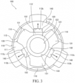
- the bump stopper 100 includes the following: a cap 110 that covers the top end side of the cylinder 10; a stopper 120 that is supported by the cap 110; and a collar 130 that is provided to the inside of the cap 110.
- the cap 110 is provided with a plate-shaped part 111 having a first rod hole 112 into which the piston rod 30 can be inserted, and a cylindrical part 115 which can receive the top end side of the cylinder 10.
- the first rod hole 112 is formed so as to penetrate between a first surface (inner surface) 111a and a second surface (outer surface) 111b of the plate-shaped part 111.
- the first rod hole 112 will also be referred to simply as the "rod hole 112".
- the rod hole 112 is positioned in approximately the center of the plate-shaped part 111.
- the inner peripheral surface of the rod hole 112 includes the following: a plurality of curved surface parts 112a formed in an arc shape; and a plurality of recessed surface parts 112b formed so as to be recessed from the curved surface parts 112a toward the outside of the plate-shaped part 111. Openings 112c which are approximately rectangular shaped are defined by the recessed surface parts 112b.
- each recessed surface part 112b is formed by three flat surfaces, but each recessed surface part 112b may be formed by a single curved surface. If each recessed surface part 112b is formed by a single curved surface, the openings 112c are defined in an approximately semicircular shape.
- each arc-shaped curved surface part 112a is approximately the same, and the curvature radius of each curved surface part 112a is larger than the radius of the piston rod 30. Therefore, in a state in which the bump stopper 100 is attached to the cylinder 10 (refer to FIG. 1 ), a gap is formed between the inner wall surface of the rod hole 112 and the piston rod 30.
- the cylindrical part 115 is formed to be continuous with the plate-shaped part 111.
- the inner surface 111a of the plate-shaped part 111 opposes the end surface (oil seal 14) of the cylinder 10.
- the cylindrical part 115 has a plurality of protrusions 116 that protrude toward the inside.
- the plurality of protrusions 116 are formed by depressing the outer peripheral surface of the cylindrical part 115. In a state in which the cylindrical part 115 has received the cylinder 10, the plurality of protrusions 116 abut the outer peripheral surface of the cylinder 10 so as to push open the cylindrical part 115. Therefore, a relatively large force is necessary to pull out the cylinder 10 from the cap 110, and the cap 110 can be prevented from coming off of the cylinder 10.
- the stopper 120 is provided to the outer surface 111b of the plate-shaped part 111, and is fixed to the cap 110 by projection welding.
- the bump cushion 40 is received and stopped by the stopper 120 during contraction of the shock absorber 1.
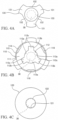
- a circular second rod hole 121 is formed in approximately the center of the stopper 120 (refer to FIG. 4C ).
- the bump stopper 100 is attached to the cylinder 10 in a state in which the piston rod 30 is inserted into the second rod hole 121.
- the inner peripheral surface of the second rod hole 121 of the stopper 120 is positioned more toward the inside than the inner peripheral surface of the rod hole 112 of the plate-shaped part 111. Therefore, the gap between the stopper 120 and the piston rod 30 is smaller than the gap between the plate-shaped part 111 and the piston rod 30. Thus, regardless of the size of the rod hole 112 of the plate-shaped part 111, the bump cushion 40 does not readily enter into the gap between the stopper 120 and the piston rod 30, and breakage of the bump cushion 40 can be prevented.
- the stopper 120 is provided to the outer surface 111b of the plate-shaped part 111, the stopper 120 is separated from the oil seal 14 in the axial direction of the piston rod 30. Therefore, even if the gap between the stopper 120 and the piston rod 30 is narrowed, contact between the stopper 120 and the oil seal 14 (more specifically, the lip 14c) can be prevented.
- the gap between the plate-shaped part 111 and the piston rod 30 is larger than the gap between the stopper 120 and the piston rod 30, the inner peripheral surface of the rod hole 112 of the plate-shaped part 111 is separated from the lip 14c in the radial direction of the piston rod 30. Therefore, even if the interval between the plate-shaped part 111 and the cylinder 10 is narrowed, contact between the plate-shaped part 111 and the lip 14c can be prevented.
- the collar 130 is provided to the inner surface 111a of the plate-shaped part 111, and is fixed to the cap 110 by projection welding. In a state in which the bump stopper 100 is attached to the cylinder 10, the collar 130 opposes the cylinder 10 and separates the plate-shaped part 111 and the cylinder 10. Therefore, the stopper 120 is sufficiently separated from the oil seal 14, and contact between the stopper 120 and the oil seal 14 can be more reliably prevented.
- the collar 130 includes: a plurality of support parts 131 that support the plate-shaped part 111; and a plurality of connection parts 132 that connect adjacent support parts 131.
- the plurality of support parts 131 are integrated by the connections parts 132.
- the collar 130 is formed as a single member. Therefore, when attaching the collar 130 to the cap 110, the collar 130 can be easily handled. The same effect is achieved in the second and third embodiments to be explained below.
- a circular third rod hole 133 is formed in the collar 130 by the plurality of support parts 131 and the plurality of connection parts 132.
- the bump stopper 100 is attached to the cylinder 10 in a state in which the piston rod 30 is inserted into the third rod hole 133 of the collar 130.
- the radius of the third rod hole 133 of the collar 130 matches the curvature radius of the curved surface parts 112a of the plate-shaped part 111, and the inner peripheral surface of the third rod hole 133 and the curved surface parts 112a are continuous without any level differences therebetween. Since the gap between the plate-shaped part 111 and the piston rod 30 is larger than the gap between the stopper 120 and the piston rod 30, the inner peripheral surface of the third rod hole 133, which is continuous with the curved surface parts 112a of the plate-shaped part 111 without any level differences therebetween, is sufficiently separated from the lip 14c in the radial direction of the piston rod 30. Therefore, contact between the collar 130 and the lip 14c is prevented.
- the plurality of support parts 131 are arranged in a radial manner between adjacent openings 112c. Thereby, radial-shaped passages 140 which communicate with the openings 112c of the rod hole 112 are formed between adjacent support parts 131.
- the passages 140 communicate with the outside of the cylindrical part 115 via the gap between the outer peripheral surface of the cylinder 10 and the inner peripheral surface of the cylindrical part 115.
- the "outside of the cylindrical part 115" indicates the spaces excluding the inside of the cylindrical part 115.
- the "outside of the cylindrical part 115" includes the space to the left side of the left end of the cylindrical part 115, the space to the right side of the right end of the cylindrical part 115, the space on the top side of the top end of the cylindrical part 115, and the space on the bottom side of the bottom end of the cylindrical part 115.
- the passages 140 communicate with the space on the bottom side of the bottom end of the cylindrical part 115 via the gap between the outer peripheral surface of the cylinder 10 and the inner peripheral surface of the cylindrical part 115.
- the passages 140 are formed between adjacent support parts 131, the passage forming portions of the plate-shaped part 111 are supported by the support parts 131 on both sides, and thus these passage forming portions do not easily deform. Therefore, deformation of the cross-section shape of the passages 140 can be prevented, and fluid and dust that have flowed into the cap 110 from the rod hole 112 of the plate-shaped part 111 can be more reliably discharged to the outside of the cap 110.
- a flow of air is generated around the bump cushion 40 in accordance with the contraction of the bump cushion 40. Due to this flow of air, air and dust may flow into the gap between the inner peripheral surface of the rod hole 112 of the plate-shaped part 111 and the piston rod 30. Further, liquid, i.e. water, may flow into the gap between the inner peripheral surface of the rod hole 112 of the plate-shaped part 111 and the piston rod 30.
- the passages 140 allow the rod hole 112 of the plate-shaped part 111 to communicate with the outside of the cylindrical part 115 via the inside of the cylindrical part 115. Therefore, fluid and dust that have flowed into the gap between the inner peripheral surface of the rod hole 112 of the plate-shaped part 111 and the piston rod 30 is discharged to the outside of the cap 110 via the openings 112c of the rod hole 112 and the passages 140.
- connection parts 132 straddle over the openings 112c of the rod hole 112 so as to extend more toward the inside in the radial direction than the recessed surface parts 112b. Therefore, the passages 140 communicate with the openings 112c of the rod hole 112. Thus, the flow in the passages 140 is not blocked by the connection parts 132, and fluid and dust that flow into the cap 110 from the rod hole 112 can be more reliably discharged to the outside of the cap 110.
- connection parts 132 are not depressed relative to the support parts 131, and are formed in a planar shape along the support parts 131. Therefore, the collar 130 is simple. In addition, the collar can be produced easily because it is not necessary to consider a gap between the connection parts 132 and the stopper 120 so as to avoid contact between the connection parts 132 and the stopper 120.
- the flow passage cross-section of the passages 140 is larger than the flow passage cross-section in the gap between the stopper 120 and the piston rod 30. Therefore, fluid and dust that have flowed into the passages 140 from this gap do not easily stagnate within the passages 140. Thus, fluid and dust that have flowed into the cap 110 from the rod hole 112 can be more reliably discharged to the outside of the cap 110.
- the passages 140 that allow the rod hole 112 to communicate with the outside of the cap 110 are formed by the cap 110 and the collar 130, it is not necessary to form the cap 110 in a complex shape. Therefore, the bump stopper 100 can be formed easily and reductions in the strength of the bump stopper 100 can be prevented.
- FIG. 5 is a bottom view illustrating a bump stopper 101 according to an alternative embodiment of the present embodiment.
- the circular rod hole 112 is formed in the plate-shaped part 111.
- the collar 130 does not include portions corresponding to the connection parts 132 (refer to FIGS. 3 and 4A ), and the plurality of support parts 131 are separated from each other.
- the passages 140 are formed by the collar 130 and the cap 110. Therefore, the bump stopper 101 can be formed easily and reductions in the strength of the bump stopper 101 can be prevented.
- the width of the passages 140 is expanded. Therefore, flow resistance in the passages 140 can be reduced, and fluid and dust that have flowed into the cap 110 from the rod hole 121 can be more reliably discharged to the outside of the cap 110.
- the operation of the shock absorber 1 will be explained. Since the bump stopper 100 cooperates with the bump cushion 40 to absorb shocks only when the shock absorber 1 contracts, herein, only the contraction operation of the shock absorber 1 will be explained.
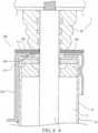
- the bump cushion 40 abuts the bump stopper 100 (refer to FIG. 6 ). Shocks generated during maximum contraction of the shock absorber 1 are absorbed by the contraction of the bump cushion 40.
- a flow of air is generated around the bump cushion 40 in accordance with the contraction of the bump cushion 40. At this time, fluid and dust flow into the gap between the inner peripheral surface of the rod hole 112 of the plate-shaped part 111 and the piston rod 30.
- Fluid and dust that have flowed into the gap between the inner peripheral surface of the rod hole 112 of the plate-shaped part 111 and the piston rod 30 is discharged to the outside of the cap 110 via the passages 140 (the passages indicated by the arrow mark in FIG. 6 ). Therefore, increases in the pressure within the cap 110 and accumulations of dust within the cap 110 can be prevented.
- FIG. 7 is a cross-section view of a shock absorber 2 provided with the bump stopper 200.
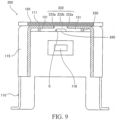
- FIG. 8 is a bottom view of the bump stopper 200.
- FIG. 9 is a cross-section view along line IX-IX shown in FIG. 8 .
- the bump stopper 200 includes the following: the cap 110; the stopper 120; and a collar 230 provided to the inside of the cap 110.
- the collar 230 includes a plurality of support parts 131, and a plurality of connection parts 232 which connect adjacent support parts 131.
- connection parts 232 are depressed in the axial direction of the piston rod 30 relative to the support parts 131 so that the connection parts 232 enter into the rod hole 112.
- each connection part 232 includes base parts 232a formed to be continuous with the support parts 131, and a middle part 232b formed to be continuous with the base parts 232a.
- the base parts 232a are bent toward the stopper 120, and the middle part 232b contacts the stopper 120.
- the thickness of the connection parts 232 is approximately equal to the thickness of the support parts 131, and the depression of the connection parts 232 is formed by bending the base parts 232a. Therefore, the connection parts protrude in the axial direction of the piston rod 30 relative to the support parts 131.
- the depression of the connection parts 232 may be formed without bending the base parts 232a.
- the depression may be formed by making the thickness of the connection parts 232 less than the thickness of the support parts 131.
- the bump stopper 200 also achieves the following effects.
- connection parts 232 are depressed, passages 240 are formed linearly along the end surface of the cylinder 10 (surface of the oil seal 14) between the connection parts 232 and the cylinder 10 as shown in FIG. 7 . Therefore, flow resistance in the passages 240 can be reduced, and fluid and dust that have flowed into the cap 110 from the rod hole 112 can be more reliably discharged to the outside of the cap 110. The same effects are also achieved in the third embodiment to be explained below.
- connection parts 232 do not have to contact the stopper 120. Further, the connection parts 232 may contact the inner wall surface of the rod hole 112.
- shock absorber 2 The operation of the shock absorber 2 is basically the same as that of the shock absorber 1, and thus an explanation thereof will be omitted herein.
- a bump stopper 300 according to a third embodiment of the present invention will be explained. Constituent elements which are the same as those in the first and second embodiments will be assigned the same reference numerals, and explanations thereof will be omitted.
- FIG. 10 is a cross-section view of a shock absorber 3 provided with the bump stopper 300.
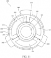
- FIG. 11 is a bottom view of the bump stopper 300.
- the bump stopper 300 includes: a cap 310; the stopper 120; and a collar 330 provided to the inside of the cap 310.
- a circular rod hole 312 is formed in a plate-shaped part 311 of the cap 310. The piston rod 30 can be inserted into the rod hole 312.
- connection part 332 of the collar 330 is positioned more toward the inside in the radial direction than the circular inner peripheral surface of the rod hole 312.
- connection part 332 is formed to be depressed relative to the support parts 131.
- connection parts 232 are depressed so as to fit into the openings 112c as shown in FIG. 9 , a raised part S of the depression is formed in the flow passage cross-section of the passages 240.
- the passages 240 are narrowed by an amount equivalent to the raised part S.
- connection part 332 is positioned more toward the inside in the radial direction than the circular inner peripheral surface of the rod hole 312, there is no raised part of the depression in the flow passage cross-section of the passages 340, and the width of the passages 340 is expanded. Therefore, flow resistance in the passages 340 can be reduced, and fluid and dust that have flowed into the cap 310 from the rod hole 312 can be more reliably discharged to the outside of the cap.
- connection part 332 of the collar 330 is formed in an annular shape and includes a third rod hole 333.
- the piston rod 30 can be inserted into the third rod hole 333.
- the plurality of support parts 131 are disposed on the outer periphery of the annular connection part 332.
- the collar 330 is fixed to the cap 310 by joining the connection part 332 and the inner peripheral surface of the rod hole 312 of the plate-shaped part 311.
- connection part 332 is disposed within the rod hole 312 of the plate-shaped part 311. Therefore, the connection part 332 is not covered by the cap 310. Thus, when the collar 330 is fixed to the cap 310, the connection part 332 can be seen from the outside of the cap 310, and the connection part 332 can be easily joined to the inner peripheral surface of the rod hole 312 of the plate-shaped part 311.
- connection part 332 may or may not contact the stopper 120.
- the bump stopper 300 also achieves the following effects.
- connection part 332 is not covered by the cap 310, when the collar 330 is fixed to the cap 310, the connection part 332 can be seen from the outside of the cap 310, and the connection part 332 can be easily joined to the inner peripheral surface of the rod hole 312 of the plate-shaped part 311.
- shock absorber 3 The operation of the shock absorber 3 is basically the same as that of the shock absorber 1, and thus an explanation thereof will be omitted herein.
- the bump stopper 100, 101, 200, 300 absorbs shocks generated during maximum contraction of the shock absorber 1, 2, 3 in cooperation with the bump cushion 40.
- the bump stopper 100, 101, 200, 300 includes the following: the cap 110, 310 provided with the plate-shaped part 111, 311 having the rod hole 112, 312 into which the piston rod 30 of the shock absorber 1, 2, 3 inserted, and the cylindrical part 115 configured to receive a portion of the cylinder 10 of the shock absorber 1, 2, 3; the stopper 120 provided to the plate-shaped part 111, 311 and configured to receive the bump cushion 40; and the collar 130, 230, 330 provided to the plate-shaped part 111, 311 opposing the cylinder 10.
- the collar 130, 230, 330 is provided to the plate-shaped part 111, 311 opposing the cylinder 10, it is not necessary to form the cap 110, 310 in a complex shape. Therefore, the bump stopper 100, 101, 200, 300 which is easy to manufacture and has sufficient strength can be provided.
- the collar 130, 230, 330 includes the plurality of support parts 131 arranged in a radial manner on the plate-shaped part 111, 311 and configured to support the plate-shaped part 111, 311, and the passages 140, 240, 340 which is configured to allow the rod hole 112, 312 to communicate with the outside of the cap 110, 310 via the inside of the cylindrical part 115, are formed by the cap 110, 310 and the collar 130, 230, 330.
- the passages 140, 240, 340 are formed between adjacent support parts 131.
- the passages 140, 240, 340 are formed between adjacent support parts 131, the passage forming portions of the plate-shaped part 111, 311 are supported by the support parts 131 on both sides, and thus these passage forming portions do not easily deform. Therefore, deformation of the cross-section shape of the passages 140, 240, 340 can be prevented, and fluid and dust that have flowed into the cap 110, 310 from the rod hole 112, 312 can be more reliably discharged to the outside of the cap 110, 310.
- the collar 130, 230, 330 further includes the connection parts 132, 232, 332 that connect adjacent support parts 131.
- connection parts 132, 232, 332 connect adjacent support parts 131, the plurality of support parts 131 are integrated by the connection parts 132, 232, 332.
- the collar 130, 230, 330 can be easily handled.
- the rod hole 112 has the openings 112c, and the connection parts 132 are positioned more toward the inside in the radial direction than the inner peripheral surface of the openings 112c and are formed in a planar shape along the support parts 131.
- connection parts 132 are formed in a planar shape along the support parts 131, the collar 130 is simple.
- the collar 130 can be produced easily because it is not necessary to produce the collar 130 in consideration of a gap between the connection parts 132 and the stopper 120 so as to avoid contact between the connection parts 132 and the stopper 120.
- the rod hole 112 has the openings 112c, and the connection parts 232 are positioned more toward the inside in the radial direction than the inner peripheral surface of the openings 112c and are formed to be depressed relative to the support parts 131.
- connection parts 232 are formed to be depressed relative to the support parts 131, the passages 240 are formed linearly along the end surface of the cylinder 10. Therefore, flow resistance in the passages 240 can be reduced, and fluid and dust that have flowed into the cap 110 from the rod hole 112 can be more reliably discharged to the outside of the cap 110.
- the rod hole 312 is circular, and the connection part 332 is positioned more toward the inside in the radial direction than the circular inner peripheral surface of the rod hole 312 and is formed to be depressed relative to the support parts 131.
- connection part 332 is positioned more toward the inside in the radial direction than the circular inner peripheral surface of the rod hole 312, there is no raised part of the depression in the flow passage cross-section of the passages 340, and the width of the passages 340 is expanded. Therefore, flow resistance in the passages 340 can be reduced, and fluid and dust that have flowed into the cap 310 from the rod hole 312 can be more reliably discharged to the outside of the cap 310.
- connection part 332 is formed in an annular shape and is disposed within the rod hole 312 of the plate-shaped part 311.
- connection part 332 since the annular connection part 332 is disposed within the rod hole 312, the connection part 332 is not covered by the cap 310. Thus, when the collar 330 is fixed to the cap 310, the connection part 332 can be seen from the outside of the cap 310, and the connection part 332 can be easily joined to the inner wall surface of the rod hole 312.
- the plurality of support parts 131 are separated from each other.
- the bump stopper 100, 101, 200, 300 is characterized in that the inner peripheral surface of the stopper 120 is positioned more toward the inside in the radial direction than the inner peripheral surface of the rod hole 112, 312 of the plate-shaped part 111, 311.
- the gap between the stopper 120 and the piston rod 30 is smaller than the gap between the inner peripheral surface of the rod hole 112, 312 and the piston rod 30.
- the bump cushion 40 does not readily enter into the gap between the stopper 120 and the piston rod 30, and breakage of the bump cushion 40 can be prevented.
- the shock absorber 1, 2, 3 is characterized by including the bump stopper 100, 101, 200, 300 described above and the piston rod 30 inserted into the rod hole 112, 312, wherein the flow passage cross-section of the passages 140, 240, 340 is larger than the flow passage cross-section in the gap between the stopper 120 and the piston rod 30.
Landscapes
- Engineering & Computer Science (AREA)
- General Engineering & Computer Science (AREA)
- Mechanical Engineering (AREA)
- Fluid-Damping Devices (AREA)
Claims (11)
- Ein Anschlagstopper (100, 101, 200, 300) zum Absorbieren von Stößen, die während der maximalen Kontraktion eines Stoßdämpfers (1, 2, 3) in Zusammenarbeit mit einem Stoßdämpferkissen (40) erzeugt werden, wobei der Anschlagstopper (100, 101, 200, 300) aufweist:eine Kappe (110, 310), die einen plattenförmigen Teil (111, 311) mit einem Stangenloch (112, 312), in das eine Kolbenstange (30) des Stoßdämpfers (1, 2, 3) eingesetzt werden kann, und einen zylindrischen Teil (115), der so konfiguriert ist, dass er einen Abschnitt eines Zylinders (10) des Stoßdämpfers (1, 2, 3) aufnimmt, umfassteinen Stopper (120), der an dem plattenförmigen Teil (111, 311) vorgesehen ist, wobei der Stopper (120) konfiguriert ist, um das Stoßdämpferkissen (40) aufzunehmen; undeinen Kragen (130, 230, 330), der an dem plattenförmigen Teil (111, 311) vorgesehen ist und so konfiguriert ist, dass er dem Zylinder (10) in einem zusammengebauten Zustand gegenüberliegt, wobeider Kragen (130, 230, 330) eine Vielzahl von Stützteilen (131) umfasst, die in einer radialen Weise auf dem plattenförmigen Teil (111, 311) angeordnet sind, wobei die Vielzahl von Stützteilen (131) konfiguriert ist, um das plattenförmige Teil (111, 311) zu stützenein Durchgang (140, 240, 340) durch die Kappe (110, 310) und den Kragen (130, 230, 330) gebildet wird, wobei der Durchgang (140, 240, 340) so konfiguriert ist, dass das Stangenloch (112, 312) mit einer Außenseite des zylindrischen Teils (115) über eine Innenseite des zylindrischen Teils (115) in Verbindung steht, undder Durchgang (140, 240, 340) zwischen den benachbarten Stützteilen (131) ausgebildet ist.
- Der Anschlagstopper (100, 200, 300) nach Anspruch 1, wobei der Kragen (130, 230, 330) ferner ein Verbindungsteil (132, 232, 332) umfasst, das so konfiguriert ist, dass es die benachbarten Stützteile (131) verbindet.
- Der Anschlagstopper (100) nach Anspruch 2, wobeidas Stangenloch (112) eine Öffnung (112c) aufweist, unddas Verbindungsteil (132) in radialer Richtung weiter innen angeordnet ist als eine innere Umfangsfläche der Öffnung (112c), wobei das Verbindungsteil (132) in einer ebenen Form entlang der Stützteile (131) ausgebildet ist.
- Der Anschlagstopper (200) nach Anspruch 2, wobeidas Stangenloch (112) eine Öffnung (112c) aufweist, unddas Verbindungsteil (232) in radialer Richtung weiter innen angeordnet ist als eine innere Umfangsfläche der Öffnung (112c), wobei das Verbindungsteil (232) so ausgebildet ist, dass es relativ zu den Stützteilen (131) niedergedrückt wird.
- Der Anschlagstopper (300) nach Anspruch 2, wobeidas Stangenloch (312) kreisförmig ist, unddas Verbindungsteil (332) in einer radialen Richtung weiter innen angeordnet ist als eine kreisförmige innere Umfangsfläche des Stangenlochs (312), wobei das Verbindungsteil (332) so ausgebildet ist, dass es relativ zu den Stützteilen (131) eingedrückt wird.
- Der Anschlagstopper (300) nach Anspruch 5, wobei das Verbindungsteil (332) ringförmig ausgebildet ist und innerhalb des Stangenlochs (312) des plattenförmigen Teils (311) angeordnet ist.
- Der Anschlagstopper (101) nach Anspruch 1, wobei die mehreren Stützteile (131) voneinander getrennt sind.
- Der Anschlagstopper (100, 101, 200, 300) nach Anspruch 1, wobei eine innere Umfangsfläche des Anschlags (120) in radialer Richtung weiter innen angeordnet ist als die innere Umfangsfläche des Stangenlochs (112, 312) des plattenförmigen Teils (111, 311).
- Der Anschlagstopper (100, 101, 200, 300) nach einem der Ansprüche 1 bis 8, wobeider Stopper (120) an einer Außenfläche (111b) des plattenförmigen Teils (111, 311) vorgesehen ist,der Kragen (130, 230, 330) an einer Innenfläche (111a, 311a) des plattenförmigen Teils (111, 311) vorgesehen ist, undder Stopfen (120) und der Kragen (130, 230, 330) durch Buckelschweißen an der Kappe (110, 310) befestigt sind.
- Ein Stoßdämpfer (1, 2, 3) mit:dem Anschlagstopper (100, 101, 200, 300) nach Anspruch 1; undeine Kolbenstange (30), die in das Stangenloch (112, 312) des plattenförmigen Teils (111, 311) eingesetzt ist,wobei ein Strömungsdurchgangsquerschnitt des Durchgangs (140, 240, 340) größer ist als ein Strömungsdurchgangsquerschnitt in einem Spalt zwischen dem Stopper (120) und der Kolbenstange (30).
- Ein Stoßdämpfer (1, 2, 3), aufweisend:den Anschlagstopper (100, 101, 200, 300) nach einem der Ansprüche 1 bis 9;einen Zylinder (10) mit einem Abschnitt, der in dem zylindrischen Teil (115) aufgenommen ist; undeine Kolbenstange (30), die in den Zylinder (10) eingesetzt ist, so dass sie sich in den Zylinder (10) hinein und aus ihm heraus bewegen kann,wobei der Zylinder (10) umfasst:ein Rohr (12);eine Stangenführung (13), die an einem Ende des Rohrs (12) vorgesehen ist, und eine Buchse (15), die am Innenumfang der Stangenführung (13) vorgesehen ist, wobei die Stangenführung so konfiguriert ist, dass sie die Kolbenstange (30) über die Buchse (15) gleitend stützt; undeine Öldichtung (14), die an einem inneren Umfang des Rohrs (12) vorgesehen ist, wobei die Öldichtung (14) eine ringförmige Basis (14a) und Lippen (14b, 14c) aufweist, die an dem inneren Umfang der Basis (14a) vorgesehen sind, und wobei die Lippen (14b, 14c) so konfiguriert sind, dass sie einen äußeren Umfang der Kolbenstange (30) gleitend berühren, um zu verhindern, dass Arbeitsfluid innerhalb des Zylinders (10) nach außen leckt und dass fremde Verunreinigungen in den Zylinder (10) fließen,wobei die Stangenführung (13) und die Öldichtung (14) an dem Rohr (12) befestigt sind, indem ein Ende des Rohrs (12) so gebogen wird, dass es der Öldichtung (14) in axialer Richtung gegenüberliegt, undwobei der Kragen (130, 230, 330) zwischen dem plattenförmigen Teil (111, 311) und dem Ende in dem Rohr (12) vorgesehen ist, das so gebogen ist, dass es der Öldichtung (14) in der axialen Richtung gegenüberliegt, wobei der Kragen (130, 230, 330) so konfiguriert ist, dass er die Öldichtung (14) und den plattenförmigen Teil (111, 311) trennt.
Applications Claiming Priority (2)
| Application Number | Priority Date | Filing Date | Title |
|---|---|---|---|
| JP2015227816A JP6616672B2 (ja) | 2015-11-20 | 2015-11-20 | バンプストッパ、及び緩衝器 |
| PCT/JP2016/077582 WO2017086012A1 (ja) | 2015-11-20 | 2016-09-16 | バンプストッパ、及び緩衝器 |
Publications (3)
| Publication Number | Publication Date |
|---|---|
| EP3379102A1 EP3379102A1 (de) | 2018-09-26 |
| EP3379102A4 EP3379102A4 (de) | 2019-07-10 |
| EP3379102B1 true EP3379102B1 (de) | 2025-06-11 |
Family
ID=58718656
Family Applications (1)
| Application Number | Title | Priority Date | Filing Date |
|---|---|---|---|
| EP16866015.7A Active EP3379102B1 (de) | 2015-11-20 | 2016-09-16 | Anschlagstopper und puffer |
Country Status (6)
| Country | Link |
|---|---|
| US (1) | US10794447B2 (de) |
| EP (1) | EP3379102B1 (de) |
| JP (1) | JP6616672B2 (de) |
| KR (1) | KR102542393B1 (de) |
| CN (2) | CN110836237A (de) |
| WO (1) | WO2017086012A1 (de) |
Families Citing this family (2)
| Publication number | Priority date | Publication date | Assignee | Title |
|---|---|---|---|---|
| US11566679B2 (en) * | 2020-11-03 | 2023-01-31 | DRiV Automotive Inc. | Bumper cap for damper |
| DE112022001230T5 (de) * | 2021-02-24 | 2023-12-07 | Hitachi Astemo, Ltd. | Stossfängerkappe und Stossdämpfer |
Family Cites Families (31)
| Publication number | Priority date | Publication date | Assignee | Title |
|---|---|---|---|---|
| US3346272A (en) * | 1965-10-14 | 1967-10-10 | Monroe Auto Equipment Co | Vehicle suspension device |
| DE7834927U1 (de) * | 1978-11-24 | 1979-03-29 | Fichtel & Sachs Ag, 8720 Schweinfurt | Stoßdämpfer oder Federbein mit einer Gummihohlfeder |
| DE2922437A1 (de) * | 1979-06-01 | 1980-12-11 | Fichtel & Sachs Ag | Zweirohrschwingungsdaempfer mit universell anwendbarer kolbenstangenfuehrung |
| US4397452A (en) * | 1980-11-28 | 1983-08-09 | Ford Motor Company | Hydro-mechanical stop for a shock absorber |
| JPS5820739U (ja) * | 1981-07-31 | 1983-02-08 | 厚木自動車部品株式会社 | シヨツクアブソ−バのバンパ−ラバ−ストツパキヤツプ |
| JPS6071746U (ja) * | 1983-10-24 | 1985-05-21 | カヤバ工業株式会社 | 油圧緩衝器のバンプストツパ |
| US4828232A (en) * | 1983-11-14 | 1989-05-09 | General Motors Corporation | Vehicle air suspension strut with compliant cover plate assembly |
| US4724938A (en) * | 1985-12-09 | 1988-02-16 | General Motors Corporation | Method of making and checking the jounce and rebound actions of an hydraulic damper |
| US4795010A (en) * | 1986-04-10 | 1989-01-03 | Tokico Ltd. | Hydraulic damper |
| JPH0523862Y2 (de) * | 1986-04-11 | 1993-06-17 | ||
| US5078370A (en) * | 1990-11-23 | 1992-01-07 | Chrysler Corporation | Upper mount for suspension strut |
| US5667041A (en) * | 1995-11-03 | 1997-09-16 | General Motors Corporation | Suspension strut with hydraulic stop |
| DE19608771A1 (de) * | 1996-03-07 | 1997-04-24 | Fichtel & Sachs Ag | Führung für ein Kolben-Zylinderaggregat |
| JPH09317811A (ja) * | 1996-05-27 | 1997-12-12 | Kayaba Ind Co Ltd | 油圧緩衝器におけるバンプストッパ係止構造 |
| DE19644239C2 (de) * | 1996-10-24 | 1999-08-19 | Mannesmann Sachs Ag | Endkappe für einen Schwingungsdämpfer |
| JP4230568B2 (ja) * | 1998-07-24 | 2009-02-25 | 株式会社ショーワ | 油圧緩衝器のばねシート固定構造 |
| US6186486B1 (en) * | 1999-07-30 | 2001-02-13 | Delphi Technologies, Inc. | Jounce bumper plate |
| JP4048083B2 (ja) * | 2002-06-28 | 2008-02-13 | カヤバ工業株式会社 | バンプストッパ |
| DE10325730B4 (de) * | 2003-06-06 | 2006-02-02 | Zf Sachs Ag | Schwingungsdämpfer für Fahrzeuge |
| JP2006144952A (ja) * | 2004-11-22 | 2006-06-08 | Kayaba Ind Co Ltd | 緩衝器 |
| JP2006220162A (ja) * | 2005-02-08 | 2006-08-24 | Kayaba Ind Co Ltd | 緩衝器 |
| JP5000235B2 (ja) * | 2006-08-25 | 2012-08-15 | 日産自動車株式会社 | シリンダ装置 |
| JP5206965B2 (ja) * | 2008-01-31 | 2013-06-12 | 日立オートモティブシステムズ株式会社 | 流体圧緩衝器 |
| US8991572B2 (en) * | 2009-09-03 | 2015-03-31 | GM Global Technology Operations LLC | Leak-proof damper having self-diagnostic feature |
| JP5783771B2 (ja) * | 2011-03-31 | 2015-09-24 | 日立オートモティブシステムズ株式会社 | 緩衝器 |
| US9302561B2 (en) * | 2011-10-28 | 2016-04-05 | Honda Motor Co., Ltd. | Mount structure for vehicle damper and mount installation method for vehicle damper |
| CN202468822U (zh) * | 2012-02-16 | 2012-10-03 | 浙江万向系统有限公司 | 一种多点固定整体式减振器的防尘盖 |
| CN202888055U (zh) * | 2012-09-17 | 2013-04-17 | 常熟市通用电器厂有限公司 | 复合缓冲器 |
| KR101371760B1 (ko) * | 2012-12-21 | 2014-03-07 | 현대자동차(주) | 쇼크업소버장치 |
| JP5799069B2 (ja) * | 2013-10-08 | 2015-10-21 | カヤバ工業株式会社 | 緩衝器 |
| JP6435741B2 (ja) * | 2014-09-22 | 2018-12-12 | トヨタ自動車株式会社 | バンプストッパキャップ |
-
2015
- 2015-11-20 JP JP2015227816A patent/JP6616672B2/ja active Active
-
2016
- 2016-09-16 CN CN201911120749.9A patent/CN110836237A/zh active Pending
- 2016-09-16 WO PCT/JP2016/077582 patent/WO2017086012A1/ja not_active Ceased
- 2016-09-16 KR KR1020187015125A patent/KR102542393B1/ko active Active
- 2016-09-16 US US15/773,249 patent/US10794447B2/en active Active
- 2016-09-16 CN CN201680064497.0A patent/CN108350974B/zh active Active
- 2016-09-16 EP EP16866015.7A patent/EP3379102B1/de active Active
Also Published As
| Publication number | Publication date |
|---|---|
| KR20180084827A (ko) | 2018-07-25 |
| EP3379102A1 (de) | 2018-09-26 |
| CN110836237A (zh) | 2020-02-25 |
| US10794447B2 (en) | 2020-10-06 |
| KR102542393B1 (ko) | 2023-06-09 |
| US20180320752A1 (en) | 2018-11-08 |
| JP6616672B2 (ja) | 2019-12-04 |
| JP2017096369A (ja) | 2017-06-01 |
| CN108350974A (zh) | 2018-07-31 |
| EP3379102A4 (de) | 2019-07-10 |
| WO2017086012A1 (ja) | 2017-05-26 |
| CN108350974B (zh) | 2020-12-04 |
Similar Documents
| Publication | Publication Date | Title |
|---|---|---|
| JP6351746B2 (ja) | 緩衝器 | |
| JP6335019B2 (ja) | 緩衝器 | |
| JP6374701B2 (ja) | 緩衝器 | |
| US8109491B2 (en) | Vibration damper with a stop spring | |
| CN106460995A (zh) | 缓冲器 | |
| EP3379102B1 (de) | Anschlagstopper und puffer | |
| EP3214337B1 (de) | Stossdämpfer | |
| JP6379219B2 (ja) | シリンダ装置 | |
| JP6810603B2 (ja) | シリンダ装置 | |
| JP6838238B2 (ja) | 緩衝器 | |
| CN112119239B (zh) | 具有可调阻尼阀的振动阻尼器 | |
| CN116848338A (zh) | 托架固定部件、缓冲器以及缓冲器的制造方法 | |
| US7559272B2 (en) | Cylinder apparatus | |
| JP7805197B2 (ja) | シリンダ装置 | |
| KR20250140615A (ko) | 완충 장치, 현가 장치 | |
| JP2006070991A (ja) | 緩衝器のバルブ構造 | |
| JP2025025246A (ja) | 緩衝器 | |
| JP2023120536A (ja) | シリンダ装置 | |
| JP2007132484A (ja) | オイルシール | |
| JP2024154296A (ja) | キャップ、緩衝装置 | |
| JP2024154066A (ja) | 緩衝器 | |
| WO2024154337A1 (ja) | 緩衝装置、懸架装置 | |
| JP2017187075A (ja) | ショックアブソーバ及びその製造方法 | |
| JP2008128273A (ja) | ストラットマウント及びその組付構造体 |
Legal Events
| Date | Code | Title | Description |
|---|---|---|---|
| STAA | Information on the status of an ep patent application or granted ep patent |
Free format text: STATUS: THE INTERNATIONAL PUBLICATION HAS BEEN MADE |
|
| PUAI | Public reference made under article 153(3) epc to a published international application that has entered the european phase |
Free format text: ORIGINAL CODE: 0009012 |
|
| STAA | Information on the status of an ep patent application or granted ep patent |
Free format text: STATUS: REQUEST FOR EXAMINATION WAS MADE |
|
| 17P | Request for examination filed |
Effective date: 20180620 |
|
| AK | Designated contracting states |
Kind code of ref document: A1 Designated state(s): AL AT BE BG CH CY CZ DE DK EE ES FI FR GB GR HR HU IE IS IT LI LT LU LV MC MK MT NL NO PL PT RO RS SE SI SK SM TR |
|
| AX | Request for extension of the european patent |
Extension state: BA ME |
|
| DAV | Request for validation of the european patent (deleted) | ||
| DAX | Request for extension of the european patent (deleted) | ||
| A4 | Supplementary search report drawn up and despatched |
Effective date: 20190606 |
|
| RIC1 | Information provided on ipc code assigned before grant |
Ipc: F16F 9/58 20060101AFI20190531BHEP Ipc: F16F 9/36 20060101ALI20190531BHEP Ipc: F16F 9/32 20060101ALI20190531BHEP |
|
| STAA | Information on the status of an ep patent application or granted ep patent |
Free format text: STATUS: EXAMINATION IS IN PROGRESS |
|
| 17Q | First examination report despatched |
Effective date: 20220511 |
|
| GRAP | Despatch of communication of intention to grant a patent |
Free format text: ORIGINAL CODE: EPIDOSNIGR1 |
|
| STAA | Information on the status of an ep patent application or granted ep patent |
Free format text: STATUS: GRANT OF PATENT IS INTENDED |
|
| INTG | Intention to grant announced |
Effective date: 20250116 |
|
| GRAS | Grant fee paid |
Free format text: ORIGINAL CODE: EPIDOSNIGR3 |
|
| GRAA | (expected) grant |
Free format text: ORIGINAL CODE: 0009210 |
|
| STAA | Information on the status of an ep patent application or granted ep patent |
Free format text: STATUS: THE PATENT HAS BEEN GRANTED |
|
| AK | Designated contracting states |
Kind code of ref document: B1 Designated state(s): AL AT BE BG CH CY CZ DE DK EE ES FI FR GB GR HR HU IE IS IT LI LT LU LV MC MK MT NL NO PL PT RO RS SE SI SK SM TR |
|
| REG | Reference to a national code |
Ref country code: GB Ref legal event code: FG4D |
|
| REG | Reference to a national code |
Ref country code: CH Ref legal event code: EP |
|
| REG | Reference to a national code |
Ref country code: IE Ref legal event code: FG4D |
|
| REG | Reference to a national code |
Ref country code: DE Ref legal event code: R096 Ref document number: 602016092552 Country of ref document: DE |
|
| PG25 | Lapsed in a contracting state [announced via postgrant information from national office to epo] |
Ref country code: ES Free format text: LAPSE BECAUSE OF FAILURE TO SUBMIT A TRANSLATION OF THE DESCRIPTION OR TO PAY THE FEE WITHIN THE PRESCRIBED TIME-LIMIT Effective date: 20250611 Ref country code: FI Free format text: LAPSE BECAUSE OF FAILURE TO SUBMIT A TRANSLATION OF THE DESCRIPTION OR TO PAY THE FEE WITHIN THE PRESCRIBED TIME-LIMIT Effective date: 20250611 |
|
| PGFP | Annual fee paid to national office [announced via postgrant information from national office to epo] |
Ref country code: DE Payment date: 20250923 Year of fee payment: 10 |
|
| REG | Reference to a national code |
Ref country code: LT Ref legal event code: MG9D |
|
| PG25 | Lapsed in a contracting state [announced via postgrant information from national office to epo] |
Ref country code: GR Free format text: LAPSE BECAUSE OF FAILURE TO SUBMIT A TRANSLATION OF THE DESCRIPTION OR TO PAY THE FEE WITHIN THE PRESCRIBED TIME-LIMIT Effective date: 20250912 Ref country code: NO Free format text: LAPSE BECAUSE OF FAILURE TO SUBMIT A TRANSLATION OF THE DESCRIPTION OR TO PAY THE FEE WITHIN THE PRESCRIBED TIME-LIMIT Effective date: 20250911 |
|
| REG | Reference to a national code |
Ref country code: NL Ref legal event code: MP Effective date: 20250611 |
|
| PG25 | Lapsed in a contracting state [announced via postgrant information from national office to epo] |
Ref country code: BG Free format text: LAPSE BECAUSE OF FAILURE TO SUBMIT A TRANSLATION OF THE DESCRIPTION OR TO PAY THE FEE WITHIN THE PRESCRIBED TIME-LIMIT Effective date: 20250611 |
|
| PG25 | Lapsed in a contracting state [announced via postgrant information from national office to epo] |
Ref country code: HR Free format text: LAPSE BECAUSE OF FAILURE TO SUBMIT A TRANSLATION OF THE DESCRIPTION OR TO PAY THE FEE WITHIN THE PRESCRIBED TIME-LIMIT Effective date: 20250611 |
|
| PG25 | Lapsed in a contracting state [announced via postgrant information from national office to epo] |
Ref country code: RS Free format text: LAPSE BECAUSE OF FAILURE TO SUBMIT A TRANSLATION OF THE DESCRIPTION OR TO PAY THE FEE WITHIN THE PRESCRIBED TIME-LIMIT Effective date: 20250911 |
|
| PG25 | Lapsed in a contracting state [announced via postgrant information from national office to epo] |
Ref country code: LV Free format text: LAPSE BECAUSE OF FAILURE TO SUBMIT A TRANSLATION OF THE DESCRIPTION OR TO PAY THE FEE WITHIN THE PRESCRIBED TIME-LIMIT Effective date: 20250611 |
|
| PG25 | Lapsed in a contracting state [announced via postgrant information from national office to epo] |
Ref country code: NL Free format text: LAPSE BECAUSE OF FAILURE TO SUBMIT A TRANSLATION OF THE DESCRIPTION OR TO PAY THE FEE WITHIN THE PRESCRIBED TIME-LIMIT Effective date: 20250611 |
|
| PG25 | Lapsed in a contracting state [announced via postgrant information from national office to epo] |
Ref country code: PT Free format text: LAPSE BECAUSE OF FAILURE TO SUBMIT A TRANSLATION OF THE DESCRIPTION OR TO PAY THE FEE WITHIN THE PRESCRIBED TIME-LIMIT Effective date: 20251013 |
|
| REG | Reference to a national code |
Ref country code: AT Ref legal event code: MK05 Ref document number: 1802483 Country of ref document: AT Kind code of ref document: T Effective date: 20250611 |
|
| PG25 | Lapsed in a contracting state [announced via postgrant information from national office to epo] |
Ref country code: IS Free format text: LAPSE BECAUSE OF FAILURE TO SUBMIT A TRANSLATION OF THE DESCRIPTION OR TO PAY THE FEE WITHIN THE PRESCRIBED TIME-LIMIT Effective date: 20251011 |
|
| PG25 | Lapsed in a contracting state [announced via postgrant information from national office to epo] |
Ref country code: AT Free format text: LAPSE BECAUSE OF FAILURE TO SUBMIT A TRANSLATION OF THE DESCRIPTION OR TO PAY THE FEE WITHIN THE PRESCRIBED TIME-LIMIT Effective date: 20250611 Ref country code: SM Free format text: LAPSE BECAUSE OF FAILURE TO SUBMIT A TRANSLATION OF THE DESCRIPTION OR TO PAY THE FEE WITHIN THE PRESCRIBED TIME-LIMIT Effective date: 20250611 |
|
| PG25 | Lapsed in a contracting state [announced via postgrant information from national office to epo] |
Ref country code: CZ Free format text: LAPSE BECAUSE OF FAILURE TO SUBMIT A TRANSLATION OF THE DESCRIPTION OR TO PAY THE FEE WITHIN THE PRESCRIBED TIME-LIMIT Effective date: 20250611 |
|
| PG25 | Lapsed in a contracting state [announced via postgrant information from national office to epo] |
Ref country code: PL Free format text: LAPSE BECAUSE OF FAILURE TO SUBMIT A TRANSLATION OF THE DESCRIPTION OR TO PAY THE FEE WITHIN THE PRESCRIBED TIME-LIMIT Effective date: 20250611 |
|
| PG25 | Lapsed in a contracting state [announced via postgrant information from national office to epo] |
Ref country code: EE Free format text: LAPSE BECAUSE OF FAILURE TO SUBMIT A TRANSLATION OF THE DESCRIPTION OR TO PAY THE FEE WITHIN THE PRESCRIBED TIME-LIMIT Effective date: 20250611 |
|
| PG25 | Lapsed in a contracting state [announced via postgrant information from national office to epo] |
Ref country code: SK Free format text: LAPSE BECAUSE OF FAILURE TO SUBMIT A TRANSLATION OF THE DESCRIPTION OR TO PAY THE FEE WITHIN THE PRESCRIBED TIME-LIMIT Effective date: 20250611 Ref country code: RO Free format text: LAPSE BECAUSE OF FAILURE TO SUBMIT A TRANSLATION OF THE DESCRIPTION OR TO PAY THE FEE WITHIN THE PRESCRIBED TIME-LIMIT Effective date: 20250611 |