EP3374579B1 - Mechanische verbindung für paneele - Google Patents
Mechanische verbindung für paneele Download PDFInfo
- Publication number
- EP3374579B1 EP3374579B1 EP16828703.5A EP16828703A EP3374579B1 EP 3374579 B1 EP3374579 B1 EP 3374579B1 EP 16828703 A EP16828703 A EP 16828703A EP 3374579 B1 EP3374579 B1 EP 3374579B1
- Authority
- EP
- European Patent Office
- Prior art keywords
- locking
- panel
- panels
- edge
- locking element
- Prior art date
- Legal status (The legal status is an assumption and is not a legal conclusion. Google has not performed a legal analysis and makes no representation as to the accuracy of the status listed.)
- Active
Links
Images


Classifications
-
- F—MECHANICAL ENGINEERING; LIGHTING; HEATING; WEAPONS; BLASTING
- F16—ENGINEERING ELEMENTS AND UNITS; GENERAL MEASURES FOR PRODUCING AND MAINTAINING EFFECTIVE FUNCTIONING OF MACHINES OR INSTALLATIONS; THERMAL INSULATION IN GENERAL
- F16B—DEVICES FOR FASTENING OR SECURING CONSTRUCTIONAL ELEMENTS OR MACHINE PARTS TOGETHER, e.g. NAILS, BOLTS, CIRCLIPS, CLAMPS, CLIPS OR WEDGES; JOINTS OR JOINTING
- F16B5/00—Joining sheets or plates, e.g. panels, to one another or to strips or bars parallel to them
- F16B5/0004—Joining sheets, plates or panels in abutting relationship
- F16B5/0032—Joining sheets, plates or panels in abutting relationship by moving the sheets, plates, or panels or the interlocking key parallel to the abutting edge
-
- B—PERFORMING OPERATIONS; TRANSPORTING
- B29—WORKING OF PLASTICS; WORKING OF SUBSTANCES IN A PLASTIC STATE IN GENERAL
- B29C—SHAPING OR JOINING OF PLASTICS; SHAPING OF MATERIAL IN A PLASTIC STATE, NOT OTHERWISE PROVIDED FOR; AFTER-TREATMENT OF THE SHAPED PRODUCTS, e.g. REPAIRING
- B29C65/00—Joining or sealing of preformed parts, e.g. welding of plastics materials; Apparatus therefor
- B29C65/02—Joining or sealing of preformed parts, e.g. welding of plastics materials; Apparatus therefor by heating, with or without pressure
- B29C65/18—Joining or sealing of preformed parts, e.g. welding of plastics materials; Apparatus therefor by heating, with or without pressure using heated tools
-
- B—PERFORMING OPERATIONS; TRANSPORTING
- B29—WORKING OF PLASTICS; WORKING OF SUBSTANCES IN A PLASTIC STATE IN GENERAL
- B29C—SHAPING OR JOINING OF PLASTICS; SHAPING OF MATERIAL IN A PLASTIC STATE, NOT OTHERWISE PROVIDED FOR; AFTER-TREATMENT OF THE SHAPED PRODUCTS, e.g. REPAIRING
- B29C65/00—Joining or sealing of preformed parts, e.g. welding of plastics materials; Apparatus therefor
- B29C65/76—Making non-permanent or releasable joints
-
- B—PERFORMING OPERATIONS; TRANSPORTING
- B29—WORKING OF PLASTICS; WORKING OF SUBSTANCES IN A PLASTIC STATE IN GENERAL
- B29C—SHAPING OR JOINING OF PLASTICS; SHAPING OF MATERIAL IN A PLASTIC STATE, NOT OTHERWISE PROVIDED FOR; AFTER-TREATMENT OF THE SHAPED PRODUCTS, e.g. REPAIRING
- B29C66/00—General aspects of processes or apparatus for joining preformed parts
- B29C66/01—General aspects dealing with the joint area or with the area to be joined
- B29C66/05—Particular design of joint configurations
- B29C66/10—Particular design of joint configurations particular design of the joint cross-sections
- B29C66/11—Joint cross-sections comprising a single joint-segment, i.e. one of the parts to be joined comprising a single joint-segment in the joint cross-section
- B29C66/112—Single lapped joints
-
- B—PERFORMING OPERATIONS; TRANSPORTING
- B29—WORKING OF PLASTICS; WORKING OF SUBSTANCES IN A PLASTIC STATE IN GENERAL
- B29C—SHAPING OR JOINING OF PLASTICS; SHAPING OF MATERIAL IN A PLASTIC STATE, NOT OTHERWISE PROVIDED FOR; AFTER-TREATMENT OF THE SHAPED PRODUCTS, e.g. REPAIRING
- B29C66/00—General aspects of processes or apparatus for joining preformed parts
- B29C66/01—General aspects dealing with the joint area or with the area to be joined
- B29C66/05—Particular design of joint configurations
- B29C66/10—Particular design of joint configurations particular design of the joint cross-sections
- B29C66/13—Single flanged joints; Fin-type joints; Single hem joints; Edge joints; Interpenetrating fingered joints; Other specific particular designs of joint cross-sections not provided for in groups B29C66/11 - B29C66/12
- B29C66/131—Single flanged joints, i.e. one of the parts to be joined being rigid and flanged in the joint area
-
- B—PERFORMING OPERATIONS; TRANSPORTING
- B29—WORKING OF PLASTICS; WORKING OF SUBSTANCES IN A PLASTIC STATE IN GENERAL
- B29C—SHAPING OR JOINING OF PLASTICS; SHAPING OF MATERIAL IN A PLASTIC STATE, NOT OTHERWISE PROVIDED FOR; AFTER-TREATMENT OF THE SHAPED PRODUCTS, e.g. REPAIRING
- B29C66/00—General aspects of processes or apparatus for joining preformed parts
- B29C66/01—General aspects dealing with the joint area or with the area to be joined
- B29C66/05—Particular design of joint configurations
- B29C66/20—Particular design of joint configurations particular design of the joint lines, e.g. of the weld lines
- B29C66/24—Particular design of joint configurations particular design of the joint lines, e.g. of the weld lines said joint lines being closed or non-straight
- B29C66/242—Particular design of joint configurations particular design of the joint lines, e.g. of the weld lines said joint lines being closed or non-straight said joint lines being closed, i.e. forming closed contours
- B29C66/2424—Particular design of joint configurations particular design of the joint lines, e.g. of the weld lines said joint lines being closed or non-straight said joint lines being closed, i.e. forming closed contours being a closed polygonal chain
- B29C66/24243—Particular design of joint configurations particular design of the joint lines, e.g. of the weld lines said joint lines being closed or non-straight said joint lines being closed, i.e. forming closed contours being a closed polygonal chain forming a quadrilateral
- B29C66/24244—Particular design of joint configurations particular design of the joint lines, e.g. of the weld lines said joint lines being closed or non-straight said joint lines being closed, i.e. forming closed contours being a closed polygonal chain forming a quadrilateral forming a rectangle
-
- B—PERFORMING OPERATIONS; TRANSPORTING
- B29—WORKING OF PLASTICS; WORKING OF SUBSTANCES IN A PLASTIC STATE IN GENERAL
- B29C—SHAPING OR JOINING OF PLASTICS; SHAPING OF MATERIAL IN A PLASTIC STATE, NOT OTHERWISE PROVIDED FOR; AFTER-TREATMENT OF THE SHAPED PRODUCTS, e.g. REPAIRING
- B29C66/00—General aspects of processes or apparatus for joining preformed parts
- B29C66/01—General aspects dealing with the joint area or with the area to be joined
- B29C66/05—Particular design of joint configurations
- B29C66/301—Three-dimensional joints, i.e. the joined area being substantially non-flat
-
- B—PERFORMING OPERATIONS; TRANSPORTING
- B29—WORKING OF PLASTICS; WORKING OF SUBSTANCES IN A PLASTIC STATE IN GENERAL
- B29C—SHAPING OR JOINING OF PLASTICS; SHAPING OF MATERIAL IN A PLASTIC STATE, NOT OTHERWISE PROVIDED FOR; AFTER-TREATMENT OF THE SHAPED PRODUCTS, e.g. REPAIRING
- B29C66/00—General aspects of processes or apparatus for joining preformed parts
- B29C66/01—General aspects dealing with the joint area or with the area to be joined
- B29C66/345—Progressively making the joint, e.g. starting from the middle
- B29C66/3452—Making complete joints by combining partial joints
-
- B—PERFORMING OPERATIONS; TRANSPORTING
- B29—WORKING OF PLASTICS; WORKING OF SUBSTANCES IN A PLASTIC STATE IN GENERAL
- B29C—SHAPING OR JOINING OF PLASTICS; SHAPING OF MATERIAL IN A PLASTIC STATE, NOT OTHERWISE PROVIDED FOR; AFTER-TREATMENT OF THE SHAPED PRODUCTS, e.g. REPAIRING
- B29C66/00—General aspects of processes or apparatus for joining preformed parts
- B29C66/50—General aspects of joining tubular articles; General aspects of joining long products, i.e. bars or profiled elements; General aspects of joining single elements to tubular articles, hollow articles or bars; General aspects of joining several hollow-preforms to form hollow or tubular articles
- B29C66/51—Joining tubular articles, profiled elements or bars; Joining single elements to tubular articles, hollow articles or bars; Joining several hollow-preforms to form hollow or tubular articles
- B29C66/53—Joining single elements to tubular articles, hollow articles or bars
- B29C66/534—Joining single elements to open ends of tubular or hollow articles or to the ends of bars
- B29C66/5346—Joining single elements to open ends of tubular or hollow articles or to the ends of bars said single elements being substantially flat
- B29C66/53461—Joining single elements to open ends of tubular or hollow articles or to the ends of bars said single elements being substantially flat joining substantially flat covers and/or substantially flat bottoms to open ends of container bodies
-
- B—PERFORMING OPERATIONS; TRANSPORTING
- B29—WORKING OF PLASTICS; WORKING OF SUBSTANCES IN A PLASTIC STATE IN GENERAL
- B29C—SHAPING OR JOINING OF PLASTICS; SHAPING OF MATERIAL IN A PLASTIC STATE, NOT OTHERWISE PROVIDED FOR; AFTER-TREATMENT OF THE SHAPED PRODUCTS, e.g. REPAIRING
- B29C66/00—General aspects of processes or apparatus for joining preformed parts
- B29C66/80—General aspects of machine operations or constructions and parts thereof
- B29C66/81—General aspects of the pressing elements, i.e. the elements applying pressure on the parts to be joined in the area to be joined, e.g. the welding jaws or clamps
- B29C66/814—General aspects of the pressing elements, i.e. the elements applying pressure on the parts to be joined in the area to be joined, e.g. the welding jaws or clamps characterised by the design of the pressing elements, e.g. of the welding jaws or clamps
- B29C66/8145—General aspects of the pressing elements, i.e. the elements applying pressure on the parts to be joined in the area to be joined, e.g. the welding jaws or clamps characterised by the design of the pressing elements, e.g. of the welding jaws or clamps characterised by the constructional aspects of the pressing elements, e.g. of the welding jaws or clamps
- B29C66/81463—General aspects of the pressing elements, i.e. the elements applying pressure on the parts to be joined in the area to be joined, e.g. the welding jaws or clamps characterised by the design of the pressing elements, e.g. of the welding jaws or clamps characterised by the constructional aspects of the pressing elements, e.g. of the welding jaws or clamps comprising a plurality of single pressing elements, e.g. a plurality of sonotrodes, or comprising a plurality of single counter-pressing elements, e.g. a plurality of anvils, said plurality of said single elements being suitable for making a single joint
-
- B—PERFORMING OPERATIONS; TRANSPORTING
- B29—WORKING OF PLASTICS; WORKING OF SUBSTANCES IN A PLASTIC STATE IN GENERAL
- B29C—SHAPING OR JOINING OF PLASTICS; SHAPING OF MATERIAL IN A PLASTIC STATE, NOT OTHERWISE PROVIDED FOR; AFTER-TREATMENT OF THE SHAPED PRODUCTS, e.g. REPAIRING
- B29C66/00—General aspects of processes or apparatus for joining preformed parts
- B29C66/80—General aspects of machine operations or constructions and parts thereof
- B29C66/83—General aspects of machine operations or constructions and parts thereof characterised by the movement of the joining or pressing tools
- B29C66/832—Reciprocating joining or pressing tools
- B29C66/8322—Joining or pressing tools reciprocating along one axis
- B29C66/83221—Joining or pressing tools reciprocating along one axis cooperating reciprocating tools, each tool reciprocating along one axis
-
- B—PERFORMING OPERATIONS; TRANSPORTING
- B29—WORKING OF PLASTICS; WORKING OF SUBSTANCES IN A PLASTIC STATE IN GENERAL
- B29C—SHAPING OR JOINING OF PLASTICS; SHAPING OF MATERIAL IN A PLASTIC STATE, NOT OTHERWISE PROVIDED FOR; AFTER-TREATMENT OF THE SHAPED PRODUCTS, e.g. REPAIRING
- B29C66/00—General aspects of processes or apparatus for joining preformed parts
- B29C66/80—General aspects of machine operations or constructions and parts thereof
- B29C66/84—Specific machine types or machines suitable for specific applications
- B29C66/849—Packaging machines
-
- B—PERFORMING OPERATIONS; TRANSPORTING
- B65—CONVEYING; PACKING; STORING; HANDLING THIN OR FILAMENTARY MATERIAL
- B65B—MACHINES, APPARATUS OR DEVICES FOR, OR METHODS OF, PACKAGING ARTICLES OR MATERIALS; UNPACKING
- B65B51/00—Devices for, or methods of, sealing or securing package folds or closures; Devices for gathering or twisting wrappers, or necks of bags
- B65B51/10—Applying or generating heat or pressure or combinations thereof
- B65B51/14—Applying or generating heat or pressure or combinations thereof by reciprocating or oscillating members
-
- B—PERFORMING OPERATIONS; TRANSPORTING
- B65—CONVEYING; PACKING; STORING; HANDLING THIN OR FILAMENTARY MATERIAL
- B65B—MACHINES, APPARATUS OR DEVICES FOR, OR METHODS OF, PACKAGING ARTICLES OR MATERIALS; UNPACKING
- B65B55/00—Preserving, protecting or purifying packages or package contents in association with packaging
- B65B55/02—Sterilising, e.g. of complete packages
-
- B—PERFORMING OPERATIONS; TRANSPORTING
- B65—CONVEYING; PACKING; STORING; HANDLING THIN OR FILAMENTARY MATERIAL
- B65B—MACHINES, APPARATUS OR DEVICES FOR, OR METHODS OF, PACKAGING ARTICLES OR MATERIALS; UNPACKING
- B65B7/00—Closing containers or receptacles after filling
- B65B7/16—Closing semi-rigid or rigid containers or receptacles not deformed by, or not taking-up shape of, contents, e.g. boxes or cartons
- B65B7/28—Closing semi-rigid or rigid containers or receptacles not deformed by, or not taking-up shape of, contents, e.g. boxes or cartons by applying separate preformed closures, e.g. lids, covers
- B65B7/2842—Securing closures on containers
- B65B7/2878—Securing closures on containers by heat-sealing
-
- B—PERFORMING OPERATIONS; TRANSPORTING
- B65—CONVEYING; PACKING; STORING; HANDLING THIN OR FILAMENTARY MATERIAL
- B65B—MACHINES, APPARATUS OR DEVICES FOR, OR METHODS OF, PACKAGING ARTICLES OR MATERIALS; UNPACKING
- B65B9/00—Enclosing successive articles, or quantities of material, e.g. liquids or semiliquids, in flat, folded, or tubular webs of flexible sheet material; Subdividing filled flexible tubes to form packages
- B65B9/02—Enclosing successive articles, or quantities of material between opposed webs
- B65B9/04—Enclosing successive articles, or quantities of material between opposed webs one or both webs being formed with pockets for the reception of the articles, or of the quantities of material
-
- B—PERFORMING OPERATIONS; TRANSPORTING
- B65—CONVEYING; PACKING; STORING; HANDLING THIN OR FILAMENTARY MATERIAL
- B65D—CONTAINERS FOR STORAGE OR TRANSPORT OF ARTICLES OR MATERIALS, e.g. BAGS, BARRELS, BOTTLES, BOXES, CANS, CARTONS, CRATES, DRUMS, JARS, TANKS, HOPPERS, FORWARDING CONTAINERS; ACCESSORIES, CLOSURES, OR FITTINGS THEREFOR; PACKAGING ELEMENTS; PACKAGES
- B65D75/00—Packages comprising articles or materials partially or wholly enclosed in strips, sheets, blanks, tubes or webs of flexible sheet material, e.g. in folded wrappers
- B65D75/28—Articles or materials wholly enclosed in composite wrappers, i.e. wrappers formed by associating or interconnecting two or more sheets or blanks
- B65D75/30—Articles or materials enclosed between two opposed sheets or blanks having their margins united, e.g. by pressure-sensitive adhesive, crimping, heat-sealing, or welding
- B65D75/32—Articles or materials enclosed between two opposed sheets or blanks having their margins united, e.g. by pressure-sensitive adhesive, crimping, heat-sealing, or welding one or both sheets or blanks being recessed to accommodate contents
- B65D75/325—Articles or materials enclosed between two opposed sheets or blanks having their margins united, e.g. by pressure-sensitive adhesive, crimping, heat-sealing, or welding one or both sheets or blanks being recessed to accommodate contents one sheet being recessed, and the other being a flat not- rigid sheet, e.g. puncturable or peelable foil
- B65D75/326—Articles or materials enclosed between two opposed sheets or blanks having their margins united, e.g. by pressure-sensitive adhesive, crimping, heat-sealing, or welding one or both sheets or blanks being recessed to accommodate contents one sheet being recessed, and the other being a flat not- rigid sheet, e.g. puncturable or peelable foil and forming one compartment
-
- E—FIXED CONSTRUCTIONS
- E04—BUILDING
- E04F—FINISHING WORK ON BUILDINGS, e.g. STAIRS, FLOORS
- E04F15/00—Flooring
- E04F15/02—Flooring or floor layers composed of a number of similar elements
- E04F15/02038—Flooring or floor layers composed of a number of similar elements characterised by tongue and groove connections between neighbouring flooring elements
-
- B—PERFORMING OPERATIONS; TRANSPORTING
- B29—WORKING OF PLASTICS; WORKING OF SUBSTANCES IN A PLASTIC STATE IN GENERAL
- B29C—SHAPING OR JOINING OF PLASTICS; SHAPING OF MATERIAL IN A PLASTIC STATE, NOT OTHERWISE PROVIDED FOR; AFTER-TREATMENT OF THE SHAPED PRODUCTS, e.g. REPAIRING
- B29C66/00—General aspects of processes or apparatus for joining preformed parts
- B29C66/70—General aspects of processes or apparatus for joining preformed parts characterised by the composition, physical properties or the structure of the material of the parts to be joined; Joining with non-plastics material
- B29C66/71—General aspects of processes or apparatus for joining preformed parts characterised by the composition, physical properties or the structure of the material of the parts to be joined; Joining with non-plastics material characterised by the composition of the plastics material of the parts to be joined
-
- B—PERFORMING OPERATIONS; TRANSPORTING
- B29—WORKING OF PLASTICS; WORKING OF SUBSTANCES IN A PLASTIC STATE IN GENERAL
- B29C—SHAPING OR JOINING OF PLASTICS; SHAPING OF MATERIAL IN A PLASTIC STATE, NOT OTHERWISE PROVIDED FOR; AFTER-TREATMENT OF THE SHAPED PRODUCTS, e.g. REPAIRING
- B29C66/00—General aspects of processes or apparatus for joining preformed parts
- B29C66/70—General aspects of processes or apparatus for joining preformed parts characterised by the composition, physical properties or the structure of the material of the parts to be joined; Joining with non-plastics material
- B29C66/72—General aspects of processes or apparatus for joining preformed parts characterised by the composition, physical properties or the structure of the material of the parts to be joined; Joining with non-plastics material characterised by the structure of the material of the parts to be joined
- B29C66/723—General aspects of processes or apparatus for joining preformed parts characterised by the composition, physical properties or the structure of the material of the parts to be joined; Joining with non-plastics material characterised by the structure of the material of the parts to be joined being multi-layered
- B29C66/7232—General aspects of processes or apparatus for joining preformed parts characterised by the composition, physical properties or the structure of the material of the parts to be joined; Joining with non-plastics material characterised by the structure of the material of the parts to be joined being multi-layered comprising a non-plastics layer
- B29C66/72327—General aspects of processes or apparatus for joining preformed parts characterised by the composition, physical properties or the structure of the material of the parts to be joined; Joining with non-plastics material characterised by the structure of the material of the parts to be joined being multi-layered comprising a non-plastics layer consisting of natural products or their composites, not provided for in B29C66/72321 - B29C66/72324
- B29C66/72328—Paper
-
- B—PERFORMING OPERATIONS; TRANSPORTING
- B29—WORKING OF PLASTICS; WORKING OF SUBSTANCES IN A PLASTIC STATE IN GENERAL
- B29L—INDEXING SCHEME ASSOCIATED WITH SUBCLASS B29C, RELATING TO PARTICULAR ARTICLES
- B29L2031/00—Other particular articles
- B29L2031/712—Containers; Packaging elements or accessories, Packages
- B29L2031/7162—Boxes, cartons, cases
- B29L2031/7164—Blister packages
-
- B—PERFORMING OPERATIONS; TRANSPORTING
- B65—CONVEYING; PACKING; STORING; HANDLING THIN OR FILAMENTARY MATERIAL
- B65B—MACHINES, APPARATUS OR DEVICES FOR, OR METHODS OF, PACKAGING ARTICLES OR MATERIALS; UNPACKING
- B65B5/00—Packaging individual articles in containers or receptacles, e.g. bags, sacks, boxes, cartons, cans, jars
- B65B5/04—Packaging single articles
-
- B—PERFORMING OPERATIONS; TRANSPORTING
- B65—CONVEYING; PACKING; STORING; HANDLING THIN OR FILAMENTARY MATERIAL
- B65D—CONTAINERS FOR STORAGE OR TRANSPORT OF ARTICLES OR MATERIALS, e.g. BAGS, BARRELS, BOTTLES, BOXES, CANS, CARTONS, CRATES, DRUMS, JARS, TANKS, HOPPERS, FORWARDING CONTAINERS; ACCESSORIES, CLOSURES, OR FITTINGS THEREFOR; PACKAGING ELEMENTS; PACKAGES
- B65D2575/00—Packages comprising articles or materials partially or wholly enclosed in strips, sheets, blanks, tubes or webs of flexible sheet material, e.g. in folded wrappers
- B65D2575/28—Articles or materials wholly enclosed in composite wrappers, i.e. wrappers formed by association or interconnecting two or more sheets or blanks
- B65D2575/30—Articles or materials enclosed between two opposed sheets or blanks having their margins united, e.g. by pressure-sensitive adhesive, crimping, heat-sealing, or welding
- B65D2575/32—Articles or materials enclosed between two opposed sheets or blanks having their margins united, e.g. by pressure-sensitive adhesive, crimping, heat-sealing, or welding one or both sheets or blanks being recessed to accommodate contents
- B65D2575/3209—Details
- B65D2575/3218—Details with special means for gaining access to the contents
-
- E—FIXED CONSTRUCTIONS
- E04—BUILDING
- E04F—FINISHING WORK ON BUILDINGS, e.g. STAIRS, FLOORS
- E04F2201/00—Joining sheets or plates or panels
- E04F2201/01—Joining sheets, plates or panels with edges in abutting relationship
- E04F2201/0138—Joining sheets, plates or panels with edges in abutting relationship by moving the sheets, plates or panels perpendicular to the main plane
- E04F2201/0146—Joining sheets, plates or panels with edges in abutting relationship by moving the sheets, plates or panels perpendicular to the main plane with snap action of the edge connectors
-
- E—FIXED CONSTRUCTIONS
- E04—BUILDING
- E04F—FINISHING WORK ON BUILDINGS, e.g. STAIRS, FLOORS
- E04F2201/00—Joining sheets or plates or panels
- E04F2201/05—Separate connectors or inserts, e.g. pegs, pins, keys or strips
- E04F2201/0523—Separate tongues; Interlocking keys, e.g. joining mouldings of circular, square or rectangular shape
- E04F2201/0552—Separate tongues; Interlocking keys, e.g. joining mouldings of circular, square or rectangular shape adapted to be rotated around an axis parallel to the joint edge
Definitions
- the invention relates to mechanical connections for panels that can be connected to one another to form a covering.
- Wall, ceiling and floor coverings such as B. engineered parquet, real wood floors or laminate floors, consist of several rows of mainly rectangular in their configuration panels.
- the panels have continuous grooves on one long side and on a head side and continuous tongues on the respective opposite long side or head side, which are adapted to the grooves in a form-fitting manner.
- the panels are laid by connecting tongue and groove, whereby the panels of two adjacent rows are arranged offset to one another.
- the panels are twisted or clicked into one another along their long sides and then pushed sideways so that the locking strips engage on the ends.
- Resilient locking elements for vertically locking adjacent panels which protrude at the edge, have to be pushed back behind the edge when the panels are laid down, and have to be moved back over the edge in the connecting position in order to connect the panel.
- the bidirectional movement is complex.
- the invention is based on the object of demonstrating a mechanical connection for panels, which can be connected to one another in particular to form a floor covering, in which the locking mechanism does not make it necessary to initially push back a locking element before it reaches the locking position.
- the mechanical connection is intended for edge sides with panels to be connected to each other. Adjacent first and second panels can be locked in the horizontal and vertical directions by means of a substantially perpendicular joining movement.
- Horizontal direction means parallel to the laying plane.
- Vertical means perpendicular to the laying plane.
- a locking edge is formed on the first panel to be laid first.
- a locking element that can be displaced with respect to both panels is arranged on the second panel that is to be subsequently laid and that is to be connected to the first panel.
- the locking element can be displaced by a pivoting movement behind or below the locking edge of the first panel, as viewed from above.
- the locking element has a locking projection for displacement behind/under the locking edge.
- the locking element also has, in particular, a curved guide arm which is guided on a guide groove of the first panel.
- the guide arm is designed to be partially pulled out of the guide groove with a rotating or pivoting movement of the locking element, in that a leg of the locking element protruding from the guide groove comes into contact with the first panel in an area below the locking edge when it is laid down.
- the contact of the leg with the first panel results in the leg having to give way to the first panel and an upward force is exerted on the locking element and in particular on the guide arm.
- the guide arm and the guide groove are designed in such a way that the locking element is pushed upwards to a certain extent and can be partially pulled out of the guide groove.
- the movement upwards, ie away from the bottom of the panels, is a guided movement.
- the direction of movement is at least partially specified by the guide groove and the guide arm.
- the movement takes place along a curve or along several curve sections, in particular along circular arc sections, in particular on a circular arc.
- the transition between adjacent curve sections can be smooth and without jumps, so that the curve sections adjoin one another tangentially. However, break points in the course of the curve in the transition from adjacent curve sections are also conceivable.
- Straight sections can mix with curved sections alternate. Even a sequence of shorter but straight sections that connect to each other like a chain line is possible to create a curved course.
- the leg resting on the first panel causes the guide arm to be pulled out of the guide groove and, due to the mutual guidance, to perform a rotating or pivoting movement.
- rotary motion refers to circular motion.
- pivoting movement refers to non-arc movements. The sequence of movements can also be combined.
- the mechanical connection according to the invention is based on the principle that the locking element is only displaced in a single direction for locking.
- the locking element is held in a starting position within the guide groove and can be rotated or pivoted into the locking position.
- the pivoting does not take place bidirectionally, i. H. first into the guide groove and then out again, but unidirectionally, i. H. only out of the guide groove under the action of the leg, which is pushed up by the first panel.
- the panels have a horizontal connection and a vertical connection on their edge sides that are to be connected to one another.
- the horizontal connection can be produced by the panel to be laid first reaching under the second panel to be laid afterwards.
- grooves and projections which are open at the top or bottom and which can be brought into engagement with one another for horizontal locking are provided on the panels.
- the horizontal locking can also be effected by a separate locking element that is arranged on the underside of the panels, e.g. B. in the form of a separate bracket.
- the vertical locking is effected by said locking element, which can be displaced behind/under the locking edge of the other panel.
- the locking element is only arranged on the second panel that is laid later in time and laterally next to the first panel in terms of location.
- the leg is preferably rigidly connected to the arcuate guide arm.
- the rigid connection makes it possible to introduce the forces emanating from the leg directly into the guide arm, so that the guide arm is pulled out of the guide groove with the force with which the second panel is laid down. In this way, the locking can be influenced by the pressure that is exerted on the second panel.
- a substantially rigid connection also reduces the number of degrees of freedom of the locking element and improves the guidance between the guide groove and the guide arm.
- the term “rigid” is to be understood functionally, with the function of pulling the guide arm and the function of guiding the locking element into the locking position having to be guaranteed.
- the rigid connection refers to the respective material properties of the locking element in the transition area from the guide arm to the leg.
- the locking element is made of a single piece of material, so that not only is the connection configured rigidly, but the material itself is essentially rigid in order to fulfill the function.
- the locking element is preferably made of plastic.
- the locking element preferably has a constant cross section over its entire length, so that it can be produced very economically by extrusion.
- the locking elements can also be produced by material-removing methods, in particular by machining methods. As a result, very high levels of accuracy can be achieved, as a result of which the accuracy of fit of the locking element can be improved and the precision of the mechanical connection is further increased.
- Combined manufacturing processes such as B. at least partially machining a previously extruded component combine the cost-effective production of extrusion with the precision of machining.
- the locking elements can consist of metallic materials, in particular aluminum alloys or iron alloys, in particular steel.
- the locking elements can be made of wood or wood-based materials, ie composite materials. Other composite materials, such as fiber-reinforced plastics, can also be used.
- the locking element exclusively made of plastic. It is possible for the locking spring to be coated in areas or to have surface areas with different roughnesses in order to reduce the friction in the guide groove.
- a locking element can twist because the leg is not evenly loaded.
- a locking element can be interrupted several times or several shorter locking elements can also be inserted into one side of a panel.
- the connection according to the invention is therefore suitable both for panels that are joined essentially perpendicularly and for panels that are joined by bending. When the second panel is pivoted back up, the mechanical connection can be released again without tools. It is also possible to shift the locking element parallel to the long side, i.e. to push it out of the guide groove in order to unlock the panels.
- the guidance of the guide arm is determined not only by the preferably arcuate contour of the guide arm, but also by the contour of the guide groove.
- the contour of the guide groove is preferably curved in an arc shape, at least in certain areas.
- the lower groove cheek of the guide groove should be curved, in particular concave, at least in certain areas.
- the lower groove cheek can be adapted to the shape of the locking arm in the area in which the guide arm rests in the locking position.
- the arcuate curvature of the lower groove cheek therefore preferably corresponds to the arcuate curvature of the underside of the leg, specifically at least in the areas in which the two components are in permanent contact with one another come.
- This area of the guide groove and/or the underside of the guide arm is preferably flat.
- the contour of the upper groove cheek plays a subordinate role, with the exception of the design and arrangement of the mouth area.
- the opening should be rounded in the area of the upper groove flank so that the locking body can easily slide off the groove flank.
- the guide groove can be designed in such a way that it clamps the guide arm in the starting position.
- the rear end of the guide groove can be designed somewhat narrower and/or the guide arm can be designed somewhat thicker in this area. Accordingly, the groove width can increase slightly in the central area. As a result, the guide arm is held securely in the starting position.
- the locking element is captively fixed to the panel. When the locking element is displaced, the guide arm is first released with its rear end and can be displaced into the latching position because of the larger groove width with now significantly reduced friction.
- the upper groove flank of the guide groove can run essentially straight, while the lower groove flank of the guide groove is concavely curved.
- the lower groove flank preferably opens out horizontally and rises continuously toward the deepest part of the groove, directed toward the upper side.
- the deepest point of the groove is preferably closer to the top of the panel than the mouth of the upper flank of the groove.
- the leg engages positively with the first panel in order to prevent the leg from sliding back unhindered into the starting position and thus preventing the mechanical connection from locking out.
- the leg can engage in a locking recess on the first panel in the locking position.
- the detent depression is preferably a groove or channel into which the leg snaps.
- a suitable projection for engaging in the detent recess can be formed on the free end of the leg.
- a latching surface which is inclined relative to the laying plane arranged to engage with the locking projection.
- This latching surface serves to transmit forces that act perpendicularly on the first panel to the second panel via the locking element.
- the locking element preferably rests flat against this latching surface. The forces emanating from the first panel or the latching surface are transmitted to the second panel via the guide arm. This vertical locking prevents a height offset between the panels when the load is on one side.
- the locking element builds up pressure in the guide groove on the second panel, which presses the second panel down against the first panel.
- the panels are aligned vertically to each other, ie perpendicular to the laying level, so that there is no height offset between the panels.
- the fit is secured.
- a free end of the guide arm is thus designed to be pressed in the locking position with its underside away from a groove mouth of the guide groove against the lower groove flank of the guide groove in order to lock the panels vertically against one another. Due to the distance between the underside contact area of the guide arm and the mouth of the groove, higher forces can be exerted on the bottom wall of the groove than in the case of linear contact in the area of the mouth.
- the locking elements according to the invention can also be secured in the guide groove in that a certain area of the locking elements has a cross section that differs from the other areas.
- the locking elements can have a projection pointing to the upper and/or lower groove cheek of the guide groove at one end and preferably at both ends, so that the guide arm has a slightly greater width over its entire length or only in sections, and thus a greater width in this area Friction with the guide groove occurs than in other areas.
- the locking element can be secured against being lost within the guide groove, but without at the same time increasing the friction of the guide arm within the guide groove over its entire length.
- Such a projection can already be created by cutting a locking element to length.
- a longitudinal section of the locking element transversely to the longitudinal extent of the locking element, e.g. B. by a corrugation.
- the guide arm sits a little tighter in the guide groove in the deformed area than in other areas.
- the deformation is sufficient if the locking element is held captive.
- Such deformed areas are preferably located at the ends of each locking element. Deformations of this kind on the locking element can also be created by upsetting the locking elements at the ends, as a result of which thickenings arise in the area of the ends, which can lead to a firmer seat of the end sections of the locking element in a guide groove.
- the leg could also be deformed by embossing or upsetting the end sections, it is possible, in order to ensure exact locking, to remove the leg in the area of the deformed ends intended for the positional orientation of the locking element.
- the deformed ends which are designed without flanges, can be very short and limited to a few millimeters, in particular less than 10 mm. As a result, only a fraction of the length of the locking element is used for positional orientation of the locking element in the guide groove, while the vast majority takes part in the vertical locking.
- edge sides of the panel not provided with said locking element are provided with a profile for vertical locking, which includes a fixed spring tongue that can be brought into engagement with a groove below the locking edge.
- a profile for vertical locking which includes a fixed spring tongue that can be brought into engagement with a groove below the locking edge.
- a further embodiment of the invention provides that the second panel rests in the locking position on a support bar between the top of the first panel and the locking bar, with the second panel either being pressed against the first panel from below by the locking element or with a fixed spring held by the spring tongue on the first vertical latch panel.
- the support strip is thus part of the vertical locking, this part of the vertical locking preventing the second panel from being lowered too far relative to the first panel.
- the support strip preferably runs parallel to the upper side of the panels. Different orientations are possible as long as a support on the first panel is available for the second panel.
- the panels can be rectangular or square. Typically, one side is formed with a locking element and the opposite side with a mating locking edge. In the case of panels of this type, it is possible to equip sides adjacent to one another across the corner with said locking elements. In this case the two other sides are provided with matching locking edges. This should give greater freedom when laying, if possible with square panels.
- top coverings on a carrier can be provided with the mechanical connection.
- the carrier can in particular be a wood-based panel, such as an MDF, HDF or chipboard.
- the mechanical connection is suitable for real wood coverings, laminate, substrates with painted surfaces as a top covering, linoleum, cork on substrates, etc.
- the top layer can in particular consist of a decorative paper with an overlay, which determines the look of the elements.
- a floor covering can therefore be a finished parquet floor, a real wood floor or a laminate floor.
- elements made of solid material such.
- the locking elements can also be used on panels with a smaller thickness of 4 to 8 mm.
- the panels can be, inter alia, panels for PVC floors, e.g. B. Carrier boards with PVC-based coverings on the upper side.
- the panels can also be plastic panels or cement-based panels.
- the individual panels can be reinforced with fibers.
- WPC/BPC Wideod-Plastic-Compound/Bamboo-Plastic-Compound
- the covering according to the invention enables click connections which can be produced both by swiveling in (fold down) and by laying down vertically from above.
- the covering according to the invention is suitable for rectangular and square panels as well as for design installations in which cross joints are formed. There is a much greater design variety for this type of so-called click panel.
- the invention is not limited to the panels being rectangular and in particular not to the panels of two adjacent rows being arranged offset to one another.
- An advantage of the locking element according to the invention is that in the unlocked state it does not protrude beyond the edge side of the panel and therefore does not come into contact with the first laid panel above the locking edge to be gripped from behind.
- the spring is arranged in a protected manner, can be clamped in the initial position and/or held by adhesive materials, with the adhesive effect being canceled when it is locked.
- the locking elements can be used for panels with thicknesses over 4 mm and especially for squares.
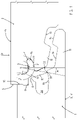
- figure 1 shows the cross section through the connection area of two panels 1, 2.
- the panels 1, 2 are configured in such a way that they can be assembled to form a covering, in particular a floor covering.
- the panels 1, 2 have an underside 3 facing the ground and an upper side 4, which corresponds to the visible side.
- the bottom 3 and the top 4 run parallel to a laying plane V.
- the second panel 2 has a locking element 6 in a guide groove 7 on the side 5 facing the first panel 1 .
- the locking element 6 is intended to grip behind a locking edge 8 on the first panel 1 or to grip under the locking edge 8 when viewed from above.
- the locking edge 8 is located below a bearing strip 9 which is designed as a projection on the side 10 of the first panel 1.
- the support bar 9 runs on the upper side parallel to the laying plane V. Other orientations of the upper side of the support bar 9 are possible.
- the top can z. B. run at an acute angle to the laying plane V.
- a corresponding recess is formed on the edge side 5 of the second panel 2, so that the second panel 2 is supported near its upper side 4 perpendicularly to the laying plane V on the first panel 1.
- the first panel 1 has a locking bar 11 .
- the locking strip 11 of the first panel 1 projects farthest from the side 10 of the first panel 1 .
- the second panel 2 has a downwardly open coupling channel 12 and an adjoining, downward-pointing coupling bead 13.
- the second panel 2 is arranged opposite the first panel 1 in such a way that when it is lowered in the direction of arrow P, the coupling bead 13 of the second panel 2 comes into contact with an upwardly open coupling channel 14 of the locking strip 11 and the coupling channel 12 of the second panel 2 engages a coupling bead 15 of the locking bar 11 .
- This area of the panels 1, 2 is used for the horizontal connection of the panels 1, 2.
- Laying down in the direction of the arrow P can take place in that the upper side 4 of the second panel 2 is displaced parallel to the V laying plane.
- the second panel 2 can be angled relative to the first panel 1 by pivoting (folding down) around another edge side.
- the coupling bead 15 on the locking strip 11 of the first panel 1 and the downwardly protruding coupling bead 13 on the second panel 2 each have a sloping top and bottom, so that even when the panels 1, 2 are pushed together in the direction of the laying plane V, the means that when pushed together horizontally, the coupling bead 13 of the second panel 2 slides on the coupling bead 15 of the first panel 1 that was laid first.
- the second panel 2 is thereby raised until the two panels 1 , 2 are guided over the highest point of the coupling bead 15 of the locking bar 11 .
- the second panel 2 then automatically slides into the coupling channel 14, which is open at the top, on the locking strip 11.
- the panels 1, 2 can therefore not only be connected to one another by laying them down vertically or by angling them in, but also by sliding them horizontally into one another in the direction of the laying plane V.
- the locking element 6 has a guide arm 16.
- the guide arm 16 is the part that in Guide groove 7 is arranged and the locking element 6 on the second panel 2 holds.
- the locking element 6 has a locking projection 17 which protrudes from the guide groove 7 .
- the locking projection 17 is the area in front of the guide arm 16 which is outside of the guide groove 7 .
- the locking element 6 has an essentially L- or Y-shaped cross section, since a leg 18 connects to the locking projection 17 downwards in the plane of the drawing.
- the leg 18 therefore does not protrude beyond the edge side 5 of the second panel 2 . In the initial position, it extends in the direction of the coupling bead 13 and lies against the second panel 2 .
- the leg 18 is provided for pivoting the locking element 6 and, when the second panel 2 is lowered in the direction of the arrow P, strikes a guide surface 19 which is located below the locking edge 8 on the first panel 1 .
- the guide surface 19 is concavely curved in this embodiment.
- the guide surface 19 is followed by a groove 20, which is open towards the edge side 10 and serves to accommodate a fixed spring tongue, as shown in Figure 5a is shown.
- the guide arm 16 is rigid, ie essentially rigidly connected to a leg 18 .
- the locking element 16 is guided in the guide groove 7 .
- the lower groove cheek 21 of the guide groove 7 is concavely curved.
- the guide groove 7 is even in the shape of a circular arc, as can be seen from the line L1.
- the line L1 describes a circle around a pivot point S, which is located above the guide groove 7.
- a line L2 describes a smaller radius, also around the pivot point S. It can be seen that the guide arm has a convexly curved underside 22, the curvature corresponding to the line L1 of the concave curvature of the lower groove cheek 21 of the guide groove 7.
- the guide arm 16 rests in the region of the opening of the guide groove 7 on the upper side of the upper groove cheek 23, with the opening area lying on the line L2. Accordingly, the locking element 6 is displaced along the two circular arcs (lines L1 and L2).
- the angle W1 indicates how far that Locking element is to be pivoted at least until both support strips 31, 32 come into contact with the guide surface 19.
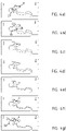
- the Figures 3a to g show the planned sequence of movements.
- the two panels 1, 2 are shown just before the locking element 6 comes into contact with the first panel 1.
- the leg 18 of the locking element 6 pushes it upwards, so that the guide arm 16 is pulled out of the guide groove 7 .
- the Figures 3c to 3f show the further course of this pivoting movement, until finally the locking position in Figure 3g is reached.
- the two panels 1, 2 are at the same height because the second panel 2 rests on the support strip 9 of the first panel 1.
- the bearing strip 9 is clamped between the locking element 6 and the second panel 2 resting on the upper side.
- the locking element 6 prevents the second panel 2 from being lifted off the first panel 1 vertically.
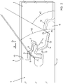
- FIG. 2 A slightly different possibility of the joining movement is shown in the illustration figure 2 .
- These are structurally identical components, as in the figures 1 and 3 , but horizontal and vertical movements are superimposed in this embodiment.
- the second panel 2 is lowered in the direction of the arrow P, ie vertically.
- the second panel 2 is also displaced horizontally in the direction of the arrow H, ie in the direction of the first panel 1, so that the edge sides 5, 10 of the panels 1, 2 abut.
- the panel 2 is shown in two different positions.
- the exact joining movement results from the contact between the coupling beads 15 and 13 in the transition area to their respective coupling grooves 12, 14.
- the angle W2 relative to the laying plane V is preferably 55 to 65°, in particular 60°.
- the second angle W2 drawn in indicates the angle relative to the laying plane V, which a locking surface 24 has, which is on the locking edge 8 connects.
- the locking projection 17 rests flat against the latching surface 24 .
- forces that act on the first panel 1 from above can be introduced over the surface into the locking element 6 via the latching surface 24 .
- the locking element 6 transmits these forces in turn via the Guide arm 7 onto the second panel.
- the guide arm 7 essentially points towards the coupling bead 15 of the first panel 1 and therefore presses the coupling bead 13 in the area of the supporting flank 25 onto the associated supporting flank 26 of the other panel.
- the arrow F in figure 7 shows the direction of action of this force.
- FIG. 4a to 4g show the sequence of movements analogous to the Figures 3a to g in the first-mentioned embodiment. It can be seen that a projection 28 is formed on the underside of the leg 18 and initially slides over the guide surface 19 .
- the guide surface 19 is not concave in this exemplary embodiment, but is straight but nevertheless slightly inclined with respect to the laying plane V to set the direction.
- the locking element 6 If the locking element 6 is pivoted far enough, the projection 28 engages in the locking recess 27 in the area of the lower groove flank of the groove 20. This causes the mechanical connection to be locked vertically. As a result, the locking element 6 should rest firmly against the first panel 1 in the region of the locking surface 24 even after the projection 28 has snapped into the locking recess 27, so that the panels 1, 2 are securely connected to one another.
- Both embodiments according to figure 3 and figure 4 cause the guide arm 16 to be pulled out of the guide groove 7 .
- the movement is in any case unidirectional, ie only directed away from the second panel 2 towards the first panel 1 . In both of these exemplary embodiments, it is a question of a pure rotational movement about a fixed pivot point S, which is located spatially within the second panel 2 .
- Figures 5a and 5b show the long side of panel 2 ( Figure 5a ) and the head side 5 of the panel 2 described above.
- Figure 6a shows the longitudinal edge side 29 of the panel 2, a fixed spring tongue 30 being arranged on this edge side 29.
- the spring tongue 30 is configured to match the groove 21 on the first panel 1.
- the Figures 6a and 6b show the assembly position.
- Figure 6b corresponds to the representation of the Figure 4g . It shows the mechanical connection between the panels 1, 2, preferably in the area of their top edge sides.
- the Figure 6a shows the connection of a longitudinal edge side 29 with a head side 10 of the first panel 1 for one and the same first panel 1.
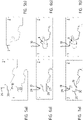
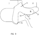
- figure 8 shows a vertical section through the edge area of two mutually engaging panels 1, 2 in two different positions of the locking element 6, in order to clarify the angle W1 through which the locking element 6 is to be pivoted for locking.
- the angle W1 is measured on a side facing away from the guide arm 16 and the side facing the groove 20 and is 20 to 35°. In this example between 25 and 30°.
- the design of the locking recess 27 and a projection 37 in the transition from the groove 20 to the locking surface 24 prevent the leg 18 further than in the figure 8 shown below in the direction of the groove 21 is displaceable.
- the figure 9 shows that the lower groove cheek 21 has a flat area 33 .
- This flat area 33 is located where the guide arm rests in the locked position.
- the flat area 33 runs parallel to the laying plane V.
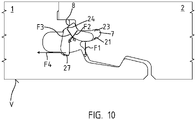
- figure 10 shows the corresponding force vectors.
- the arrow F1 shows the direction of the force which emanates from the guide arm 16 and presses on the lower groove cheek 21 of the guide groove 7.
- the arrow F2 shows the direction of the force which acts on the locking element 6 from the second panel 2, specifically in the region of the mouth of the groove of the upper groove cheek 23. The force is directed in the direction of the leg 18.
- the arrow F3 shows the direction of the force exerted by the first panel 1 on the locking element 6, namely perpendicular to the latching surface 24 below the locking edge 8. This force presses the guide arm 16 against the lower groove cheek 21 of the guide groove.
- the arrow F4 indicates that a force or force component acting essentially parallel to the laying plane V acts on the leg 18 in the region of the latching recess 27 . This exerts a torque on the guide arm 16, which in turn presses the second panel 2 down against the first panel 1 (arrow F1).
- the locking recess 27 has a support wall 34 ( figure 8 ), which encloses an angle between 45° and 90° with the laying plane V, ie is relatively steep and therefore enables the locking element 6 to engage securely.
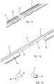
- the Figures 11 and 12 show ends 35, 36 of adjacent locking elements 6, in which the leg 18 has been removed in order to deform the guide arms 16 in these areas by embossing.
- the ends 35, 36 in the area of the guide arms 16 are corrugated.
- figure 13 shows a cross section through the locking element 16 outside the end area 35 on the left and the cross section inside the end area 35 on the right.
- the corrugation causes the guide arms 15 in the end areas 35, 36 to be thicker.
- the locking element 16 can be clamped in place in a guide groove 6 . Production is possible at low cost and can take place during the cutting to length of a profile that is provided in particular as an endless strand.
Landscapes
- Engineering & Computer Science (AREA)
- Mechanical Engineering (AREA)
- Architecture (AREA)
- General Engineering & Computer Science (AREA)
- Civil Engineering (AREA)
- Structural Engineering (AREA)
- Chemical & Material Sciences (AREA)
- Composite Materials (AREA)
- Floor Finish (AREA)
Applications Claiming Priority (2)
| Application Number | Priority Date | Filing Date | Title |
|---|---|---|---|
| DE102015121761.9A DE102015121761A1 (de) | 2015-12-14 | 2015-12-14 | Mechanische Verbindung für Paneele |
| PCT/DE2016/100586 WO2017101910A1 (de) | 2015-12-14 | 2016-12-14 | Mechanische verbindung für paneele |
Publications (2)
| Publication Number | Publication Date |
|---|---|
| EP3374579A1 EP3374579A1 (de) | 2018-09-19 |
| EP3374579B1 true EP3374579B1 (de) | 2022-05-11 |
Family
ID=57838091
Family Applications (1)
| Application Number | Title | Priority Date | Filing Date |
|---|---|---|---|
| EP16828703.5A Active EP3374579B1 (de) | 2015-12-14 | 2016-12-14 | Mechanische verbindung für paneele |
Country Status (5)
| Country | Link |
|---|---|
| US (1) | US11339815B2 (pl) |
| EP (1) | EP3374579B1 (pl) |
| DE (1) | DE102015121761A1 (pl) |
| PL (1) | PL3374579T3 (pl) |
| WO (1) | WO2017101910A1 (pl) |
Families Citing this family (7)
| Publication number | Priority date | Publication date | Assignee | Title |
|---|---|---|---|---|
| CA3042373C (en) | 2010-01-11 | 2021-07-06 | Valinge Innovation Ab | Floor covering with interlocking design |
| CN107190946B (zh) | 2013-03-25 | 2020-06-05 | 瓦林格创新股份有限公司 | 具有机械锁定系统的地板块以及这种锁定系统的生产方法 |
| EP4219860A1 (en) | 2014-08-29 | 2023-08-02 | Välinge Innovation AB | Vertical joint system for a surface covering panel |
| EP3390744B1 (en) * | 2015-12-17 | 2024-08-21 | Välinge Innovation AB | A method for producing a mechanical locking system for panels |
| WO2018063047A1 (en) | 2016-09-30 | 2018-04-05 | Välinge Innovation AB | Set of panels assembled by vertical displacement and locked together in the vertical and horizontal direction |
| PT3737802T (pt) | 2018-01-09 | 2023-07-19 | Vaelinge Innovation Ab | Conjunto de painéis |
| PL3892793T3 (pl) * | 2020-04-08 | 2024-03-25 | Akzenta Paneele + Profile Gmbh | Panel z niełamalnymi elementami sprzęgającymi |
Family Cites Families (10)
| Publication number | Priority date | Publication date | Assignee | Title |
|---|---|---|---|---|
| SE531111C2 (sv) * | 2006-12-08 | 2008-12-23 | Vaelinge Innovation Ab | Mekanisk låsning av golvpaneler |
| US7726088B2 (en) * | 2007-07-20 | 2010-06-01 | Moritz Andre Muehlebach | Flooring system |
| US8220217B2 (en) * | 2007-07-20 | 2012-07-17 | Innovaris Ag | Flooring system |
| BE1018600A5 (nl) * | 2007-11-23 | 2011-04-05 | Flooring Ind Ltd Sarl | Vloerpaneel. |
| DE102009022483A1 (de) * | 2009-05-25 | 2010-12-02 | Pergo (Europe) Ab | Set von Paneelen, insbesondere von Fußbodenpaneelen |
| DE102009034902B4 (de) * | 2009-07-27 | 2015-10-01 | Guido Schulte | Belag aus mechanisch miteinander verbindbaren Paneelen |
| DE102009041297B4 (de) | 2009-09-15 | 2018-10-11 | Guido Schulte | Belag aus mechanisch miteinander verbindbaren Elementen und ein Verfahren zur Herstellung von Elementen |
| DE102012105793A1 (de) | 2011-07-29 | 2013-01-31 | Hamberger Industriewerke Gmbh | Verbindung für elastische oder plattenförmige Bauelemente und Fußbodenbelag |
| EP2674546A1 (de) | 2012-06-11 | 2013-12-18 | Falquon GmbH | System zum Verbinden und Verriegeln zweier Bauplatten |
| DE102013112550A1 (de) * | 2013-08-07 | 2015-02-12 | Hamberger Industriewerke Gmbh | Verbindung für plattenförmige Bauelemente |
-
2015
- 2015-12-14 DE DE102015121761.9A patent/DE102015121761A1/de not_active Withdrawn
-
2016
- 2016-12-14 PL PL16828703.5T patent/PL3374579T3/pl unknown
- 2016-12-14 EP EP16828703.5A patent/EP3374579B1/de active Active
- 2016-12-14 US US16/061,822 patent/US11339815B2/en active Active
- 2016-12-14 WO PCT/DE2016/100586 patent/WO2017101910A1/de not_active Ceased
Also Published As
| Publication number | Publication date |
|---|---|
| PL3374579T3 (pl) | 2022-09-19 |
| DE102015121761A1 (de) | 2017-06-14 |
| US20200263714A1 (en) | 2020-08-20 |
| WO2017101910A1 (de) | 2017-06-22 |
| US11339815B2 (en) | 2022-05-24 |
| EP3374579A1 (de) | 2018-09-19 |
Similar Documents
| Publication | Publication Date | Title |
|---|---|---|
| EP3374579B1 (de) | Mechanische verbindung für paneele | |
| DE102009034903B3 (de) | Belag aus mechanisch miteinander verbindbaren Paneelen | |
| EP3121348B1 (de) | Paneel | |
| EP3298212B1 (de) | Belag von im verbund verlegten rechteckigen oder quadratischen paneelen | |
| EP2057327B1 (de) | Paneel, insbesondere bodenpaneel | |
| DE102012105793A1 (de) | Verbindung für elastische oder plattenförmige Bauelemente und Fußbodenbelag | |
| EP1165906A1 (de) | Paneel sowie befestigungssystem für paneele | |
| DE102012102339A1 (de) | Verbindung für elastische oder plattenförmige Bauelemente, Profilschieber und Fußbodenbelag | |
| DE102008021970B4 (de) | Paneel mit vereinfachtem Rastelement | |
| DE20203311U1 (de) | Paneelelement | |
| EP2333195A1 (de) | Fußboden, erstellt aus Fußbodenpaneelen mit separaten Verbindungsmitteln und Verfahren zur Verlegung von Fußbodenpaneelen | |
| EP3117055B1 (de) | Belag aus mechanisch miteinander verbindbaren paneelen | |
| EP1900889A2 (de) | Fussbodenpaneel | |
| EP3271527B1 (de) | Mechanische verbindung für paneele und verfahren zur herstellung von verbindungsmitteln | |
| DE10242647B4 (de) | Paneel | |
| DE202015008925U1 (de) | Mechanische Verbindung für Paneele | |
| EP2795016B1 (de) | Paneel eines fussbodenbelags mit fremdelement | |
| DE202016105667U1 (de) | Paneel und mechanische Paneelverbindung | |
| EP2885470B1 (de) | Belag aus mechanisch miteinander verbindbaren elementen | |
| DE102015102671B4 (de) | Paneele mit einer mechanischen Verbindung für diese Paneele, Verfahren zur Montage einer Verriegelungsfeder in einem Paneel und Verfahren zum Verbinden von Paneelen mit einer mechanischen Verbindung | |
| EP3080365A1 (de) | Paneel mit verriegelungselement | |
| DE20200268U1 (de) | Paneelelement | |
| EP3309322A1 (de) | Paneel und mechanische paneelverbindung | |
| DE202017101029U1 (de) | Paneel und mechanische Paneelverbindung | |
| DE102016114226A1 (de) | Verbindung für elastische oder feste Bauelemente |
Legal Events
| Date | Code | Title | Description |
|---|---|---|---|
| STAA | Information on the status of an ep patent application or granted ep patent |
Free format text: STATUS: UNKNOWN |
|
| STAA | Information on the status of an ep patent application or granted ep patent |
Free format text: STATUS: THE INTERNATIONAL PUBLICATION HAS BEEN MADE |
|
| PUAI | Public reference made under article 153(3) epc to a published international application that has entered the european phase |
Free format text: ORIGINAL CODE: 0009012 |
|
| STAA | Information on the status of an ep patent application or granted ep patent |
Free format text: STATUS: REQUEST FOR EXAMINATION WAS MADE |
|
| 17P | Request for examination filed |
Effective date: 20180612 |
|
| AK | Designated contracting states |
Kind code of ref document: A1 Designated state(s): AL AT BE BG CH CY CZ DE DK EE ES FI FR GB GR HR HU IE IS IT LI LT LU LV MC MK MT NL NO PL PT RO RS SE SI SK SM TR |
|
| AX | Request for extension of the european patent |
Extension state: BA ME |
|
| RIN1 | Information on inventor provided before grant (corrected) |
Inventor name: SCHULTE, GUIDO Inventor name: ESCHLBECK, FRANZ-JOSEF |
|
| DAV | Request for validation of the european patent (deleted) | ||
| DAX | Request for extension of the european patent (deleted) | ||
| GRAP | Despatch of communication of intention to grant a patent |
Free format text: ORIGINAL CODE: EPIDOSNIGR1 |
|
| STAA | Information on the status of an ep patent application or granted ep patent |
Free format text: STATUS: GRANT OF PATENT IS INTENDED |
|
| INTG | Intention to grant announced |
Effective date: 20220111 |
|
| RAP3 | Party data changed (applicant data changed or rights of an application transferred) |
Owner name: SCHULTE, GUIDO |
|
| GRAS | Grant fee paid |
Free format text: ORIGINAL CODE: EPIDOSNIGR3 |
|
| GRAA | (expected) grant |
Free format text: ORIGINAL CODE: 0009210 |
|
| STAA | Information on the status of an ep patent application or granted ep patent |
Free format text: STATUS: THE PATENT HAS BEEN GRANTED |
|
| AK | Designated contracting states |
Kind code of ref document: B1 Designated state(s): AL AT BE BG CH CY CZ DE DK EE ES FI FR GB GR HR HU IE IS IT LI LT LU LV MC MK MT NL NO PL PT RO RS SE SI SK SM TR |
|
| REG | Reference to a national code |
Ref country code: GB Ref legal event code: FG4D Free format text: NOT ENGLISH |
|
| REG | Reference to a national code |
Ref country code: CH Ref legal event code: EP |
|
| REG | Reference to a national code |
Ref country code: AT Ref legal event code: REF Ref document number: 1491532 Country of ref document: AT Kind code of ref document: T Effective date: 20220515 |
|
| REG | Reference to a national code |
Ref country code: DE Ref legal event code: R096 Ref document number: 502016014888 Country of ref document: DE |
|
| REG | Reference to a national code |
Ref country code: IE Ref legal event code: FG4D Free format text: LANGUAGE OF EP DOCUMENT: GERMAN |
|
| REG | Reference to a national code |
Ref country code: LT Ref legal event code: MG9D |
|
| REG | Reference to a national code |
Ref country code: NL Ref legal event code: MP Effective date: 20220511 |
|
| PG25 | Lapsed in a contracting state [announced via postgrant information from national office to epo] |
Ref country code: SE Free format text: LAPSE BECAUSE OF FAILURE TO SUBMIT A TRANSLATION OF THE DESCRIPTION OR TO PAY THE FEE WITHIN THE PRESCRIBED TIME-LIMIT Effective date: 20220511 Ref country code: PT Free format text: LAPSE BECAUSE OF FAILURE TO SUBMIT A TRANSLATION OF THE DESCRIPTION OR TO PAY THE FEE WITHIN THE PRESCRIBED TIME-LIMIT Effective date: 20220912 Ref country code: NO Free format text: LAPSE BECAUSE OF FAILURE TO SUBMIT A TRANSLATION OF THE DESCRIPTION OR TO PAY THE FEE WITHIN THE PRESCRIBED TIME-LIMIT Effective date: 20220811 Ref country code: NL Free format text: LAPSE BECAUSE OF FAILURE TO SUBMIT A TRANSLATION OF THE DESCRIPTION OR TO PAY THE FEE WITHIN THE PRESCRIBED TIME-LIMIT Effective date: 20220511 Ref country code: LT Free format text: LAPSE BECAUSE OF FAILURE TO SUBMIT A TRANSLATION OF THE DESCRIPTION OR TO PAY THE FEE WITHIN THE PRESCRIBED TIME-LIMIT Effective date: 20220511 Ref country code: HR Free format text: LAPSE BECAUSE OF FAILURE TO SUBMIT A TRANSLATION OF THE DESCRIPTION OR TO PAY THE FEE WITHIN THE PRESCRIBED TIME-LIMIT Effective date: 20220511 Ref country code: GR Free format text: LAPSE BECAUSE OF FAILURE TO SUBMIT A TRANSLATION OF THE DESCRIPTION OR TO PAY THE FEE WITHIN THE PRESCRIBED TIME-LIMIT Effective date: 20220812 Ref country code: FI Free format text: LAPSE BECAUSE OF FAILURE TO SUBMIT A TRANSLATION OF THE DESCRIPTION OR TO PAY THE FEE WITHIN THE PRESCRIBED TIME-LIMIT Effective date: 20220511 Ref country code: ES Free format text: LAPSE BECAUSE OF FAILURE TO SUBMIT A TRANSLATION OF THE DESCRIPTION OR TO PAY THE FEE WITHIN THE PRESCRIBED TIME-LIMIT Effective date: 20220511 Ref country code: BG Free format text: LAPSE BECAUSE OF FAILURE TO SUBMIT A TRANSLATION OF THE DESCRIPTION OR TO PAY THE FEE WITHIN THE PRESCRIBED TIME-LIMIT Effective date: 20220811 |
|
| PG25 | Lapsed in a contracting state [announced via postgrant information from national office to epo] |
Ref country code: RS Free format text: LAPSE BECAUSE OF FAILURE TO SUBMIT A TRANSLATION OF THE DESCRIPTION OR TO PAY THE FEE WITHIN THE PRESCRIBED TIME-LIMIT Effective date: 20220511 Ref country code: LV Free format text: LAPSE BECAUSE OF FAILURE TO SUBMIT A TRANSLATION OF THE DESCRIPTION OR TO PAY THE FEE WITHIN THE PRESCRIBED TIME-LIMIT Effective date: 20220511 Ref country code: IS Free format text: LAPSE BECAUSE OF FAILURE TO SUBMIT A TRANSLATION OF THE DESCRIPTION OR TO PAY THE FEE WITHIN THE PRESCRIBED TIME-LIMIT Effective date: 20220911 |
|
| PG25 | Lapsed in a contracting state [announced via postgrant information from national office to epo] |
Ref country code: SM Free format text: LAPSE BECAUSE OF FAILURE TO SUBMIT A TRANSLATION OF THE DESCRIPTION OR TO PAY THE FEE WITHIN THE PRESCRIBED TIME-LIMIT Effective date: 20220511 Ref country code: SK Free format text: LAPSE BECAUSE OF FAILURE TO SUBMIT A TRANSLATION OF THE DESCRIPTION OR TO PAY THE FEE WITHIN THE PRESCRIBED TIME-LIMIT Effective date: 20220511 Ref country code: RO Free format text: LAPSE BECAUSE OF FAILURE TO SUBMIT A TRANSLATION OF THE DESCRIPTION OR TO PAY THE FEE WITHIN THE PRESCRIBED TIME-LIMIT Effective date: 20220511 Ref country code: EE Free format text: LAPSE BECAUSE OF FAILURE TO SUBMIT A TRANSLATION OF THE DESCRIPTION OR TO PAY THE FEE WITHIN THE PRESCRIBED TIME-LIMIT Effective date: 20220511 Ref country code: DK Free format text: LAPSE BECAUSE OF FAILURE TO SUBMIT A TRANSLATION OF THE DESCRIPTION OR TO PAY THE FEE WITHIN THE PRESCRIBED TIME-LIMIT Effective date: 20220511 Ref country code: CZ Free format text: LAPSE BECAUSE OF FAILURE TO SUBMIT A TRANSLATION OF THE DESCRIPTION OR TO PAY THE FEE WITHIN THE PRESCRIBED TIME-LIMIT Effective date: 20220511 |
|
| PGFP | Annual fee paid to national office [announced via postgrant information from national office to epo] |
Ref country code: FR Payment date: 20221222 Year of fee payment: 7 |
|
| REG | Reference to a national code |
Ref country code: DE Ref legal event code: R097 Ref document number: 502016014888 Country of ref document: DE |
|
| PGFP | Annual fee paid to national office [announced via postgrant information from national office to epo] |
Ref country code: PL Payment date: 20221206 Year of fee payment: 7 |
|
| PLBE | No opposition filed within time limit |
Free format text: ORIGINAL CODE: 0009261 |
|
| STAA | Information on the status of an ep patent application or granted ep patent |
Free format text: STATUS: NO OPPOSITION FILED WITHIN TIME LIMIT |
|
| PG25 | Lapsed in a contracting state [announced via postgrant information from national office to epo] |
Ref country code: AL Free format text: LAPSE BECAUSE OF FAILURE TO SUBMIT A TRANSLATION OF THE DESCRIPTION OR TO PAY THE FEE WITHIN THE PRESCRIBED TIME-LIMIT Effective date: 20220511 |
|
| 26N | No opposition filed |
Effective date: 20230214 |
|
| PG25 | Lapsed in a contracting state [announced via postgrant information from national office to epo] |
Ref country code: SI Free format text: LAPSE BECAUSE OF FAILURE TO SUBMIT A TRANSLATION OF THE DESCRIPTION OR TO PAY THE FEE WITHIN THE PRESCRIBED TIME-LIMIT Effective date: 20220511 |
|
| REG | Reference to a national code |
Ref country code: CH Ref legal event code: PL |
|
| GBPC | Gb: european patent ceased through non-payment of renewal fee |
Effective date: 20221214 |
|
| REG | Reference to a national code |
Ref country code: BE Ref legal event code: MM Effective date: 20221231 |
|
| PG25 | Lapsed in a contracting state [announced via postgrant information from national office to epo] |
Ref country code: LU Free format text: LAPSE BECAUSE OF NON-PAYMENT OF DUE FEES Effective date: 20221214 |
|
| PG25 | Lapsed in a contracting state [announced via postgrant information from national office to epo] |
Ref country code: LI Free format text: LAPSE BECAUSE OF NON-PAYMENT OF DUE FEES Effective date: 20221231 Ref country code: IE Free format text: LAPSE BECAUSE OF NON-PAYMENT OF DUE FEES Effective date: 20221214 Ref country code: GB Free format text: LAPSE BECAUSE OF NON-PAYMENT OF DUE FEES Effective date: 20221214 Ref country code: CH Free format text: LAPSE BECAUSE OF NON-PAYMENT OF DUE FEES Effective date: 20221231 |
|
| PG25 | Lapsed in a contracting state [announced via postgrant information from national office to epo] |
Ref country code: BE Free format text: LAPSE BECAUSE OF NON-PAYMENT OF DUE FEES Effective date: 20221231 |
|
| PG25 | Lapsed in a contracting state [announced via postgrant information from national office to epo] |
Ref country code: IT Free format text: LAPSE BECAUSE OF FAILURE TO SUBMIT A TRANSLATION OF THE DESCRIPTION OR TO PAY THE FEE WITHIN THE PRESCRIBED TIME-LIMIT Effective date: 20220511 |
|
| REG | Reference to a national code |
Ref country code: AT Ref legal event code: MM01 Ref document number: 1491532 Country of ref document: AT Kind code of ref document: T Effective date: 20221214 |
|
| PG25 | Lapsed in a contracting state [announced via postgrant information from national office to epo] |
Ref country code: HU Free format text: LAPSE BECAUSE OF FAILURE TO SUBMIT A TRANSLATION OF THE DESCRIPTION OR TO PAY THE FEE WITHIN THE PRESCRIBED TIME-LIMIT; INVALID AB INITIO Effective date: 20161214 |
|
| PG25 | Lapsed in a contracting state [announced via postgrant information from national office to epo] |
Ref country code: AT Free format text: LAPSE BECAUSE OF NON-PAYMENT OF DUE FEES Effective date: 20221214 |
|
| PG25 | Lapsed in a contracting state [announced via postgrant information from national office to epo] |
Ref country code: CY Free format text: LAPSE BECAUSE OF FAILURE TO SUBMIT A TRANSLATION OF THE DESCRIPTION OR TO PAY THE FEE WITHIN THE PRESCRIBED TIME-LIMIT Effective date: 20220511 Ref country code: AT Free format text: LAPSE BECAUSE OF NON-PAYMENT OF DUE FEES Effective date: 20221214 |
|
| PG25 | Lapsed in a contracting state [announced via postgrant information from national office to epo] |
Ref country code: MK Free format text: LAPSE BECAUSE OF FAILURE TO SUBMIT A TRANSLATION OF THE DESCRIPTION OR TO PAY THE FEE WITHIN THE PRESCRIBED TIME-LIMIT Effective date: 20220511 |
|
| PG25 | Lapsed in a contracting state [announced via postgrant information from national office to epo] |
Ref country code: MC Free format text: LAPSE BECAUSE OF FAILURE TO SUBMIT A TRANSLATION OF THE DESCRIPTION OR TO PAY THE FEE WITHIN THE PRESCRIBED TIME-LIMIT Effective date: 20220511 |
|
| PG25 | Lapsed in a contracting state [announced via postgrant information from national office to epo] |
Ref country code: TR Free format text: LAPSE BECAUSE OF FAILURE TO SUBMIT A TRANSLATION OF THE DESCRIPTION OR TO PAY THE FEE WITHIN THE PRESCRIBED TIME-LIMIT Effective date: 20220511 Ref country code: MC Free format text: LAPSE BECAUSE OF FAILURE TO SUBMIT A TRANSLATION OF THE DESCRIPTION OR TO PAY THE FEE WITHIN THE PRESCRIBED TIME-LIMIT Effective date: 20220511 |
|
| PG25 | Lapsed in a contracting state [announced via postgrant information from national office to epo] |
Ref country code: MT Free format text: LAPSE BECAUSE OF FAILURE TO SUBMIT A TRANSLATION OF THE DESCRIPTION OR TO PAY THE FEE WITHIN THE PRESCRIBED TIME-LIMIT Effective date: 20220511 |
|
| PG25 | Lapsed in a contracting state [announced via postgrant information from national office to epo] |
Ref country code: FR Free format text: LAPSE BECAUSE OF NON-PAYMENT OF DUE FEES Effective date: 20231231 |
|
| PG25 | Lapsed in a contracting state [announced via postgrant information from national office to epo] |
Ref country code: FR Free format text: LAPSE BECAUSE OF NON-PAYMENT OF DUE FEES Effective date: 20231231 |
|
| PG25 | Lapsed in a contracting state [announced via postgrant information from national office to epo] |
Ref country code: BG Free format text: LAPSE BECAUSE OF FAILURE TO SUBMIT A TRANSLATION OF THE DESCRIPTION OR TO PAY THE FEE WITHIN THE PRESCRIBED TIME-LIMIT Effective date: 20220511 |
|
| PG25 | Lapsed in a contracting state [announced via postgrant information from national office to epo] |
Ref country code: BG Free format text: LAPSE BECAUSE OF FAILURE TO SUBMIT A TRANSLATION OF THE DESCRIPTION OR TO PAY THE FEE WITHIN THE PRESCRIBED TIME-LIMIT Effective date: 20220511 |
|
| PGFP | Annual fee paid to national office [announced via postgrant information from national office to epo] |
Ref country code: DE Payment date: 20241219 Year of fee payment: 9 |
|
| PG25 | Lapsed in a contracting state [announced via postgrant information from national office to epo] |
Ref country code: PL Free format text: LAPSE BECAUSE OF NON-PAYMENT OF DUE FEES Effective date: 20231214 |