EP3370596B1 - Netzhautbilderfassung - Google Patents
Netzhautbilderfassung Download PDFInfo
- Publication number
- EP3370596B1 EP3370596B1 EP16862740.4A EP16862740A EP3370596B1 EP 3370596 B1 EP3370596 B1 EP 3370596B1 EP 16862740 A EP16862740 A EP 16862740A EP 3370596 B1 EP3370596 B1 EP 3370596B1
- Authority
- EP
- European Patent Office
- Prior art keywords
- fundus
- images
- capture
- image
- patient
- Prior art date
- Legal status (The legal status is an assumption and is not a legal conclusion. Google has not performed a legal analysis and makes no representation as to the accuracy of the status listed.)
- Active
Links
Images


Classifications
-
- A—HUMAN NECESSITIES
- A61—MEDICAL OR VETERINARY SCIENCE; HYGIENE
- A61B—DIAGNOSIS; SURGERY; IDENTIFICATION
- A61B3/00—Apparatus for testing the eyes; Instruments for examining the eyes
- A61B3/0016—Operational features thereof
- A61B3/0025—Operational features thereof characterised by electronic signal processing, e.g. eye models
-
- A—HUMAN NECESSITIES
- A61—MEDICAL OR VETERINARY SCIENCE; HYGIENE
- A61B—DIAGNOSIS; SURGERY; IDENTIFICATION
- A61B3/00—Apparatus for testing the eyes; Instruments for examining the eyes
- A61B3/0016—Operational features thereof
- A61B3/0033—Operational features thereof characterised by user input arrangements
-
- A—HUMAN NECESSITIES
- A61—MEDICAL OR VETERINARY SCIENCE; HYGIENE
- A61B—DIAGNOSIS; SURGERY; IDENTIFICATION
- A61B3/00—Apparatus for testing the eyes; Instruments for examining the eyes
- A61B3/0016—Operational features thereof
- A61B3/0041—Operational features thereof characterised by display arrangements
- A61B3/0058—Operational features thereof characterised by display arrangements for multiple images
-
- A—HUMAN NECESSITIES
- A61—MEDICAL OR VETERINARY SCIENCE; HYGIENE
- A61B—DIAGNOSIS; SURGERY; IDENTIFICATION
- A61B3/00—Apparatus for testing the eyes; Instruments for examining the eyes
- A61B3/10—Objective types, i.e. instruments for examining the eyes independent of the patients' perceptions or reactions
- A61B3/12—Objective types, i.e. instruments for examining the eyes independent of the patients' perceptions or reactions for looking at the eye fundus, e.g. ophthalmoscopes
-
- A—HUMAN NECESSITIES
- A61—MEDICAL OR VETERINARY SCIENCE; HYGIENE
- A61B—DIAGNOSIS; SURGERY; IDENTIFICATION
- A61B3/00—Apparatus for testing the eyes; Instruments for examining the eyes
- A61B3/10—Objective types, i.e. instruments for examining the eyes independent of the patients' perceptions or reactions
- A61B3/14—Arrangements specially adapted for eye photography
-
- G—PHYSICS
- G06—COMPUTING OR CALCULATING; COUNTING
- G06T—IMAGE DATA PROCESSING OR GENERATION, IN GENERAL
- G06T7/00—Image analysis
- G06T7/0002—Inspection of images, e.g. flaw detection
- G06T7/0012—Biomedical image inspection
Definitions
- diabetic retinopathy which is damage to the blood vessels of the light-sensitive tissue at the back of the eye, known as the retina.
- Trained medical professionals use cameras during eye examinations for diabetic retinopathy screening. The cameras can produce images of the back of the eye and trained medical professionals use those images to diagnose and treat diabetic retinopathy.
- the eye imaging apparatus comprises a light source, an image sensor, a hand-held computing device, and an adaptation module.
- the adaptation module comprises a microcontroller and a signal processing unit configured to adapt the hand-held computing device to control the light source and the image sensor.
- the eye imaging apparatus may be used in an eye imaging medical system. The images of the eye may be captured by the eye imaging apparatus, transferred to an image computing module, stored in an image storage module, and displayed in an image review module.
- an apparatus for producing a fundus image as recited in claim 1 includes: a processor and a memory; an illumination component including a light source and operatively coupled to the processor; a camera including a lens and operatively coupled to the processor, wherein the memory stores instructions that, when executed by the processor, cause the apparatus to: execute an automated script for capture of the fundus image; and allow for manual capture of the fundus image.
- a method for capturing one or more images of a fundus of a patient as recited in claim 7 includes: capturing specific images of the fundus using an apparatus; automatically uploading the specific images of the fundus to an over read service; and receiving feedback on a quality of one or more of the specific images of the fundus.
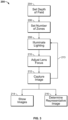
- FIG. 1 is a schematic block diagram illustrating an example system 100 for recording and viewing an image of a patient's fundus.
- the system 100 includes a patient P, a fundus imaging system 102, a computing device 1800 including an image processor 106, a camera 104 in communication with the computing device 1800, a display 108 in communication with the computing device 1800 and used by clinician C, and a network 110.
- An embodiment of the example fundus imaging system 102 is shown and described in more detail below with reference to FIG. 4 .
- the fundus imaging system 102 functions to create a set of digital images of a patient's P eye fundus.
- fundus refers to the eye fundus and includes the retina, optic nerve, macula, vitreous, choroid and posterior pole.
- one or more images of the eye are desired.
- the patient P is being screened for an eye disease, such as diabetic retinopathy.
- the fundus imaging system 102 can also be used to provide images of the eye for other purposes, such as to diagnose or monitor the progression of a disease such as diabetic retinopathy.
- the fundus imaging system 102 includes a handheld housing that supports the system's components.
- the housing supports one or two apertures for imaging one or two eyes at a time.
- the housing supports positional guides for the patient P, such as an optional adjustable chin rest. The positional guide or guides help to align the patient's P eye or eyes with the one or two apertures.
- the housing supports means for raising and lowering the one or more apertures to align them with the patient's P eye or eyes. Once the patient's P eyes are aligned, the clinician C then initiates the image captures by the fundus imaging system 102.
- Example system 100 does not require a mydriatic drug to be administered to the patient P before imaging, although the system 100 can image the fundus if a mydriatic drug has been administered.
- the system 100 can be used to assist the clinician C in screening for, monitoring, or diagnosing various eye diseases, such as hypertension, diabetic retinopathy, glaucoma and papilledema. It will be appreciated that the clinician C that operates the fundus imaging system 102 can be different from the clinician C evaluating the resulting image.
- the fundus imaging system 102 includes a camera 104 in communication with an image processor 106.
- the camera 104 is a digital camera including a lens, an aperture, and a sensor array.
- the camera 104 lens is a variable focus lens, such as a lens moved by a step motor, or a fluid lens, also known as a liquid lens in the art.
- the camera 104 is configured to record images of the fundus one eye at a time. In other embodiments, the camera 104 is configured to record an image of both eyes substantially simultaneously.
- the fundus imaging system 102 can include two separate cameras, one for each eye.
- the image processor 106 is operatively coupled to the camera 104 and configured to communicate with the network 110 and display 108.
- the image processor 106 regulates the operation of the camera 104.
- Components of an example computing device, including an image processor, are shown in more detail in FIG. 7 , which is described further below.
- the display 108 is in communication with the image processor 106.
- the housing supports the display 108.
- the display connects to the image processor, such as a smart phone, tablet computer, or external monitor.
- the display 108 functions to reproduce the images produced by the fundus imaging system 102 in a size and format readable by the clinician C.
- the display 108 can be a liquid crystal display (LCD) and active matrix organic light emitting diode (AMOLED) display.
- the display can be touch sensitive.
- the example fundus imaging system 102 is connected to a network 110.
- the network 110 may include any type of wireless network, a wired network, or any communication network known in the art.
- wireless connections can include cellular network connections and connections made using protocols such as 802.11a, b, and/or g.
- a wireless connection can be accomplished directly between the fundus imaging system 102 and an external display using one or more wired or wireless protocols, such as Bluetooth, Wi-Fi Direct, radiofrequency identification (RFID), or Zigbee. Other configurations are possible.
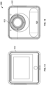
- FIG. 2 illustrates components of an example fundus imaging system 102.
- the example fundus imaging system 102 includes a variable focus lens 180, an illumination LED 182, an image sensor array 186, a fixation LED 184, a computing device 1800, and a display 108. Each component is in electrical communication with, at least, the computing device 1800. Other embodiments can include more or fewer components.
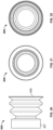
- variable focus lens 180 is a liquid lens.
- a liquid lens is an optical lens whose focal length can be controlled by the application of an external force, such as a voltage.
- the lens includes a transparent fluid, such as water or water and oil, sealed within a cell and a transparent membrane. By applying a force to the fluid, the curvature of the fluid changes, thereby changing the focal length. This effect is known as electrowetting.
- variable focus lens 180 is one or more movable lenses that are controlled by a stepping motor, a voice coil, an ultrasonic motor, or a piezoelectric actuator. Additionally, a stepping motor can also move the image sensor array 186. In those embodiments, the variable focus lens 180 and/or the image sensor array 186 are oriented normal to an optical axis of the fundus imaging system 102 and move along the optical axis.
- An example stepping motor is shown and described below with reference to FIG. 4 .
- the illumination LED 182 is in electrical communication with the computing device 1800. Thus, the illumination of illumination LED 182 is coordinated with the adjustment of the variable focus lens 180 and image capture.
- the illumination LED 182 can be overdriven to draw more than the maximum standard current draw rating.
- the illumination LED 182 can also include a near-infrared LED. The near-infrared LED is illuminated during a preview mode.
- the image sensor array 186 has a plurality of rows of pixels and a plurality of columns of pixels. In some embodiments, the image sensor array has about 1280 by 1024 pixels, about 640 by 480 pixels, about 1500 by 1152 pixels, about 2048 by 1536 pixels, or about 2560 by 1920 pixels.
- the pixel size in the image sensor array 186 is from about four micrometers by about four micrometers; from about two micrometers by about two micrometers; from about six micrometers by about six micrometers; or from about one micrometer by about one micrometer.
- the example image sensor array 186 includes photodiodes that have a light-receiving surface and have substantially uniform length and width. During exposure, the photodiodes convert the incident light to a charge.
- the image sensor array 186 can be operated as a global reset, that is, substantially all of the photodiodes are exposed simultaneously and for substantially identical lengths of time.
- the example fundus imaging system 102 also includes a display 108, discussed in more detail above with reference to FIG. 1 . Additionally, the example fundus imaging system 102 includes a computing device 1800, discussed in more detail below with reference to FIG. 7 .
- FIG. 3 is an embodiment of a method 200 for imaging a patient's fundus using a fundus imaging system.
- the lighting is optimally dimmed prior to execution, although lowering the lighting is optional.
- the embodiment shown includes a set depth of field operation 204, a set number of zones operation 206, an illuminate lighting operation 208, an adjust lens focus operation 210, a capture image operation 212, repeat operation(s) 213, a show images operation 214 and a determine representative image operation 216.
- Other embodiments can include more or fewer steps.
- the embodiment of method 200 begins with setting a depth of field operation 204.
- the variable focus lens 180 is capable of focusing from about -20 diopters to about +20 diopters.
- Set depth of field operation 204 defines the lower and upper bounds in terms of diopters.
- the depth of field range could be set to about -10 to + 10 diopters; about -5 to about +5 diopters; about -10 to about +20 diopters; about -5 to about +20 diopters; about - 20 to about +0 diopters; or about -5 to about +5 diopters.
- Other settings are possible.
- the depth of field can be preprogrammed by the manufacturer. Alternatively, the end user, such as the clinician C, can set the depth of field.
- the next operation in embodiment of method 200 is setting the number of zones operation 206.
- zones operation 206 can occur before or concurrent with field operation 204.
- the depth of field is divided into equal parts, where each part is called a zone.
- the zones are not all equal.
- the number of zones is equal to the number of images captured in capture image operation 212.
- the focus of the variable focus lens can be changed by 4 diopters before each image capture.
- images would be captured at -10, -6, -2, +2, +6 and + 10 diopters.
- images could be captured at -8, -4, 0, +4 and +8 diopters, thereby capturing an image in zones -10 to -6 diopters, - 6 to -2 diopters, -2 to +2 diopters, +2 to +6 diopters and +6 to +10 diopters, respectively.
- the depth of focus is about +/- 2 diopters.
- the number of zones and the depth of field can vary, resulting in different ranges of depth of field image capture.
- both depth of field and number of zones are predetermined. For example, -10D to + 10D and 5 zones. Both can be changed by a user.
- the next operation in embodiment of method 200 is the image capture process, which includes illuminate lighting operation 208, adjust lens focus operation 210 and capture image operation 212.
- the lighting component is illuminated (lighting operation 208) before the lens focus is adjusted (lens focus operation 210).
- lens focus operation 210 can occur before or concurrent with lighting operation 208.
- the illumination LED 182 is illuminated in lighting operation 208.
- the illumination LED 182 can remain illuminated throughout the duration of each image capture.
- the illumination LED 182 can be turned on and off for each image capture.
- the illumination LED 182 only turns on for the same period of time as the image sensor array 186 exposure time period.
- lighting operation 208 can additionally include illuminating a near-infrared LED.
- the clinician C can use the illumination of the near-infrared LED as a way to preview the position of the patient's P pupil.
- the focus of variable focus lens 180 is adjusted in lens focus operation 210.
- Autofocusing is not used in embodiment of method 200. That is, the diopter setting is provided to the lens without regard to the quality of the focus of the image. Indeed, traditional autofocusing fails in the low-lighting non-mydriatic image capturing environment.
- the embodiment of method 200 results in a plurality of images at least one of which, or a combination of which, yields an in-focus view of the patient's P fundus.
- variable focus lens 180 can be set to a particular diopter range and an image captured without the system verifying that the particular focus level will produce an in-focus image, as is found in autofocusing systems. Because the system does not attempt to autofocus, and the focus of the variable focus lens 180 can be altered in roughly tens of milliseconds, images can be captured throughout the depth of field in well under a second, in embodiments.
- the fundus imaging system 102 can capture images of the entire depth of field before the patient's P eye can react to the illuminated light. Without being bound to a particular theory, depending on the patient P, the eye might react to the light from illumination LED 182 in about 150 milliseconds.
- the image sensor array 186 captures an image of the fundus in capture image operation 212.
- the embodiment of method 200 includes multiple image captures of the same fundus at different diopter foci.
- the example fundus imaging system 102 uses a global reset or global shutter array, although other types of shutter arrays, such as a rolling shutter, can be used.
- the entire image capture method 200 can also be triggered by passive eye tracking and automatically capture, for example, 5 frames of images. An embodiment of example method for passive eye tracking is shown and described in more detail with reference to FIG. 5 , below.
- the embodiment of method 200 returns in loop 213 to either the illuminate lighting operation 208 or the adjust lens focus operation 210. That is, operations 208, 210 and 212 are repeated until an image is captured in each of the preset zones from zones operation 206. It is noted that the image capture does not need to be sequential through the depth of field. Additionally, each of the images does not need to be captured in a single loop; a patient could have one or more fundus images captured and then one or more after a pause or break.
- Show images operation 214 can include showing all images simultaneously or sequentially on display 108.
- a user interface shown on display 108 can then enable the clinician C or other reviewing medical professional to select or identify the best or a representative image of the patient's P fundus.
- the computing device can determine a representative fundus image in operation 216.
- Operation 216 can also produce a single image by compiling aspects of one or more of the images captured. This can be accomplished by, for example, using a wavelet feature reconstruction method to select, interpolate, and/or synthesize the most representative frequency or location components.
- the fundus imaging system 102 can also produce a three-dimensional image of the fundus by compiling the multiple captured images. Because the images are taken at different focus ranges of the fundus, the compilation of the pictures can contain three-dimensional information about the fundus.
- the image or images from operation 214 or 216 can be sent to a patient's electronic medical record or to a different medical professional via network 110.
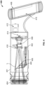
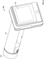
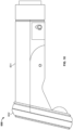
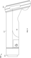
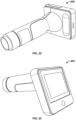
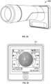
- FIG. 4 illustrates an embodiment of example fundus imaging system 400.
- the embodiment 400 includes a housing 401 that supports an optional fixation LED 402, an objective lens 404, fixation LED mirrors 405, variable focus lens assembly 406, display 408, printed circuit board 410, step motor 412, image sensor array 414, and illumination LED 416.
- light paths L that include potential light paths from optional fixation LED 402 and incoming light paths from outside the fundus imaging system 400.
- the illustrated components have the same or similar functionality to the corresponding components discussed above with reference to FIGs. 1-3 above. Other embodiments can include more or fewer components.
- the housing 401 of example fundus imaging system 400 is sized to be hand held.
- the housing 401 additionally supports one or more user input buttons near display 408, not shown in FIG. 4 .
- the user input button can initiate the image capture sequence, at least a portion of which is shown and discussed with reference to FIG. 3 , above.
- the fundus imaging system 400 is capable of being configured such that the clinician C does not need to adjust the lens focus.
- the embodiment of example fundus imaging system 400 also includes a variable focus lens assembly 406. As shown in FIG. 4 , the variable focus lens assembly 406 is substantially aligned with the longitudinal axis of the housing 401. Additionally, the variable focus lens assembly 406 is positioned between the objective lens 404 and the image sensor array 414 such that it can control the focus of the incident light L onto the image sensor array.
- Step motor 412 is an optional component in the example embodiment 400.
- Step motor 412 can also be, for example, a voice coil, an ultrasonic motor, or a piezoelectric actuator.
- step motor 412 moves the variable focus lens assembly 406 and/or the sensor array 414 to achieve variable focus.
- the step motor 412 moves the variable focus lens assembly 406 or the sensor array 414 in a direction parallel to a longitudinal axis of the housing 401 (the optical axis).
- the movement of step motor 412 is actuated by computing device 1800.
- the pupil or fovea or both of the patient P are monitored.
- the fundus imaging system 102 captures images in a first image capture mode. In the first image capture mode, the fundus imaging system 102 captures images at a higher frame rate. In some embodiments, in the first image capture mode, the fundus imaging system 102 captures images with infra-red illumination and at lower resolutions. In some embodiments, the infra-red illumination is created by the illumination LED 182 operating to generate and direct light of a lower intensity towards the subject.
- the first image capture mode may minimize discomfort to the patient P, allow the patient P to relax, and allow for a larger pupil size without dilation (non-mydriatic).
- the computing device 1800 processes at least a portion of the images captured by the fundus imaging system 102.
- the computing device 1800 processes the images to identify the location of the pupil or fovea or both of the patient P.
- a vector corresponding to the pupil/fovea orientation is calculated.
- the pupil/fovea orientation is approximated based on the distance between the pupil and fovea in the image.
- the pupil/fovea orientation is calculated by approximating the position of the fovea relative to the pupil in three dimensions using estimates of the distance to the pupil and the distance between the pupil and the fovea.
- the pupil/fovea orientation is approximated from the position of the pupil alone.
- other methods of approximating the pupil/fovea orientation are used.
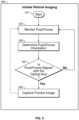
- the pupil/fovea orientation is compared to the optical axis of the fundus imaging system 102. If the pupil/fovea orientation is substantially aligned with the optical axis of the fundus imaging system 102, the process proceeds to step 309 to capture a fundus image. If not, the process returns to step 303 to continue to monitor the pupil or fovea. In some embodiments, the pupil/fovea orientation is substantially aligned with the optical axis when the angle between them is less than two to fifteen degrees.
- fundus images are captured by triggering the embodiment of example thru focusing image capturing method 200.
- five images are captured at step 309.
- the fundus image is captured in a second image capture mode.
- the fundus imaging system 102 captures images with visible illumination and at higher resolutions.
- the visible illumination is created by the illumination LED 182 operating to generate and direct light of a higher intensity towards the subject.
- the higher illumination is created by an external light source or ambient light.
- the second image capture mode may facilitate capturing a clear, well-illuminated, and detailed fundus image.
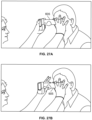
- the clinician positions the fundus imaging system near the patient's eye socket.
- the clinician positions the aperture of the system flush against the patient's eye socket such that the aperture, or a soft material eye cup extending from the aperture, seals out most of the ambient light.
- the example use 500 does not require positioning the aperture flush against the patient's eye socket.
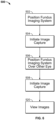
- the system captures more than one image of the fundus in operation 504.
- the system does not require the clinician to manually focus the lens. Additionally, the system does not attempt to autofocus on the fundus. Rather, the clinician simply initiates the image capture, via a button or the GUI, and the fundus imaging system controls when to capture the images and the focus of the variable focus lens. Also, as discussed above at least with reference to FIG. 5 , the system can initiate image capture using passive eye tracking.
- the patient may require the fundus imaging system to be moved away from the eye socket during image capture operation 504.
- the clinician can re-initiate the image capture sequence of the same eye using the button or the GUI on the display.
- the clinician then positions the fundus imaging system near or flush with the patient's other eye socket in operation 506. Again, when the system is in place, an image is captured in every zone in operation 508.
- the clinician can view the resulting images in operation 520.
- the images can be post-processed before the clinician views the images to select or synthesize a representative image.
- the fundus images can be sent to a remote location for viewing by a different medical professional.
- FIG. 7 is a block diagram illustrating physical components (i.e., hardware) of a computing device 1800 with which embodiments of the disclosure may be practiced.
- the computing device components described below may be suitable to act as the computing devices described above, such as wireless computing device and/or medical device of FIG. 1 .
- the computing device 1800 may include at least one processing unit 1802 and a system memory 1804.
- the system memory 1804 may comprise, but is not limited to, volatile storage (e.g., random access memory), non-volatile storage (e.g., read-only memory), flash memory, or any combination of such memories.
- the system memory 1804 may include an operating system 1805 and one or more program modules 1806 suitable for running software applications 1820.
- the operating system 1805 may be suitable for controlling the operation of the computing device 1800.
- embodiments of the disclosure may be practiced in conjunction with a graphics library, other operating systems, or any other application program and is not limited to any particular application or system.
- This basic configuration is illustrated in FIG. 7 by those components within a dashed line 1808.
- the computing device 1800 may have additional features or functionality.
- the computing device 1800 may also include additional data storage devices (removable and/or non-removable) such as, for example, magnetic disks, optical disks, or tape.
- additional storage is illustrated in FIG. 7 by a removable storage device 1809 and a non-removable storage device 1810.
- a number of program modules and data files may be stored in the system memory 1804. While executing on the at least one processing unit 1802, the program modules 1806 may perform processes including, but not limited to, generate list of devices, broadcast user-friendly name, broadcast transmitter power, determine proximity of wireless computing device, connect with wireless computing device, transfer vital sign data to a patient's EMR, sort list of wireless computing devices within range, and other processes described with reference to the figures as described herein.
- Other program modules that may be used in accordance with embodiments of the present disclosure, and in particular to generate screen content may include electronic mail and contacts applications, word processing applications, spreadsheet applications, database applications, slide presentation applications, drawing or computer-aided application programs, etc.
- embodiments of the disclosure may be practiced in an electrical circuit comprising discrete electronic elements, packaged or integrated electronic chips containing logic gates, a circuit utilizing a microprocessor, or on a single chip containing electronic elements or microprocessors.
- embodiments of the disclosure may be practiced via a system-on-a-chip (SOC) where each or many of the components illustrated in FIG. 7 may be integrated onto a single integrated circuit.
- SOC system-on-a-chip
- Such an SOC device may include one or more processing units, graphics units, communications units, system virtualization units and various application functionality all of which are integrated (or "burned") onto the chip substrate as a single integrated circuit.
- the computing device 1800 may also have one or more input device(s) 1812 such as a keyboard, a mouse, a pen, a sound or voice input device, a touch or swipe input device, etc.
- the output device(s) 1814 such as a display, speakers, a printer, etc. may also be included.
- the aforementioned devices are examples and others may be used.
- the computing device 1800 may include one or more communication connections 1816 allowing communications with other computing devices. Examples of suitable communication connections 1816 include, but are not limited to, RF transmitter, receiver, and/or transceiver circuitry; universal serial bus (USB), parallel, and/or serial ports.
- Embodiments of the present invention may be utilized in various distributed computing environments where tasks are performed by remote processing devices that are linked through a communications network in a distributed computing environment.
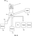
- the cloud system 704 can be used to provide a portal to allow for access to images by a device 708 of the clinician C and/or patient device 710 using a computing device such as a personal computing device, tablet, and/or mobile device. This can allow the images to be viewed, manipulated, etc.
- the cloud system 704 can be used to capture clinician C annotations and diagnoses.
- the cloud system 704 can be configured to interface with other third parties, such as insurance companies to allow for billing.
- the systems 600, 605 can be configured to operate in both manual and automatic modes when interfacing with the cloud system 704.
- the automatic mode includes one or more scripts that automate certain processes for the systems 600, 605. See FIG. 36 described below. These processes include automation of image focus and capture (acquisition) and output to the cloud for storage.
- the various processes can be manually controlled by the clinician C, such as focus on the fundus, capture of one or more images at desired times, and then uploading of the image(s) to the cloud. See FIG. 37 described below.
- a notification scheme is used for charging of the systems 600, 605.
- the systems 600, 605 are wireless and include a rechargeable battery pack, such as a lithium-ion battery or similar battery.
- a bi-color LED is used to indicate a status of charging of the battery pack when placed in a charging cradle 703. The LED is left off if charging is not occurring - this is the default state.
- the LED is illuminated a solid amber to indicate charging of the battery and a solid green when the battery charging is completed. If an error occurs during charging, the LED flashes an amber color.
- Other configurations are possible.
- the systems 600, 605 can be used to select a patient, adjust the eye cap, take an image, determine a quality of the image, and review the status of an image capture process.
- various other features such as adjustment of connectivity (e.g., WiFi) and cleaning of the device can be accomplished. Additional details on some of these processes are provided below.
- a physician (sometimes the same individual who captured the images or a different individual, such as an individual located at a remote location) can review the results of the image captures and develop/review a report based upon the same. See FIG. 45 described below.
- the systems 600, 605 can be used to transmit scheduling and/or image information to and from the cloud system 704.
- the EMR 706 is in communication with the cloud system 704 to transmit and store image and diagnoses information for each patient. Other configurations are possible.
- An over read service 712 is also shown in FIG. 33 .
- the over read service 712 can interact with the cloud system 704 to provide additional resources for analyzing the images, including reading of images and generating of reports.
- Other functions of the example system 700 include capture and forwarding of images to the cloud and communication between the cloud and the EMR 706 for storage thereof.
- the device 702 is used to capture one or more fundus images. After capture, the device 702 is returned to the charging cradle 703. Upon placement of the device 702 into the cradle 703, the captured images are automatically transferred to the cloud system 704. This transfer can be automated, so that no further action is required by the user to transfer the images from the device 702 to the cloud system 704.
- An example method for using the systems 600, 605 to capture fundus images includes preliminary tasks such as the capturing of patient vitals and education of the patient on the procedure are done. Once this is done, the system 600, 605 is powered on and the patient is selected on the device. The eye cup is then positioned on the patient and one or more images are captured using automated and/or manual processes. The images can then be checked. If accepted, the images are saved and/or uploaded to the cloud. The system 600, 605 can be powered off and returned to its cradle for charging. A physician can thereupon review the images, and the clinician C or patient can be notified of the results.
- An example method is provided to allow for capture of images even when the system 600, 605 loses connectivity with the cloud.
- automated quality checks may not be provided, and the clinician may be prompted as such. The clinician can then decide whether or not to accept the image without the quality check or to cancel the procedure.
- the system 600, 605 can be used to trouble shoot connectivity issues, as described further below.
- An example method for allowing the clinician to select the patient on the system 600, 605 includes a work list that is provided that identifies patients based upon one or more given criteria, such as the clinician, location, time of day, etc.
- the clinician is thereupon able to select the patient and confirms the proper patient has been selected, such as by comparing a code with one worn by the patient for from a picture of the patient.
- one or more images can be captured and stored. The captured images are associated with the selected patient.
- an example method allows the clinician to assure that the proper patient is selected.
- unique information is sent to the cloud, such as the system's serial number.
- The looks-up the serial number and returns a list of patients associated with that system.
- the clinician can thereupon select the patient from the list or manually enter the patient into the system 600, 605 if the patient is not on the work list.
- a user interface allows the user to pick between a selection of patients, examinations, review, and settings. If a patient is selected, the system 600, 605 proceeds with imaging of the fundus using an automated and/or manual process. Icons are used to represent different contexts on the user interfaces of the system 600, 605.
- An example method for adjusting certain settings of the system 600, 605 includes, for example, brightness and focus, which can be selected automatically or manually manipulated by the clinician.
- An example method for manually acquiring an image is similar to the method described above, except the acquisition of the images is done manually by the clinician. This is accomplished by the clinician manually indicating when an image is to be taken. Upon capture, the image can be verified manually or automatically.
- An example method for selecting a patient from a worklist starts upon selection of the patient icon from the interface for the system 600, 605.
- a list of patients is presented to the clinician in the worklist.
- the clinician can select a patient from the list to be presented with additional information about that patient, such as full name, date of birth, and patient ID. If any unsaved images exist, those images are associated with the selected patient. If not, a new examination routine is executed to allow for capture of images to be associated with the selected patient.
- the clinician is first prompted to save or discard the images before returning to the home screen.
- the method includes displaying a prompt with a save button to allow the clinician to save the images. Once saved, the home screen is displayed.
- the system 600, 605 is placed in a charging cradle.
- an icon indicating a USB connection is displayed on the dock and/or the system 600, 605. If acquisition is complete, the screen is turned off and sleep is instituted without a certain time period (e.g., one minute). If acquisition is not complete, the clinician is prompted to complete acquisition.
- software can be uploaded from a removable storage medium (e.g., SD card) during boot to update the software on the system 600, 605.
- software can be downloaded, such as from the cloud.
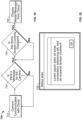
- the system 700 allows for messaging to the clinician who is capturing the fundus images.
- the cloud system 704 and/or the clinicians working as part of the over read service 712 can directly message the clinician capturing the fundus images regarding such as issues as image quality.
- the message 729 can be displayed so as to get the attention of the clinician operating the device 702, such as by popping up, color, sound, etc.
- the message 729 can provide information regarding the quality of the images that have been captured by the device 702. For example, if the images are not of a sufficient quality for the over read service 712, the over read service 712 can send a message to the device 702.
- the clinician C can read the message, as well as information about how to remedy the situation (e.g., the message could provide information such as "Clean a certain part of the lens, etc.).
- the cloud system 704 can be used to store various information associated with the examination of a given patient. For example, as the fundus images are captured, the clinician C can adjust various settings associated with the device 702, such as brightness, focus, etc. Once a desired set of settings is identified for a particular patient, these settings can be stored in the cloud system 704 (e.g., in a database) and/or the EMR 706 and associated with the patient. When the patient returns for a subsequent examination, the device 702 can be configured to automatically access the settings for the device 702 by downloading the settings from the cloud system 704. In this manner, the device 702 can be automatically configured according to those settings for subsequent capture of the patient's fundus images.
- the cloud system 704 can be used to store various information associated with the examination of a given patient. For example, as the fundus images are captured, the clinician C can adjust various settings associated with the device 702, such as brightness, focus, etc. Once a desired set of settings is identified for a particular patient, these settings can be stored in the cloud system 704 (e
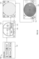
- the clinician C is presented with a menu of options, including an examination icon.
- the clinician C selects the examination icon to initiate the workflow 730.
- the clinician C is presented by the device 702 with options to start the workflow 730 or to perform a manual capture of fundus images (see FIG. 37 ).
- the clinician C selects the "Start" button 735 to begin the workflow 730 (or can select the manual capture icon 737 to manually capture images as described further below.
- the device 702 automatically captures the desired fundus images from the patient P.
- the image capture can include one or more tones indicating the capture of images, along with automated quality checks on the images.
- An example of such a process for automating the capture of fundus images is described in U.S. Patent Application Serial No. 15/009988 .
- the clinician C can review the captured images.
- the clinician C can perform such actions as discarding images and/or adding images, as described further below.
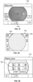
- the clinician C can decide to discard one or more of the fundus images.
- the clinician C is provided with various options. If one option is selected (e.g., a "Close" icon 742), the device 702 returns to the pre-acquisition stage 734. If another option is selected (e.g., a trash icon 744), the device 702 returns to the acquisition stage 736 to allow for the immediate retake of the fundus image(s). Other configurations are possible.
- clinician C can add images for the patient P.
- a user interface includes a control 748 that allows the clinician C to add images by returning the device 702 to the pre-acquisition stage 734. At that point, the device 702 can be used to capture further fundus images that are associated with the patient P.
- the workflow for the device 702 is defined by one or more scripts.
- the scripts can be downloaded from the cloud system 704 to allow for the modification of the functionality of the device 702.
- a particular script can be selected by the clinician C to modify the workflow for the device 702.
- the device 702 can be programmed to automatically select a script based upon such parameters as clinician C preference, over read service, etc.
Landscapes
- Health & Medical Sciences (AREA)
- Life Sciences & Earth Sciences (AREA)
- Engineering & Computer Science (AREA)
- General Health & Medical Sciences (AREA)
- Surgery (AREA)
- Biophysics (AREA)
- Biomedical Technology (AREA)
- Heart & Thoracic Surgery (AREA)
- Medical Informatics (AREA)
- Molecular Biology (AREA)
- Veterinary Medicine (AREA)
- Animal Behavior & Ethology (AREA)
- Physics & Mathematics (AREA)
- Public Health (AREA)
- Ophthalmology & Optometry (AREA)
- Signal Processing (AREA)
- Eye Examination Apparatus (AREA)
- Computer Networks & Wireless Communication (AREA)
- Pathology (AREA)
Claims (11)
- System zum Aufzeichnen und Anzeigen eines Bild seines Fundus eines Patienten, wobei das System eine Vorrichtung (100, 400, 600, 605, 702) zum Herstellen eines Fundusbilds und einen Dienst zur erneuten Überprüfung (712) umfasst, wobei die Vorrichtung (100, 400, 600, 605, 702) Folgendes umfasst:einen Prozessor (1800) und einen Speicher (1804);eine Beleuchtungskomponente, die eine Lichtquelle beinhaltet und funktionell mit dem Prozessor (1800) gekoppelt ist);eine Anzeige (108); undeine Kamera (104), die zum Aufzeichnen von Bildern eines Fundus konfiguriert ist, wobei die Kamera ein Objektiv (180, 404, 406) aufweist und funktionell mit dem Prozessor (1800) gekoppelt ist,wobei der Speicher (1804) Anweisungen speichert, die bei Ausführung durch den Prozessor (1800) die Vorrichtung (100, 400, 600, 605, 702) veranlassen zum:Bereitstellen einer Benutzeroberfläche auf der Anzeige (108), die Optionen für einen Benutzer zum Auswählen einer Augenstellung und eines Fixationsziels, bevor ein Fundusbild aufgenommen wird, und Optionen für einen Benutzer zum Durchführen der automatischen Erfassung eines Fundusbilds oder der manuellen Erfassung eines Fundusbilds;Definieren spezifischer Bilder eines Fundus eines Patienten zur Erfassung bei Auswahl einer Augenstellung und eines Fixationsziels durch einen Benutzer;automatisches oder manuelles Erfassen der spezifischen Bilder des Fundus des Patienten in Abhängigkeit von der Auswahl eines Benutzer auf der Benutzeroberfläche, wobei das Erfassen Folgendes aufweist:Ausführung eines automatisierten Skripts zur Erfassung des Fundusbilds bei Auswahl der Option zum Durchführen der automatischen Erfassung eines Fundusbilds;Ausführung von Anweisungen, die einem Benutzer das Überschreiben des automatisierten Skripts zur Erfassung des Fundusbilds ermöglichen, um das Fundusbild manuell zu erfassen, bei Auswahl der Option zum Durchführen der manuellen Erfassung eines Fundusbilds, wobei die Anweisungen zum manuellen Erfassen des Fundusbilds Folgendes aufweisen:Bereitstellen von einer oder mehreren Führungen zum Unterstützen des Benutzers bei der Positionierung der Vorrichtung relativ zum Auge eines Patienten; undautomatisches Auslösen der Erfassung des Fundusbilds, wenn der Benutzer die Vorrichtung in Position bewegt;automatisches Senden von einem oder mehreren der spezifischen Bilder des Fundus des Patienten zu dem Dienst zur erneuten Überprüfung (712), um Rückinformationen direkt von einem oder mehreren Klinikern, die als Teil des Dienstes zur erneuten Überprüfung (712) bezüglich des Fundusbilds arbeiten zu erhalten,Empfangen von Rückinformationen von dem einen oder den mehreren Klinikern, die als Teil des Dienstes zur erneuten Überprüfung (712) arbeiten, über eine Qualität des einen oder der mehreren spezifischen Bilder des Fundus; undDarstellen einer Nachricht auf der Anzeige, die die Rückinformationen über die Qualität des Fundusbilds von dem Dienst zur erneuten Überprüfung (712) aufweist.
- System nach Anspruch 1, wobei der Prozessor (1800) weitere Anweisungen ausführt, die die Vorrichtung (100, 400, 600, 605, 702) zum automatischen Senden des Fundusbilds an eine ferne Rechenvorrichtung zur Speicherung veranlassen.
- System nach Anspruch 1, wobei der Prozessor (1800) weitere Anweisungen ausführt, die die Vorrichtung (100, 400, 600, 605, 702) zum Anzeigen von einer oder mehreren Nachrichten von einer fernen Rechenvorrichtung veranlassen.
- System nach Anspruch 1, ferner umfassend eine Mehrzahl von Skripts, die die automatisierte Erfassung des Fundusbilds ermöglichen.
- System nach Anspruch 4, wobei der Prozessor (1800) weitere Anweisungen ausführt, die die Vorrichtung (100, 400, 600, 605, 702) veranlassen, einem Benutzer das Übersteuern der Mehrzahl von Skripts zu ermöglichen, um das Fundusbild manuell zu erfassen.
- System nach Anspruch 1, wobei der Prozessor (1800) weitere Anweisungen ausführt, die die Vorrichtung (100, 400, 600, 605, 702) zum automatischen Angeben einer Qualität des Fundusbilds veranlassen.
- Verfahren zur Erfassung von einem oder mehreren Bildern eines Fundus eines Patienten, wobei das Verfahren Folgendes umfasst:Bereitstellen einer Benutzeroberfläche auf einer Anzeige (108), wobei die Benutzeroberfläche Optionen für einen Benutzer zum Auswählen einer Augenstellung und eines Fixationsziels vor dem Aufnehmen eines Fundusbilds und Optionen für einen Benutzer zum Durchführen einer automatischen Erfassung eines Fundusbilds oder manuellen Erfassung eines Fundusbilds aufweist;Definieren spezifischer Bilder eines Fundus eines Patienten zur Erfassung, bei Auswahl durch einen Benutzer, einer Augenstellung und eines Fixationsziels;automatisches oder manuelles Erfassen von einem oder mehreren der spezifischen Bilder des Fundus in Abhängigkeit von der Auswahl eines Benutzer auf der Benutzeroberfläche, wobei das Erfassen eine Vorrichtung (100, 400, 600, 605, 702) verwendet, die eine Kamera (104) umfasst, die zum Aufzeichnen von Bildern eines Fundus konfiguriert ist, und Folgendes aufweist:Ausführen eines automatisierten Skripts zur Erfassung des Fundusbilds bei Auswahl der Option zum Durchführen der automatischen Erfassung eines Fundusbilds;Ausführen von Anweisungen, die einem Benutzer das Übersteuern des automatisierten Skripts zur Erfassung des Fundusbilds ermöglichen, um das Fundusbild manuell zu erfassen, bei Auswahl der Option zum Durchführen der manuellen Erfassung eines Fundusbilds, wobei die Anweisungen zum manuellen Erfassen des Fundusbilds Folgendes aufweisen:Bereitstellen von einer oder mehreren Führungen zum Unterstützen des Benutzers bei der Positionierung der Vorrichtung relativ zum Auge eines Patienten; undautomatisches Auslösen der Erfassung des Fundusbilds, wenn der Benutzer die Vorrichtung in Position bewegt;automatisches Senden des einen oder der mehreren spezifischen Bilder des Fundus zu einem Dienst zur erneuten Überprüfung (712), um Rückinformationen direkt von einem oder mehreren Klinikern, die als Teil des Dienstes zur erneuten Überprüfung (712) arbeiten, bezüglich des Fundusbilds zu erhalten;Empfangen von Rückinformationen von dem einen oder den mehreren Klinikern, die als Teil des Dienstes zur erneuten Überprüfung (712) arbeiten, über eine Qualität des einen oder der mehreren spezifischen Bilder des Fundus; undDarstellen einer Nachricht auf der Anzeige, die die Rückinformationen über die Qualität des Fundusbilds von dem Dienst zur erneuten Überprüfung (712) aufweist.
- Verfahren nach Anspruch 7, ferner umfassend das Auswählen aus einer Mehrzahl von Skripts, die die automatisierte Erfassung des einen oder der mehreren Bilder des Findus ermöglichen.
- Verfahren nach Anspruch 8, ferner umfassend:automatisches Definieren, durch das Ausführen von einem der Mehrzahl von Skripts durch die Vorrichtung (100, 400, 600, 605, 702), spezifischer Bilder eines Fundus eines Patienten zur Erfassung;automatisches Erfassen, durch das Ausführen von einem der Mehrzahl von Skripts durch die Vorrichtung (100, 400, 600, 605, 702), der spezifischen Bilder des Fundus des Patienten; undautomatisches Analysieren, durch das Ausführen von einem der Mehrzahl von Skripts durch die Vorrichtung (100, 400, 600, 605, 702), der Qualität von jedem der spezifischen Bilder des Fundus des Patienten.
- Verfahren nach Anspruch 7, das ferner das automatische Angeben der Qualität des einen oder der mehreren Bilder des Fundus umfasst.
- Verfahren nach Anspruch 7, ferner umfassend das automatische Analysieren des einen oder der mehreren Bilder des Fundus durch eine Vorrichtung (100, 400, 600, 605, 702); und Darstellen der Ergebnisse des Analysierens auf der Vorrichtung (100, 400, 600, 605, 702); wobei die Ergebnisse zumindest einen Eintrag für jedes von dem einen oder den mehreren Bildern des Fundus aufweisen, wobei der mindestens eine Eintrag eine Beschreibung des einen oder der mehreren Bilder und eine Qualitätsangabe für das eine oder die mehreren Bilder aufweist.
Applications Claiming Priority (3)
| Application Number | Priority Date | Filing Date | Title |
|---|---|---|---|
| US201562249931P | 2015-11-02 | 2015-11-02 | |
| US15/054,558 US10772495B2 (en) | 2015-11-02 | 2016-02-26 | Retinal image capturing |
| PCT/US2016/059150 WO2017079034A1 (en) | 2015-11-02 | 2016-10-27 | Retinal image capturing |
Publications (3)
| Publication Number | Publication Date |
|---|---|
| EP3370596A1 EP3370596A1 (de) | 2018-09-12 |
| EP3370596A4 EP3370596A4 (de) | 2019-06-12 |
| EP3370596B1 true EP3370596B1 (de) | 2025-07-02 |
Family
ID=58638096
Family Applications (1)
| Application Number | Title | Priority Date | Filing Date |
|---|---|---|---|
| EP16862740.4A Active EP3370596B1 (de) | 2015-11-02 | 2016-10-27 | Netzhautbilderfassung |
Country Status (5)
| Country | Link |
|---|---|
| US (4) | US10772495B2 (de) |
| EP (1) | EP3370596B1 (de) |
| CN (1) | CN108430307B (de) |
| AU (1) | AU2016350626B2 (de) |
| WO (1) | WO2017079034A1 (de) |
Families Citing this family (20)
| Publication number | Priority date | Publication date | Assignee | Title |
|---|---|---|---|---|
| US9211064B2 (en) | 2014-02-11 | 2015-12-15 | Welch Allyn, Inc. | Fundus imaging system |
| US9237847B2 (en) | 2014-02-11 | 2016-01-19 | Welch Allyn, Inc. | Ophthalmoscope device |
| US10799115B2 (en) | 2015-02-27 | 2020-10-13 | Welch Allyn, Inc. | Through focus retinal image capturing |
| US11045088B2 (en) | 2015-02-27 | 2021-06-29 | Welch Allyn, Inc. | Through focus retinal image capturing |
| US10136804B2 (en) | 2015-07-24 | 2018-11-27 | Welch Allyn, Inc. | Automatic fundus image capture system |
| US10772495B2 (en) | 2015-11-02 | 2020-09-15 | Welch Allyn, Inc. | Retinal image capturing |
| US10413179B2 (en) | 2016-01-07 | 2019-09-17 | Welch Allyn, Inc. | Infrared fundus imaging system |
| US10602926B2 (en) | 2016-09-29 | 2020-03-31 | Welch Allyn, Inc. | Through focus retinal image capturing |
| USD881938S1 (en) | 2017-05-18 | 2020-04-21 | Welch Allyn, Inc. | Electronic display screen of a medical device with an icon |
| WO2018213471A1 (en) | 2017-05-18 | 2018-11-22 | Farchione Richard M | Fundus image capturing |
| US11096574B2 (en) * | 2018-05-24 | 2021-08-24 | Welch Allyn, Inc. | Retinal image capturing |
| US10993613B2 (en) * | 2018-12-21 | 2021-05-04 | Welch Allyn, Inc. | Fundus image capturing |
| US11138732B2 (en) * | 2018-12-21 | 2021-10-05 | Welch Allyn, Inc. | Assessment of fundus images |
| US11283975B2 (en) | 2018-12-21 | 2022-03-22 | Welch Allyn, Inc. | Eye image capturing |
| USD921899S1 (en) * | 2019-06-07 | 2021-06-08 | Welch Allyn, Inc. | Scanner |
| US11915826B2 (en) * | 2019-06-07 | 2024-02-27 | Welch Allyn, Inc. | Digital image screening and/or diagnosis using artificial intelligence |
| WO2021133464A1 (en) | 2019-12-26 | 2021-07-01 | Verily Life Sciences Llc | Eye cup for passive feedback for fundus camera alignment |
| US11950848B2 (en) * | 2020-08-10 | 2024-04-09 | Welch Allyn, Inc. | Fundus imaging for microvascular assessment |
| EP4199801A1 (de) | 2020-08-19 | 2023-06-28 | Phelcom Technologies S/A | System, vorrichtung und verfahren zur tragbaren, verbundenen und intelligenten augenabbildung |
| US11375891B1 (en) | 2021-12-17 | 2022-07-05 | The Trustees Of Indiana University | Methods, systems, and devices for vision testing |
Family Cites Families (220)
| Publication number | Priority date | Publication date | Assignee | Title |
|---|---|---|---|---|
| US5048946A (en) | 1990-05-15 | 1991-09-17 | Phoenix Laser Systems, Inc. | Spectral division of reflected light in complex optical diagnostic and therapeutic systems |
| US6198532B1 (en) | 1991-02-22 | 2001-03-06 | Applied Spectral Imaging Ltd. | Spectral bio-imaging of the eye |
| US5713047A (en) | 1992-06-08 | 1998-01-27 | Canon Kabushiki Kaisha | Eye fundus photographing apparatus |
| DE4334823C2 (de) | 1993-10-09 | 1998-09-17 | Schering Ag | Verfahren zur Herstellung von Schwefelsäurehalbestern von Estrogenen |
| JP3441159B2 (ja) | 1994-04-15 | 2003-08-25 | 株式会社ニデック | 眼科装置 |
| US5703621A (en) | 1994-04-28 | 1997-12-30 | Xerox Corporation | Universal display that presents all image types with high image fidelity |
| US6011585A (en) * | 1996-01-19 | 2000-01-04 | Apple Computer, Inc. | Apparatus and method for rotating the display orientation of a captured image |
| US5599276A (en) | 1996-02-13 | 1997-02-04 | Welch Allyn, Inc. | Diopter value viewing means for a video ophthalmoscope |
| US5784148A (en) | 1996-04-09 | 1998-07-21 | Heacock; Gregory Lee | Wide field of view scanning laser ophthalmoscope |
| US6089716A (en) | 1996-07-29 | 2000-07-18 | Lashkari; Kameran | Electro-optic binocular indirect ophthalmoscope for stereoscopic observation of retina |
| US5776060A (en) | 1997-02-20 | 1998-07-07 | University Of Alabama In Huntsville | Method and apparatus for measuring blood oxygen saturation within a retinal vessel with light having several selected wavelengths |
| IL132123A0 (en) * | 1997-04-01 | 2001-03-19 | Univ Johns Hopkins | A system for imaging an ocular fundus semi-automatically at high resolution and wide field |
| CA2233047C (en) | 1998-02-02 | 2000-09-26 | Steve Mann | Wearable camera system with viewfinder means |
| US6000799A (en) | 1998-05-01 | 1999-12-14 | Jozef F. Van De Velde | Maxwellian view and modulation control options for the scanning laser ophthalmoscope |
| US6637882B1 (en) | 1998-11-24 | 2003-10-28 | Welch Allyn, Inc. | Eye viewing device for retinal viewing through undilated pupil |
| US7419467B2 (en) | 1998-11-25 | 2008-09-02 | M3 Electronics, Inc. | Medical inspection device |
| JP4119027B2 (ja) | 1999-01-28 | 2008-07-16 | 興和株式会社 | 眼科撮影装置 |
| US6120461A (en) | 1999-08-09 | 2000-09-19 | The United States Of America As Represented By The Secretary Of The Army | Apparatus for tracking the human eye with a retinal scanning display, and method thereof |
| US6301440B1 (en) * | 2000-04-13 | 2001-10-09 | International Business Machines Corp. | System and method for automatically setting image acquisition controls |
| US6494878B1 (en) | 2000-05-12 | 2002-12-17 | Ceramoptec Industries, Inc. | System and method for accurate optical treatment of an eye's fundus |
| US20030163031A1 (en) | 2000-06-26 | 2003-08-28 | Adlabs, Inc. | Method and system for providing centralized anatomic pathology services |
| US6296358B1 (en) | 2000-07-14 | 2001-10-02 | Visual Pathways, Inc. | Ocular fundus auto imager |
| AU2001288372A1 (en) * | 2000-08-23 | 2002-03-04 | Philadelphia Ophthalmologic Imaging Systems, Inc. | System and method for tele-ophthalmology |
| US6309070B1 (en) | 2000-09-06 | 2001-10-30 | Medibell Medical Vision Technologies, Ltd. | Integrated ophthalmic illumination method and system |
| DE10103922A1 (de) | 2001-01-30 | 2002-08-01 | Physoptics Opto Electronic Gmb | Interaktives Datensicht- und Bediensystem |
| GB2378600A (en) | 2001-08-06 | 2003-02-12 | Patrick Kerr | Retinal function camera to determine retinal blood oxygenation. |
| GB2375679A (en) | 2001-04-09 | 2002-11-20 | Patrick Kerr | Retinal function camera using plural light wavelengths to produce a retinal function image showing haemoglobin oxygenation. |
| AU2002307381A1 (en) | 2001-04-16 | 2002-10-28 | Tracey Technologies, Llc | Determining clinical refraction of eye |
| EP1444635B1 (de) | 2001-10-03 | 2017-05-10 | Retinalyze A/S | Wundenbewertung in einem bild |
| DE10151314A1 (de) * | 2001-10-17 | 2003-04-30 | Zeiss Carl Jena Gmbh | Ophthalmologisches Untersuchungsgerät |
| US6666857B2 (en) | 2002-01-29 | 2003-12-23 | Robert F. Smith | Integrated wavefront-directed topography-controlled photoablation |
| AUPS158302A0 (en) | 2002-04-09 | 2002-05-16 | Scan Optics Pty Ltd | Improved fundus camera |
| US6758564B2 (en) | 2002-06-14 | 2004-07-06 | Physical Sciences, Inc. | Line-scan laser ophthalmoscope |
| US7404640B2 (en) | 2002-06-14 | 2008-07-29 | Physical Sciences, Inc. | Monitoring blood flow in the retina using a line-scanning laser ophthalmoscope |
| DE50212076D1 (de) | 2002-12-16 | 2008-05-21 | Sis Ag Surgical Instr Systems | Opthalmologische Vorrichtung und opthalmologisches Messverfahren |
| US7380938B2 (en) | 2003-03-25 | 2008-06-03 | Sarnoff Corporation | Apparatus to detect and measure saccade and pupilary changes |
| US7467869B2 (en) | 2003-04-11 | 2008-12-23 | Bausch & Lomb Incorporated | System and method for acquiring data and aligning and tracking of an eye |
| WO2005006943A2 (en) | 2003-07-03 | 2005-01-27 | Medibell Medical Vision Technologies, Ltd. | An illumination method and system for obtaining color images by transcleral ophthalmic illumination |
| WO2005044098A1 (en) | 2003-10-28 | 2005-05-19 | Welch Allyn, Inc. | Digital documenting ophthalmoscope |
| EP1691670B1 (de) | 2003-11-14 | 2014-07-16 | Queen's University At Kingston | Verfahren und gerät für die kalibrationsfreie augenverfolgung |
| US20070174152A1 (en) | 2003-12-08 | 2007-07-26 | Bjornberg David B | Handheld system for information acquisition, verification, recording, processing, display and communication |
| CA2561287C (en) | 2004-04-01 | 2017-07-11 | William C. Torch | Biosensors, communicators, and controllers monitoring eye movement and methods for using them |
| CN100349542C (zh) | 2004-05-29 | 2007-11-21 | 倪蔚民 | 实时自动无侵害的虹膜光学成像装置 |
| GB2415778B (en) | 2004-06-29 | 2008-05-14 | Patrick Kerr | Analysis of retinal metabolism over at least a portion of a cardiac cycle |
| WO2006016366A2 (en) | 2004-08-12 | 2006-02-16 | Elop Electro-Optical Industries Ltd. | Integrated retinal imager and method |
| US7377643B1 (en) | 2004-08-13 | 2008-05-27 | Q Step Technologies, Inc. | Method and apparatus for eye imaging with position registration and constant pupil size |
| JP4627169B2 (ja) | 2004-09-30 | 2011-02-09 | 株式会社ニデック | 眼底カメラ |
| US7234641B2 (en) | 2004-12-01 | 2007-06-26 | Datalogic Scanning, Inc. | Illumination pulsing method for a data reader |
| US7301644B2 (en) * | 2004-12-02 | 2007-11-27 | University Of Miami | Enhanced optical coherence tomography for anatomical mapping |
| US20060147095A1 (en) | 2005-01-03 | 2006-07-06 | Usher David B | Method and system for automatically capturing an image of a retina |
| WO2006078928A2 (en) * | 2005-01-18 | 2006-07-27 | Trestle Corporation | System and method for creating variable quality images of a slide |
| US7611060B2 (en) | 2005-03-11 | 2009-11-03 | Hand Held Products, Inc. | System and method to automatically focus an image reader |
| US7568628B2 (en) | 2005-03-11 | 2009-08-04 | Hand Held Products, Inc. | Bar code reading device with global electronic shutter control |
| JP4843242B2 (ja) | 2005-03-31 | 2011-12-21 | 株式会社トプコン | 眼底カメラ |
| US8388523B2 (en) | 2005-04-01 | 2013-03-05 | Welch Allyn, Inc. | Medical diagnostic instrument having portable illuminator |
| DE202005007013U1 (de) | 2005-05-02 | 2005-10-13 | Heine Optotechnik Gmbh & Co Kg | Ophthalmoskop |
| US7770799B2 (en) | 2005-06-03 | 2010-08-10 | Hand Held Products, Inc. | Optical reader having reduced specular reflection read failures |
| DE102005034332A1 (de) | 2005-07-22 | 2007-01-25 | Carl Zeiss Meditec Ag | Einrichtung und Verfahren zur Beobachtung, Dokumentation und/oder Diagnose des Augenhintergrundes |
| US7458685B2 (en) | 2005-08-03 | 2008-12-02 | Carestream Health, Inc. | Automated fundus imaging system |
| JP4819478B2 (ja) | 2005-10-31 | 2011-11-24 | 株式会社ニデック | 眼科撮影装置 |
| JP4855085B2 (ja) | 2006-01-27 | 2012-01-18 | 興和株式会社 | 視野計 |
| DE102006010105A1 (de) | 2006-02-28 | 2007-08-30 | Carl Zeiss Meditec Ag | Ophthalmologisches Gerät |
| US8488895B2 (en) | 2006-05-31 | 2013-07-16 | Indiana University Research And Technology Corp. | Laser scanning digital camera with pupil periphery illumination and potential for multiply scattered light imaging |
| US7470024B2 (en) | 2006-06-12 | 2008-12-30 | Opto Eletronics S/A | System for obtaining a fundus image |
| DE502006005346D1 (de) | 2006-07-07 | 2009-12-24 | Od Os Gmbh | Ophthalmoskop |
| US7802884B2 (en) * | 2006-09-28 | 2010-09-28 | University Of Rochester | Compact ocular fundus camera |
| US7976162B2 (en) | 2006-09-29 | 2011-07-12 | Daniel Ian Flitcroft | Eye examining system and method |
| JP5085086B2 (ja) | 2006-10-04 | 2012-11-28 | 株式会社トプコン | 眼底観察装置、眼底画像表示装置及びプログラム |
| US7769219B2 (en) | 2006-12-11 | 2010-08-03 | Cytyc Corporation | Method for assessing image focus quality |
| DE102006061933A1 (de) | 2006-12-21 | 2008-06-26 | Carl Zeiss Meditec Ag | Optisches System für eine Funduskamera |
| US7621636B2 (en) | 2007-01-10 | 2009-11-24 | Clarity Medical Systems, Inc. | Working distance and alignment sensor for a fundus camera |
| WO2008106802A1 (en) | 2007-03-08 | 2008-09-12 | University Of Northern British Columbia | Apparatus and method for objective perimetry visual field test |
| JP4971863B2 (ja) | 2007-04-18 | 2012-07-11 | 株式会社トプコン | 光画像計測装置 |
| JP4971872B2 (ja) | 2007-05-23 | 2012-07-11 | 株式会社トプコン | 眼底観察装置及びそれを制御するプログラム |
| JP2008295971A (ja) | 2007-06-04 | 2008-12-11 | Nidek Co Ltd | 眼底カメラ |
| IL184399A0 (en) | 2007-07-03 | 2007-10-31 | Yossi Tsuria | Content delivery system |
| GB2457867B (en) | 2007-10-08 | 2010-11-03 | Keymed | Electronic camera |
| JP5080998B2 (ja) | 2008-01-24 | 2012-11-21 | 株式会社トプコン | 眼科撮影装置 |
| DE102008000225B3 (de) | 2008-02-01 | 2009-03-26 | Linos Photonics Gmbh & Co. Kg | Fundusabtastvorrichtung |
| WO2009109975A2 (en) | 2008-03-05 | 2009-09-11 | Tamir Gil | Snapshot spectral imaging of the eye |
| JP5101354B2 (ja) | 2008-03-14 | 2012-12-19 | 株式会社ニデック | 走査型眼底撮影装置 |
| WO2010009447A2 (en) | 2008-07-18 | 2010-01-21 | Doheny Eye Institute | Optical coherence tomography - based ophthalmic testing methods, devices and systems |
| US8348429B2 (en) | 2008-03-27 | 2013-01-08 | Doheny Eye Institute | Optical coherence tomography device, method, and system |
| JP5143772B2 (ja) | 2008-03-28 | 2013-02-13 | パナソニック株式会社 | 画像表示装置および画像表示方法 |
| US20110028513A1 (en) | 2008-03-31 | 2011-02-03 | Lang Zhuo | Method for treating neurological disorders with imidazolium and imidazolinium compounds |
| EP2278909B1 (de) | 2008-04-22 | 2016-02-17 | Annidis Health Systems Corp. | Verfahren und gerät zur beobachtung des netzhauthintergrunds |
| US8807751B2 (en) | 2008-04-22 | 2014-08-19 | Annidis Health Systems Corp. | Retinal fundus surveillance method and apparatus |
| ES2327704B1 (es) | 2008-04-30 | 2010-08-30 | Universitat Politecnica De Catalunya | Metodo y sistema para la medida objetiva de la acomodacion ocular. |
| WO2009135084A1 (en) | 2008-04-30 | 2009-11-05 | Amo Development, Llc | System and method for controlling measurement in an eye during ophthalmic procedure |
| JP5268447B2 (ja) | 2008-06-26 | 2013-08-21 | キヤノン株式会社 | 医療用撮影装置 |
| JP5255524B2 (ja) | 2008-07-04 | 2013-08-07 | 株式会社ニデック | 光断層像撮影装置、光断層像処理装置。 |
| JP5159526B2 (ja) | 2008-09-01 | 2013-03-06 | キヤノン株式会社 | 眼底カメラ |
| JP5558688B2 (ja) | 2008-09-25 | 2014-07-23 | キヤノン株式会社 | 眼科装置および画像生成方法 |
| JP5607640B2 (ja) | 2008-10-15 | 2014-10-15 | オプティブランド リミティド,リミティド ライアビリティ カンパニー | 眼の特徴の画像を得る方法と装置 |
| US7854510B2 (en) * | 2008-10-16 | 2010-12-21 | Steven Roger Verdooner | Apparatus and method for imaging the eye |
| US20110261184A1 (en) * | 2008-10-17 | 2011-10-27 | Mason Michael S | Optical microscope methods and apparatuses |
| US20100245765A1 (en) | 2008-10-28 | 2010-09-30 | Dyer Holdings, Llc | Video infrared ophthalmoscope |
| WO2010071898A2 (en) * | 2008-12-19 | 2010-06-24 | The Johns Hopkins Univeristy | A system and method for automated detection of age related macular degeneration and other retinal abnormalities |
| CA3060821C (en) | 2008-12-19 | 2023-09-12 | University Of Miami | System and method for early detection of diabetic retinopathy using optical coherence tomography |
| JP5364385B2 (ja) | 2009-01-06 | 2013-12-11 | 株式会社トプコン | 光画像計測装置及びその制御方法 |
| JP5213772B2 (ja) | 2009-03-19 | 2013-06-19 | キヤノン株式会社 | 眼底カメラ |
| WO2010115195A1 (en) | 2009-04-03 | 2010-10-07 | Dyer Holdings, Llc | Infrared slit lamp ophthalmoscope |
| JP2010259492A (ja) | 2009-04-30 | 2010-11-18 | Topcon Corp | 眼底観察装置 |
| US8240853B2 (en) | 2009-05-01 | 2012-08-14 | Bioptigen, Inc. | Systems for imaging structures of a subject and related methods |
| JP5317830B2 (ja) | 2009-05-22 | 2013-10-16 | キヤノン株式会社 | 眼底観察装置 |
| WO2010138645A2 (en) | 2009-05-29 | 2010-12-02 | University Of Pittsburgh - Of The Commonwealth System Of Higher Education | Blood vessel segmentation with three-dimensional spectral domain optical coherence tomography |
| CN101658412A (zh) * | 2009-06-19 | 2010-03-03 | 中卫莱康科技发展(北京)有限公司 | 移动通信装置、远程医疗系统及移动通信装置的控制方法 |
| JP5432625B2 (ja) | 2009-07-29 | 2014-03-05 | 株式会社トプコン | 眼科観察装置 |
| US7862173B1 (en) | 2009-07-29 | 2011-01-04 | VistaMed, LLC | Digital imaging ophthalmoscope |
| JP5021007B2 (ja) | 2009-08-27 | 2012-09-05 | キヤノン株式会社 | 眼科撮影装置及び該眼科撮影装置に用いるカメラ |
| US20130057828A1 (en) | 2009-08-31 | 2013-03-07 | Marc De Smet | Handheld portable fundus imaging system and method |
| US9357920B2 (en) * | 2009-09-04 | 2016-06-07 | University Of Virginia Patent Foundation | Hand-held portable fundus camera for screening photography |
| GB2474083B (en) | 2009-10-05 | 2015-12-23 | Keeler Ltd | Improvements in and relating to ophthalmic instruments |
| WO2011047214A2 (en) | 2009-10-14 | 2011-04-21 | Optimum Technologies, Inc. | Portable retinal camera and image acquisition method |
| JP5697325B2 (ja) | 2009-11-04 | 2015-04-08 | キヤノン株式会社 | 眼底観察装置、眼底観察方法及びコンピュータプログラム |
| WO2011069137A1 (en) | 2009-12-04 | 2011-06-09 | Lumetrics, Inc. | Portable fundus camera |
| US8696122B2 (en) | 2010-01-21 | 2014-04-15 | Physical Sciences, Inc. | Multi-functional adaptive optics retinal imaging |
| US8649008B2 (en) | 2010-02-04 | 2014-02-11 | University Of Southern California | Combined spectral and polarimetry imaging and diagnostics |
| US8467133B2 (en) | 2010-02-28 | 2013-06-18 | Osterhout Group, Inc. | See-through display with an optical assembly including a wedge-shaped illumination system |
| JP5631032B2 (ja) | 2010-03-19 | 2014-11-26 | キヤノン株式会社 | 画像処理装置、画像処理システム、画像処理方法、及び画像処理をコンピュータに実行させるためのプログラム |
| WO2011119602A2 (en) | 2010-03-23 | 2011-09-29 | Steven Verdooner | Apparatus and method for imaging an eye |
| JP5754976B2 (ja) | 2010-03-31 | 2015-07-29 | キヤノン株式会社 | 画像処理装置、及び、制御方法 |
| JP5600478B2 (ja) | 2010-06-01 | 2014-10-01 | キヤノン株式会社 | 眼科撮影装置及びその制御方法 |
| WO2011153371A2 (en) | 2010-06-02 | 2011-12-08 | Goldenholz Daniel M | Portable digital direct ophthalmoscope |
| CN202025321U (zh) * | 2010-06-28 | 2011-11-02 | 深圳市金科威实业有限公司 | 用于进行图像质量评估的阴道镜网络系统 |
| JP5606813B2 (ja) | 2010-07-05 | 2014-10-15 | 株式会社ニデック | 眼科装置 |
| JP2013531548A (ja) | 2010-07-15 | 2013-08-08 | コリンシアン オフサルミック,インコーポレイティド | 遠隔治療及び遠隔モニタリングを実施する方法及びシステム |
| US8896842B2 (en) | 2010-08-05 | 2014-11-25 | Bioptigen, Inc. | Compact multimodality optical coherence tomography imaging systems |
| JP5550494B2 (ja) | 2010-08-31 | 2014-07-16 | キヤノン株式会社 | 眼科撮影装置、その制御方法およびプログラム |
| DE102010045364A1 (de) | 2010-09-14 | 2012-03-15 | Carl Zeiss Meditec Ag | Verfahren und Vorrichtung zur Erzeugung hochwertiger Fundusaufnahmen |
| CA2814198A1 (en) | 2010-10-25 | 2012-05-10 | Steven Verdooner | Apparatus and method for detecting amyloid in a retina in a diagnosis, advancement, and prognosing of alzheimer's disease, traumatic brain injury, macular degeneration and a plurality of neurodegenerative dissorders, and ocular diseases |
| DE102010050693A1 (de) | 2010-11-06 | 2012-05-10 | Carl Zeiss Meditec Ag | Funduskamera mit streifenförmiger Pupillenteilung und Verfahren zur Aufzeichnung von Fundusaufnahmen |
| US10226174B2 (en) * | 2011-03-02 | 2019-03-12 | Brien Holden Vision Institute | Ocular fundus imaging systems, devices and methods |
| US9161690B2 (en) * | 2011-03-10 | 2015-10-20 | Canon Kabushiki Kaisha | Ophthalmologic apparatus and control method of the same |
| NL2006471C2 (en) | 2011-03-25 | 2012-09-26 | L2G B V | Apparatus and method for observing an eye. |
| US9033510B2 (en) * | 2011-03-30 | 2015-05-19 | Carl Zeiss Meditec, Inc. | Systems and methods for efficiently obtaining measurements of the human eye using tracking |
| JP2012213575A (ja) | 2011-04-01 | 2012-11-08 | Canon Inc | 眼科撮影装置 |
| US20130194548A1 (en) | 2011-04-07 | 2013-08-01 | Raytheon Company | Portable retinal imaging device |
| US20120281874A1 (en) | 2011-05-05 | 2012-11-08 | Lure Yuan-Ming F | Method, material, and apparatus to improve acquisition of human frontal face images using image template |
| WO2012177544A1 (en) | 2011-06-18 | 2012-12-27 | Intuitive Medical Technologies, Llc | Smart-phone adapter for ophthalmoscope |
| US9398851B2 (en) | 2011-06-24 | 2016-07-26 | Remidio Innovative Solutions Pvt. Ltd. | Retinal imaging device |
| KR101315016B1 (ko) | 2011-06-24 | 2013-10-04 | 김종근 | 차량용 리프트의 유압실린더 동조장치 |
| WO2013007612A1 (en) | 2011-07-08 | 2013-01-17 | Carl Zeiss Meditec Ag | Light field camera for fundus photography |
| JP6057567B2 (ja) | 2011-07-14 | 2017-01-11 | キヤノン株式会社 | 撮像制御装置、眼科撮像装置、撮像制御方法及びプログラム |
| JP6066595B2 (ja) | 2011-07-29 | 2017-01-25 | キヤノン株式会社 | 眼底画像の画像処理装置、眼底画像の画像処理方法、及びプログラム |
| JP5912358B2 (ja) | 2011-09-14 | 2016-04-27 | 株式会社トプコン | 眼底観察装置 |
| DE102011053880B4 (de) | 2011-09-23 | 2023-11-09 | Carl Zeiss Ag | Vorrichtung und Verfahren zum Abbilden eines Augenhintergrunds |
| TWI432167B (zh) | 2011-10-04 | 2014-04-01 | Medimaging Integrated Solution Inc | 主機、光學鏡頭模組以及其組成之數位診斷系統 |
| CA2852928A1 (en) | 2011-10-20 | 2013-04-25 | Source Technologies, Llc | Top of form sensor |
| WO2013071153A1 (en) | 2011-11-09 | 2013-05-16 | Welch Allyn, Inc. | Digital-based medical devices |
| CN104094162A (zh) | 2011-12-02 | 2014-10-08 | 杰瑞·G·奥格伦 | 动态控制沉浸或抬头显示操作的宽视场3d立体视觉平台 |
| US9585578B2 (en) | 2011-12-02 | 2017-03-07 | Third Eye Diagnostics, Inc. | Devices and methods for noninvasive measurement of intracranial pressure |
| MX337930B (es) | 2011-12-09 | 2016-03-28 | Steven Verdooner | Metodo para combinar una pluralidad de imagenes del ojo en una imagen multifocal plenoptica. |
| JP5954982B2 (ja) | 2011-12-21 | 2016-07-20 | キヤノン株式会社 | 眼科装置および制御方法並びに制御プログラム |
| US8955973B2 (en) | 2012-01-06 | 2015-02-17 | Google Inc. | Method and system for input detection using structured light projection |
| WO2013107464A1 (en) | 2012-01-19 | 2013-07-25 | Daif Mohammad Abdelfattah | Corneal visual center localizer (or locator) |
| US20150021228A1 (en) | 2012-02-02 | 2015-01-22 | Visunex Medical Systems Co., Ltd. | Eye imaging apparatus and systems |
| US9060718B2 (en) | 2012-02-13 | 2015-06-23 | Massachusetts Institute Of Technology | Methods and apparatus for retinal imaging |
| EP3798717B1 (de) | 2012-02-16 | 2023-07-05 | University Of Washington Through Its Center For Commercialization | Erweiterte fokustiefe für hochauflösende bildabtastung |
| JP5955020B2 (ja) * | 2012-02-21 | 2016-07-20 | キヤノン株式会社 | 眼底撮像装置及び方法 |
| EP2633804B1 (de) | 2012-03-02 | 2017-12-06 | Nidek Co., Ltd | Ophthalmologische Fotografiervorrichtung |
| US20130234930A1 (en) | 2012-03-07 | 2013-09-12 | Julian Palacios Goerger | Scanning mirror laser and projector head-up display glasses |
| CA2866620A1 (en) | 2012-03-21 | 2013-09-26 | Optovue, Inc. | Fundus camera |
| CN102626304A (zh) | 2012-04-19 | 2012-08-08 | 重庆大学 | 一种头盔式无线视频眼动仪 |
| US20140330352A1 (en) | 2012-05-25 | 2014-11-06 | Ojai Retinal Technology, Llc | Apparatus for retina phototherapy |
| US9173561B2 (en) | 2012-07-18 | 2015-11-03 | Optos plc (Murgitroyd) | Alignment apparatus |
| US9392995B2 (en) * | 2012-07-25 | 2016-07-19 | General Electric Company | Ultrasound imaging system and method |
| US9520799B2 (en) | 2012-08-17 | 2016-12-13 | Advanced Charging Technologies, LLC | Power device |
| JP6071331B2 (ja) | 2012-08-27 | 2017-02-01 | キヤノン株式会社 | 画像処理装置及び画像処理方法 |
| JP2014079494A (ja) | 2012-10-18 | 2014-05-08 | Canon Inc | 眼科装置および眼科制御方法並びにプログラム |
| JP6292799B2 (ja) | 2012-10-26 | 2018-03-14 | キヤノン株式会社 | 眼科装置およびその制御方法 |
| JP2014083358A (ja) | 2012-10-26 | 2014-05-12 | Canon Inc | 眼科装置および眼科制御方法並びにプログラム |
| JP6436613B2 (ja) | 2012-11-09 | 2018-12-12 | キヤノン株式会社 | 眼科撮影装置および眼科撮影装置の制御方法 |
| JP2013046850A (ja) | 2012-12-04 | 2013-03-07 | Canon Inc | 眼底カメラ |
| US8985771B2 (en) * | 2013-01-08 | 2015-03-24 | Altek Corporation | Image capturing apparatus and capturing method |
| US8837862B2 (en) * | 2013-01-14 | 2014-09-16 | Altek Corporation | Image stitching method and camera system |
| JP6217085B2 (ja) | 2013-01-23 | 2017-10-25 | 株式会社ニデック | 眼科撮影装置 |
| JP6296683B2 (ja) | 2013-01-31 | 2018-03-20 | キヤノン株式会社 | 眼科装置および制御方法 |
| US8577644B1 (en) | 2013-03-11 | 2013-11-05 | Cypress Semiconductor Corp. | Hard press rejection |
| US9241626B2 (en) * | 2013-03-14 | 2016-01-26 | Carl Zeiss Meditec, Inc. | Systems and methods for improved acquisition of ophthalmic optical coherence tomography data |
| US20140267668A1 (en) | 2013-03-15 | 2014-09-18 | Lumetrics, Inc. | Portable fundus camera |
| JP6112949B2 (ja) * | 2013-04-12 | 2017-04-12 | キヤノン株式会社 | 眼科装置、眼科装置の制御方法、プログラム |
| US9462945B1 (en) * | 2013-04-22 | 2016-10-11 | VisionQuest Biomedical LLC | System and methods for automatic processing of digital retinal images in conjunction with an imaging device |
| WO2014182769A1 (en) | 2013-05-07 | 2014-11-13 | The Johns Hopkins University | Automated and non-mydriatic fundus-perimetry camera for irreversible eye diseases |
| AU2014271202B2 (en) * | 2013-05-19 | 2019-12-12 | Commonwealth Scientific And Industrial Research Organisation | A system and method for remote medical diagnosis |
| CN105283118B (zh) | 2013-06-10 | 2018-01-02 | 埃西勒国际通用光学公司 | 用于确定待测试光学系统的波前像差数据的方法 |
| WO2014207901A1 (ja) * | 2013-06-28 | 2014-12-31 | キヤノン株式会社 | 画像処理装置及び画像処理方法 |
| US9848765B2 (en) * | 2013-07-10 | 2017-12-26 | Commonwealth Scientific and Industrail Research Organisation | Quantifying a blood vessel reflection parameter of the retina |
| WO2015044366A1 (en) | 2013-09-30 | 2015-04-02 | Carl Zeiss Meditec Ag | High temporal resolution doppler oct imaging of retinal blood flow |
| EP4057215A1 (de) * | 2013-10-22 | 2022-09-14 | Eyenuk, Inc. | Systeme und verfahren zur automatischen analyse von netzhautbildern |
| JP6220248B2 (ja) | 2013-11-29 | 2017-10-25 | キヤノン株式会社 | 眼科装置及び制御方法 |
| AU2013273657B2 (en) | 2013-12-18 | 2016-11-10 | Canon Kabushiki Kaisha | Ophthalmic reference image selection |
| US9639956B2 (en) | 2013-12-19 | 2017-05-02 | Google Inc. | Image adjustment using texture mask |
| JP6588462B2 (ja) | 2013-12-23 | 2019-10-09 | アールエスビーブイ,リミティド ライアビリティ カンパニー | 広視野網膜画像取得システム及び方法 |
| US9237847B2 (en) * | 2014-02-11 | 2016-01-19 | Welch Allyn, Inc. | Ophthalmoscope device |
| US9211064B2 (en) | 2014-02-11 | 2015-12-15 | Welch Allyn, Inc. | Fundus imaging system |
| JP6644699B2 (ja) | 2014-03-19 | 2020-02-12 | インテュイティブ サージカル オペレーションズ, インコーポレイテッド | 視線追跡を使用する医療装置、システム、及び方法 |
| JP6354979B2 (ja) | 2014-03-31 | 2018-07-11 | 株式会社ニデック | 眼底撮影装置 |
| KR101814444B1 (ko) | 2014-05-09 | 2018-01-03 | 루트로닉 비전, 인크. | 안과용 치료장치 |
| EP2949266B1 (de) | 2014-05-29 | 2019-04-17 | Kabushiki Kaisha Topcon | Ophthalmologische vorrichtung |
| EP3164851A1 (de) * | 2014-07-02 | 2017-05-10 | Si14 S.p.A. | Verfahren zur erfassung und verarbeitung von bildern eines augenhintergrundes mit einer tragbaren elektronischen vorrichtung |
| JP6494198B2 (ja) | 2014-07-10 | 2019-04-03 | キヤノン株式会社 | 眼底撮像装置、収差補正方法及びプログラム |
| JP6518044B2 (ja) | 2014-07-18 | 2019-05-22 | 株式会社トプコン | 視機能検査装置および視機能検査システム |
| JP6518054B2 (ja) | 2014-10-29 | 2019-05-22 | 株式会社トプコン | 眼科装置 |
| CN105357426B (zh) | 2014-11-03 | 2019-01-15 | 苏州思源科安信息技术有限公司 | 用于移动终端可见光和生物识别组合系统的光电成像方法及移动终端 |
| US9626582B2 (en) | 2014-12-30 | 2017-04-18 | Kodak Alaris Inc. | System and method for measuring mobile document image quality |
| US10799115B2 (en) * | 2015-02-27 | 2020-10-13 | Welch Allyn, Inc. | Through focus retinal image capturing |
| US11045088B2 (en) | 2015-02-27 | 2021-06-29 | Welch Allyn, Inc. | Through focus retinal image capturing |
| CN205181314U (zh) | 2015-03-14 | 2016-04-27 | 中国科学院苏州生物医学工程技术研究所 | 一种便携式双目瞳孔检测装置 |
| CN205006859U (zh) | 2015-03-14 | 2016-02-03 | 中国科学院苏州生物医学工程技术研究所 | 一种双目瞳孔对光综合检测系统 |
| US10002446B2 (en) * | 2015-04-15 | 2018-06-19 | Canon Kabushiki Kaisha | Image processing apparatus and method of operation of the same |
| US10136804B2 (en) | 2015-07-24 | 2018-11-27 | Welch Allyn, Inc. | Automatic fundus image capture system |
| US10772495B2 (en) | 2015-11-02 | 2020-09-15 | Welch Allyn, Inc. | Retinal image capturing |
| CN105433899A (zh) | 2015-11-30 | 2016-03-30 | 中国科学院苏州生物医学工程技术研究所 | 瞳孔检测设备 |
| US9931033B2 (en) * | 2015-12-28 | 2018-04-03 | Canon Kabushiki Kaisha | System and method for controlling a fundus imaging apparatus |
| US10413179B2 (en) | 2016-01-07 | 2019-09-17 | Welch Allyn, Inc. | Infrared fundus imaging system |
| US10512395B2 (en) * | 2016-04-29 | 2019-12-24 | Carl Zeiss Meditec, Inc. | Montaging of wide-field fundus images |
| EP3473003B1 (de) | 2016-06-21 | 2023-06-07 | Retivue, LLC | Weitfeld-funduskamera mit selbstmontage bei einer einzigen ausrichtung |
| US10285589B2 (en) | 2016-09-30 | 2019-05-14 | Welch Allyn, Inc. | Fundus image capture system |
| US11096574B2 (en) | 2018-05-24 | 2021-08-24 | Welch Allyn, Inc. | Retinal image capturing |
-
2016
- 2016-02-26 US US15/054,558 patent/US10772495B2/en active Active
- 2016-10-27 WO PCT/US2016/059150 patent/WO2017079034A1/en not_active Ceased
- 2016-10-27 EP EP16862740.4A patent/EP3370596B1/de active Active
- 2016-10-27 CN CN201680077105.4A patent/CN108430307B/zh active Active
- 2016-10-27 AU AU2016350626A patent/AU2016350626B2/en active Active
-
2018
- 2018-05-15 US US15/980,498 patent/US10154782B2/en active Active
- 2018-11-16 US US16/193,667 patent/US10524653B2/en active Active
-
2020
- 2020-08-05 US US16/947,532 patent/US11819272B2/en active Active
Also Published As
| Publication number | Publication date |
|---|---|
| EP3370596A1 (de) | 2018-09-12 |
| US10772495B2 (en) | 2020-09-15 |
| US20170119241A1 (en) | 2017-05-04 |
| US20180263486A1 (en) | 2018-09-20 |
| CN108430307A (zh) | 2018-08-21 |
| US20190082950A1 (en) | 2019-03-21 |
| EP3370596A4 (de) | 2019-06-12 |
| US10154782B2 (en) | 2018-12-18 |
| CN108430307B (zh) | 2022-04-12 |
| US10524653B2 (en) | 2020-01-07 |
| US20200359885A1 (en) | 2020-11-19 |
| US11819272B2 (en) | 2023-11-21 |
| AU2016350626B2 (en) | 2021-08-26 |
| WO2017079034A1 (en) | 2017-05-11 |
| AU2016350626A1 (en) | 2018-05-10 |
Similar Documents
| Publication | Publication Date | Title |
|---|---|---|
| US11819272B2 (en) | Retinal image capturing | |
| US11403756B2 (en) | Fundus image capturing | |
| US11779209B2 (en) | Retinal image capturing | |
| US11045088B2 (en) | Through focus retinal image capturing | |
| EP3518734B1 (de) | Retinale bilderfassung mit durchfokus | |
| AU2018304105A1 (en) | Through focus retinal image capturing |
Legal Events
| Date | Code | Title | Description |
|---|---|---|---|
| STAA | Information on the status of an ep patent application or granted ep patent |
Free format text: STATUS: THE INTERNATIONAL PUBLICATION HAS BEEN MADE |
|
| PUAI | Public reference made under article 153(3) epc to a published international application that has entered the european phase |
Free format text: ORIGINAL CODE: 0009012 |
|
| STAA | Information on the status of an ep patent application or granted ep patent |
Free format text: STATUS: REQUEST FOR EXAMINATION WAS MADE |
|
| 17P | Request for examination filed |
Effective date: 20180502 |
|
| AK | Designated contracting states |
Kind code of ref document: A1 Designated state(s): AL AT BE BG CH CY CZ DE DK EE ES FI FR GB GR HR HU IE IS IT LI LT LU LV MC MK MT NL NO PL PT RO RS SE SI SK SM TR |
|
| AX | Request for extension of the european patent |
Extension state: BA ME |
|
| DAV | Request for validation of the european patent (deleted) | ||
| DAX | Request for extension of the european patent (deleted) | ||
| A4 | Supplementary search report drawn up and despatched |
Effective date: 20190515 |
|
| RIC1 | Information provided on ipc code assigned before grant |
Ipc: A61B 3/14 20060101AFI20190509BHEP Ipc: A61B 3/00 20060101ALI20190509BHEP |
|
| STAA | Information on the status of an ep patent application or granted ep patent |
Free format text: STATUS: EXAMINATION IS IN PROGRESS |
|
| 17Q | First examination report despatched |
Effective date: 20210715 |
|
| GRAP | Despatch of communication of intention to grant a patent |
Free format text: ORIGINAL CODE: EPIDOSNIGR1 |
|
| STAA | Information on the status of an ep patent application or granted ep patent |
Free format text: STATUS: GRANT OF PATENT IS INTENDED |
|
| INTG | Intention to grant announced |
Effective date: 20250127 |
|
| GRAS | Grant fee paid |
Free format text: ORIGINAL CODE: EPIDOSNIGR3 |
|
| GRAA | (expected) grant |
Free format text: ORIGINAL CODE: 0009210 |
|
| STAA | Information on the status of an ep patent application or granted ep patent |
Free format text: STATUS: THE PATENT HAS BEEN GRANTED |
|
| AK | Designated contracting states |
Kind code of ref document: B1 Designated state(s): AL AT BE BG CH CY CZ DE DK EE ES FI FR GB GR HR HU IE IS IT LI LT LU LV MC MK MT NL NO PL PT RO RS SE SI SK SM TR |
|
| REG | Reference to a national code |
Ref country code: GB Ref legal event code: FG4D |
|
| REG | Reference to a national code |
Ref country code: CH Ref legal event code: EP |
|
| REG | Reference to a national code |
Ref country code: DE Ref legal event code: R096 Ref document number: 602016092791 Country of ref document: DE |
|
| REG | Reference to a national code |
Ref country code: IE Ref legal event code: FG4D |
|
| PGFP | Annual fee paid to national office [announced via postgrant information from national office to epo] |
Ref country code: GB Payment date: 20250923 Year of fee payment: 10 |
|
| PGFP | Annual fee paid to national office [announced via postgrant information from national office to epo] |
Ref country code: FR Payment date: 20250924 Year of fee payment: 10 |
|
| REG | Reference to a national code |
Ref country code: NL Ref legal event code: MP Effective date: 20250702 |
|
| PG25 | Lapsed in a contracting state [announced via postgrant information from national office to epo] |
Ref country code: PT Free format text: LAPSE BECAUSE OF FAILURE TO SUBMIT A TRANSLATION OF THE DESCRIPTION OR TO PAY THE FEE WITHIN THE PRESCRIBED TIME-LIMIT Effective date: 20251103 |
|
| PG25 | Lapsed in a contracting state [announced via postgrant information from national office to epo] |
Ref country code: NL Free format text: LAPSE BECAUSE OF FAILURE TO SUBMIT A TRANSLATION OF THE DESCRIPTION OR TO PAY THE FEE WITHIN THE PRESCRIBED TIME-LIMIT Effective date: 20250702 |
|
| REG | Reference to a national code |
Ref country code: AT Ref legal event code: MK05 Ref document number: 1808271 Country of ref document: AT Kind code of ref document: T Effective date: 20250702 |
|
| PG25 | Lapsed in a contracting state [announced via postgrant information from national office to epo] |
Ref country code: IS Free format text: LAPSE BECAUSE OF FAILURE TO SUBMIT A TRANSLATION OF THE DESCRIPTION OR TO PAY THE FEE WITHIN THE PRESCRIBED TIME-LIMIT Effective date: 20251102 |
|
| PGFP | Annual fee paid to national office [announced via postgrant information from national office to epo] |
Ref country code: DE Payment date: 20250923 Year of fee payment: 10 |
|
| PG25 | Lapsed in a contracting state [announced via postgrant information from national office to epo] |
Ref country code: NO Free format text: LAPSE BECAUSE OF FAILURE TO SUBMIT A TRANSLATION OF THE DESCRIPTION OR TO PAY THE FEE WITHIN THE PRESCRIBED TIME-LIMIT Effective date: 20251002 |
|
| REG | Reference to a national code |
Ref country code: LT Ref legal event code: MG9D |
|
| PG25 | Lapsed in a contracting state [announced via postgrant information from national office to epo] |
Ref country code: AT Free format text: LAPSE BECAUSE OF FAILURE TO SUBMIT A TRANSLATION OF THE DESCRIPTION OR TO PAY THE FEE WITHIN THE PRESCRIBED TIME-LIMIT Effective date: 20250702 |
|
| PG25 | Lapsed in a contracting state [announced via postgrant information from national office to epo] |
Ref country code: FI Free format text: LAPSE BECAUSE OF FAILURE TO SUBMIT A TRANSLATION OF THE DESCRIPTION OR TO PAY THE FEE WITHIN THE PRESCRIBED TIME-LIMIT Effective date: 20250702 |
|
| PG25 | Lapsed in a contracting state [announced via postgrant information from national office to epo] |
Ref country code: HR Free format text: LAPSE BECAUSE OF FAILURE TO SUBMIT A TRANSLATION OF THE DESCRIPTION OR TO PAY THE FEE WITHIN THE PRESCRIBED TIME-LIMIT Effective date: 20250702 |
|
| PG25 | Lapsed in a contracting state [announced via postgrant information from national office to epo] |
Ref country code: GR Free format text: LAPSE BECAUSE OF FAILURE TO SUBMIT A TRANSLATION OF THE DESCRIPTION OR TO PAY THE FEE WITHIN THE PRESCRIBED TIME-LIMIT Effective date: 20251003 |
|
| PG25 | Lapsed in a contracting state [announced via postgrant information from national office to epo] |
Ref country code: SE Free format text: LAPSE BECAUSE OF FAILURE TO SUBMIT A TRANSLATION OF THE DESCRIPTION OR TO PAY THE FEE WITHIN THE PRESCRIBED TIME-LIMIT Effective date: 20250702 Ref country code: CZ Free format text: LAPSE BECAUSE OF FAILURE TO SUBMIT A TRANSLATION OF THE DESCRIPTION OR TO PAY THE FEE WITHIN THE PRESCRIBED TIME-LIMIT Effective date: 20250702 |
|
| PG25 | Lapsed in a contracting state [announced via postgrant information from national office to epo] |
Ref country code: LV Free format text: LAPSE BECAUSE OF FAILURE TO SUBMIT A TRANSLATION OF THE DESCRIPTION OR TO PAY THE FEE WITHIN THE PRESCRIBED TIME-LIMIT Effective date: 20250702 |
|
| PG25 | Lapsed in a contracting state [announced via postgrant information from national office to epo] |
Ref country code: BG Free format text: LAPSE BECAUSE OF FAILURE TO SUBMIT A TRANSLATION OF THE DESCRIPTION OR TO PAY THE FEE WITHIN THE PRESCRIBED TIME-LIMIT Effective date: 20250702 Ref country code: PL Free format text: LAPSE BECAUSE OF FAILURE TO SUBMIT A TRANSLATION OF THE DESCRIPTION OR TO PAY THE FEE WITHIN THE PRESCRIBED TIME-LIMIT Effective date: 20250702 |
|
| PG25 | Lapsed in a contracting state [announced via postgrant information from national office to epo] |
Ref country code: RS Free format text: LAPSE BECAUSE OF FAILURE TO SUBMIT A TRANSLATION OF THE DESCRIPTION OR TO PAY THE FEE WITHIN THE PRESCRIBED TIME-LIMIT Effective date: 20251002 |
|
| PG25 | Lapsed in a contracting state [announced via postgrant information from national office to epo] |
Ref country code: ES Free format text: LAPSE BECAUSE OF FAILURE TO SUBMIT A TRANSLATION OF THE DESCRIPTION OR TO PAY THE FEE WITHIN THE PRESCRIBED TIME-LIMIT Effective date: 20250702 |
|
| PG25 | Lapsed in a contracting state [announced via postgrant information from national office to epo] |
Ref country code: RO Free format text: LAPSE BECAUSE OF FAILURE TO SUBMIT A TRANSLATION OF THE DESCRIPTION OR TO PAY THE FEE WITHIN THE PRESCRIBED TIME-LIMIT Effective date: 20250702 |
|
| PG25 | Lapsed in a contracting state [announced via postgrant information from national office to epo] |
Ref country code: SM Free format text: LAPSE BECAUSE OF FAILURE TO SUBMIT A TRANSLATION OF THE DESCRIPTION OR TO PAY THE FEE WITHIN THE PRESCRIBED TIME-LIMIT Effective date: 20250702 |
|
| PG25 | Lapsed in a contracting state [announced via postgrant information from national office to epo] |
Ref country code: DK Free format text: LAPSE BECAUSE OF FAILURE TO SUBMIT A TRANSLATION OF THE DESCRIPTION OR TO PAY THE FEE WITHIN THE PRESCRIBED TIME-LIMIT Effective date: 20250702 |
|
| PG25 | Lapsed in a contracting state [announced via postgrant information from national office to epo] |
Ref country code: IT Free format text: LAPSE BECAUSE OF FAILURE TO SUBMIT A TRANSLATION OF THE DESCRIPTION OR TO PAY THE FEE WITHIN THE PRESCRIBED TIME-LIMIT Effective date: 20250702 |
|
| PG25 | Lapsed in a contracting state [announced via postgrant information from national office to epo] |
Ref country code: EE Free format text: LAPSE BECAUSE OF FAILURE TO SUBMIT A TRANSLATION OF THE DESCRIPTION OR TO PAY THE FEE WITHIN THE PRESCRIBED TIME-LIMIT Effective date: 20250702 Ref country code: SK Free format text: LAPSE BECAUSE OF FAILURE TO SUBMIT A TRANSLATION OF THE DESCRIPTION OR TO PAY THE FEE WITHIN THE PRESCRIBED TIME-LIMIT Effective date: 20250702 |