EP3366577B1 - Unbemanntes luftfahrzeug - Google Patents
Unbemanntes luftfahrzeug Download PDFInfo
- Publication number
- EP3366577B1 EP3366577B1 EP17814291.5A EP17814291A EP3366577B1 EP 3366577 B1 EP3366577 B1 EP 3366577B1 EP 17814291 A EP17814291 A EP 17814291A EP 3366577 B1 EP3366577 B1 EP 3366577B1
- Authority
- EP
- European Patent Office
- Prior art keywords
- unmanned aerial
- aerial vehicle
- rod
- rotation rod
- groove
- Prior art date
- Legal status (The legal status is an assumption and is not a legal conclusion. Google has not performed a legal analysis and makes no representation as to the accuracy of the status listed.)
- Active
Links
Images




Classifications
-
- B—PERFORMING OPERATIONS; TRANSPORTING
- B64—AIRCRAFT; AVIATION; COSMONAUTICS
- B64C—AEROPLANES; HELICOPTERS
- B64C25/00—Alighting gear
- B64C25/02—Undercarriages
- B64C25/08—Undercarriages non-fixed, e.g. jettisonable
- B64C25/10—Undercarriages non-fixed, e.g. jettisonable retractable, foldable, or the like
- B64C25/12—Undercarriages non-fixed, e.g. jettisonable retractable, foldable, or the like sideways
-
- B—PERFORMING OPERATIONS; TRANSPORTING
- B64—AIRCRAFT; AVIATION; COSMONAUTICS
- B64C—AEROPLANES; HELICOPTERS
- B64C25/00—Alighting gear
- B64C25/02—Undercarriages
- B64C25/08—Undercarriages non-fixed, e.g. jettisonable
- B64C25/10—Undercarriages non-fixed, e.g. jettisonable retractable, foldable, or the like
- B64C25/18—Operating mechanisms
- B64C25/24—Operating mechanisms electric
-
- B—PERFORMING OPERATIONS; TRANSPORTING
- B64—AIRCRAFT; AVIATION; COSMONAUTICS
- B64C—AEROPLANES; HELICOPTERS
- B64C25/00—Alighting gear
- B64C25/32—Alighting gear characterised by elements which contact the ground or similar surface
- B64C25/52—Skis or runners
-
- B—PERFORMING OPERATIONS; TRANSPORTING
- B64—AIRCRAFT; AVIATION; COSMONAUTICS
- B64U—UNMANNED AERIAL VEHICLES [UAV]; EQUIPMENT THEREFOR
- B64U60/00—Undercarriages
- B64U60/40—Undercarriages foldable or retractable
-
- B—PERFORMING OPERATIONS; TRANSPORTING
- B64—AIRCRAFT; AVIATION; COSMONAUTICS
- B64C—AEROPLANES; HELICOPTERS
- B64C25/00—Alighting gear
- B64C25/02—Undercarriages
- B64C25/08—Undercarriages non-fixed, e.g. jettisonable
- B64C25/10—Undercarriages non-fixed, e.g. jettisonable retractable, foldable, or the like
- B64C25/12—Undercarriages non-fixed, e.g. jettisonable retractable, foldable, or the like sideways
- B64C2025/125—Undercarriages non-fixed, e.g. jettisonable retractable, foldable, or the like sideways into the fuselage, e.g. main landing gear pivotally retracting into or extending out of the fuselage
-
- B—PERFORMING OPERATIONS; TRANSPORTING
- B64—AIRCRAFT; AVIATION; COSMONAUTICS
- B64C—AEROPLANES; HELICOPTERS
- B64C25/00—Alighting gear
- B64C25/32—Alighting gear characterised by elements which contact the ground or similar surface
- B64C2025/325—Alighting gear characterised by elements which contact the ground or similar surface specially adapted for helicopters
-
- B—PERFORMING OPERATIONS; TRANSPORTING
- B64—AIRCRAFT; AVIATION; COSMONAUTICS
- B64U—UNMANNED AERIAL VEHICLES [UAV]; EQUIPMENT THEREFOR
- B64U10/00—Type of UAV
- B64U10/10—Rotorcrafts
- B64U10/13—Flying platforms
-
- B—PERFORMING OPERATIONS; TRANSPORTING
- B64—AIRCRAFT; AVIATION; COSMONAUTICS
- B64U—UNMANNED AERIAL VEHICLES [UAV]; EQUIPMENT THEREFOR
- B64U2101/00—UAVs specially adapted for particular uses or applications
- B64U2101/30—UAVs specially adapted for particular uses or applications for imaging, photography or videography
Definitions
- the present invention relates to the field of aircraft technologies, and in particular, to an unmanned aerial vehicle.
- Unmanned aerial vehicles have a broad application prospect in such fields as disaster investigation and rescue, aerial monitoring, power transmission line inspection, aerial photographing, aerial survey, and military.
- consumer unmanned aerial vehicles on the market mainly use a fixed landing gear and a foldable landing gear.
- the fixed landing gear may block an aerial photographing field of view.
- the foldable landing gear usually plays only a role of not blocking an aerial photographing field of view after being retracted, and still cannot be integrated with an unmanned aerial vehicle body or accommodated into the unmanned aerial vehicle body after being retracted, causing unnecessary resistance in air and inconvenience in accommodating and carrying an unmanned aerial vehicle.
- CN205574264U discloses a landing gear structure and unmanned plane, where the landing gear structure comprises a motor 1 and a supporting mechanism 2.
- the supporting mechanism 2 can be retracted into the body of unmanned plan by using the driving torque of the motor 1.
- the supporting mechanism 2 comprises a link 3 and a supporting frame 4.
- the supporting frame 4 is mounted with the motor 1 in the way of unfold or retract relative to the motor 1 by using the link 3.
- the link 3 is a parallel connecting rod.
- the link 3 comprises two parallel connecting rods and the two parallel rods form a parallelogram structure.
- CN104260605A discloses an air-ground amphibious robot.
- the robot comprises four legs (Figs. 10-11).
- the leg system of single leg is consisted of leg driving unit, a piston-like mechanism with elastic damping unit, steering engine rotation arm and damping shank.
- the leg system is connected to the supporting frame 28 by using the steering wheel 29.
- the supporting column 32 supports steel engine frame to ensure the leg system to rotate horizontally.
- Steel engine frame 31 supports upper steel engine and lower steel engine.
- the upper steel engine controls the leg to rotate horizontally and the lower steel engine controls the leg to go up and down.
- the pulling plate 37 is fixed with the upper steel engine and connected with the piston-like mechanism with elastic damping unit.
- FIG.12 shows the structure of the piston-like mechanism with elastic damping unit.
- a spring 36 is sleeved on the pulling rod 37, close to the disc.
- the left and right sleeves are combined to embrace the spring 36.
- the disc of the pulling rod 37 is close to one end of the sleeve and the spring is in compressed state. Twisting the link 38 to the pulling rod 37.
- FIG.13 shows the structure of the damping shank.
- the shank supporter is disposed in the central hole of the F-shaped link 41.
- the spring 42 is sleeved on the shank supporter and fixed to the conical rod 44.
- RU1213659C discloses a landing gear of aircraft, especially a retractable ski chassis.
- the centering mechanism is used for harvesting and releasing the chassis 29.
- the hinged mechanism of parallel displacement of the ski during harvesting and release consists of two parallelograms.
- the thrust 13, the shock absorber 1 with the crosspiece 2, the rockers 11, the fuselage 3, and the axles 4, 10, 12 and the hinge 18 form the upper parallelogram of the mechanism.
- the lever 7, the rocker 11, the stabilizing shock absorber 14, the ski 9, and the axles 8, 10, 14 and 16 form the lower parallelogram of the mechanism.
- Harvesting and releasing the chassis are carried out by a hydraulic cylinder 24.
- US2752112A discloses a landing gear unit.
- the landing gear unit comprises a central "liquid-spring” type shock absorbing strut 25.
- the absorbing strut 25 is pivotally connected at its lower outer terminal by the pivot 26 to an inwardly extending lug on the spindle arm 16.
- GB478778A discloses a retractable landing gear for aeroplanes.
- the landing gear comprises a wheel carried by a stub axle 2 forming an integral part of a vertical post 3 substantially parallel to the plane of the wheel.
- a strut 5 including a shock absorbing element 51 is connected for pivoting movement about pivot 4 to the stub axle and pivoting about a pin 6, to the frame of the aircraft respectively.
- embodiments of the present invention provide an unmanned aerial vehicle whose landing gear can be accommodated into an unmanned aerial vehicle body after being retracted.
- the unmanned aerial vehicle body is further provided with an accommodation groove used for accommodating the landing gear, the accommodation groove is formed by means of enclosure of a side wall of the unmanned aerial vehicle body, and the side wall is provided with an accommodation portion used for accommodating the power apparatus.
- the first connecting body is further provided with a slot communicated with the groove, and the other end of the elastic component is located in the slot and abuts against the first connecting body.
- the first connecting body is of an sector ring shape, so that the opening is of a fan shape and the groove is of an annular shape, and the slot extends in a tangential direction of the groove.
- claim 5 defines an unmanned aerial vehicle, including an unmanned aerial vehicle body and a foldable landing gear connected to the unmanned aerial vehicle body, where the landing gear is entirely accommodated in the unmanned aerial vehicle body when being in a folded state.
- the landing gear comprises:
- the first connecting body is further provided with a slot communicated with the first groove, and the other end of the elastic component is located in the slot and abuts against the first connecting body.
- the first connecting body is of an sector ring shape, so that the first opening is of a fan shape and the first groove is of an annular shape, and the slot extends in a tangential direction of the first groove.
- the second connecting body and the first connecting body have a same shape.
- the first connecting body is provided with a clamping column
- the second connecting body is provided with a mounting hole engaged with the clamping column
- the first connecting body is fixed with the second connecting body by means of a cooperation between the clamping column and the mounting hole.
- the landing gear of the unmanned aerial vehicle when being folded, is entirely accommodated in the unmanned aerial vehicle body, and therefore neither causes unnecessary resistance in air nor blocks an aerial photographing field of view in an aerial photographing process of the unmanned aerial vehicle.
- the landing gear when the unmanned aerial vehicle is not in use, is entirely accommodated in the unmanned aerial vehicle body, so that the unmanned aerial vehicle is very compact in structure and easy to accommodate and carry.
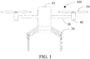
- FIG. 1 and FIG. 2 show an unmanned aerial vehicle 100 according to the first embodiment of the present invention.
- the unmanned aerial vehicle 100 may be single-rotor, dual-rotor, quad-rotor, hex-rotor, or the like.
- a detailed description is provided herein by using a quad-rotor unmanned aerial vehicle as an example.
- the unmanned aerial vehicle 100 includes an unmanned aerial vehicle body 10, a landing gear 20, an arm 30, a motor 40, and a rotor 50.
- the rotor 50 is mounted on the motor 40
- the motor 40 is mounted on one end of the arm 30, the other end of the arm 30 is mounted on the unmanned aerial vehicle body 10
- the landing gear 20 is mounted on the unmanned aerial vehicle body 10 and used for supporting the unmanned aerial vehicle 100 on a landing location when the unmanned aerial vehicle 100 lands.
- the unmanned aerial vehicle body 10 includes a control circuit assembly including electronic parts and components such as an MCU.
- the control circuit assembly includes a plurality of control modules, for example, a control module used for controlling the landing gear 20 to retract and extend, a flight control module used for controlling a flight gesture of the unmanned aerial vehicle, a BeiDou module used for navigating the unmanned aerial vehicle, and a data processing module used for processing environment information obtained by a related on-board device.
- Each of two opposite sides of the unmanned aerial vehicle body 10 is provided with two accommodation grooves 102 used for accommodating the retracted landing gears 20.
- the number of the landing gear 20 is four, each side is provided with two landing gears 20, and each accommodation groove 102 correspondingly accommodates one landing gear 20.
- the landing gear 20 may be added on each side according to a requirement.
- each side is provided with three or four landing gears 20.
- the unmanned aerial vehicle body 10 may not be provided with accommodation groove, and the landing gear are directly accommodated in the unmanned aerial vehicle body 10 as long as place for the landing gear is reserved during design of the unmanned aerial vehicle body. Setting the accommodation grooves 102 on the unmanned aerial vehicle body 10 does not occupy an internal space of the unmanned aerial vehicle body nor causes interference to the parts and components in the unmanned aerial vehicle body 10, and makes the structure of the unmanned aerial vehicle body 10 more compact.
- each accommodation groove 102 is of a strip shape and vertically disposed, and is formed by means of enclosure of a side wall 104. Thereinto, the side wall 104 is further recessed to form a groove 105.
- each landing gear 20 includes a linkage mechanism and a power apparatus driving the linkage mechanism to fold or extend.
- the above-mentioned power apparatus is mounted in the groove 105 of the side wall 104, and includes a body 202 and a rotating shaft 2026.
- a central axis of the rotating shaft 2026 is horizontally arranged.
- the power apparatus includes a steering engine.
- the steering engine includes an automatic control system including a direct current motor, a reduction gear set, a sensor, and a control circuit.
- the power apparatus may alternatively use a stepping motor, a direct current motor, an alternating current motor, or the like.
- the MCU in the unmanned aerial vehicle body 10 may control, by sending a signal, the rotating shaft 2026 to rotate by a specified angle.
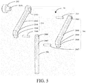
- the linkage mechanism includes at least one parallelogram mechanism. Further, the linkage mechanism includes a first rotation rod 204, a second rotation rod 206, and a support rod 208. Projections of the first rotation rod 204 and the second rotation rod 206 onto a horizontal plane parallel to axes of the first rotation rod 204 and the second rotation rod 206 are not overlapped. By means of such a non-overlapped arrangement, the landing gear can have a higher strength.
- the first rotation rod 204 is connected to the rotating shaft 2026 of the power apparatus and driven to rotate by the power apparatus.
- One end of the second rotation rod 206 is hingedly connected to the unmanned aerial vehicle body, and one end of the support rod 208 is hingedly connected to the other ends of the first rotation rod 204 and the second rotation rod 206.
- the first rotation rod 204, the second rotation rod 20, and the support rod 208 jointly form a parallelogram mechanism.
- the first rotation rod 204 is an active rod
- the second rotation rod 206 is a driven rod.
- the support rod 208 may reduce shake in a retraction or an extension process.
- the parallelogram mechanism has such advantages as a long stroke, flexible movement, high stability, high strength, and a simple structure, and can make the structure of a folded landing gear more compact after being applied to the landing gear.
- the first rotation rod 204 includes a mounting portion 2042, a first connecting rod 2040 extending from the mounting portion 2042, and a first bending portion 2044 extending from the first connecting rod 2040.
- the mounting portion 2042 is disposed on one end of the first connecting rod 2040.
- the first bending portion 2044 extends from the other end of the first connecting rod 2040, and forms a first angle with the first connecting rod 2040.
- the first bending portion 2044 is provided with a first accommodation hole 2048.
- the second rotation rod 206 includes a second connecting rod 2060 and a second bending portion 2064 extending from the second connecting rod 2060.
- One end of the second connecting rod 2060 is provided with a pin hole 2066.
- the second bending portion 2064 extends from the other end of the second connecting rod 2060 and forms a second angle with the second connecting rod 2060.
- the second bending portion 2064 is provided with a second accommodation hole 2068.
- the first angle is equal to the second angle. In this embodiment, the first angle and the second angle are both 90 degrees. In some other embodiments, the first angle and the second angle may be other degrees.
- the linkage mechanism further includes a connecting pin 210.
- One end of the connecting pin 210 is accommodated in the connecting pin hole 2066, and the other end of the connecting pin 210 is mounted on the side wall 104.
- the second rotation rod 206 is hingedly connected to the unmanned aerial vehicle body 10 by using the connecting pin 210.
- the above-mentioned support rod 208 is used for supporting the unmanned aerial vehicle 100 on the landing location, and one end of the support rod 208 is movably connected to the first bending portion 2044 and the second bending portion 2064 and sandwiched between the first bending portion 2044 and the second bending portion 2064.
- the support rod 208 is provided with a third accommodation hole 2089 and a fourth accommodation hole 2087.
- the linkage mechanism further includes a first pin roll 2049 and a second pin roll 2067. One end of the first pin roll 2049 is movably mounted in the first accommodation hole 2048, and the other end of the first pin roll 2049 is movably mounted in the third accommodation hole 2089. One end of the second pin roll 2067 is movably mounted in the second accommodation hole 2068, and the other end of the second pin roll 2067 is movably mounted in the fourth accommodation hole 2087.
- the first rotation rod 204 is provided with the first bending portion 2044
- the second rotation rod 206 is provided with the second bending portion 2064, so that the landing gear 20 has a more compact structure after retracting.
- the linkage mechanism may further include a cross rod connected to the support rod 208.
- An axis of the cross rod is perpendicular to an axis of the support rod 208.
- the cross rod can further improve the supporting stability of the landing gear.
- the MCU in the unmanned aerial vehicle body 10 controls the rotating shaft 2026 to rotate, to drive the first rotation rod 204 to rotate towards the accommodation groove 102 around a central axis of the rotating shaft 2026.
- the second rotation rod 206 also rotates towards the accommodation groove 102 around the connecting pin 210.
- the support rod 208 retracts.
- the rotating shaft 2026 stops rotating.
- the MCU in the unmanned aerial vehicle body 10 controls the rotating shaft 2026 to rotate, to drive the first rotation rod 204 to rotate around the central axis of the rotating shaft 2026 in a direction away from the accommodation groove 102.
- the second rotation rod 206 also rotates around the connecting pin 210 in the direction away from the accommodation groove 102.
- the support rod 208 is detached from the accommodation groove 102.
- the rotating shaft 2026 stops rotating. At this moment, free ends of four support rods 208 of the four landing gears 20 are located on a same horizontal plane, to support the unmanned aerial vehicle 100 in the landing location.
- the landing gear 20 in the present invention can be entirely accommodated in the accommodation groove 102 when being folded, and therefore neither causes unnecessary resistance in air nor blocks an aerial photographing field of view in an aerial photographing process of the unmanned aerial vehicle 100.
- the landing gear 20 is entirely accommodated in the accommodation groove 102, so that the unmanned aerial vehicle is very compact in structure and easy to accommodate and carry.
- the landing gear 20 further includes a buffer apparatus.
- the buffer apparatus may be a buffer spring, an air cylinder buffer apparatus, a hydraulic buffer apparatus, an oil pressure buffer apparatus, or the like.
- the buffer apparatus is mounted so that it acts on the first rotation rod 204. After the landing gear 20 of the unmanned aerial vehicle 100 is in contact with the ground, the landing gear 20 may rotate under a force.
- the buffer apparatus can provide a torsional elastic force, so that the landing gear 20 plays a role of buffering and damping, thereby avoiding damage of the unmanned aerial vehicle 100 due to an excessively fast landing speed during landing.
- the buffer apparatus is disposed on the first rotation rod 204.
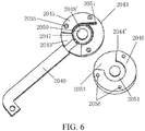
- the mounting portion 2042 includes a first part 2043 and a second part 2044' that are connected to each other.
- the buffer apparatus includes a first connecting body 2045 disposed on a surface that is of the first part 2043 and that faces the second part 2044', a second connecting body 2046 disposed on a surface that is of the second part 2044' and that faces the first part 2043, and an elastic component 2047 disposed between the first part 2043 and the second part 2044'.
- the elastic component 2047 may be a torque spring, a spring plate, or the like.
- the first connecting body 2045 is of an sector ring shape, and jointly forms, with the surface that is of the first part 2043 and that faces the second part 2044', a first groove 2048' and a first opening 2049' communicated with the first groove 2048'.
- the center of the first groove 2048' is further provided with a fixed column 2050.
- the first connecting body 2045 is of an sector ring shape, the first groove 2048' is of a circular shape, and the first opening 2049' is of a fan shape.
- the first connecting body 2045 is further provided with a long and narrow slot 2051, and the slot 2051 extends in a tangential direction of the first groove 2048' and is communicated with the first groove 2048'.
- the elastic component 2047 is sleeved on the fixed column 2050, and one end of the elastic component 2047 is located in the slot 2051 and abuts against the first connecting body 2045.
- the first connecting body 2045 may be of another shape as long as the first connecting body 2045 can jointly form an opening and a groove with the surface of the first part 2043.
- the first connecting body 2045 may further be integrated with the first part 2043.
- the shape of the second connecting body 2046 is the same as the shape of the first connecting body 2045 and is also an sector ring shape.
- the second connecting body 2046 jointly forms, with a surface that is of the second part 2044' and that faces the first part 2043, a second groove 2052 and a second opening 2053 communicated with the second groove 2052.
- the center of the second part 2044' is provided with an accommodation hole 2054 used for accommodating the fixed column 2050.
- the second connecting body 2046 may be of another shape, as long as the shape thereof is the same as the shape of the first connecting body 2045.
- the second connecting body 2046 may further be integrated with the second part 2044'.
- first connecting body 2045 is provided with a plurality of clamping columns 2055
- second connecting body 2046 is provided with a plurality of mounting holes 2056.
- the first part 2043 and the second part 2044' are fixed to each other by means of engagement of the clamping columns 2055 and the mounting holes 2056.
- first part 2043 and the second part 2044' may be connected in another connection manner, for example, bonding, threaded connection, or welding.
- the first opening 2049' and the second opening 2053 are disposed opposite to each other, and the first groove 2048' and the second groove 2054 are disposed opposite to each other, so as to form a groove used for accommodating the elastic component 2047 and a fan-shaped accommodation space.
- One end of the first connecting rod 2040 is accommodated in the accommodation space and is connected to the elastic component 2047, and may move in a range defined by the accommodation space.
- the buffer apparatus may only include the first connecting body and the elastic component.
- the first connecting body is directly disposed on a surface that is of the mounting portion and that faces the power apparatus, and the shape and the structure of the first connecting body are the same as the shape and the structure described above.
- the center of the mounting portion has no fixed column but is provided with a through hole for running through by the rotating shaft.
- the elastic component may be directly sleeved on the rotating shaft.
- the first connecting body and a surface that is of the body of the power apparatus and that faces the mounting portion jointly form an accommodation space used for accommodating one end of the first connecting rod and a groove used for accommodating the elastic component.
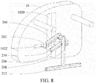
- a unmanned aerial vehicle 200 provided in the second embodiment of the present invention is basically the same as the unmanned aerial vehicle 100 provided in the first embodiment, and a difference is that: two opposite sides of a unmanned aerial vehicle body 10 are each provided with an accommodation groove 102, the accommodation groove 102 includes a vertical portion 1020 and a horizontal portion 1022. The vertical portion 1020 and the horizontal portion 1022 are communicated with each other and roughly disposed in a cross shape. There are two landing gears 20, and each side of the unmanned aerial vehicle body 10 is provided with one landing gear 20. A support rod 208 of each landing gear 20 is connected to a cross rod 212, and the cross rod 212 is horizontally disposed.
- Each landing gear 20 is provided with a cross rod 212 and two cross rods 212 of the two landing gears 20 are disposed in parallel, so as to more stably support the unmanned aerial vehicle 200 in a landing location.
- an MCU in the unmanned aerial vehicle body 10 controls a rotating shaft 2026 to rotate, to drive a first rotation rod 204 to rotate towards the accommodation groove 102 around a central axis of the rotating shaft 2026.
- a second rotation rod 206 also rotates towards the accommodation groove 102 around a connecting pin 210.
- the support rod 208 and the cross rod 212 retract.
- the MCU in the unmanned aerial vehicle body 10 controls the rotating shaft 2026 to rotate, to drive the first rotation rod 204 to rotate around the central axis of the rotating shaft 2026 in a direction away from the accommodation groove 102.
- the second rotation rod 206 also rotates around the connecting pin 210 in the direction away from the accommodation groove 102.
- the support rod 208 is detached from the vertical portion 1020, and the cross rod 212 is detached from the horizontal portion 1022.
- the rotating shaft 2026 stops rotating.
- the two cross rods 212 of the two landing gears 20 are located on a same horizontal plane, to support the unmanned aerial vehicle 200 in the landing location.
- the unmanned aerial vehicle body 10 is provided with the accommodation groove 102.
- the landing gear 20 retracts and is accommodated in the vertical portion 1020 and the horizontal portion 1022, and therefore neither causes unnecessary resistance in air nor blocks an aerial photographing field of view in an aerial photographing process of the unmanned aerial vehicle 200.
- the landing gear 20 is accommodated in the vertical portion 1020 and the horizontal portion 1022, so that the unmanned aerial vehicle is very compact in structure and easy to accommodate and carry.
- each side of the unmanned aerial vehicle body 10 may be provided with two accommodation grooves 102.
- Each accommodation groove 102 includes a vertical portion 1020, and vertical portions 1020 of the two accommodation grooves 102 are connected to a same horizontal portion 1022.
- the horizontal portion 1022 is disposed between the two vertical portions 1020, and is communicated with the two vertical portions 1020.
- the horizontal portion 1022 and the two vertical portions 1020 are roughly disposed in an H shape.
- One landing gear 20 in the first embodiment shown in FIG. 1 to FIG. 5 is mounted in each of the two vertical portions 1020.
- Two landing gears 20 on a same side of the unmanned aerial vehicle body 10 share one cross rod 212, that is, two ends of the cross rod 212 may be connected between end portions of two support rods 208, or may be connected between middle parts of the two support rods 208.
- two ends of the horizontal portion 1022 run through the two vertical portions 1020, and two landing gears 20 on a same side of the unmanned aerial vehicle body 10 share one cross rod 212, that is, end portions of two support rods 208 are connected to the cross rod 212.
- the vertical portion 1020 accommodates the first rotation rod 204, the second rotation rod 206, and the support rod 208, and the horizontal portion 1022 accommodates the cross rod 212.
- the stability of the landing gears 20 may be improved.
- the landing gear 20 can still retracts and extends normally.
Landscapes
- Engineering & Computer Science (AREA)
- Aviation & Aerospace Engineering (AREA)
- Mechanical Engineering (AREA)
- Toys (AREA)
- Automatic Assembly (AREA)
Claims (9)
- Unbemanntes Luftfahrzeug (100), umfassend:eine unbemannte Luftfahrzeugkarosserie (10); undein klappbares Fahrwerk (20), das mit der unbemannten Luftfahrzeugkarosserie (10) verbunden ist, wobei das Fahrwerk (20) vollständig in einer äußeren Kontur der unbemannten Luftfahrzeugkarosserie (10) aufgenommen ist, wenn es sich in einem zusammengeklappten Zustand befindet;wobei das Fahrwerk (20) Folgendes umfasst:einen Gestängemechanismus, der mindestens einen Parallelogrammmechanismus umfasst; undeine Leistungsvorrichtung, die zum Antrieb des Gestängemechanismus zum Zusammenklappen oder Aufklappen verwendet wird, wobei die Leistungsvorrichtung mit der unbemannten Luftfahrzeugkarosserie (10) verbunden ist und die Leistungsvorrichtung einen Körper (202), eine mit dem Körper (202) verbundene rotierende Welle (2026) und eine Puffervorrichtung umfasst;wobei der Parallelogrammmechanismus Folgendes umfasst:eine erste Rotationsstange (204), wobei ein Ende der ersten Rotationsstange (204) mit der Leistungsvorrichtung verbunden ist;eine zweite Rotationsstange (206), die parallel zu der ersten Rotationsstange (204) angeordnet ist, wobei ein Ende der zweiten Rotationsstange (206) gelenkig mit der unbemannten Luftfahrzeugkarosserie (10) verbunden ist; undeine Stützstange (208), die zwischen der ersten Rotationsstange (204) und der zweiten Rotationsstange (206) montiert ist, wobei ein Ende der Stützstange (208) gelenkig mit dem anderen Ende der ersten Rotationsstange (204) und dem anderen Ende der zweiten Rotationsstange (206) verbunden ist;wobei die erste Rotationsstange (204) einen Montageabschnitt (2042), der auf die rotierende Welle (2026) der Leistungsvorrichtung aufgeschoben ist, eine erste Verbindungsstange (2040), die sich von dem Montageabschnitt (2042) erstreckt, und einen ersten Biegeabschnitt (2044), der an einem hinteren Ende der ersten Verbindungsstange (2040) gebogen ist, umfasst;wobei die zweite Rotationsstange (206) eine zweite Verbindungsstange (2060), deren eines Ende gelenkig mit der unbemannten Luftfahrzeugkarosserie (10) verbunden ist, und einen zweiten Biegeabschnitt (2064), der an einem hinteren Ende der zweiten Verbindungsstange (2060) gebogen ist, umfasst; undwobei der erste Biegeabschnitt (2044) und der zweite Biegeabschnitt (2064) beide gelenkig mit der Stützstange (208) verbunden sind;wobei die Puffervorrichtung einen ersten Verbindungskörper (2045), der auf einer Oberfläche des Montageabschnitts (2042) angeordnet ist, die dem Körper (202) zugewandt ist, und eine elastische Komponente (2047), die auf die rotierende Welle (2026) aufgeschoben ist, umfasst;der erste Verbindungskörper (2045) und die Oberfläche des Montageabschnitts (2042), die dem Körper (202) zugewandt ist, zusammen eine Nut bilden, die zur Aufnahme der elastischen Komponente verwendet wird, und der erste Verbindungskörper (2045) eine Öffnung aufweist, die mit der Nut kommuniziert; undein Ende der ersten Verbindungsstange (2040) mit der elastischen Komponente (2047) verbunden ist und sich in einem Raum befindet, der von der Öffnung und einer Oberfläche des Körpers (202) eingefasst und dem Montageabschnitt (2042) zugewandt ist; und ein Ende der elastischen Komponente (2047) mit der ersten Verbindungsstange (2040) verbunden ist und das andere Ende der elastischen Komponente (2047) an dem ersten Verbindungskörper (2045) anliegt.
- Unbemanntes Luftfahrzeug nach Anspruch 1, wobei die unbemannte Luftfahrzeugkarosserie (10) ferner mit Aufnahmenuten (102) versehen ist, die zur Aufnahme der Fahrwerke (20) verwendet werden, und die Aufnahmenuten (102) mittels Einfassung einer Seitenwand (104) der unbemannten Luftfahrzeugkarosserie (10) ausgebildet sind, und die Seitenwand (104) mit Aufnahmeabschnitten versehen ist, die zur Aufnahme der Leistungsvorrichtungen verwendet werden.
- Unbemanntes Luftfahrzeug nach Anspruch 1, wobei der erste Verbindungskörper (2045) ferner mit einem Schlitz (2051) versehen ist, der mit der Nut kommuniziert, und das andere Ende der elastischen Komponente (2047) sich in dem Schlitz (2051) befindet und an dem ersten Verbindungskörper (2045) anliegt.
- Unbemanntes Luftfahrzeug nach Anspruch 3, wobei der erste Verbindungskörper (2045) sektorringförmig ist, so dass die Öffnung fächerförmig und die Nut ringförmig ist, und der Schlitz (2051) sich in einer tangentialen Richtung der Nut erstreckt.
- Unbemanntes Luftfahrzeug, umfassend:eine unbemannte Luftfahrzeugkarosserie (10); undein klappbares Fahrwerk (20), das mit der unbemannten Luftfahrzeugkarosserie (10) verbunden ist, wobei das Fahrwerk (20) vollständig in einer äußeren Kontur der unbemannten Luftfahrzeugkarosserie (10) aufgenommen ist, wenn es sich in einem zusammengeklappten Zustand befindet;wobei das Fahrwerk (20) Folgendes umfasst:einen Gestängemechanismus, der mindestens einen Parallelogrammmechanismus umfasst; undeine Leistungsvorrichtung, die zum Antrieb des Gestängemechanismus zum Zusammenklappen oder Aufklappen verwendet wird, wobei die Leistungsvorrichtung mit der unbemannten Luftfahrzeugkarosserie (10) verbunden ist und die Leistungsvorrichtung einen Körper (202), eine mit dem Körper (202) verbundene rotierende Welle (2026) und eine Puffervorrichtung umfasst;wobei der Parallelogrammmechanismus Folgendes umfasst:eine erste Rotationsstange (204), wobei ein Ende der ersten Rotationsstange (204) mit der Leistungsvorrichtung verbunden ist;eine zweite Rotationsstange (206), die parallel zu der ersten Rotationsstange (204) angeordnet ist, wobei ein Ende der zweiten Rotationsstange (206) gelenkig mit der unbemannten Luftfahrzeugkarosserie (10) verbunden ist; undeine Stützstange (208), die zwischen der ersten Rotationsstange (204) und der zweiten Rotationsstange (206) montiert ist, wobei ein Ende der Stützstange (208) gelenkig mit dem anderen Ende der ersten Rotationsstange (204) und dem anderen Ende der zweiten Rotationsstange (206) verbunden ist;wobei die erste Rotationsstange (204) einen Montageabschnitt (2042), der mit der rotierenden Welle (2026) der Leistungsvorrichtung verbunden ist, eine erste Verbindungsstange (2040), die sich von dem Montageabschnitt (2042) aus erstreckt, und einen ersten Biegeabschnitt (2044), der an einem hinteren Ende der ersten Verbindungsstange (2040) gebogen ist, umfasst, wobei der Montageabschnitt (2042) einen ersten Teil (2043) und einen zweiten Teil (2044') umfasst, die ineinander eingepasst sind;wobei die zweite Rotationsstange (206) eine zweite Verbindungsstange (2060), deren eines Ende gelenkig mit der unbemannten Luftfahrzeugkarosserie (10) verbunden ist, und einen zweiten Biegeabschnitt (2064), der an einem hinteren Ende der zweiten Verbindungsstange (2060) gebogen ist, umfasst; undwobei der erste Biegeabschnitt (2044) und der zweite Biegeabschnitt (2064) beide gelenkig mit der Stützstange (208) verbunden sind;wobei die Puffervorrichtung einen ersten Verbindungskörper (2045), der auf einer Oberfläche des ersten Teils (2043) angeordnet ist, die dem zweiten Teil (2044') zugewandt ist, einen zweiten Verbindungskörper (2046), der auf einer Oberfläche des zweiten Teils (2044') angeordnet ist, die dem ersten Teil (2043) zugewandt ist, und eine elastische Komponente (2047,) die zwischen dem ersten Teil (2043) und dem zweiten Teil (2044') angeordnet ist, umfasst;der erste Verbindungskörper (2045) und der erste Teil (2043) zusammen eine erste Nut (2048') bilden, wobei eine feste Säule (2050) in der ersten Nut (2048') angeordnet ist, und der erste Verbindungskörper (2045) ferner eine erste Öffnung (2049') umfasst, die mit der ersten Nut (2048') kommuniziert;der zweite Verbindungskörper (2046) und der zweite Teil (2044') zusammen eine zweite Nut (2052) bilden, wobei in der zweiten Nut (2052) ein zur Aufnahme der festen Säule (2050) verwendetes Aufnahmeloch (2054) ausgebildet ist, und der zweite Verbindungskörper (2046) ferner eine zweite Öffnung (2053) umfasst, die mit der zweiten Nut (2052) kommuniziert;der erste Teil (2043) in den zweiten Teil (2044') eingepasst ist, so dass die erste Nut (2048') und die zweite Nut (2052) zusammen eine Nut bilden, die zur Aufnahme der elastischen Komponente (2047) dient, und die erste Öffnung (2049') und die zweite Öffnung (2053) zusammen einen Aufnahmeraum bilden; undein Ende der ersten Rotationsstange (204) in dem Aufnahmeraum aufgenommen ist und ein Ende der elastischen Komponente (2047) mit der ersten Rotationsstange (204) verbunden ist und das andere Ende der elastischen Komponente (2047) an dem ersten Verbindungskörper (2045) anliegt.
- Unbemanntes Luftfahrzeug nach Anspruch 5, wobei der erste Verbindungskörper (2045) ferner mit einem Schlitz (2051) versehen ist, der mit der ersten Nut (2048') kommuniziert, und das andere Ende der elastischen Komponente (2047) sich in dem Schlitz (2051) befindet und an dem ersten Verbindungskörper (2045) anliegt.
- Unbemanntes Luftfahrzeug nach Anspruch 6, wobei der erste Verbindungskörper (2045) sektorringförmig ist, so dass die erste Öffnung (2049') fächerförmig und die erste Nut (2048') ringförmig ist, und der Schlitz (2051) sich in einer tangentialen Richtung der ersten Nut (2048') erstreckt.
- Unbemanntes Luftfahrzeug nach Anspruch 7, wobei der zweite Verbindungskörper (2046) und der erste Verbindungskörper (2045) die gleiche Form aufweisen.
- Unbemanntes Luftfahrzeug nach einem der Ansprüche 5 bis 8, wobei der erste Verbindungskörper (2045) mit einer Klemmsäule (2055) versehen ist, der zweite Verbindungskörper (2046) mit einem Montageloch (2056) versehen ist, das mit der Klemmsäule (2055) in Eingriff steht, und der erste Verbindungskörper (2045) mit dem zweiten Verbindungskörper (2046) durch ein Zusammenwirken zwischen der Klemmsäule (2055) und dem Montageloch (2056) befestigt ist.
Applications Claiming Priority (2)
| Application Number | Priority Date | Filing Date | Title |
|---|---|---|---|
| CN201611236880.8A CN106741876B (zh) | 2016-12-28 | 2016-12-28 | 一种无人机 |
| PCT/CN2017/099716 WO2018120890A1 (zh) | 2016-12-28 | 2017-08-30 | 一种无人机 |
Publications (3)
| Publication Number | Publication Date |
|---|---|
| EP3366577A1 EP3366577A1 (de) | 2018-08-29 |
| EP3366577A4 EP3366577A4 (de) | 2019-04-03 |
| EP3366577B1 true EP3366577B1 (de) | 2020-07-01 |
Family
ID=58924863
Family Applications (1)
| Application Number | Title | Priority Date | Filing Date |
|---|---|---|---|
| EP17814291.5A Active EP3366577B1 (de) | 2016-12-28 | 2017-08-30 | Unbemanntes luftfahrzeug |
Country Status (4)
| Country | Link |
|---|---|
| US (1) | US11091249B2 (de) |
| EP (1) | EP3366577B1 (de) |
| CN (1) | CN106741876B (de) |
| WO (1) | WO2018120890A1 (de) |
Families Citing this family (16)
| Publication number | Priority date | Publication date | Assignee | Title |
|---|---|---|---|---|
| CN106741876B (zh) | 2016-12-28 | 2022-07-29 | 深圳市道通智能航空技术股份有限公司 | 一种无人机 |
| US11459094B2 (en) * | 2017-09-29 | 2022-10-04 | Georgia Tech Research Corporation | Cable-driven four-bar link leg mechanism |
| WO2020019350A1 (zh) * | 2018-07-27 | 2020-01-30 | 深圳市大疆创新科技有限公司 | 无人机控制方法、装置及无人机 |
| CN109533298A (zh) * | 2018-12-06 | 2019-03-29 | 徐州创航科技有限公司 | 一种便于收纳的无人机用起落架 |
| KR102088336B1 (ko) * | 2019-11-29 | 2020-03-12 | 김몽룡 | 수직정렬 보조휠을 구비한 모터사이클용 랜딩장치 |
| CN112027067B (zh) * | 2020-09-08 | 2021-12-31 | 广州众悦科技有限公司 | 一种无人机的防护机构 |
| CN112758327A (zh) * | 2021-03-16 | 2021-05-07 | 广东海洋大学 | 一种新型载人无人机 |
| CN112977805B (zh) * | 2021-04-19 | 2022-07-15 | 北京航空航天大学 | 一种微小型扑翼飞行器用着陆装置 |
| KR102561823B1 (ko) * | 2021-06-30 | 2023-08-02 | 주식회사 드론프릭 | 캐리어 드론 |
| CN114136294B (zh) * | 2021-11-26 | 2022-08-16 | 山东省物化探勘查院 | 智能化三维地形测绘装置 |
| CN114162313A (zh) * | 2021-12-29 | 2022-03-11 | 浙江东田科技有限公司 | 一种用于农业监测的移动无人机 |
| CN114408366B (zh) * | 2022-01-28 | 2023-09-08 | 重庆零壹空间航天科技有限公司 | 一种无人直升机运输方舱 |
| CN114476035B (zh) * | 2022-02-08 | 2023-05-02 | 中交二公局第三工程有限公司 | 一种无人机用的起落架 |
| CN115503940B (zh) * | 2022-11-09 | 2024-09-06 | 哈尔滨工业大学 | 一种应用于无人飞行器的自适应腿式起落架 |
| US12304669B2 (en) | 2023-07-31 | 2025-05-20 | Drone Amplified, Inc. | Drone landing gear |
| CN118062297B (zh) * | 2024-03-28 | 2025-09-16 | 江西翱翔星云科技有限公司 | 一种可柔性定位的车载无人机起落架 |
Family Cites Families (19)
| Publication number | Priority date | Publication date | Assignee | Title |
|---|---|---|---|---|
| GB478778A (en) * | 1936-02-24 | 1938-01-25 | Mercier Jean | Retractable landing gear of aeroplanes |
| US2215598A (en) * | 1938-08-15 | 1940-09-24 | Bernard W Sznycer | Ski for retractable undercarriages |
| GB726573A (en) * | 1952-03-20 | 1955-03-23 | Sncase | Improvements in or relating to aircraft landing gear |
| US2752112A (en) * | 1953-03-31 | 1956-06-26 | North American Aviation Inc | Steerable and retractable aircraft landing gear |
| RU1213659C (ru) * | 1984-07-19 | 1995-07-20 | Самарское государственное предприятие "Авиаагрегат" | Убирающееся лыжное шасси летательного аппарата |
| GB0804078D0 (en) * | 2008-03-05 | 2008-04-09 | Airbus Uk Ltd | Landing gear with composite leaf spring |
| US8774982B2 (en) * | 2010-08-26 | 2014-07-08 | Leptron Industrial Robotic Helicopters, Inc. | Helicopter with multi-rotors and wireless capability |
| CN203294310U (zh) * | 2013-04-27 | 2013-11-20 | 湖北易瓦特科技有限公司 | 无人机可收放式起落架 |
| CN203638090U (zh) * | 2014-01-10 | 2014-06-11 | 江苏艾锐泰克无人飞行器科技有限公司 | 起落架 |
| CN103754355A (zh) * | 2014-01-10 | 2014-04-30 | 江苏艾锐泰克无人飞行器科技有限公司 | 收放起落架及无人飞行器 |
| CN104260605A (zh) * | 2014-10-16 | 2015-01-07 | 北京理工大学 | 一种基于变胞原理的陆空两栖球形变胞机器人 |
| US9731816B2 (en) * | 2014-12-08 | 2017-08-15 | The Boeing Company | Multi-position landing gear |
| CN204871592U (zh) * | 2015-06-10 | 2015-12-16 | 深圳九星智能航空科技有限公司 | 旋翼臂内设置可折叠起落杆的无人飞行器 |
| CN204871591U (zh) * | 2015-07-17 | 2015-12-16 | 零度智控(北京)智能科技有限公司 | 一种飞行器可收放起落架及飞行器 |
| CN204846362U (zh) * | 2015-07-23 | 2015-12-09 | 致导科技(北京)有限公司 | 一种无人机起落架及具有其的无人机 |
| CN205574264U (zh) * | 2016-04-08 | 2016-09-14 | 北京博瑞空间科技发展有限公司 | 起落架结构和无人机 |
| CN205707370U (zh) * | 2016-05-25 | 2016-11-23 | 江西科技学院 | 便携式可折叠无人机 |
| CN106741876B (zh) * | 2016-12-28 | 2022-07-29 | 深圳市道通智能航空技术股份有限公司 | 一种无人机 |
| CN206561942U (zh) * | 2016-12-28 | 2017-10-17 | 深圳市道通智能航空技术有限公司 | 一种无人机 |
-
2016
- 2016-12-28 CN CN201611236880.8A patent/CN106741876B/zh active Active
-
2017
- 2017-08-30 EP EP17814291.5A patent/EP3366577B1/de active Active
- 2017-08-30 WO PCT/CN2017/099716 patent/WO2018120890A1/zh not_active Ceased
- 2017-12-18 US US15/845,372 patent/US11091249B2/en active Active
Non-Patent Citations (1)
| Title |
|---|
| None * |
Also Published As
| Publication number | Publication date |
|---|---|
| US20180194458A1 (en) | 2018-07-12 |
| EP3366577A4 (de) | 2019-04-03 |
| US11091249B2 (en) | 2021-08-17 |
| CN106741876A (zh) | 2017-05-31 |
| CN106741876B (zh) | 2022-07-29 |
| WO2018120890A1 (zh) | 2018-07-05 |
| EP3366577A1 (de) | 2018-08-29 |
Similar Documents
| Publication | Publication Date | Title |
|---|---|---|
| US11091249B2 (en) | Unmanned aerial vehicle | |
| CN114212242B (zh) | 无人飞行器 | |
| JP6343799B2 (ja) | 移動体又は玩具移動体のためのプロパルジョンシステム | |
| RU2555375C2 (ru) | Убирающееся посадочное шасси вертолета | |
| CN109204786B (zh) | 一种起落架及具有此起落架的无人机 | |
| RU2520266C1 (ru) | Основное шасси летательного аппарата, содержащее два балансира, шарнирно соединенных с конструкцией летательного аппарата | |
| EP3632793B1 (de) | Unbemanntes luftfahrzeug und fahrwerk dafür | |
| CN109383739B (zh) | 一种机臂及无人机 | |
| CN103029120A (zh) | 一种折叠式静载平衡并联调姿平台 | |
| CN110871883B (zh) | 一种筒射无人机机翼折叠展开机构 | |
| BRPI0611902A2 (pt) | dispositivo de direção para trem de pouso de aeronave | |
| US20140014425A1 (en) | In-wheel motor apparatus | |
| CN108513555B (zh) | 可折叠机架、机架组件及无人飞行器 | |
| CN112208673A (zh) | 一种全向运动机器人 | |
| DE112019002947T5 (de) | Fahrzeugantriebsstrang mit gelenkigen radmotoren | |
| CN221341094U (zh) | 一种复合结构球平衡飞行器 | |
| CN219191842U (zh) | 一种可变形空地两栖机器人 | |
| CN112572088B (zh) | 一种轮距可调型全轮转向机器人底盘 | |
| CN206719520U (zh) | 可折叠机架、机架组件及无人飞行器 | |
| CN205819538U (zh) | 无人机 | |
| CN204916166U (zh) | 脚架及无人机 | |
| CN115158698A (zh) | 一种利用下斜盘操纵的共轴双旋翼式火星飞行器 | |
| CN112357056A (zh) | 机翼折叠机构、机翼装置及无人机 | |
| CN208963312U (zh) | 一种可折叠的三旋翼混合布局无人机 | |
| CN218537086U (zh) | 一种测绘航空摄影飞行器 |
Legal Events
| Date | Code | Title | Description |
|---|---|---|---|
| STAA | Information on the status of an ep patent application or granted ep patent |
Free format text: STATUS: UNKNOWN |
|
| STAA | Information on the status of an ep patent application or granted ep patent |
Free format text: STATUS: THE INTERNATIONAL PUBLICATION HAS BEEN MADE |
|
| PUAI | Public reference made under article 153(3) epc to a published international application that has entered the european phase |
Free format text: ORIGINAL CODE: 0009012 |
|
| STAA | Information on the status of an ep patent application or granted ep patent |
Free format text: STATUS: THE APPLICATION HAS BEEN PUBLISHED |
|
| AK | Designated contracting states |
Kind code of ref document: A1 Designated state(s): AL AT BE BG CH CY CZ DE DK EE ES FI FR GB GR HR HU IE IS IT LI LT LU LV MC MK MT NL NO PL PT RO RS SE SI SK SM TR |
|
| AX | Request for extension of the european patent |
Extension state: BA ME |
|
| STAA | Information on the status of an ep patent application or granted ep patent |
Free format text: STATUS: REQUEST FOR EXAMINATION WAS MADE |
|
| 17P | Request for examination filed |
Effective date: 20171228 |
|
| RBV | Designated contracting states (corrected) |
Designated state(s): AL AT BE BG CH CY CZ DE DK EE ES FI FR GB GR HR HU IE IS IT LI LT LU LV MC MK MT NL NO PL PT RO RS SE SI SK SM TR |
|
| A4 | Supplementary search report drawn up and despatched |
Effective date: 20190304 |
|
| RIC1 | Information provided on ipc code assigned before grant |
Ipc: B64C 25/52 20060101ALI20190226BHEP Ipc: B64C 25/32 20060101ALN20190226BHEP Ipc: B64C 25/12 20060101AFI20190226BHEP |
|
| REG | Reference to a national code |
Ref country code: DE Ref legal event code: R079 Ref document number: 602017019162 Country of ref document: DE Free format text: PREVIOUS MAIN CLASS: B64C0025100000 Ipc: B64C0025120000 |
|
| GRAJ | Information related to disapproval of communication of intention to grant by the applicant or resumption of examination proceedings by the epo deleted |
Free format text: ORIGINAL CODE: EPIDOSDIGR1 |
|
| STAA | Information on the status of an ep patent application or granted ep patent |
Free format text: STATUS: GRANT OF PATENT IS INTENDED |
|
| RIC1 | Information provided on ipc code assigned before grant |
Ipc: B64C 25/32 20060101ALN20191212BHEP Ipc: B64C 25/52 20060101ALI20191212BHEP Ipc: B64C 25/12 20060101AFI20191212BHEP |
|
| GRAP | Despatch of communication of intention to grant a patent |
Free format text: ORIGINAL CODE: EPIDOSNIGR1 |
|
| DAV | Request for validation of the european patent (deleted) | ||
| DAX | Request for extension of the european patent (deleted) | ||
| INTG | Intention to grant announced |
Effective date: 20200122 |
|
| GRAS | Grant fee paid |
Free format text: ORIGINAL CODE: EPIDOSNIGR3 |
|
| GRAA | (expected) grant |
Free format text: ORIGINAL CODE: 0009210 |
|
| STAA | Information on the status of an ep patent application or granted ep patent |
Free format text: STATUS: THE PATENT HAS BEEN GRANTED |
|
| AK | Designated contracting states |
Kind code of ref document: B1 Designated state(s): AL AT BE BG CH CY CZ DE DK EE ES FI FR GB GR HR HU IE IS IT LI LT LU LV MC MK MT NL NO PL PT RO RS SE SI SK SM TR |
|
| REG | Reference to a national code |
Ref country code: CH Ref legal event code: EP Ref country code: AT Ref legal event code: REF Ref document number: 1285947 Country of ref document: AT Kind code of ref document: T Effective date: 20200715 |
|
| REG | Reference to a national code |
Ref country code: IE Ref legal event code: FG4D |
|
| REG | Reference to a national code |
Ref country code: DE Ref legal event code: R096 Ref document number: 602017019162 Country of ref document: DE |
|
| REG | Reference to a national code |
Ref country code: LT Ref legal event code: MG4D |
|
| PG25 | Lapsed in a contracting state [announced via postgrant information from national office to epo] |
Ref country code: BG Free format text: LAPSE BECAUSE OF FAILURE TO SUBMIT A TRANSLATION OF THE DESCRIPTION OR TO PAY THE FEE WITHIN THE PRESCRIBED TIME-LIMIT Effective date: 20201001 |
|
| REG | Reference to a national code |
Ref country code: NL Ref legal event code: MP Effective date: 20200701 |
|
| REG | Reference to a national code |
Ref country code: AT Ref legal event code: MK05 Ref document number: 1285947 Country of ref document: AT Kind code of ref document: T Effective date: 20200701 |
|
| PG25 | Lapsed in a contracting state [announced via postgrant information from national office to epo] |
Ref country code: PT Free format text: LAPSE BECAUSE OF FAILURE TO SUBMIT A TRANSLATION OF THE DESCRIPTION OR TO PAY THE FEE WITHIN THE PRESCRIBED TIME-LIMIT Effective date: 20201102 Ref country code: HR Free format text: LAPSE BECAUSE OF FAILURE TO SUBMIT A TRANSLATION OF THE DESCRIPTION OR TO PAY THE FEE WITHIN THE PRESCRIBED TIME-LIMIT Effective date: 20200701 Ref country code: AT Free format text: LAPSE BECAUSE OF FAILURE TO SUBMIT A TRANSLATION OF THE DESCRIPTION OR TO PAY THE FEE WITHIN THE PRESCRIBED TIME-LIMIT Effective date: 20200701 Ref country code: LT Free format text: LAPSE BECAUSE OF FAILURE TO SUBMIT A TRANSLATION OF THE DESCRIPTION OR TO PAY THE FEE WITHIN THE PRESCRIBED TIME-LIMIT Effective date: 20200701 Ref country code: GR Free format text: LAPSE BECAUSE OF FAILURE TO SUBMIT A TRANSLATION OF THE DESCRIPTION OR TO PAY THE FEE WITHIN THE PRESCRIBED TIME-LIMIT Effective date: 20201002 Ref country code: NO Free format text: LAPSE BECAUSE OF FAILURE TO SUBMIT A TRANSLATION OF THE DESCRIPTION OR TO PAY THE FEE WITHIN THE PRESCRIBED TIME-LIMIT Effective date: 20201001 Ref country code: ES Free format text: LAPSE BECAUSE OF FAILURE TO SUBMIT A TRANSLATION OF THE DESCRIPTION OR TO PAY THE FEE WITHIN THE PRESCRIBED TIME-LIMIT Effective date: 20200701 Ref country code: CZ Free format text: LAPSE BECAUSE OF FAILURE TO SUBMIT A TRANSLATION OF THE DESCRIPTION OR TO PAY THE FEE WITHIN THE PRESCRIBED TIME-LIMIT Effective date: 20200701 Ref country code: FI Free format text: LAPSE BECAUSE OF FAILURE TO SUBMIT A TRANSLATION OF THE DESCRIPTION OR TO PAY THE FEE WITHIN THE PRESCRIBED TIME-LIMIT Effective date: 20200701 Ref country code: SE Free format text: LAPSE BECAUSE OF FAILURE TO SUBMIT A TRANSLATION OF THE DESCRIPTION OR TO PAY THE FEE WITHIN THE PRESCRIBED TIME-LIMIT Effective date: 20200701 |
|
| PG25 | Lapsed in a contracting state [announced via postgrant information from national office to epo] |
Ref country code: LV Free format text: LAPSE BECAUSE OF FAILURE TO SUBMIT A TRANSLATION OF THE DESCRIPTION OR TO PAY THE FEE WITHIN THE PRESCRIBED TIME-LIMIT Effective date: 20200701 Ref country code: PL Free format text: LAPSE BECAUSE OF FAILURE TO SUBMIT A TRANSLATION OF THE DESCRIPTION OR TO PAY THE FEE WITHIN THE PRESCRIBED TIME-LIMIT Effective date: 20200701 Ref country code: RS Free format text: LAPSE BECAUSE OF FAILURE TO SUBMIT A TRANSLATION OF THE DESCRIPTION OR TO PAY THE FEE WITHIN THE PRESCRIBED TIME-LIMIT Effective date: 20200701 Ref country code: IS Free format text: LAPSE BECAUSE OF FAILURE TO SUBMIT A TRANSLATION OF THE DESCRIPTION OR TO PAY THE FEE WITHIN THE PRESCRIBED TIME-LIMIT Effective date: 20201101 |
|
| PG25 | Lapsed in a contracting state [announced via postgrant information from national office to epo] |
Ref country code: NL Free format text: LAPSE BECAUSE OF FAILURE TO SUBMIT A TRANSLATION OF THE DESCRIPTION OR TO PAY THE FEE WITHIN THE PRESCRIBED TIME-LIMIT Effective date: 20200701 Ref country code: MC Free format text: LAPSE BECAUSE OF FAILURE TO SUBMIT A TRANSLATION OF THE DESCRIPTION OR TO PAY THE FEE WITHIN THE PRESCRIBED TIME-LIMIT Effective date: 20200701 |
|
| REG | Reference to a national code |
Ref country code: CH Ref legal event code: PL |
|
| REG | Reference to a national code |
Ref country code: DE Ref legal event code: R097 Ref document number: 602017019162 Country of ref document: DE |
|
| PG25 | Lapsed in a contracting state [announced via postgrant information from national office to epo] |
Ref country code: LI Free format text: LAPSE BECAUSE OF NON-PAYMENT OF DUE FEES Effective date: 20200831 Ref country code: LU Free format text: LAPSE BECAUSE OF NON-PAYMENT OF DUE FEES Effective date: 20200830 Ref country code: SM Free format text: LAPSE BECAUSE OF FAILURE TO SUBMIT A TRANSLATION OF THE DESCRIPTION OR TO PAY THE FEE WITHIN THE PRESCRIBED TIME-LIMIT Effective date: 20200701 Ref country code: IT Free format text: LAPSE BECAUSE OF FAILURE TO SUBMIT A TRANSLATION OF THE DESCRIPTION OR TO PAY THE FEE WITHIN THE PRESCRIBED TIME-LIMIT Effective date: 20200701 Ref country code: RO Free format text: LAPSE BECAUSE OF FAILURE TO SUBMIT A TRANSLATION OF THE DESCRIPTION OR TO PAY THE FEE WITHIN THE PRESCRIBED TIME-LIMIT Effective date: 20200701 Ref country code: CH Free format text: LAPSE BECAUSE OF NON-PAYMENT OF DUE FEES Effective date: 20200831 Ref country code: DK Free format text: LAPSE BECAUSE OF FAILURE TO SUBMIT A TRANSLATION OF THE DESCRIPTION OR TO PAY THE FEE WITHIN THE PRESCRIBED TIME-LIMIT Effective date: 20200701 Ref country code: EE Free format text: LAPSE BECAUSE OF FAILURE TO SUBMIT A TRANSLATION OF THE DESCRIPTION OR TO PAY THE FEE WITHIN THE PRESCRIBED TIME-LIMIT Effective date: 20200701 |
|
| PLBE | No opposition filed within time limit |
Free format text: ORIGINAL CODE: 0009261 |
|
| STAA | Information on the status of an ep patent application or granted ep patent |
Free format text: STATUS: NO OPPOSITION FILED WITHIN TIME LIMIT |
|
| REG | Reference to a national code |
Ref country code: BE Ref legal event code: MM Effective date: 20200831 |
|
| PG25 | Lapsed in a contracting state [announced via postgrant information from national office to epo] |
Ref country code: AL Free format text: LAPSE BECAUSE OF FAILURE TO SUBMIT A TRANSLATION OF THE DESCRIPTION OR TO PAY THE FEE WITHIN THE PRESCRIBED TIME-LIMIT Effective date: 20200701 |
|
| 26N | No opposition filed |
Effective date: 20210406 |
|
| PG25 | Lapsed in a contracting state [announced via postgrant information from national office to epo] |
Ref country code: SK Free format text: LAPSE BECAUSE OF FAILURE TO SUBMIT A TRANSLATION OF THE DESCRIPTION OR TO PAY THE FEE WITHIN THE PRESCRIBED TIME-LIMIT Effective date: 20200701 |
|
| PG25 | Lapsed in a contracting state [announced via postgrant information from national office to epo] |
Ref country code: SI Free format text: LAPSE BECAUSE OF FAILURE TO SUBMIT A TRANSLATION OF THE DESCRIPTION OR TO PAY THE FEE WITHIN THE PRESCRIBED TIME-LIMIT Effective date: 20200701 Ref country code: IE Free format text: LAPSE BECAUSE OF NON-PAYMENT OF DUE FEES Effective date: 20200830 Ref country code: BE Free format text: LAPSE BECAUSE OF NON-PAYMENT OF DUE FEES Effective date: 20200831 |
|
| PG25 | Lapsed in a contracting state [announced via postgrant information from national office to epo] |
Ref country code: TR Free format text: LAPSE BECAUSE OF FAILURE TO SUBMIT A TRANSLATION OF THE DESCRIPTION OR TO PAY THE FEE WITHIN THE PRESCRIBED TIME-LIMIT Effective date: 20200701 Ref country code: MT Free format text: LAPSE BECAUSE OF FAILURE TO SUBMIT A TRANSLATION OF THE DESCRIPTION OR TO PAY THE FEE WITHIN THE PRESCRIBED TIME-LIMIT Effective date: 20200701 Ref country code: CY Free format text: LAPSE BECAUSE OF FAILURE TO SUBMIT A TRANSLATION OF THE DESCRIPTION OR TO PAY THE FEE WITHIN THE PRESCRIBED TIME-LIMIT Effective date: 20200701 |
|
| PG25 | Lapsed in a contracting state [announced via postgrant information from national office to epo] |
Ref country code: MK Free format text: LAPSE BECAUSE OF FAILURE TO SUBMIT A TRANSLATION OF THE DESCRIPTION OR TO PAY THE FEE WITHIN THE PRESCRIBED TIME-LIMIT Effective date: 20200701 |
|
| PGFP | Annual fee paid to national office [announced via postgrant information from national office to epo] |
Ref country code: GB Payment date: 20240826 Year of fee payment: 8 |
|
| PGFP | Annual fee paid to national office [announced via postgrant information from national office to epo] |
Ref country code: DE Payment date: 20250820 Year of fee payment: 9 |
|
| PGFP | Annual fee paid to national office [announced via postgrant information from national office to epo] |
Ref country code: FR Payment date: 20250828 Year of fee payment: 9 |
|
| GBPC | Gb: european patent ceased through non-payment of renewal fee |
Effective date: 20250830 |