EP3366525A1 - Parkwegberechnungsvorrichtung, parkunterstützungsvorrichtung und parkwegberechnungsverfahren - Google Patents
Parkwegberechnungsvorrichtung, parkunterstützungsvorrichtung und parkwegberechnungsverfahren Download PDFInfo
- Publication number
- EP3366525A1 EP3366525A1 EP16857285.7A EP16857285A EP3366525A1 EP 3366525 A1 EP3366525 A1 EP 3366525A1 EP 16857285 A EP16857285 A EP 16857285A EP 3366525 A1 EP3366525 A1 EP 3366525A1
- Authority
- EP
- European Patent Office
- Prior art keywords
- parking
- axis
- vehicle
- curve
- parking path
- Prior art date
- Legal status (The legal status is an assumption and is not a legal conclusion. Google has not performed a legal analysis and makes no representation as to the accuracy of the status listed.)
- Granted
Links
- 238000004364 calculation method Methods 0.000 title claims abstract description 49
- 230000007935 neutral effect Effects 0.000 claims abstract description 12
- 238000012545 processing Methods 0.000 description 17
- 238000010586 diagram Methods 0.000 description 10
- 235000004522 Pentaglottis sempervirens Nutrition 0.000 description 4
- 238000012937 correction Methods 0.000 description 4
- 230000001133 acceleration Effects 0.000 description 2
- 238000013459 approach Methods 0.000 description 2
- 238000000034 method Methods 0.000 description 2
- 238000013461 design Methods 0.000 description 1
- 238000001514 detection method Methods 0.000 description 1
- 230000000694 effects Effects 0.000 description 1
- 238000005516 engineering process Methods 0.000 description 1
- 238000002474 experimental method Methods 0.000 description 1
- 230000002265 prevention Effects 0.000 description 1
Images


Classifications
-
- B—PERFORMING OPERATIONS; TRANSPORTING
- B62—LAND VEHICLES FOR TRAVELLING OTHERWISE THAN ON RAILS
- B62D—MOTOR VEHICLES; TRAILERS
- B62D15/00—Steering not otherwise provided for
- B62D15/02—Steering position indicators ; Steering position determination; Steering aids
- B62D15/027—Parking aids, e.g. instruction means
- B62D15/0285—Parking performed automatically
-
- B—PERFORMING OPERATIONS; TRANSPORTING
- B60—VEHICLES IN GENERAL
- B60W—CONJOINT CONTROL OF VEHICLE SUB-UNITS OF DIFFERENT TYPE OR DIFFERENT FUNCTION; CONTROL SYSTEMS SPECIALLY ADAPTED FOR HYBRID VEHICLES; ROAD VEHICLE DRIVE CONTROL SYSTEMS FOR PURPOSES NOT RELATED TO THE CONTROL OF A PARTICULAR SUB-UNIT
- B60W40/00—Estimation or calculation of non-directly measurable driving parameters for road vehicle drive control systems not related to the control of a particular sub unit, e.g. by using mathematical models
- B60W40/10—Estimation or calculation of non-directly measurable driving parameters for road vehicle drive control systems not related to the control of a particular sub unit, e.g. by using mathematical models related to vehicle motion
-
- B—PERFORMING OPERATIONS; TRANSPORTING
- B60—VEHICLES IN GENERAL
- B60R—VEHICLES, VEHICLE FITTINGS, OR VEHICLE PARTS, NOT OTHERWISE PROVIDED FOR
- B60R21/00—Arrangements or fittings on vehicles for protecting or preventing injuries to occupants or pedestrians in case of accidents or other traffic risks
-
- B—PERFORMING OPERATIONS; TRANSPORTING
- B60—VEHICLES IN GENERAL
- B60W—CONJOINT CONTROL OF VEHICLE SUB-UNITS OF DIFFERENT TYPE OR DIFFERENT FUNCTION; CONTROL SYSTEMS SPECIALLY ADAPTED FOR HYBRID VEHICLES; ROAD VEHICLE DRIVE CONTROL SYSTEMS FOR PURPOSES NOT RELATED TO THE CONTROL OF A PARTICULAR SUB-UNIT
- B60W30/00—Purposes of road vehicle drive control systems not related to the control of a particular sub-unit, e.g. of systems using conjoint control of vehicle sub-units, or advanced driver assistance systems for ensuring comfort, stability and safety or drive control systems for propelling or retarding the vehicle
- B60W30/06—Automatic manoeuvring for parking
-
- G—PHYSICS
- G05—CONTROLLING; REGULATING
- G05D—SYSTEMS FOR CONTROLLING OR REGULATING NON-ELECTRIC VARIABLES
- G05D1/00—Control of position, course or altitude of land, water, air, or space vehicles, e.g. automatic pilot
- G05D1/02—Control of position or course in two dimensions
- G05D1/021—Control of position or course in two dimensions specially adapted to land vehicles
- G05D1/0212—Control of position or course in two dimensions specially adapted to land vehicles with means for defining a desired trajectory
- G05D1/0225—Control of position or course in two dimensions specially adapted to land vehicles with means for defining a desired trajectory involving docking at a fixed facility, e.g. base station or loading bay
-
- G—PHYSICS
- G08—SIGNALLING
- G08G—TRAFFIC CONTROL SYSTEMS
- G08G1/00—Traffic control systems for road vehicles
- G08G1/14—Traffic control systems for road vehicles indicating individual free spaces in parking areas
- G08G1/141—Traffic control systems for road vehicles indicating individual free spaces in parking areas with means giving the indication of available parking spaces
- G08G1/143—Traffic control systems for road vehicles indicating individual free spaces in parking areas with means giving the indication of available parking spaces inside the vehicles
-
- G—PHYSICS
- G08—SIGNALLING
- G08G—TRAFFIC CONTROL SYSTEMS
- G08G1/00—Traffic control systems for road vehicles
- G08G1/16—Anti-collision systems
-
- G—PHYSICS
- G08—SIGNALLING
- G08G—TRAFFIC CONTROL SYSTEMS
- G08G1/00—Traffic control systems for road vehicles
- G08G1/16—Anti-collision systems
- G08G1/168—Driving aids for parking, e.g. acoustic or visual feedback on parking space
Definitions
- the present invention relates to a parking path calculation device, a parking assist device, and a parking path calculation method.
- Some type of parking path calculation device sets a parking path for perpendicular parking as a curve that is based on one-directional steering.
- An example related to the technology described above is described in Patent Literature 1.
- a virtual parking position establishing a predetermined positional relationship with a parking end position when an own vehicle is guided from an own vehicle position to the parking end position at a minimum turning radius is calculated, and depending on a positional relationship between the virtual parking position and the parking end position, a parking path on which steered wheels are to be steered to cross a neutral position thereof at a time of guiding the own vehicle is calculated.
- Fig. 1 is a configuration diagram of a vehicle to which a parking assist device is applied.
- a driver uses a shift lever 8 to instruct the vehicle to move forward or backward, or to stop, and uses an accelerator pedal 6 to specify a driving force of a drive motor 1.
- the drive motor 1 may be an engine.
- the drive motor 1 can generate a driving force and a braking force independently of accelerator pedal operation and shift operation by the driver.
- a stepping force on the brake pedal 7 is boosted by a brake booster 15, and a hydraulic pressure that depends on the stepping force is generated in a master cylinder 16.
- the generated hydraulic pressure is supplied to wheel cylinders 21 to 24 via an electric hydraulic brake 2.
- the electric hydraulic brake 2 incorporates, for example, a pump or an electromagnetic valve to be driven by a motor, and can control braking forces (hydraulic pressures of wheel cylinders 21 to 24) of four wheels independently of brake pedal operation by the driver. There is no difference between left and right braking forces of four wheels due to the brake pedal operation by the driver.
- An electric power steering 3 generates an assist torque in accordance with a steering torque input by the driver via a steering wheel 9.
- Left and right front wheels (steered wheels) 41 and 42 are steered by the steering torque of the driver and the assist torque of the electric power steering 3, and the vehicle turns during the movement. Further, the electric power steering 3 causes a steering torque independently of steering operation by the driver, and can steer the left and right front wheels 41 and 42.
- four cameras 11 to 14 configured to photograph surroundings of the vehicle to recognize objects around the vehicle are mounted at the front, left, right, and, rear positions of the vehicle, respectively. Images picked up by the four cameras 11 to 14 are synthesized for display on a touch panel 18 as a bird's eye view that looks down on the vehicle and the surroundings of the vehicle from the above. The driver can also park the vehicle while looking at the bird's eye view without parking assist control.
- the parking assist device automatically controls the drive motor 1, the electric hydraulic brake 2, and the electric power steering 3 so that the parking assist device recognizes a parking position based on a parking area and positions of other parked vehicles on images picked up by the cameras 11 to 14 and the vehicle reaches the recognized parking position.
- the driver can also indicate the parking position using the touch panel 18 displaying the bird's eye view.
- a steering angle sensor 4 and wheel speed sensors 31 to 34 are mounted in order to control the parking path.
- the electric hydraulic brake 2 performs vehicle skid prevention and anti-lock brake control using sensor signals from a vehicle motion detection sensor 17, which is configured to detect a longitudinal acceleration, a lateral acceleration, and a yaw rate, the steering angle sensor 4, and the wheel speed sensors 31 to 34.
- parking assist control also uses the signals from the steering angle sensor 4 and the wheel speed sensors 31 to 34.
- the electric devices described above are all controlled by an electronic control unit 5, and all the sensor signals are input to the electronic control unit 5.
- the sensor signals include operation amounts given by the driver, such as an accelerator pedal operation amount, a brake pedal operation amount, a shift position, and a steering torque.
- the function of the electronic control unit 5 can also be divided to implement a configuration in which an electronic control unit is mounted on each electric device and those electronic control units communicate required information to/from one another.
- the drive motor 1, the electric hydraulic brake 2, the wheel cylinders 21 to 24, the wheels 41 to 44, and the electronic control unit 5 construct an automatic vehicle speed control device configured to automatically control the vehicle speed. Further, the electric power steering 3 and the electronic control unit 5 construct an automatic steering control device configured to automatically steer the left and right front wheels 41 and 42.
- Fig. 2 is a configuration diagram of the parking assist device.
- the drive motor 1, the electric hydraulic brake 2, and the electric power steering 3 automatically control movement of the vehicle, and at the same time, the driver operation amount is monitored to enable overriding by the driver.
- the driver operates the brake pedal 7, the vehicle is temporarily stopped, and parking operation by automatic control is resumed after the driver releases the brake. With this, when an obstacle has entered the parking path, brake operation by the driver can be prioritized to avoid collision with the obstacle. After that, when operation of the brake pedal 7 is released, parking operation by automatic control is resumed. With this, when an obstacle has moved away from the parking path, it is possible to automatically resume assisting parking. Further, when the driver changes the shift position or the steering torque of the driver becomes equal to or larger than a predetermined value, parking operation by automatic control is stopped. With this, it is possible to cause the vehicle to move by prioritizing shift operation or steering operation by the driver.
- the touch panel 18 may display an automatic control stop button on the touch panel 18 so that automatic control can also be stopped by pressing the automatic control stop button.
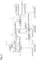
- Fig. 3 is a configuration diagram of parking assist control in the electronic control unit 5.
- the electronic control unit 5 includes a parking path calculator 51, a movement distance calculator 52, a vehicle speed calculator 53, a path controller 54, a vehicle speed controller (vehicle controller) 55, and a steering angle controller (vehicle controller) 56 as components for implementing parking assist control.
- the cameras 11 to 14 recognize a parking position at a position of starting parking operation.
- the parking position may be indicated by the driver through the touch panel 18 displaying a bird's eye view.
- the parking path calculator 51 calculates a parking path based on the parking position. The parking path is calculated when parking operation is started. The parking path is corrected successively during parking operation. Calculation and correction of the parking path are described later.
- the wheel speed sensors 31 to 34 generate a wheel speed pulse a plurality of times per rotation of the wheel.
- the number of times of generation of the wheel speed pulse is integrated for the movement distance calculator 52 to calculate a movement distance of the vehicle.
- the generation period of the wheel speed pulse is used for the vehicle speed calculator 53 to calculate a vehicle speed V.
- the movement distance and the vehicle speed V are set as a movement distance and a vehicle speed that are measured with respect to a vehicle shaft center of rear wheels, and thus average values of movement distances and wheel speeds of the left and right wheels 43 and 44 are calculated to acquire the movement distance and vehicle speed V, respectively.
- the path controller 54 calculates a vehicle speed command (target value of vehicle speed) V* and a steering angle command (target value of steering angle) ⁇ h* from the parking path and the movement distance of the vehicle.
- the vehicle speed command V* at a time when the vehicle is guided to move forward or backward is set to a fixed value.
- the vehicle speed controller 55 performs vehicle speed control based on the vehicle speed command V* and the vehicle speed V to acquire, as operation amounts, a drive torque command Tac* to be transmitted to the drive motor 1 and a hydraulic pressure command Pwc* to be transmitted to the electric hydraulic brake 2.
- the drive motor 1 and the electric hydraulic brake 2 receive those commands to generate a driving force and a braking force. Both of the driving force and the braking force may be generated only by the drive motor 1, or the driving force and the braking force may be generated by the drive motor 1 and the electric hydraulic brake 2, respectively.
- the drive motor 1 is replaced with an engine, the latter method may be adopted.
- the drive motor 1 is used instead of an engine, but the driving force and the braking force are generated by the drive motor 1 and the electric hydraulic brake 2, respectively.
- the steering angle controller 56 performs steering angle control based on the steering angle command ⁇ h* and a steering angle 8h measured by the steering angle sensor 4 to calculate a steering torque command Tst* as an operation amount.
- the electric power steering 3 causes a steering torque based on this command.
- Fig. 4 is a block diagram of control by the vehicle speed controller 55.
- a subtractor 100 outputs a vehicle speed deviation (V*-V) obtained by subtracting the vehicle speed V from the vehicle speed command V*.
- a multiplier 101 multiplies the vehicle speed deviation by a proportional gain Kp_a.
- An integrator 102 integrates the vehicle speed deviation.
- a multiplier 103 multiplies an integral value of the vehicle speed deviation by an integral gain Ki_a.
- An adder 104 outputs a sum of outputs of the multipliers 101 and 103 as the drive torque command Tac*.
- a multiplier 105 reverses the sign of the vehicle speed deviation.
- a multiplier 106 multiplies the vehicle speed deviation with the reversed sign by a proportional gain Kp_b.
- An integrator 107 integrates the vehicle speed deviation with the reversed sign.
- a multiplier 108 multiplies the integral value of the deviation with the reversed sign by an integral gain Ki_b.
- An adder 109 outputs a sum of outputs of the multipliers 106 and 108 as the hydraulic pressure command Pwc*.
- the determiner 110 When the vehicle speed deviation is equal to or larger than 0, the determiner 110 outputs a link operation selection command of "1" (true), whereas when the vehicle speed deviation is smaller than 0, the determiner 110 outputs a link operation selection command of "0" (false).
- a switch 111 outputs the drive torque command Tac* when the link operation selection command output by the determiner 110 is 1, whereas the switch 111 outputs the hydraulic pressure command Pwc* when the link operation selection command output by the determiner 110 is 0.
- a plant model (vehicle model) 112 inputs the drive torque command Tac* or the hydraulic pressure command Pwc* to output the vehicle speed V.
- the vehicle speed controller 55 uses the drive motor 1 or the electric hydraulic brake 2 appropriately depending on the sign of the vehicle speed deviation (V*-V) by PI control.
- the drive motor 1 is driven by the drive torque command Tac* calculated by using the proportional gain Kp_a and the integral gain Ki_a, and the driving force generated by the drive motor 1 causes the vehicle speed V to approach the vehicle speed command V*.
- the hydraulic pressure command Pwc* transmitted to the electric hydraulic brake 2 is set to 0 so as not to generate the braking force.
- the electric hydraulic brake 2 is driven by the hydraulic pressure command Pwc* calculated by using the proportional gain Kp_b and the integral gain Ki_b, and the braking force generated by the electric hydraulic brake 2 causes the vehicle speed V to approach the vehicle speed command V*.
- the drive torque command Tac* transmitted to the drive motor 1 is set to 0 so as not to generate the driving force.
- Fig. 5 is a block diagram of control by the steering angle controller 56.
- the control is two-degree-of-freedom control that uses a disturbance observer configured to cancel a disturbance d, and a steering angle response can be set freely by using a target response G.
- a subtractor 120 outputs a steering angle deviation ( ⁇ h*- ⁇ h) obtained by subtracting the steering angle 8h from the steering angle command ⁇ h*.
- a model matching compensator 121 is a feedback compensator configured to input the steering angle deviation, and output an ideal steering torque that causes the steering angle deviation to match a desired target response G given in advance.
- a subtractor 122 outputs a steering torque command Tst* obtained by subtracting a disturbance estimation torque from the ideal steering torque.
- An adder 123 adds the disturbance d to the steering torque command Tst*.
- a plant model (vehicle model) 124 inputs the steering torque command containing the disturbance, and outputs the steering angle ⁇ h.
- a noise filter 125 filters the steering torque command Tst* with a low-pass filter.
- An inverse plant model 126 filters the steering torque command for producing the steering angle 8h with the same low-pass filter as that of the noise filter 125.
- a subtractor 127 subtracts output of the noise filter 125 from output of the inverse plant model 126 to output a disturbance estimation torque.
- Fig. 6 is a two-dimensional coordinate system in which a parking end position Pe (parking position) set in a parking area PA serves as an origin O, a Y-axis is set in a front-and-rear direction of an own vehicle at the parking end position Pe with respect to the origin O, and an X-axis orthogonal to the Y-axis is set.
- An own-vehicle position (parking start position Ps) side with respect to the X axis is set as a Y-axis positive direction position, and an opposite side thereof is set as a Y-axis negative direction position.
- An own-vehicle position (parking start position Ps) side with respect to the Y axis is set as an X-axis negative direction position, and an opposite side thereof is set as an X-axis positive direction position.
- the parking path calculator 51 recognizes nearby obstacles, the parking start position Ps, a position and shape of the parking area PA in the two-dimensional coordinate system from the images picked up by the cameras 11 to 14, and sets the parking end position Pe as a central position of the parking area PA. It is assumed that the parking start position Ps and the parking end position Pe are positions (coordinates) that are measured with respect to the vehicle shaft center of rear wheels at respective positions.
- the parking path calculator 51 uses a virtual parking position calculator 51a to calculate a virtual parking position Pv at which a yaw angle of the own vehicle is 0 (may be substantially 0) when the own vehicle moves backward at a maximum steering angle (minimum turning radius R) from the parking start position Ps toward the parking end position Pe.
- the yaw angle at this time refers to an angle formed by a direction (Y-axis positive direction) of the own vehicle at the parking end position Pe and the direction of the own vehicle at the own vehicle position (parking start position Ps at time of starting parking), and can be detected from, for example, images picked up by the cameras 11 to 14 or dead reckoning information.
- the maximum steering angle is a steering angle of the left and right front wheels 41 and 42 at a time when the steering angle controller 56 sets the steering angle command ⁇ h* as an upper limit value.
- the steering angle command ⁇ h* is a physical upper limit steering angle of the left and right front wheels 41 and 42, which is determined by a rack stopper.
- the parking path calculator 51 calculates a parking path PT for causing the own vehicle to move backward from the parking start position Ps to the parking end position Pe based on a result of comparing the virtual parking position Pv with the origin O. The following description is given separately for each comparison result.
- the parking path calculator 51 calculates the parking path PT as illustrated in Fig. 7 .
- the parking path PT of Fig. 7 is obtained by connecting, in order of from the parking start position Ps to the parking end position Pe, a straight line L1 parallel to the X-axis, a curve L2 of the minimum turning radius R, and a straight line L3 parallel to the Y-axis. A curve having a turning radius larger than the minimum turning radius R and a straight line parallel to the Y-axis may be connected.
- the parking path calculator 51 calculates the parking path PT as illustrated in Fig. 8 .
- the parking path PT of Fig. 8 is obtained by connecting, in order of from the parking start position Ps to the parking end position Pe, a first S-curve L1, a straight line L2 parallel to the X axis, a curve L3 of the minimum turning radius R, a straight line L4 parallel to the Y-axis, a second S-curve L5, and a line L6 parallel to the Y-axis.
- the first S-curve L1 is obtained by connecting a first curve 111 that is based on right steering and a second curve 112 that is based on left steering, and both the curves 111 and 112 may be connected by a straight line.
- the second S-curve L5 is obtained by connecting a second curve 122 that is based on left steering and a first curve 121 that is based on right steering, and both the curves 121 and 122 may be connected by a straight line.
- the parking path calculator 51 calculates the parking path PT as illustrated in Fig. 9 .
- the parking path PT of Fig. 9 is obtained by connecting, in order of from the parking start position Ps to the parking end position Pe, a curve L1 of the minimum turning radius R, an S-curve L2, and a straight line L3 parallel to the Y-axis.
- the S-curve L2 is obtained by connecting the first curve 121 that is based on left steering and the second curve 122 that is based on right steering, and both the curves 121 and 122 may be connected by a straight line.
- Each of the above-mentioned curves is assumed to be an arc, a clothoid curve, a connection of an arc and a clothoid curve, or a curve obtained by connecting a clothoid curve or an arc, a clothoid curve, and a straight line.
- the parking path calculator 51 During parking operation, namely, during a period from start to end of the parking operation, the parking path calculator 51 successively monitors the position and shape of the parking area PA in the two-dimensional coordinate system from images picked up by the cameras 11 to 14, and when the newly recognized position and shape of the parking area PA are different from stored ones, the parking path calculator 51 updates the position and shape of the parking area PA. Further, when updating the position and shape of the parking area PA, the parking path calculator 51 performs successive correction of setting the parking end position Pe again, and calculating and updating the parking path PT again by replacing the parking start position Ps with a current own vehicle position Pc in accordance with the logics described in (I) to (III).
- the parking path calculator 51 calculates, based on the logics described above, the parking path PT for which the own vehicle position Pc matches the parking end position Pe and the yaw angle ⁇ is 0 at the time of completion of parking.
- the parking path calculator 51 calculates the parking path PT for which at least one of the X coordinate or the Y coordinate of the own vehicle position Pc at the time when the vehicle stops in the parking area PA matches coordinates of the parking end position Pe.
- the own vehicle is parked obliquely with respect to the parking area.
- the parking path PT cannot sometimes be calculated (corrected) depending on the positional relationship between the own vehicle position Pc (parking start position Ps at time of starting parking) and the parking area PA.
- a parking path calculation determiner 51b determines whether or not the parking path PT can be calculated based on the relationship between the own vehicle position Pc and the parking end position Pe.
- the parking path calculator 51 calculates the parking path PT in accordance with the logics described above.
- the parking path calculator 51 calculates a parking path PT' for moving back and forth, which causes the own vehicle to move forward from the own vehicle position Pc (parking start position Ps at time of staring parking) to a position at which the parking path PT can be calculated, and outputs the parking path PT' to the path controller 54.
- a parking path PT' for moving back and forth, which causes the own vehicle to move forward from the own vehicle position Pc (parking start position Ps at time of staring parking) to a position at which the parking path PT can be calculated.
- the parking path calculator 51 refers to a table based on the yaw angle ⁇ to calculate a required X-distance Xn, which is a distance in the X-axis direction between the own vehicle position Pc and the virtual parking position Pv, and a required Y distance Yn, which is a distance in the Y-axis direction between the own vehicle position Pc and the virtual parking position Pv.
- the table is set by acquiring in advance, in an experiment or the like, the required X-distance Xn and the required Y distance Yn for a yaw angle variation amount at the time when the vehicle moves backward at the maximum steering angle.
- the yaw angle ⁇ at the virtual parking position Pv is 0, and thus the required X-distance Xn and the required Y distance Yn are acquired by referring to the table with the yaw angle ⁇ at the own vehicle position Pc serving as the yaw angle variation amount.
- the parking path calculator 51 calculates a relative X-distance Xr, which is a distance in the X-axis direction between the own vehicle position Pc and the origin O, and a relative Y distance Yr, which is a distance in the Y-axis direction between the own vehicle position Pc and the origin O (calculate relative XY distance).
- the parking path calculator 51 calculates a difference between the required X-distance Xn and the relative X-distance Xr and a difference between the required Y distance Yn and the relative Y distance Yr, to determine that the parking path PT can be calculated when both the differences are smaller than 0, or determine that the parking path PT cannot be calculated when at least one of both the differences is equal to or smaller than 0.
- Fig. 10 is a flowchart for illustrating processing of calculating the parking path by the parking path calculator 51. This flowchart is repeated at predetermined calculation periods from start to end of parking operation.
- Step S1 the parking path calculator 51 determines whether or not parking is complete.
- the processing proceeds to Step S2.
- the parking path calculator 51 has made a determination of "YES”
- the processing proceeds to "RETURN".
- Step S2 the parking path calculator 51 determines whether or not the position and shape of the parking area PA have been updated.
- the parking path calculator 51 has made a determination of "YES”
- the processing proceeds to Step S3.
- the parking path calculator 51 has made a determination of "NO”
- the processing returns to Step S1.
- Step S3 the yaw angle ⁇ is calculated.
- Step S4 the parking path calculation determiner 51b calculates the required X-distance and the required Y distance based on the yaw angle ⁇ (calculates required XY distance).
- Step S5 the parking path calculation determiner 51b determines whether or not the required XY distance is smaller than the relative XY distance.
- the processing proceeds to Step S6.
- the parking path calculator 51 has made a determination of "NO”
- the processing proceeds to Step S12.
- Step S6 the virtual parking position calculator 51a calculates the virtual parking position Pv.
- Step S7 the parking path calculator 51 determines whether or not the virtual X-distance Xv, which is the X coordinate of the virtual parking position Pv, is equal to or smaller than the X coordinate of 0 of the origin O.
- the parking path calculator 51 has made a determination of "YES”
- the processing proceeds to Step S8.
- the parking path calculator 51 has made a determination of "NO”
- the processing proceeds to Step S11.
- Step S8 the parking path calculator 51 determines whether or not the virtual Y distance Yv, which is the Y coordinate of the virtual parking position Pv, is equal to or larger than the Y coordinate of 0 of the origin O.
- the parking path calculator 51 has made a determination of "YES”
- the processing proceeds to Step S9.
- the parking path calculator 51 has made a determination of "NO”
- the processing proceeds to Step S10.
- Step S9 the parking path calculator 51 calculates the parking path PT including the straight line L1 as illustrated in Fig. 7 .
- Step S10 the parking path calculator 51 calculates the parking path PT including the first S-curve L1 and the second S-curve L5 as illustrated in Fig. 8 .
- Step S11 the parking path calculator 51 calculates the parking path PT including the S-curve L2 as illustrated in Fig. 9 .
- Step S12 the parking path calculator 51 calculates the parking path PT' for causing the own vehicle to move forward (back and forth).
- Step S13 the parking path calculator 51 determines whether or not the amount of deviation between a stop position in the parking area in a case where the own vehicle is caused to move along the parking path PT calculated in Step S9 to Step S11 and the parking end position Pe is equal to or smaller than an allowable deviation amount.
- the parking path calculator 51 has made a determination of "YES”
- the processing proceeds to Step S14.
- the parking path calculator 51 has made a determination of "NO”
- the processing proceeds to "RETURN".
- the allowable deviation amount is set in terms of the X coordinate, the Y coordinate, and the yaw angle ⁇ .
- the allowable deviation amount is set so as to satisfy an X coordinate allowable deviation amount of 0.1 m, a Y coordinate allowable deviation amount of 0 m, and a yaw angle deviation amount of ⁇ 2°.
- Step S14 the parking path calculator 51 determines whether or not the amount of deviation between the stop position in the parking area in a case where the own vehicle is caused to move along the parking path PT calculated in Step S9 to Step S11 and the parking end position Pe is smaller than the amount of deviation between a stop position in the parking area in a case where the own vehicle is caused to move along the current parking path PT and the parking end position Pe.
- the parking path calculator 51 has made a determination of "YES”
- the processing proceeds to Step S15.
- the parking path calculator 51 has made a determination of "NO”
- the processing proceeds to "RETURN".
- Step S15 the parking path PT is updated to the parking path PT calculated in Step S9 to Step S11 or to the parking path PT' calculated in Step S12.
- the related-art parking path calculation device sets the parking path for perpendicular parking as a curve that is based on one-directional steering.
- the related-art parking path calculation device cannot sometimes calculate a parking path for causing the vehicle to park in parallel to and at the center of a parking area depending on a positional relationship between the parking start position and the parking end position, with the result that the vehicle is required to move back and forth.
- the left curve that is based on left steering cannot enable calculation of the parking path for which the yaw angle ⁇ becomes 0 when the Y coordinate of the own vehicle position matches the Y coordinate of 0 of the origin O, with the result that the vehicle is required to move back and forth.
- the parking path calculation device calculates the virtual X-distance Xv and the virtual Y distance Yv, which are XY coordinates of the virtual parking position Pv at which the yaw angle ⁇ is 0 when the vehicle moves back from the parking start position Ps to the parking end position Pe at the maximum steering angle (minimum turning radius R). Then, when “virtual X-distance Xv ⁇ origin O" and “virtual Y distance Yv ⁇ origin O" are satisfied as illustrated in Fig. 8 , the parking path calculation device calculates the parking path PT including the first S-curve L1 and the second S-curve L5.
- the parking path calculation device calculates the parking path PT including the S-curve L2.
- the yaw angle ⁇ is 0, but the X coordinate of the own vehicle deviates in the X-axis positive direction with respect to the X coordinate of the parking end position Pe.
- a curve (path) for correcting the X coordinate of the own vehicle is required.
- the yaw angle is increased by extension of the moving path with only the use of the left curve that is based on left steering, and thus the yaw angle at the time when the own vehicle reaches the origin O cannot be set to 0.
- the first embodiment as shown in Fig.
- the increase in yaw angle ⁇ due to the second curve 122 that is based on left steering can be canceled with the first curve 121 that is based on right steering by setting the parking path PT as the second S-curve S5, to thereby be able to cause the yaw angle ⁇ at the time when the own vehicle reaches the origin O to be 0.
- the parking path PT for perpendicular parking can be calculated, and thus it is possible to improve the degree of freedom of calculating the parking path compared to the related-art parking path calculation device, to thereby reduce the occurrence of a scene requiring the vehicle to move back and forth.
- the parking area may be found from quite a far place by the cameras 11 to 14, but the cameras 11 to 14 have a problem of, for example, lens distortion.
- coordinates of the parking area acquired from a far place do not necessarily have high accuracies.
- coordinates of the parking area have a backward error of the vehicle.
- the own vehicle moves backward with reference to the coordinates of the parking area having a low accuracy, the own vehicle finishes parking on a right or left side of the parking area or with the own vehicle being inclined with respect to the parking area.
- coordinates of the parking area can be acquired accurately.
- the accuracy of coordinates of the parking area determines the position and angle (yaw angle) of the own vehicle at the time of completion of parking, and thus the own vehicle desirably moves backward using coordinates with the highest accuracy possible.
- coordinates of the parking area are continuously acquired during parking operation, and when the acquired coordinates have higher accuracies and may correct the parking path PT, the parking path PT is corrected based on the coordinates with higher accuracies. With this, it is possible to improve the accuracy of calculating the parking path PT to the parking end position Pe.
- the Y coordinate of the virtual parking position Pv and the Y coordinate of 0 of the origin O are compared with each other.
- the predicted parking position Pe to be compared with the virtual parking position Pv may be a point at which the yaw angle is required to be adjusted, for example, a front edge of the parking area in a direction of the front edge of the vehicle.
- the relative Y distance Yr for determining whether or not the parking path PT can be calculated is also set with respect to a point at which the own vehicle position Pc and the yaw angle are adjusted, for example, the front edge of the parking area.
- a description is given using moving back of the own vehicle as an example of guiding. However, the own vehicle may be guided to move forward.
- the present invention may be configured in the following manner.
- the parking path for perpendicular parking is capable of being calculated even under the above-mentioned scene in which the parking path for perpendicular parking cannot be calculated only with a curve that is based on one-directional steering, by including an S-curve in the parking path. Therefore, the vehicle is not required to move back and forth, which reduces a period of time required for completing parking.
Applications Claiming Priority (2)
| Application Number | Priority Date | Filing Date | Title |
|---|---|---|---|
| JP2015207112A JP6642820B2 (ja) | 2015-10-21 | 2015-10-21 | 駐車経路算出装置、駐車支援装置および駐車経路算出方法 |
| PCT/JP2016/079487 WO2017068969A1 (ja) | 2015-10-21 | 2016-10-04 | 駐車経路算出装置、駐車支援装置および駐車経路算出方法 |
Publications (3)
| Publication Number | Publication Date |
|---|---|
| EP3366525A1 true EP3366525A1 (de) | 2018-08-29 |
| EP3366525A4 EP3366525A4 (de) | 2018-12-05 |
| EP3366525B1 EP3366525B1 (de) | 2020-03-04 |
Family
ID=58557416
Family Applications (1)
| Application Number | Title | Priority Date | Filing Date |
|---|---|---|---|
| EP16857285.7A Active EP3366525B1 (de) | 2015-10-21 | 2016-10-04 | Parkwegberechnungsvorrichtung, parkunterstützungsvorrichtung und parkwegberechnungsverfahren |
Country Status (5)
| Country | Link |
|---|---|
| US (1) | US10449969B2 (de) |
| EP (1) | EP3366525B1 (de) |
| JP (1) | JP6642820B2 (de) |
| CN (1) | CN108136988B (de) |
| WO (1) | WO2017068969A1 (de) |
Cited By (1)
| Publication number | Priority date | Publication date | Assignee | Title |
|---|---|---|---|---|
| EP3922949A4 (de) * | 2019-08-27 | 2022-05-25 | Guangdong Xiaopeng Motors Technology Co., Ltd. | Verfahren und system zur wegplanung |
Families Citing this family (15)
| Publication number | Priority date | Publication date | Assignee | Title |
|---|---|---|---|---|
| US10906530B2 (en) * | 2015-11-10 | 2021-02-02 | Hyundai Motor Company | Automatic parking system and automatic parking method |
| US10919574B2 (en) * | 2015-11-10 | 2021-02-16 | Hyundai Motor Company | Automatic parking system and automatic parking method |
| JP6515912B2 (ja) * | 2016-12-22 | 2019-05-22 | トヨタ自動車株式会社 | 車両運転支援装置 |
| JP6544348B2 (ja) | 2016-12-22 | 2019-07-17 | トヨタ自動車株式会社 | 車両運転支援装置 |
| JP2018203218A (ja) * | 2017-06-09 | 2018-12-27 | アイシン精機株式会社 | 駐車支援システム |
| JP7095968B2 (ja) * | 2017-10-02 | 2022-07-05 | トヨタ自動車株式会社 | 管理装置 |
| JP7194340B2 (ja) * | 2018-05-21 | 2022-12-22 | 株式会社ジェイテクト | モータ制御装置 |
| CN109471432B (zh) * | 2018-11-08 | 2021-09-28 | 南京农业大学 | 一种自主导航农用车最短避障路径规划方法 |
| DE102018220328A1 (de) * | 2018-11-27 | 2020-05-28 | Continental Teves Ag & Co. Ohg | Verfahren zum Planen eines von einem Parkassistenzsystem unterstützten Parkvorgangs |
| CN110440824A (zh) * | 2019-08-27 | 2019-11-12 | 广州小鹏汽车科技有限公司 | 一种路径规划方法及路径规划系统 |
| JP2021098402A (ja) * | 2019-12-20 | 2021-07-01 | トヨタ自動車株式会社 | 電動車両および電動車両の制御方法 |
| US11541875B2 (en) | 2020-06-19 | 2023-01-03 | Aptiv Technologies Limited | System and method for path planning in vehicles |
| DE102021202482B4 (de) * | 2021-03-15 | 2023-06-29 | Continental Automotive Technologies GmbH | Regelungseinrichtung und Verfahren zur Lenkwinkelregelung eines Fahrzeugs |
| CN113658450B (zh) * | 2021-08-31 | 2022-09-27 | 中关村科学城城市大脑股份有限公司 | 一种停车位管理方法、停车位管理装置、电子设备及计算机可读存储介质 |
| CN113781830B (zh) * | 2021-09-15 | 2023-01-24 | 兰昀正 | 一种自动化智能停车管理系统及方法 |
Family Cites Families (17)
| Publication number | Priority date | Publication date | Assignee | Title |
|---|---|---|---|---|
| JP2518300B2 (ja) * | 1987-09-04 | 1996-07-24 | 日本電装株式会社 | 車両の誘導方法 |
| JP2676971B2 (ja) * | 1989-07-04 | 1997-11-17 | 株式会社デンソー | 車両の車庫誘導装置 |
| JP4342146B2 (ja) | 2002-04-08 | 2009-10-14 | アイシン精機株式会社 | 駐車補助装置 |
| US6827695B2 (en) * | 2002-10-25 | 2004-12-07 | Revivant Corporation | Method of determining depth of compressions during cardio-pulmonary resuscitation |
| JP2004210172A (ja) * | 2003-01-07 | 2004-07-29 | Toyota Industries Corp | 駐車支援装置 |
| JP4058389B2 (ja) | 2003-06-26 | 2008-03-05 | トヨタ自動車株式会社 | 車両用走行支援装置 |
| JP3911492B2 (ja) * | 2003-06-26 | 2007-05-09 | トヨタ自動車株式会社 | 車両用走行支援装置 |
| JP2008201177A (ja) | 2007-02-16 | 2008-09-04 | Toyota Motor Corp | 駐車支援装置 |
| JP2011016405A (ja) * | 2009-07-07 | 2011-01-27 | Honda Motor Co Ltd | 駐車支援装置 |
| US9021376B2 (en) * | 2012-07-02 | 2015-04-28 | International Business Machines Corporation | Task timer |
| JP6000693B2 (ja) * | 2012-07-03 | 2016-10-05 | 日立オートモティブシステムズ株式会社 | 駐車支援装置 |
| US20140057237A1 (en) * | 2012-08-27 | 2014-02-27 | Stephen Chen | Method for parking a vehicle by using a parking assistant system |
| DE102012216753B4 (de) * | 2012-09-19 | 2018-09-06 | Robert Bosch Gmbh | Verfahren zur Unterstützung eines Fahrmanövers eines Fahrzeugs und Fahrassistenzsystem |
| JP2014189097A (ja) * | 2013-03-26 | 2014-10-06 | Honda Motor Co Ltd | 駐車支援装置 |
| KR102170286B1 (ko) * | 2013-08-13 | 2020-10-26 | 현대모비스 주식회사 | 조향 휠 제어 방법 및 이를 위한 위한 시스템 |
| JP6067634B2 (ja) * | 2014-09-12 | 2017-01-25 | アイシン精機株式会社 | 駐車支援装置および経路決定方法 |
| CN107111954B (zh) * | 2015-01-05 | 2020-10-09 | 日产自动车株式会社 | 目标路径生成装置及行驶控制装置 |
-
2015
- 2015-10-21 JP JP2015207112A patent/JP6642820B2/ja active Active
-
2016
- 2016-10-04 US US15/769,937 patent/US10449969B2/en active Active
- 2016-10-04 WO PCT/JP2016/079487 patent/WO2017068969A1/ja active Application Filing
- 2016-10-04 CN CN201680059428.0A patent/CN108136988B/zh active Active
- 2016-10-04 EP EP16857285.7A patent/EP3366525B1/de active Active
Cited By (1)
| Publication number | Priority date | Publication date | Assignee | Title |
|---|---|---|---|---|
| EP3922949A4 (de) * | 2019-08-27 | 2022-05-25 | Guangdong Xiaopeng Motors Technology Co., Ltd. | Verfahren und system zur wegplanung |
Also Published As
| Publication number | Publication date |
|---|---|
| CN108136988A (zh) | 2018-06-08 |
| EP3366525A4 (de) | 2018-12-05 |
| JP2017077811A (ja) | 2017-04-27 |
| CN108136988B (zh) | 2020-08-04 |
| US10449969B2 (en) | 2019-10-22 |
| WO2017068969A1 (ja) | 2017-04-27 |
| EP3366525B1 (de) | 2020-03-04 |
| US20180312169A1 (en) | 2018-11-01 |
| JP6642820B2 (ja) | 2020-02-12 |
Similar Documents
| Publication | Publication Date | Title |
|---|---|---|
| EP3366525B1 (de) | Parkwegberechnungsvorrichtung, parkunterstützungsvorrichtung und parkwegberechnungsverfahren | |
| US10525974B2 (en) | Parking trajectory calculation apparatus and parking trajectory calculation method | |
| US10438487B2 (en) | Parking assistance device | |
| US10343718B2 (en) | Driver assistance system for vehicle | |
| US7447578B2 (en) | Steering control apparatus and method for automotive vehicle | |
| JP6000693B2 (ja) | 駐車支援装置 | |
| CN107792061B (zh) | 停车辅助装置 | |
| US20180201307A1 (en) | Driver assistance system for vehicle | |
| EP3597501B1 (de) | Fahrzeugsteuerungsvorrichtung und fahrzeugsteuerungsverfahren | |
| KR101512784B1 (ko) | 자동주차 지원방법 및 자동주차 지원시스템 | |
| CN114179904B (zh) | 车辆控制方法及车辆控制装置 | |
| JP2009274688A (ja) | 車両用操舵制御装置 | |
| CN113260553B (zh) | 转向控制装置和转向控制方法 | |
| JP4193769B2 (ja) | 駐車支援装置及び駐車支援方法 | |
| US20230311862A1 (en) | Driving assistance device, driving assistance method, and program | |
| US20230278551A1 (en) | Driving assistance device, driving assistance method, and program | |
| WO2023162786A1 (ja) | 車両制御装置 | |
| JP2018052270A (ja) | 車両の操舵制御装置 |
Legal Events
| Date | Code | Title | Description |
|---|---|---|---|
| STAA | Information on the status of an ep patent application or granted ep patent |
Free format text: STATUS: THE INTERNATIONAL PUBLICATION HAS BEEN MADE |
|
| PUAI | Public reference made under article 153(3) epc to a published international application that has entered the european phase |
Free format text: ORIGINAL CODE: 0009012 |
|
| STAA | Information on the status of an ep patent application or granted ep patent |
Free format text: STATUS: REQUEST FOR EXAMINATION WAS MADE |
|
| 17P | Request for examination filed |
Effective date: 20180416 |
|
| AK | Designated contracting states |
Kind code of ref document: A1 Designated state(s): AL AT BE BG CH CY CZ DE DK EE ES FI FR GB GR HR HU IE IS IT LI LT LU LV MC MK MT NL NO PL PT RO RS SE SI SK SM TR |
|
| AX | Request for extension of the european patent |
Extension state: BA ME |
|
| A4 | Supplementary search report drawn up and despatched |
Effective date: 20181102 |
|
| RIC1 | Information provided on ipc code assigned before grant |
Ipc: G08G 1/16 20060101ALI20181026BHEP Ipc: B60W 30/06 20060101ALI20181026BHEP Ipc: B60R 21/00 20060101AFI20181026BHEP |
|
| DAV | Request for validation of the european patent (deleted) | ||
| DAX | Request for extension of the european patent (deleted) | ||
| GRAP | Despatch of communication of intention to grant a patent |
Free format text: ORIGINAL CODE: EPIDOSNIGR1 |
|
| STAA | Information on the status of an ep patent application or granted ep patent |
Free format text: STATUS: GRANT OF PATENT IS INTENDED |
|
| INTG | Intention to grant announced |
Effective date: 20191113 |
|
| GRAS | Grant fee paid |
Free format text: ORIGINAL CODE: EPIDOSNIGR3 |
|
| GRAA | (expected) grant |
Free format text: ORIGINAL CODE: 0009210 |
|
| STAA | Information on the status of an ep patent application or granted ep patent |
Free format text: STATUS: THE PATENT HAS BEEN GRANTED |
|
| AK | Designated contracting states |
Kind code of ref document: B1 Designated state(s): AL AT BE BG CH CY CZ DE DK EE ES FI FR GB GR HR HU IE IS IT LI LT LU LV MC MK MT NL NO PL PT RO RS SE SI SK SM TR |
|
| REG | Reference to a national code |
Ref country code: GB Ref legal event code: FG4D |
|
| REG | Reference to a national code |
Ref country code: CH Ref legal event code: EP |
|
| REG | Reference to a national code |
Ref country code: AT Ref legal event code: REF Ref document number: 1240010 Country of ref document: AT Kind code of ref document: T Effective date: 20200315 |
|
| REG | Reference to a national code |
Ref country code: DE Ref legal event code: R096 Ref document number: 602016031283 Country of ref document: DE |
|
| REG | Reference to a national code |
Ref country code: IE Ref legal event code: FG4D |
|
| PG25 | Lapsed in a contracting state [announced via postgrant information from national office to epo] |
Ref country code: FI Free format text: LAPSE BECAUSE OF FAILURE TO SUBMIT A TRANSLATION OF THE DESCRIPTION OR TO PAY THE FEE WITHIN THE PRESCRIBED TIME-LIMIT Effective date: 20200304 Ref country code: NO Free format text: LAPSE BECAUSE OF FAILURE TO SUBMIT A TRANSLATION OF THE DESCRIPTION OR TO PAY THE FEE WITHIN THE PRESCRIBED TIME-LIMIT Effective date: 20200604 Ref country code: RS Free format text: LAPSE BECAUSE OF FAILURE TO SUBMIT A TRANSLATION OF THE DESCRIPTION OR TO PAY THE FEE WITHIN THE PRESCRIBED TIME-LIMIT Effective date: 20200304 |
|
| REG | Reference to a national code |
Ref country code: NL Ref legal event code: MP Effective date: 20200304 |
|
| PG25 | Lapsed in a contracting state [announced via postgrant information from national office to epo] |
Ref country code: BG Free format text: LAPSE BECAUSE OF FAILURE TO SUBMIT A TRANSLATION OF THE DESCRIPTION OR TO PAY THE FEE WITHIN THE PRESCRIBED TIME-LIMIT Effective date: 20200604 Ref country code: GR Free format text: LAPSE BECAUSE OF FAILURE TO SUBMIT A TRANSLATION OF THE DESCRIPTION OR TO PAY THE FEE WITHIN THE PRESCRIBED TIME-LIMIT Effective date: 20200605 Ref country code: SE Free format text: LAPSE BECAUSE OF FAILURE TO SUBMIT A TRANSLATION OF THE DESCRIPTION OR TO PAY THE FEE WITHIN THE PRESCRIBED TIME-LIMIT Effective date: 20200304 Ref country code: LV Free format text: LAPSE BECAUSE OF FAILURE TO SUBMIT A TRANSLATION OF THE DESCRIPTION OR TO PAY THE FEE WITHIN THE PRESCRIBED TIME-LIMIT Effective date: 20200304 Ref country code: HR Free format text: LAPSE BECAUSE OF FAILURE TO SUBMIT A TRANSLATION OF THE DESCRIPTION OR TO PAY THE FEE WITHIN THE PRESCRIBED TIME-LIMIT Effective date: 20200304 |
|
| REG | Reference to a national code |
Ref country code: LT Ref legal event code: MG4D |
|
| PG25 | Lapsed in a contracting state [announced via postgrant information from national office to epo] |
Ref country code: NL Free format text: LAPSE BECAUSE OF FAILURE TO SUBMIT A TRANSLATION OF THE DESCRIPTION OR TO PAY THE FEE WITHIN THE PRESCRIBED TIME-LIMIT Effective date: 20200304 |
|
| PG25 | Lapsed in a contracting state [announced via postgrant information from national office to epo] |
Ref country code: ES Free format text: LAPSE BECAUSE OF FAILURE TO SUBMIT A TRANSLATION OF THE DESCRIPTION OR TO PAY THE FEE WITHIN THE PRESCRIBED TIME-LIMIT Effective date: 20200304 Ref country code: LT Free format text: LAPSE BECAUSE OF FAILURE TO SUBMIT A TRANSLATION OF THE DESCRIPTION OR TO PAY THE FEE WITHIN THE PRESCRIBED TIME-LIMIT Effective date: 20200304 Ref country code: RO Free format text: LAPSE BECAUSE OF FAILURE TO SUBMIT A TRANSLATION OF THE DESCRIPTION OR TO PAY THE FEE WITHIN THE PRESCRIBED TIME-LIMIT Effective date: 20200304 Ref country code: SK Free format text: LAPSE BECAUSE OF FAILURE TO SUBMIT A TRANSLATION OF THE DESCRIPTION OR TO PAY THE FEE WITHIN THE PRESCRIBED TIME-LIMIT Effective date: 20200304 Ref country code: IS Free format text: LAPSE BECAUSE OF FAILURE TO SUBMIT A TRANSLATION OF THE DESCRIPTION OR TO PAY THE FEE WITHIN THE PRESCRIBED TIME-LIMIT Effective date: 20200704 Ref country code: CZ Free format text: LAPSE BECAUSE OF FAILURE TO SUBMIT A TRANSLATION OF THE DESCRIPTION OR TO PAY THE FEE WITHIN THE PRESCRIBED TIME-LIMIT Effective date: 20200304 Ref country code: SM Free format text: LAPSE BECAUSE OF FAILURE TO SUBMIT A TRANSLATION OF THE DESCRIPTION OR TO PAY THE FEE WITHIN THE PRESCRIBED TIME-LIMIT Effective date: 20200304 Ref country code: PT Free format text: LAPSE BECAUSE OF FAILURE TO SUBMIT A TRANSLATION OF THE DESCRIPTION OR TO PAY THE FEE WITHIN THE PRESCRIBED TIME-LIMIT Effective date: 20200729 Ref country code: EE Free format text: LAPSE BECAUSE OF FAILURE TO SUBMIT A TRANSLATION OF THE DESCRIPTION OR TO PAY THE FEE WITHIN THE PRESCRIBED TIME-LIMIT Effective date: 20200304 |
|
| REG | Reference to a national code |
Ref country code: AT Ref legal event code: MK05 Ref document number: 1240010 Country of ref document: AT Kind code of ref document: T Effective date: 20200304 |
|
| REG | Reference to a national code |
Ref country code: DE Ref legal event code: R097 Ref document number: 602016031283 Country of ref document: DE |
|
| PLBE | No opposition filed within time limit |
Free format text: ORIGINAL CODE: 0009261 |
|
| STAA | Information on the status of an ep patent application or granted ep patent |
Free format text: STATUS: NO OPPOSITION FILED WITHIN TIME LIMIT |
|
| PG25 | Lapsed in a contracting state [announced via postgrant information from national office to epo] |
Ref country code: IT Free format text: LAPSE BECAUSE OF FAILURE TO SUBMIT A TRANSLATION OF THE DESCRIPTION OR TO PAY THE FEE WITHIN THE PRESCRIBED TIME-LIMIT Effective date: 20200304 Ref country code: AT Free format text: LAPSE BECAUSE OF FAILURE TO SUBMIT A TRANSLATION OF THE DESCRIPTION OR TO PAY THE FEE WITHIN THE PRESCRIBED TIME-LIMIT Effective date: 20200304 Ref country code: DK Free format text: LAPSE BECAUSE OF FAILURE TO SUBMIT A TRANSLATION OF THE DESCRIPTION OR TO PAY THE FEE WITHIN THE PRESCRIBED TIME-LIMIT Effective date: 20200304 |
|
| 26N | No opposition filed |
Effective date: 20201207 |
|
| PG25 | Lapsed in a contracting state [announced via postgrant information from national office to epo] |
Ref country code: PL Free format text: LAPSE BECAUSE OF FAILURE TO SUBMIT A TRANSLATION OF THE DESCRIPTION OR TO PAY THE FEE WITHIN THE PRESCRIBED TIME-LIMIT Effective date: 20200304 Ref country code: SI Free format text: LAPSE BECAUSE OF FAILURE TO SUBMIT A TRANSLATION OF THE DESCRIPTION OR TO PAY THE FEE WITHIN THE PRESCRIBED TIME-LIMIT Effective date: 20200304 |
|
| REG | Reference to a national code |
Ref country code: CH Ref legal event code: PL |
|
| GBPC | Gb: european patent ceased through non-payment of renewal fee |
Effective date: 20201004 |
|
| PG25 | Lapsed in a contracting state [announced via postgrant information from national office to epo] |
Ref country code: LU Free format text: LAPSE BECAUSE OF NON-PAYMENT OF DUE FEES Effective date: 20201004 Ref country code: MC Free format text: LAPSE BECAUSE OF FAILURE TO SUBMIT A TRANSLATION OF THE DESCRIPTION OR TO PAY THE FEE WITHIN THE PRESCRIBED TIME-LIMIT Effective date: 20200304 |
|
| REG | Reference to a national code |
Ref country code: BE Ref legal event code: MM Effective date: 20201031 |
|
| PG25 | Lapsed in a contracting state [announced via postgrant information from national office to epo] |
Ref country code: GB Free format text: LAPSE BECAUSE OF NON-PAYMENT OF DUE FEES Effective date: 20201004 Ref country code: LI Free format text: LAPSE BECAUSE OF NON-PAYMENT OF DUE FEES Effective date: 20201031 Ref country code: CH Free format text: LAPSE BECAUSE OF NON-PAYMENT OF DUE FEES Effective date: 20201031 Ref country code: BE Free format text: LAPSE BECAUSE OF NON-PAYMENT OF DUE FEES Effective date: 20201031 |
|
| PG25 | Lapsed in a contracting state [announced via postgrant information from national office to epo] |
Ref country code: IE Free format text: LAPSE BECAUSE OF NON-PAYMENT OF DUE FEES Effective date: 20201004 |
|
| REG | Reference to a national code |
Ref country code: DE Ref legal event code: R081 Ref document number: 602016031283 Country of ref document: DE Owner name: HITACHI ASTEMO, LTD., HITACHINAKA-SHI, JP Free format text: FORMER OWNER: HITACHI AUTOMOTIVE SYSTEMS, LTD., HITACHINAKA-SHI, IBARAKI, JP |
|
| PG25 | Lapsed in a contracting state [announced via postgrant information from national office to epo] |
Ref country code: TR Free format text: LAPSE BECAUSE OF FAILURE TO SUBMIT A TRANSLATION OF THE DESCRIPTION OR TO PAY THE FEE WITHIN THE PRESCRIBED TIME-LIMIT Effective date: 20200304 Ref country code: MT Free format text: LAPSE BECAUSE OF FAILURE TO SUBMIT A TRANSLATION OF THE DESCRIPTION OR TO PAY THE FEE WITHIN THE PRESCRIBED TIME-LIMIT Effective date: 20200304 Ref country code: CY Free format text: LAPSE BECAUSE OF FAILURE TO SUBMIT A TRANSLATION OF THE DESCRIPTION OR TO PAY THE FEE WITHIN THE PRESCRIBED TIME-LIMIT Effective date: 20200304 |
|
| PG25 | Lapsed in a contracting state [announced via postgrant information from national office to epo] |
Ref country code: MK Free format text: LAPSE BECAUSE OF FAILURE TO SUBMIT A TRANSLATION OF THE DESCRIPTION OR TO PAY THE FEE WITHIN THE PRESCRIBED TIME-LIMIT Effective date: 20200304 Ref country code: AL Free format text: LAPSE BECAUSE OF FAILURE TO SUBMIT A TRANSLATION OF THE DESCRIPTION OR TO PAY THE FEE WITHIN THE PRESCRIBED TIME-LIMIT Effective date: 20200304 |
|
| PGFP | Annual fee paid to national office [announced via postgrant information from national office to epo] |
Ref country code: FR Payment date: 20230911 Year of fee payment: 8 |
|
| PGFP | Annual fee paid to national office [announced via postgrant information from national office to epo] |
Ref country code: DE Payment date: 20230830 Year of fee payment: 8 |