US7447578B2 - Steering control apparatus and method for automotive vehicle - Google Patents
Steering control apparatus and method for automotive vehicle Download PDFInfo
- Publication number
- US7447578B2 US7447578B2 US10/812,915 US81291504A US7447578B2 US 7447578 B2 US7447578 B2 US 7447578B2 US 81291504 A US81291504 A US 81291504A US 7447578 B2 US7447578 B2 US 7447578B2
- Authority
- US
- United States
- Prior art keywords
- steering
- yaw rate
- vehicle
- lateral displacement
- relative yaw
- Prior art date
- Legal status (The legal status is an assumption and is not a legal conclusion. Google has not performed a legal analysis and makes no representation as to the accuracy of the status listed.)
- Expired - Fee Related, expires
Links
Images


Classifications
-
- B—PERFORMING OPERATIONS; TRANSPORTING
- B62—LAND VEHICLES FOR TRAVELLING OTHERWISE THAN ON RAILS
- B62D—MOTOR VEHICLES; TRAILERS
- B62D15/00—Steering not otherwise provided for
- B62D15/02—Steering position indicators ; Steering position determination; Steering aids
- B62D15/025—Active steering aids, e.g. helping the driver by actively influencing the steering system after environment evaluation
-
- B—PERFORMING OPERATIONS; TRANSPORTING
- B62—LAND VEHICLES FOR TRAVELLING OTHERWISE THAN ON RAILS
- B62D—MOTOR VEHICLES; TRAILERS
- B62D6/00—Arrangements for automatically controlling steering depending on driving conditions sensed and responded to, e.g. control circuits
- B62D6/002—Arrangements for automatically controlling steering depending on driving conditions sensed and responded to, e.g. control circuits computing target steering angles for front or rear wheels
- B62D6/003—Arrangements for automatically controlling steering depending on driving conditions sensed and responded to, e.g. control circuits computing target steering angles for front or rear wheels in order to control vehicle yaw movement, i.e. around a vertical axis
- B62D6/005—Arrangements for automatically controlling steering depending on driving conditions sensed and responded to, e.g. control circuits computing target steering angles for front or rear wheels in order to control vehicle yaw movement, i.e. around a vertical axis treating sensor outputs to obtain the actual yaw rate
-
- B—PERFORMING OPERATIONS; TRANSPORTING
- B62—LAND VEHICLES FOR TRAVELLING OTHERWISE THAN ON RAILS
- B62D—MOTOR VEHICLES; TRAILERS
- B62D6/00—Arrangements for automatically controlling steering depending on driving conditions sensed and responded to, e.g. control circuits
- B62D6/04—Arrangements for automatically controlling steering depending on driving conditions sensed and responded to, e.g. control circuits responsive only to forces disturbing the intended course of the vehicle, e.g. forces acting transversely to the direction of vehicle travel
Definitions
- the present invention relates generally to steering control apparatus and method for an automotive vehicle which perform a steering assistance so as to cancel a yaw rate variation of the vehicle.
- a Japanese Patent Application First Publication No. Heisei 11-147483 published on Jun. 2, 1999 (particularly, refer to FIG. 7 b ) (which corresponds to a U.S. Pat. No. 6,112,845 issued on Sep. 5, 2000) exemplifies a previously proposed steering control system which calculates a steering correction quantity which is a multiplication of a gain determined in accordance with a vehicular yaw rate and a vehicle speed during a steering and causes a steering assistance torque to be acted upon a steering system to perform a steering assistance in order to direct the vehicular yaw rate toward a vehicular stability direction.
- a gain provided for the yaw rate variation described above is larger than the gain of the yaw rate variation due to an external disturbance of the road surface such as convex and recess (undulation or swell) in road surface, a sufficiently large control gain cannot be set for the yaw rate variation due to the road surface external disturbance and an advantage such that the vehicular stability is achieved against the road surface external disturbance cannot be obtained.
- an object of the present invention to provide steering control apparatus and method for an automotive vehicle which are capable of performing a steering operation in accordance with an intention of the driver and are capable of performing the steering assistance to cancel only such a yaw rate variation as no intention of the driver.
- a steering control apparatus for an automotive vehicle, comprising: a camera photographing a travel path in a traveling direction of a vehicle; a lateral displacement calculating circuit that calculates a lateral displacement of the vehicle with respect to the travel path according to an image of the travel path photographed by the camera; a differentiator that calculates a differential value of the lateral displacement; a vehicle speed sensor that detects a vehicle speed; a relative yaw rate calculating section that calculates a relative yaw rate with respect to the travel path of the vehicle on the basis of the lateral displacement, the differential value of the lateral displacement, and the vehicle speed; an actuator that provides an assistance force for the steering mechanism; and an actuator controlling section that drivingly controls the actuator in a direction toward which the relative yaw rate is cancelled on the basis of the relative yaw rate.
- a steering control method for an automotive vehicle comprising: photographing a travel path in a traveling direction of a vehicle using a camera; calculating a lateral displacement of the vehicle with respect to the travel path according to an image of the travel path photographed by the camera; calculating a differential value of the lateral displacement; detecting a vehicle speed; calculating a relative yaw rate with respect to the travel path of the vehicle on the basis of the lateral displacement, the differential value of the lateral displacement, and the vehicle speed; providing a steering assistance force for the steering mechanism using an actuator; and drivingly controlling the actuator in a direction toward which the relative yaw rate is cancelled on the basis of the relative yaw rate.
- FIG. 1 shows a rough configuration view representing a power steering system to which a steering control apparatus in a preferred embodiment according to the present invention is applicable.
- FIG. 2 is a functional block diagram of a control unit of the steering control apparatus in the preferred embodiment according to the present invention.
- FIG. 3 is an explanatory view for explaining a relative yaw rate estimation theory described in the preferred embodiment of the steering control apparatus shown in FIGS. 1 and 2 .
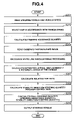
- FIG. 4 is an operational flowchart representing a steering control procedure executed in the preferred embodiment of the steering control apparatus according to the present invention.
- FIG. 5 is a view of a yaw rate signal before a relative yaw rate control executed in the preferred embodiment of the steering control apparatus shown in FIG. 1 .
- FIG. 6 is a view of a relative yaw rate signal through an image processing before the relative yaw rate control in the preferred embodiment of the steering control apparatus shown in FIG. 1 .
- FIG. 7 is a view of the yaw rate signal after the relative yaw rate control in the preferred embodiment of the steering control apparatus shown in FIG. 1 .
- FIG. 8 is a view of the relative yaw rate signal through the image processing after the yaw rate control in the preferred embodiment of the steering control apparatus shown in FIG. 1 .
- FIG. 1 is a system configuration view of a power steering system of an automotive vehicle to which a preferred embodiment of a steering control apparatus according to the present invention is applicable.
- a reference numeral 1 denotes a steering wheel
- a reference numeral 2 denotes a steering shaft
- a reference numeral 3 denotes a rack-and-pinion gear mechanism
- a reference numeral 5 denotes a power steering mechanism which assists a steering force exerted by a vehicle driver
- a reference numeral 6 denotes an electrically driven motor
- reference numerals 7 denote wheels
- a reference numeral 10 denotes a control unit (or controller) to mainly control power steering mechanism 5 .
- Power steering mechanism 5 transmits a revolution of electric motor 6 to a speed-reduction mechanism installed on a steering shaft 2 .
- the torque sensor 12 is installed to detect a steering torque exerted by the driver.
- Control unit 10 receives a steering torque signal from torque sensor 12 , a vehicle speed signal from a vehicle speed sensor 13 , and photographed images from a CCD camera 14 .
- Control unit 10 outputs a command signal to electrically driven motor 6 on the basis of these inputted signals.
- FIG. 2 shows a block diagram representing a functional structure within control unit 10 shown in FIG. 1 .
- a numeral 101 denotes a steering assistance control section which calculates a steering assistance quantity on the basis of the inputted torque signal and vehicle speed signal.
- a reference numeral 102 denotes a lateral displacement detecting section that detects a lateral displacement Y between an estimated position of the vehicle at a distance L predetermined ahead of the vehicle and a target object (for example, a white line).
- a relative yaw rate controlling section 103 estimates a relative yaw rate by means of a filtering on the basis of the detected lateral displacement and calculates a stability direction steering quantity toward which the vehicle become stable on the basis of the estimated relative yaw rate signal.
- Relative yaw rate controlling section 103 includes: a differentiator 103 a which differentiates the detected lateral displacement, a pseudo differentiation filter 103 b constituted by predetermined forward distance L and the vehicle speed; and a control gain section 103 c that provides a control gain in a direction to cancel the relative yaw rate extracted by pseudo differentiation filter 103 b and outputs the stability direction steering quantity.
- a steering torque command value finally outputted to electric motor 6 is formed as a sum between the steering assistance quantity calculated by the steering assistance control section 101 and the stability direction steering quantity calculated by relative yaw rate controlling section 103 .
- FIG. 3 shows an explanatory view for explaining a theory of estimation on the relative yaw rate.
- yaw rate is a variation rate of the yaw angle
- control gain is provided from control gain section 103 c in a direction that estimated relative yaw rate ⁇ s is cancelled so that the stability direction steering quantity is determined.
- a detection ability of a yaw rate sensor mounted in a generally available vehicle is as follows: resolution>several deg/s (at least larger than 1 deg/s)
- the detection ability at the relative yaw rate estimation in the case of the present invention is as follows: resolution>0.06 deg/s
- the present invention is feasible as described above. That is to say, since the calculation is carried out on the basis of the photographed image of camera 14 , it is possible to determine the resolution according to a level of the number of pixels of the camera 14 . Especially, due to the detection from the positional information through the image, an influence due to the temperature is not at all received. Consequently, a stable detection accuracy can be secured.
- FIG. 4 shows an operational flowchart representing the control contents of the steering angle of the first preferred embodiment shown in FIG. 2 .
- control unit 10 reads steering torque and vehicle speed from torque sensor 12 and vehicle speed sensor 13 , respectively.
- control unit 10 selects a map to set a steering assistance quantity in accordance with the steering torque and the vehicle speed.
- the steering assistance quantity is calculated by control unit 10 on the basis of the map of the steering assistance quantity selected at step 202 .
- control unit 10 reads the photographed image of camera 14 .
- control unit 10 executes the recognition of the white lines on both ends of the travel path through an image processing.
- control unit 10 calculates estimated lateral displacement Y at the predetermined forward distance L.
- control unit 10 calculates the relative yaw rate on the basis of estimated lateral displacement Y, vehicle speed Vx, and predetermined forward distance L.
- control unit 10 calculates the stability direction steering quantity according to the control gain.
- control unit 10 calculates a final steering quantity as a sum of the steering assistance quantity and the stability direction steering quantity.
- control unit 10 outputs the steering torque based on a final steering quantity from electric motor 6 .
- FIG. 5 shows an absolute yaw rate signal developed on the vehicle.
- FIG. 6 shows a relative yaw rate signal calculated on the basis of an information from camera 14 .
- the yaw rate signal shown in FIG. 5 includes a signal having a low frequency band developed due to the steering by the driver.
- the relative yaw rate signal is the yaw rate signal to the white line and does not include the signal components due to the steering with the driver steered along the white line of the road so that the yaw rate signal to the white line only is detected such as the road surface external disturbance inputted due to the convex and recess of the road surface.
- Control gain section 103 c provides a gain to cancel the filtered processed yaw rate signal as shown in FIG. 6 and outputs the stability direction steering quantity.
- FIG. 7 shows the yaw rate signal developed on the vehicle after the relative yaw rate control execution.
- FIG. 8 shows the relative yaw rate signal after the execution of the relative yaw rate control.
- the steering quantity to cancel only the relative yaw rate signal with respect to the white lines (target object) from the photographed image of camera 14 is given.
- the steering quantity to cancel the yaw rate developed due to the steering by the driver is not given.
- a compatibility of improvement in the vehicular stability for the relative yaw rate variation developed due to the external disturbance can be achieved.
Landscapes
- Engineering & Computer Science (AREA)
- Chemical & Material Sciences (AREA)
- Combustion & Propulsion (AREA)
- Transportation (AREA)
- Mechanical Engineering (AREA)
- Physics & Mathematics (AREA)
- Mathematical Physics (AREA)
- Steering Control In Accordance With Driving Conditions (AREA)
- Control Of Driving Devices And Active Controlling Of Vehicle (AREA)
- Traffic Control Systems (AREA)
Abstract
Description
Y=Lψ+∫Vx·ψ·dt (1).
If a Laplace transform is carried out for above equation (1), the following equation (2) is established:
Ys=(Ls+Vx)ψ (2).
ψ′=ψs={s/(Ls+Vx)}·Ys (3).
It is noted that s denotes a Laplace transform operator (Laplace variable).
From equation (3), Ys corresponds to
resolution>several deg/s (at least larger than 1 deg/s)
resolution>0.06 deg/s
Claims (3)
Applications Claiming Priority (2)
| Application Number | Priority Date | Filing Date | Title |
|---|---|---|---|
| JP2003109065A JP4021792B2 (en) | 2003-04-14 | 2003-04-14 | Steering control device |
| JP2003-109065 | 2003-04-14 |
Publications (2)
| Publication Number | Publication Date |
|---|---|
| US20040204808A1 US20040204808A1 (en) | 2004-10-14 |
| US7447578B2 true US7447578B2 (en) | 2008-11-04 |
Family
ID=33128081
Family Applications (1)
| Application Number | Title | Priority Date | Filing Date |
|---|---|---|---|
| US10/812,915 Expired - Fee Related US7447578B2 (en) | 2003-04-14 | 2004-03-31 | Steering control apparatus and method for automotive vehicle |
Country Status (3)
| Country | Link |
|---|---|
| US (1) | US7447578B2 (en) |
| JP (1) | JP4021792B2 (en) |
| DE (1) | DE102004013140A1 (en) |
Cited By (1)
| Publication number | Priority date | Publication date | Assignee | Title |
|---|---|---|---|---|
| US20070107979A1 (en) * | 2005-11-02 | 2007-05-17 | Toyota Jidosha Kabushiki Kaisha | Vehicular steering control apparatus and control method thereof |
Families Citing this family (52)
| Publication number | Priority date | Publication date | Assignee | Title |
|---|---|---|---|---|
| JP4295138B2 (en) * | 2004-03-08 | 2009-07-15 | 株式会社日立製作所 | Steering control device |
| DE102011081412B4 (en) * | 2011-08-23 | 2020-10-29 | Robert Bosch Gmbh | Method and device for adapting a light emission from at least one headlight of a vehicle |
| US8903610B2 (en) * | 2013-03-12 | 2014-12-02 | Steering Solutions Ip Holding Corporation | System for providing assist torque based on a vehicle state |
| DE102014204461B4 (en) * | 2013-05-14 | 2018-10-31 | Ford Global Technologies, Llc | Method for improving the straight-line stability of a vehicle |
| EP2907730B1 (en) | 2014-01-29 | 2017-09-06 | Steering Solutions IP Holding Corporation | Hands on steering wheel detect |
| JP5965968B2 (en) * | 2014-11-19 | 2016-08-10 | 本田技研工業株式会社 | Electric power steering device and steering support control device |
| JP6076394B2 (en) * | 2015-04-01 | 2017-02-08 | 三菱電機株式会社 | Vehicle steering apparatus and vehicle steering control method |
| US10351159B2 (en) | 2015-05-01 | 2019-07-16 | Steering Solutions Ip Holding Corporation | Retractable steering column with a radially projecting attachment |
| US10589774B2 (en) | 2015-05-01 | 2020-03-17 | Steering Solutions Ip Holding Corporation | Counter rotation steering wheel |
| JP2016215906A (en) | 2015-05-22 | 2016-12-22 | 株式会社ジェイテクト | Steering support device |
| US9919724B2 (en) | 2015-05-29 | 2018-03-20 | Steering Solutions Ip Holding Corporation | Retractable steering column with manual retrieval |
| US10343706B2 (en) | 2015-06-11 | 2019-07-09 | Steering Solutions Ip Holding Corporation | Retractable steering column system, vehicle having the same, and method |
| US11560169B2 (en) | 2015-06-11 | 2023-01-24 | Steering Solutions Ip Holding Corporation | Retractable steering column system and method |
| DE102016110791A1 (en) | 2015-06-15 | 2016-12-15 | Steering Solutions Ip Holding Corporation | Gesture control for a retractable steering wheel |
| JP6512440B2 (en) * | 2015-06-15 | 2019-05-15 | 株式会社ジェイテクト | Steering support device |
| US10577009B2 (en) | 2015-06-16 | 2020-03-03 | Steering Solutions Ip Holding Corporation | Retractable steering column assembly and method |
| US9828016B2 (en) | 2015-06-24 | 2017-11-28 | Steering Solutions Ip Holding Corporation | Retractable steering column system, vehicle having the same, and method |
| DE102016111473A1 (en) | 2015-06-25 | 2016-12-29 | Steering Solutions Ip Holding Corporation | STATIONARY STEERING WHEEL ASSEMBLY AND METHOD |
| US20160375931A1 (en) | 2015-06-25 | 2016-12-29 | Steering Solutions Ip Holding Corporation | Rotation control system for a steering wheel and method |
| US10112639B2 (en) | 2015-06-26 | 2018-10-30 | Steering Solutions Ip Holding Corporation | Vehicle steering arrangement and method of making same |
| US9840271B2 (en) | 2015-06-29 | 2017-12-12 | Steering Solutions Ip Holding Corporation | Retractable steering column with rake limiter |
| US9849904B2 (en) | 2015-07-31 | 2017-12-26 | Steering Solutions Ip Holding Corporation | Retractable steering column with dual actuators |
| US9845106B2 (en) | 2015-08-31 | 2017-12-19 | Steering Solutions Ip Holding Corporation | Overload protection for belt drive mechanism |
| US10160472B2 (en) | 2015-10-20 | 2018-12-25 | Steering Solutions Ip Holding Corporation | Steering column with stationary hub |
| US9809155B2 (en) | 2015-10-27 | 2017-11-07 | Steering Solutions Ip Holding Corporation | Retractable steering column assembly having lever, vehicle having retractable steering column assembly, and method |
| US10029725B2 (en) | 2015-12-03 | 2018-07-24 | Steering Solutions Ip Holding Corporation | Torque feedback system for a steer-by-wire vehicle, vehicle having steering column, and method of providing feedback in vehicle |
| US10496102B2 (en) | 2016-04-11 | 2019-12-03 | Steering Solutions Ip Holding Corporation | Steering system for autonomous vehicle |
| DE102017108692B4 (en) | 2016-04-25 | 2024-09-26 | Steering Solutions Ip Holding Corporation | Control of an electric power steering system using system state predictions |
| US10351161B2 (en) | 2016-05-27 | 2019-07-16 | Steering Solutions Ip Holding Corporation | Steering column with manual retraction |
| US10421476B2 (en) | 2016-06-21 | 2019-09-24 | Steering Solutions Ip Holding Corporation | Self-locking telescope actuator of a steering column assembly |
| US10457313B2 (en) | 2016-06-28 | 2019-10-29 | Steering Solutions Ip Holding Corporation | ADAS wheel locking device |
| US10363958B2 (en) | 2016-07-26 | 2019-07-30 | Steering Solutions Ip Holding Corporation | Electric power steering mode determination and transitioning |
| US10160477B2 (en) | 2016-08-01 | 2018-12-25 | Steering Solutions Ip Holding Corporation | Electric power steering column assembly |
| US10189496B2 (en) | 2016-08-22 | 2019-01-29 | Steering Solutions Ip Holding Corporation | Steering assembly having a telescope drive lock assembly |
| US10384708B2 (en) | 2016-09-12 | 2019-08-20 | Steering Solutions Ip Holding Corporation | Intermediate shaft assembly for steer-by-wire steering system |
| US10160473B2 (en) | 2016-09-13 | 2018-12-25 | Steering Solutions Ip Holding Corporation | Steering column decoupling system |
| US10322748B2 (en) * | 2016-09-23 | 2019-06-18 | Jtekt Corporation | Motor controller and steering device |
| US10399591B2 (en) | 2016-10-03 | 2019-09-03 | Steering Solutions Ip Holding Corporation | Steering compensation with grip sensing |
| US10239552B2 (en) | 2016-10-14 | 2019-03-26 | Steering Solutions Ip Holding Corporation | Rotation control assembly for a steering column |
| US10481602B2 (en) | 2016-10-17 | 2019-11-19 | Steering Solutions Ip Holding Corporation | Sensor fusion for autonomous driving transition control |
| US10421475B2 (en) | 2016-11-15 | 2019-09-24 | Steering Solutions Ip Holding Corporation | Electric actuator mechanism for retractable steering column assembly with manual override |
| US10310605B2 (en) | 2016-11-15 | 2019-06-04 | Steering Solutions Ip Holding Corporation | Haptic feedback for steering system controls |
| US9862403B1 (en) | 2016-11-29 | 2018-01-09 | Steering Solutions Ip Holding Corporation | Manually retractable steering column assembly for autonomous vehicle |
| US10351160B2 (en) | 2016-11-30 | 2019-07-16 | Steering Solutions Ip Holding Corporation | Steering column assembly having a sensor assembly |
| US10780915B2 (en) | 2016-12-07 | 2020-09-22 | Steering Solutions Ip Holding Corporation | Vehicle steering system having a user experience based automated driving to manual driving transition system and method |
| US10370022B2 (en) | 2017-02-13 | 2019-08-06 | Steering Solutions Ip Holding Corporation | Steering column assembly for autonomous vehicle |
| US10385930B2 (en) | 2017-02-21 | 2019-08-20 | Steering Solutions Ip Holding Corporation | Ball coupling assembly for steering column assembly |
| US10046770B1 (en) * | 2017-04-10 | 2018-08-14 | GM Global Technology Operations LLC | Systems and methods for estimating a road surface friction coefficient and vehicle lateral velocity using a decoupled dynamical model |
| US10449927B2 (en) | 2017-04-13 | 2019-10-22 | Steering Solutions Ip Holding Corporation | Steering system having anti-theft capabilities |
| US10996673B1 (en) * | 2017-09-28 | 2021-05-04 | Apple Inc. | Manual override |
| US10875566B2 (en) | 2018-03-22 | 2020-12-29 | Steering Solutions Ip Holding Corporation | Stow release assembly for a manually adjustable steering column assembly |
| US10974756B2 (en) | 2018-07-31 | 2021-04-13 | Steering Solutions Ip Holding Corporation | Clutch device latching system and method |
Citations (11)
| Publication number | Priority date | Publication date | Assignee | Title |
|---|---|---|---|---|
| JPH11147483A (en) | 1997-11-18 | 1999-06-02 | Honda Motor Co Ltd | Steering unit for vehicle |
| US20010016793A1 (en) * | 2000-01-19 | 2001-08-23 | Katsuya Ikemoto | Electric power steering apparatus |
| JP2002120744A (en) | 2000-10-18 | 2002-04-23 | Nissan Motor Co Ltd | Lane keep assist control device |
| US20020095246A1 (en) | 2001-01-18 | 2002-07-18 | Nissan Motor Co., Ltd. | Lane tracking control system for vehicle |
| JP2002302058A (en) | 2001-04-06 | 2002-10-15 | Mitsubishi Motors Corp | Steering control device |
| US20030045983A1 (en) * | 2001-09-04 | 2003-03-06 | Honda Giken Kogyo Kabushiki Kaisha | Steering control apparatus for a vehicle |
| JP2003081123A (en) | 2001-09-11 | 2003-03-19 | Nissan Motor Co Ltd | Steering control device for vehicle |
| EP1298021A1 (en) | 2001-09-28 | 2003-04-02 | Nissan Motor Company, Limited | Lane-keep control system for vehicle |
| US20040107035A1 (en) * | 2002-11-28 | 2004-06-03 | Nissan Motor Co., Ltd. | System and method for preventing lane deviation of vehicle |
| US20040153228A1 (en) * | 2003-01-31 | 2004-08-05 | Nissan Motor Co., Ltd. | Vehicle dynamics control apparatus |
| US20050182539A1 (en) * | 2002-04-30 | 2005-08-18 | Alexander Maass | Method and device for informing a driver or for reacting when the vehicle leaves a lane |
-
2003
- 2003-04-14 JP JP2003109065A patent/JP4021792B2/en not_active Expired - Fee Related
-
2004
- 2004-03-17 DE DE102004013140A patent/DE102004013140A1/en not_active Ceased
- 2004-03-31 US US10/812,915 patent/US7447578B2/en not_active Expired - Fee Related
Patent Citations (14)
| Publication number | Priority date | Publication date | Assignee | Title |
|---|---|---|---|---|
| US6112845A (en) | 1997-11-18 | 2000-09-05 | Honda Giken Kogyo Kabushiki Kaisha | Reactive steering control system |
| JPH11147483A (en) | 1997-11-18 | 1999-06-02 | Honda Motor Co Ltd | Steering unit for vehicle |
| US20010016793A1 (en) * | 2000-01-19 | 2001-08-23 | Katsuya Ikemoto | Electric power steering apparatus |
| JP2002120744A (en) | 2000-10-18 | 2002-04-23 | Nissan Motor Co Ltd | Lane keep assist control device |
| US6748302B2 (en) | 2001-01-18 | 2004-06-08 | Nissan Motor Co., Ltd. | Lane tracking control system for vehicle |
| US20020095246A1 (en) | 2001-01-18 | 2002-07-18 | Nissan Motor Co., Ltd. | Lane tracking control system for vehicle |
| JP2002211428A (en) | 2001-01-18 | 2002-07-31 | Nissan Motor Co Ltd | Lane follow-up controller |
| JP2002302058A (en) | 2001-04-06 | 2002-10-15 | Mitsubishi Motors Corp | Steering control device |
| US20030045983A1 (en) * | 2001-09-04 | 2003-03-06 | Honda Giken Kogyo Kabushiki Kaisha | Steering control apparatus for a vehicle |
| JP2003081123A (en) | 2001-09-11 | 2003-03-19 | Nissan Motor Co Ltd | Steering control device for vehicle |
| EP1298021A1 (en) | 2001-09-28 | 2003-04-02 | Nissan Motor Company, Limited | Lane-keep control system for vehicle |
| US20050182539A1 (en) * | 2002-04-30 | 2005-08-18 | Alexander Maass | Method and device for informing a driver or for reacting when the vehicle leaves a lane |
| US20040107035A1 (en) * | 2002-11-28 | 2004-06-03 | Nissan Motor Co., Ltd. | System and method for preventing lane deviation of vehicle |
| US20040153228A1 (en) * | 2003-01-31 | 2004-08-05 | Nissan Motor Co., Ltd. | Vehicle dynamics control apparatus |
Cited By (4)
| Publication number | Priority date | Publication date | Assignee | Title |
|---|---|---|---|---|
| US20070107979A1 (en) * | 2005-11-02 | 2007-05-17 | Toyota Jidosha Kabushiki Kaisha | Vehicular steering control apparatus and control method thereof |
| US7530423B2 (en) * | 2005-11-02 | 2009-05-12 | Toyota Jidosha Kabushiki Kaisha | Vehicular variable steering ratio control device and control method thereof |
| US20090198417A1 (en) * | 2005-11-02 | 2009-08-06 | Toyota Jidosha Kabushiki Kaisha | Vehicular steering control apparatus and control method thereof |
| US7711465B2 (en) | 2005-11-02 | 2010-05-04 | Toyota Jidosha Kabushiki Kaisha | Vehicular steering control apparatus and control method thereof |
Also Published As
| Publication number | Publication date |
|---|---|
| JP2004314715A (en) | 2004-11-11 |
| US20040204808A1 (en) | 2004-10-14 |
| JP4021792B2 (en) | 2007-12-12 |
| DE102004013140A1 (en) | 2004-11-18 |
Similar Documents
| Publication | Publication Date | Title |
|---|---|---|
| US7447578B2 (en) | Steering control apparatus and method for automotive vehicle | |
| US10649454B2 (en) | Autonomous vehicle | |
| CN109421709B (en) | Driving support device for vehicle | |
| EP2135789B1 (en) | Traveling safety device of vehicle | |
| US8805604B2 (en) | Method for adjusting a steering system in a vehicle | |
| EP1954546B1 (en) | Driving assistance system and driving assistance method | |
| US20180201307A1 (en) | Driver assistance system for vehicle | |
| US6134509A (en) | Road curvature estimating apparatus | |
| US9308938B2 (en) | Vehicle power steering control apparatus | |
| US6263270B1 (en) | Vehicle steering control apparatus | |
| JP2003205807A (en) | Parking support device | |
| US11718341B2 (en) | Vehicle driver assistance system | |
| JP6581627B2 (en) | Vehicle steering control device | |
| CN112334378B (en) | Steering control device, steering control method, and steering control system | |
| JPH11198844A (en) | Steering effort controller | |
| JP2006236238A (en) | Lane traveling supporting device for vehicle | |
| CN112440995A (en) | Lane departure suppression control device for vehicle | |
| JP4692403B2 (en) | Vehicle steering device | |
| EP2050657B1 (en) | Steering support device | |
| JP4483117B2 (en) | Steering control device | |
| EP3730372A1 (en) | Vehicle control device | |
| JP4696539B2 (en) | Vehicle travel support device | |
| JP7461268B2 (en) | Vehicle self-diagnosis device | |
| JP2001171544A (en) | Detector or detecting shift of optical axis for on-vehicle camera | |
| JP4228875B2 (en) | Vehicle lane travel support device |
Legal Events
| Date | Code | Title | Description |
|---|---|---|---|
| AS | Assignment |
Owner name: UNISIA JKC STEERING SYSTEMS CO., LTD., JAPAN Free format text: ASSIGNMENT OF ASSIGNORS INTEREST;ASSIGNORS:SATOH, HIROSHI;WATANABE, MASAKI;REEL/FRAME:015173/0363 Effective date: 20040217 |
|
| FEPP | Fee payment procedure |
Free format text: PAYOR NUMBER ASSIGNED (ORIGINAL EVENT CODE: ASPN); ENTITY STATUS OF PATENT OWNER: LARGE ENTITY |
|
| FPAY | Fee payment |
Year of fee payment: 4 |
|
| AS | Assignment |
Owner name: HITACHI AUTOMOTIVE SYSTEMS STEERING, LTD., JAPAN Free format text: CHANGE OF NAME;ASSIGNOR:UNISIA JKC STEERING SYSTEMS CO., LTD.;REEL/FRAME:028652/0209 Effective date: 20120401 Owner name: UNISIA JKC STEERING SYSTEMS CO., LTD., JAPAN Free format text: CHANGE OF ADDRESS;ASSIGNOR:UNISIA JKC STEERING SYSTEMS CO., LTD.;REEL/FRAME:028651/0971 Effective date: 20100401 |
|
| REMI | Maintenance fee reminder mailed | ||
| LAPS | Lapse for failure to pay maintenance fees | ||
| STCH | Information on status: patent discontinuation |
Free format text: PATENT EXPIRED DUE TO NONPAYMENT OF MAINTENANCE FEES UNDER 37 CFR 1.362 |
|
| FP | Lapsed due to failure to pay maintenance fee |
Effective date: 20161104 |