EP3364003B1 - Motorpeilstab - Google Patents
Motorpeilstab Download PDFInfo
- Publication number
- EP3364003B1 EP3364003B1 EP18155414.8A EP18155414A EP3364003B1 EP 3364003 B1 EP3364003 B1 EP 3364003B1 EP 18155414 A EP18155414 A EP 18155414A EP 3364003 B1 EP3364003 B1 EP 3364003B1
- Authority
- EP
- European Patent Office
- Prior art keywords
- dipstick
- engine
- free end
- engine casing
- casing
- Prior art date
- Legal status (The legal status is an assumption and is not a legal conclusion. Google has not performed a legal analysis and makes no representation as to the accuracy of the status listed.)
- Active
Links
Images

Classifications
-
- F—MECHANICAL ENGINEERING; LIGHTING; HEATING; WEAPONS; BLASTING
- F01—MACHINES OR ENGINES IN GENERAL; ENGINE PLANTS IN GENERAL; STEAM ENGINES
- F01M—LUBRICATING OF MACHINES OR ENGINES IN GENERAL; LUBRICATING INTERNAL COMBUSTION ENGINES; CRANKCASE VENTILATING
- F01M11/00—Component parts, details or accessories, not provided for in, or of interest apart from, groups F01M1/00 - F01M9/00
- F01M11/10—Indicating devices; Other safety devices
- F01M11/12—Indicating devices; Other safety devices concerning lubricant level
-
- F—MECHANICAL ENGINEERING; LIGHTING; HEATING; WEAPONS; BLASTING
- F01—MACHINES OR ENGINES IN GENERAL; ENGINE PLANTS IN GENERAL; STEAM ENGINES
- F01M—LUBRICATING OF MACHINES OR ENGINES IN GENERAL; LUBRICATING INTERNAL COMBUSTION ENGINES; CRANKCASE VENTILATING
- F01M11/00—Component parts, details or accessories, not provided for in, or of interest apart from, groups F01M1/00 - F01M9/00
- F01M11/0004—Oilsumps
-
- G—PHYSICS
- G01—MEASURING; TESTING
- G01F—MEASURING VOLUME, VOLUME FLOW, MASS FLOW OR LIQUID LEVEL; METERING BY VOLUME
- G01F23/00—Indicating or measuring liquid level or level of fluent solid material, e.g. indicating in terms of volume or indicating by means of an alarm
- G01F23/04—Indicating or measuring liquid level or level of fluent solid material, e.g. indicating in terms of volume or indicating by means of an alarm by dip members, e.g. dip-sticks
-
- F—MECHANICAL ENGINEERING; LIGHTING; HEATING; WEAPONS; BLASTING
- F01—MACHINES OR ENGINES IN GENERAL; ENGINE PLANTS IN GENERAL; STEAM ENGINES
- F01M—LUBRICATING OF MACHINES OR ENGINES IN GENERAL; LUBRICATING INTERNAL COMBUSTION ENGINES; CRANKCASE VENTILATING
- F01M11/00—Component parts, details or accessories, not provided for in, or of interest apart from, groups F01M1/00 - F01M9/00
- F01M11/0004—Oilsumps
- F01M2011/0008—Oilsumps with means for reducing vibrations
Definitions
- This disclosure relates to an engine dipstick, and in particular, but not exclusively, relates to reducing noise, vibration and harshness issues associated with a dipstick installed to an engine casing.
- a dipstick when installed to an engine, it extends through an opening provided towards the top of the engine, and through one or more portions of engine casing.
- the dipstick may extend through a cam cover, a cylinder head, a cylinder block, and into a ladderframe casing, so that a free end of the dipstick is positioned in the oil contained in an oil pan at the bottom of the engine
- the dipstick As a result of the required characteristics of the dipstick, such as its material properties and its elongated shape, it is particularly prone to bending and vibration.
- NSH potential noise vibration and harshness
- a portion of the dipstick may be free to vibrate, and possibly even resonate, during engine operation.
- the free end of the dipstick may vibrate and contact an interior wall of the oil pan, which can lead to a harsh rattling noise during operation of the engine.
- 2032518 provides an internal combustion engine with stiffening side wall ribs which are lightened by the provision therein of passages that alternatively co-operate with cylinder head passages to provide oil drains from the valve chambers to the oil sump or provide a mounting for a dip-stick, the mounting including an angled uniplanar passage in the cylinder block wall aligned with a cylinder head boss and a guide member mounted in the oil sump.
- an engine comprising an engine casing and a dipstick, the dipstick having a free end that extends into the engine casing when the dipstick is installed to the engine casing, wherein at least one of the dipstick and the engine casing is adapted to ensure that the lowest natural frequency of the free end of the dipstick is above the highest operational frequency of the engine, when the dipstick is installed to the engine casing.
- At least one of the shape, configuration, material and mass distribution of the free end of the dipstick may be adapted so that the lowest natural frequency of the free end of the dipstick is above the highest operational frequency of the engine.
- At least one of the shape, configuration, material and mass distribution of the engine casing may be adapted so that the lowest natural frequency of the free end of the dipstick is above the highest operational frequency of the engine.
- the engine casing may comprise an opening, e.g. a through hole or a recess, configured to receive the dipstick.
- the opening may comprise a wall configured to engage the dipstick.
- the dipstick and the wall of the opening may cooperate to define the free end of the dipstick that extends into the engine casing. Operation of the engine may cause the free end of the dipstick to vibrate, for example at one or more particular operational frequencies of the engine.
- the cooperation between the wall of the opening and the dipstick may ensure that the free end of the dipstick is unable to resonate during operation of the engine, for example by defining the length of the free end of the dipstick that extends into the engine.
- the engine casing may comprise a first projection, e.g. an engine projection, configured to engage the dipstick.
- the first projection may be an edge of a sloped wall of the opening, or the apex of a curved surface of the opening.
- the first projection may comprise a protuberance, e.g. a ridge, bump or nodule, configured to engage the dipstick when the dipstick is installed to the engine casing.
- the first projection may be positioned on the engine casing so as to determine the length of the free end of the dipstick when the dipstick is installed to the engine casing.
- the first projection may be configured to deflect the free end of the dipstick away from an interior wall of the engine casing when the dipstick is installed to the engine casing.
- the first projection may be configured to deflect the free end of the dipstick away from an interior wall of the oil pan. The deflection of the dipstick caused by the first projection may be sufficient to prevent the free end of the dipstick from contacting the interior wall of the engine casing.
- the first projection may be formed integral to the engine casing.
- the first projection may be a feature formed during manufacture, e.g. casting, of the engine casing.
- the first projection may be formed separately from the engine casing and subsequently assembled to the engine casing.
- the dipstick may comprise a second projection, e.g. a dipstick projection, configured to engage the engine casing.
- the second projection may be a protuberance from the surface of the dipstick, and/or may be formed as a result of the curvature of the dipstick.
- the second projection may be positioned on the dipstick so as to determine the length of the free end of the dipstick when the dipstick is installed to the engine casing.
- the first and second projections may cooperate to determine the length of the free end of the dipstick when the dipstick is installed to the engine casing.
- the second projection may be configured to deflect the free end of the dipstick away from an interior wall of the engine casing when the dipstick is installed to the engine casing. The deflection of the dipstick caused by the second projection may be sufficient to prevent the free end of the dipstick from contacting the interior wall of the engine casing.
- the second projection may be formed integral to the dipstick.
- the second projection may be a feature formed during manufacture of the dipstick.
- the second projection may be formed separately from the dipstick and subsequently assembled to the dipstick.
- the dipstick may be configured such that the second moment of area of the free end of the dipstick is selected, e.g. designed, to ensure that lowest natural frequency of the free end of the dipstick is above the highest operational frequency of the engine.
- the dipstick may be configured to have a non-uniform cross section that influences the natural frequency of the free end of the dipstick.
- the dipstick may be configured such that the modulus of elasticity of the free end of the dipstick is selected to ensure that lowest natural frequency of the free end of the dipstick is above the highest operational frequency of the engine.
- the dipstick may be configured to have a modulus of elasticity that influences the natural frequency of the free end of the dipstick.
- the free end of the dipstick may be manufactured from a different material from the remaining portion of the dipstick.
- the dipstick may comprise a mass, e.g. a body of material, provided towards the free end of the dipstick. At least one of the position of the mass and a material of the mass may be selected to ensure that lowest natural frequency of the free end of the dipstick is above the highest operational frequency of the engine.
- the mass may be a feature formed during manufacture of the dipstick. The mass may be formed separately from the dipstick and subsequently assembled to the dipstick.
- the engine casing may be formed from at least one of a cam cover, a cylinder head, a cylinder block, a ladderframe casing and an oil pan.
- the opening may be an opening in a ladderframe casing, e.g. a casing portion configured to support a balancer shaft assembly of the engine.
- an engine comprising an engine casing and a dipstick, the dipstick having a free end that extends into the engine casing when the dipstick is installed to the engine casing, wherein at least one of the engine casing and the dipstick has a projection configured to deflect the free end of the dipstick away from an interior wall of the engine casing proximate to where the free end terminates.
- the projection may be configured to deflect the dipstick away from the interior wall of the engine casing by an amount sufficient to prevent contact between the free end of the dipstick and the interior wall when the dipstick resonates.
- a vehicle may be provided comprising one or more of the above mentioned engines.
- a method of designing an engine comprising an engine casing and a dipstick, the dipstick having a free end that extends into the engine casing when the dipstick is installed to the engine casing, the method comprising: adapting at least one of the dipstick and the engine casing so that the lowest natural frequency of the free end of the dipstick is above the highest operational frequency of the engine, when the dipstick is installed to the engine.
- the step of adapting the dipstick may comprise selecting at least one of the shape, configuration and mass distribution of the free end of the dipstick.
- the engine casing may comprise an opening configured to receive the dipstick.
- the step of adapting the engine casing may comprise selecting at least one of the shape and the configuration of the opening.
- the present disclosure provides an engine 101 comprising an engine casing 103 and a dipstick 105.
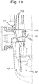
- Figures 1a and 1b show cross sections through the engine 101 in an assembled configuration.
- the engine casing 103 comprises a plurality of casing portions, such as a cam cover 107, a cylinder head 109, a cylinder block 111, a ladderframe casing 113 and an oil pan 115.
- the engine casing 103 may comprise any appropriate number and/or type of casing portions depending on the configuration of the engine.
- Each of the casing portions is provided with an opening 117 configured to receive a dipstick 105, the openings 117 being aligned to form a channel 119 that extends through the engine casing 103.
- the dipstick 105 when the dipstick 105 is inserted into the top of the engine casing 103, it can extend down through the engine casing 103 such that a free end 121 of the dipstick 105 terminates in the oil pan 115 and the dipstick 105 can measure the level of oil in the oil pan 115.
- the channel 119 extends in a vertical direction through the engine casing 103. However, in one or more other arrangements (not shown), the channel 119 may extend in any appropriate direction(s) that allow the dipstick 105 to be inserted into the engine casing 103.
- the engine casing 103 is configured such that the channel 119 formed by the openings 117 acts to deform, e.g. bend, the dipstick 105 as the dipstick 105 is inserted through the channel.
- the channel 119 in the engine casing 103 of figure 1 a is formed such that the curvature of channel 119 through the engine casing 103, e.g. in the vertical direction through the engine casing 103, is greater than the longitudinal curvature of the dipstick 105 in an uninstalled state.
- the channel 119 is configured to constrain the dipstick 105 at one or more points where a wall of the channel 119 engages the dipstick 105.
- the dipstick is usually constrained at two or more points along the channel, for example at a portion of the channel formed in the cam cover and at a portion of the channel formed in the cylinder block.
- the free end of the dipstick may vibrate during operation of the engine, as a result of how the dipstick is constrained.
- the free end of the dipstick may resonate at one or more operational frequencies of the engine, which causes unwanted noise vibration and harshness (NVH) issues, for example by virtue of contact of the free end of the dipstick with an interior wall of the oil pan of the engine casing.
- NSH noise vibration and harshness
- the engine 101 is configured to prevent unwanted NVH issues associated with the vibration of the dipstick 105, for example when the dipstick 105 resonates at one or more operational frequencies of the engine 101. This is achieved by configuring the engine casing 103 and/or the dipstick 105 such that they cooperate to ensure that the lowest natural frequency of the free end 121 of the dipstick 105 is above the highest operational frequency of the engine 101.
- the channel 119 is configured to constrain the dipstick 105 in a manner that ensures the free end 121 of the dipstick 105 is sufficiently short to avoid the lowest natural frequency of the unconstrained/free end 121 of the dipstick 105 from coinciding with an operational frequency of the engine 101.
- the engine casing 103 and the dipstick 105 may be configured in any appropriate manner that tunes the dipstick 105 such that dipstick 105 does not resonate during operation of the engine 101.
- the shape/form of the dipstick 105 may be selected to determine that the free end 121 of the dipstick 105 has a suitable second moment of area to avoid the dipstick 105 from resonating during operation of the engine 101.
- the material from which the dipstick 105, or at least the free end 121 of the dipstick 105, is fabricated has a modulus of elasticity selected to avoid the dipstick 105 from resonating during operation of the engine 101.
- the dipstick 105 may comprises a body of material provided towards the free end of the dipstick 105. The position of the body of material relative to the free end 121 of the dipstick 105, and/or the material from which the body is fabricated, may be selected to ensure that lowest natural frequency of the free end 121 of the dipstick 105 is above the highest operational frequency of the engine 101.
- the present disclosure provides an engine 101 in which at least one feature of the engine casing 103, such as the shape of an opening 117 through which the dipstick 105 passes, is selected in combination with or independently from at least one feature of the dipstick 105 itself, such as the form of the dipstick 105, to ensure that the dipstick 105 does not resonate during the operation of the engine 101.
- a wall 125 of the opening 117a in the ladderframe casing 113 is configured to engage and guide the dipstick 105 as the dipstick 105 is inserted into the engine casing 103.
- the wall 125 may comprise a sloped surface that engages the dipstick 105 to guide the free end 121 of the dipstick 105 away from an interior wall 127 of the oil pan 115 as the dipstick 105 is inserted into the oil pan 115. In this manner, the dipstick 105 cooperates with the wall 125 of the opening 117a to define the unconstrained/free end 121 of the dipstick 105.
- the opening 117a in the ladderframe casing 113 comprises a through hole configured to allow the dipstick 105 to pass through a wall of the ladderframe casing 113 that engages the cylinder block 109.
- the opening 117 may be of any appropriate form that permits the dipstick 105 to pass through the component in which the opening 117 is formed.
- the opening 117a may comprise a recessed, e.g. scalloped, portion of a wall, e.g. a peripheral wall, of the engine casing 103.
- the opening 117 in the engine casing 103 may form an open channel and/or a closed channel through the engine casing 103.
- the sloped surface of the opening 117a urges the dipstick 105 away from the interior wall 127 of the oil pan 113.
- the opening 117a may comprise any appropriate feature configured to deflect the free end 121 of the dipstick 105 away from the interior wall 127.
- the opening 117a may comprise a projection, e.g. a ridge or any protuberance, configured to engage and deflect the dipstick 105.
- the dipstick 105 may comprise a projection, e.g. a ridge or bend in the dipstick 105, configured to engage the engine casing 103 when the dipstick 105 is installed to the engine 101.
- the present disclosure provides an engine casing 103 and dipstick 105 assembly configured to prevent the free end 121 of the dipstick 105 from contacting an interior wall of the engine casing during operation of the engine 101.
Landscapes
- Engineering & Computer Science (AREA)
- Mechanical Engineering (AREA)
- General Engineering & Computer Science (AREA)
- Physics & Mathematics (AREA)
- Fluid Mechanics (AREA)
- General Physics & Mathematics (AREA)
- Lubrication Details And Ventilation Of Internal Combustion Engines (AREA)
- Cylinder Crankcases Of Internal Combustion Engines (AREA)
Claims (14)
- Motor (101), umfassend ein Motorgehäuse (103) und einen Messstab (105), wobei der Messstab (105) ein freies Ende (121) aufweist, das sich in das Motorgehäuse (103) erstreckt, wenn der Messstab (105) an dem Motorgehäuse (103) installiert ist, dadurch gekennzeichnet, dass mindestens eines von dem Motorgehäuse (103) und dem Messstab (105) angepasst ist, um sicherzustellen, dass die niedrigste Eigenfrequenz des freien Endes (121) des Messstabs (105) über der höchsten Betriebsfrequenz des Motors (101) ist.
- Motor (101) gemäß Anspruch 1, wobei das Motorgehäuse (103) eine Öffnung (117) umfasst, die konfiguriert ist, um den Messstab (105) aufzunehmen, wobei der Messstab (105) mit einer Wand (125) der Öffnung (117) zusammenwirkt, um das freie Ende (121) des Messstabs (105) zu definieren, das sich in das Motorgehäuse (103) erstreckt.
- Motor (101) gemäß Anspruch 1 oder 2, wobei das Motorgehäuse (103) einen ersten Vorsprung umfasst, der konfiguriert ist, um den Messstab (105) einzugreifen, wobei der erste Vorsprung an dem Motorgehäuse (103) positioniert ist, um die Länge des freien Endes (121) des Messstabs (105) zu bestimmen, wenn der Messstab (105) an dem Motorgehäuse (103) installiert ist.
- Motor (101) gemäß Anspruch 3, wobei der erste Vorsprung konfiguriert ist, um das freie Ende (121) des Messstabs (105) weg von einer Innenwand des Motorgehäuses (103) abzulenken, wenn der Messstab (105) an dem Motorgehäuse (103) installiert ist.
- Motor (101) gemäß einem der vorherigen Ansprüche, wobei der Messstab (105) einen zweiten Vorsprung aufweist, der konfiguriert ist, um das Motorgehäuse (103) einzugreifen, wobei der zweite Vorsprung an dem Messstab (105) so positioniert ist, um die Länge des freien Endes (121) des Messstabs (105) zu bestimmen, wenn der Messstab (105) an dem Motorgehäuse (103) installiert ist.
- Motor (101) gemäß Anspruch 5, wobei der zweite Vorsprung konfiguriert ist, um das freie Ende (121) des Messstabs (105) weg von einer Innenwand des Motorgehäuses (103) abzulenken, wenn der Messstab (105) an dem Motorgehäuse (103) installiert ist.
- Motor (101) gemäß einem der vorherigen Ansprüche, wobei das freie Ende (121) des Messstabs (105) angepasst ist, um ein zweites Flächenmoment aufzuweisen, das sicherstellt, dass die niedrigste Eigenfrequenz des freien Endes (121) des Messstabs (105) über der höchsten Betriebsfrequenz des Motors (101) ist.
- Motor (101) gemäß einem der vorherigen Ansprüche, wobei das freie Ende (121) des Messstabs (105) angepasst ist, um ein Elastizitätsmodul aufzuweisen, das sicherstellt, dass die niedrigste Eigenfrequenz des freien Endes (121) des Messstabs (105) über der höchsten Betriebsfrequenz des Motors (101) ist.
- Motor (101) gemäß einem der vorherigen Ansprüche, der Messstab (105) umfassend eine Masse, die in Richtung des freien Endes (121) des Messstabs (105) bereitgestellt ist, wobei mindestens eines von der Position der Masse und einem Material der Masse gewählt ist, dass sichergestellt ist, dass die niedrigste Eigenfrequenz des freien Endes (121) des Messstabs (105) über der höchsten Betriebsfrequenz des Motors (101) ist, wenn die Masse an dem Messstab (105) angebracht ist.
- Motor (101) gemäß einem der vorherigen Ansprüche, wobei das Motorgehäuse (103) ein Leiterrahmengehäuse (113) ist.
- Fahrzeug, umfassend den Motor (101) gemäß einem der Ansprüche 1 bis 10.
- Verfahren zum Konstruieren eines Motors (101), umfassend ein Motorgehäuse (103) und einen Messstab (105), wobei der Messstab (105) ein freies Ende (121) aufweist, das sich in das Motorgehäuse erstreckt, wenn der Messstab (105) an dem Motorgehäuse (103) installiert ist, wobei das Verfahren durch Folgendes gekennzeichnet ist: einen Schritt zum Anpassen von mindestens einem von dem Motorgehäuse (103) und dem Messstab (105), sodass die niedrigste Eigenfrequenz des freien Endes (121) des Messstabs (105) über der höchsten Betriebsfrequenz des Motors (101) ist.
- Verfahren gemäß Anspruch 12, wobei der Schritt eines Anpassens des Messstabs (105) ein Auswählen von mindestens einem von der Form, Konfiguration und Massenverteilung des freien Endes (121) des Messstabs (105) umfasst, sodass die niedrigste Eigenfrequenz des freien Endes (121) des Messstabs (105) über der höchsten Betriebsfrequenz des Motors (101) ist.
- Verfahren gemäß Anspruch 12 oder 13, das Motorgehäuse (103) umfassend eine Öffnung (117), die konfiguriert ist, um den Ölmessstab (105) aufzunehmen, wobei der Schritt eines Anpassens des Motorgehäuses (103) ein Auswählen von mindestens einem von der Form und der Konfiguration der Öffnung (117) umfasst.
Applications Claiming Priority (1)
| Application Number | Priority Date | Filing Date | Title |
|---|---|---|---|
| GB1702629.5A GB2559777B (en) | 2017-02-17 | 2017-02-17 | An engine comprising an engine casing and a dipstick |
Publications (2)
| Publication Number | Publication Date |
|---|---|
| EP3364003A1 EP3364003A1 (de) | 2018-08-22 |
| EP3364003B1 true EP3364003B1 (de) | 2021-08-25 |
Family
ID=58486836
Family Applications (1)
| Application Number | Title | Priority Date | Filing Date |
|---|---|---|---|
| EP18155414.8A Active EP3364003B1 (de) | 2017-02-17 | 2018-02-06 | Motorpeilstab |
Country Status (6)
| Country | Link |
|---|---|
| US (1) | US10648378B2 (de) |
| EP (1) | EP3364003B1 (de) |
| CN (1) | CN108457717B (de) |
| GB (1) | GB2559777B (de) |
| MX (1) | MX2018001879A (de) |
| RU (1) | RU2018102574A (de) |
Families Citing this family (5)
| Publication number | Priority date | Publication date | Assignee | Title |
|---|---|---|---|---|
| US10690027B2 (en) * | 2018-05-21 | 2020-06-23 | Ford Global Technologies, Llc | Attachment arrangement between rolling and rigid components in a vehicle engine bay |
| JP7244194B2 (ja) * | 2019-03-28 | 2023-03-22 | ダイハツ工業株式会社 | 内燃機関 |
| JP6971335B2 (ja) * | 2020-01-06 | 2021-11-24 | 本田技研工業株式会社 | オイルレベルゲージ案内装置 |
| JP7427334B2 (ja) | 2020-03-23 | 2024-02-05 | ダイハツ工業株式会社 | オイルレベルゲージの構造 |
| US11988118B2 (en) | 2022-08-04 | 2024-05-21 | Lombardini S.R.L. | Self-cleaning dipstick assembly |
Family Cites Families (21)
| Publication number | Priority date | Publication date | Assignee | Title |
|---|---|---|---|---|
| GB734540A (en) * | 1952-09-25 | 1955-08-03 | Cooper S Mechanical Joints Ltd | A dip-stick and air filter assembly for an engine crankcase or the like |
| US4213441A (en) * | 1978-10-16 | 1980-07-22 | General Motors Corporation | Engine with wall rib oil gauge mounting and drain means |
| JPS56145617U (de) * | 1980-04-02 | 1981-11-02 | ||
| JP3179959B2 (ja) * | 1994-03-23 | 2001-06-25 | スズキ株式会社 | 液面検知装置および液面検出装置 |
| JPH09195747A (ja) * | 1996-01-19 | 1997-07-29 | Daihatsu Motor Co Ltd | オイルレベルゲージのガイド装置 |
| DE10339364A1 (de) * | 2003-08-27 | 2005-03-24 | Fev Motorentechnik Gmbh | Brennkraftmaschine |
| US6928974B1 (en) | 2004-01-30 | 2005-08-16 | Demetrios Markou | Reinforcement plate for a reciprocating engine |
| JP4610917B2 (ja) | 2004-03-25 | 2011-01-12 | 本田技研工業株式会社 | オイルレベルゲージ装置 |
| JP2006275039A (ja) | 2005-03-02 | 2006-10-12 | Toyota Motor Corp | 潤滑装置 |
| FR2889720B1 (fr) * | 2005-08-10 | 2010-12-31 | Renault Sas | Jauge de controle de niveau d'huile pour moteur de vehicule |
| JP2007211593A (ja) | 2006-02-07 | 2007-08-23 | Toyota Motor Corp | 潤滑装置 |
| JP4981642B2 (ja) * | 2007-12-10 | 2012-07-25 | 三菱重工業株式会社 | オイルパン構造及びこれを備えたエンジン |
| KR20100023262A (ko) * | 2008-08-21 | 2010-03-04 | 현대자동차주식회사 | 마그네슘 오일 팬 |
| DE102010011492A1 (de) * | 2010-03-16 | 2012-05-10 | Hella Kgaa Hueck & Co. | Vorrichtung zur Bestimmung eines Füllstandes |
| JP5610372B2 (ja) | 2010-11-15 | 2014-10-22 | スズキ株式会社 | エンジンの油面検出装置 |
| KR101337817B1 (ko) * | 2012-11-29 | 2013-12-06 | 쌍용자동차 주식회사 | 자동차용 엔진의 타이밍기어 케이스 커버 |
| CN103147875B (zh) * | 2013-02-28 | 2015-09-23 | 奇瑞汽车股份有限公司 | 正时链轮罩盖 |
| JP5792775B2 (ja) | 2013-08-09 | 2015-10-14 | 本田技研工業株式会社 | 内燃機関のケース部材 |
| JP6134242B2 (ja) | 2013-09-24 | 2017-05-24 | 本田技研工業株式会社 | 内燃機関のオイルレベルゲージ用通路 |
| JP6090583B2 (ja) | 2013-11-26 | 2017-03-08 | トヨタ自動車株式会社 | オイルレベルゲージガイド |
| CN204532468U (zh) * | 2015-03-25 | 2015-08-05 | 北京福田康明斯发动机有限公司 | 发动机和发动机润滑油测量装置 |
-
2017
- 2017-02-17 GB GB1702629.5A patent/GB2559777B/en active Active
-
2018
- 2018-01-23 RU RU2018102574A patent/RU2018102574A/ru not_active Application Discontinuation
- 2018-02-06 EP EP18155414.8A patent/EP3364003B1/de active Active
- 2018-02-11 CN CN201810140928.8A patent/CN108457717B/zh active Active
- 2018-02-14 MX MX2018001879A patent/MX2018001879A/es unknown
- 2018-02-15 US US15/897,989 patent/US10648378B2/en active Active
Also Published As
| Publication number | Publication date |
|---|---|
| US10648378B2 (en) | 2020-05-12 |
| GB2559777A (en) | 2018-08-22 |
| EP3364003A1 (de) | 2018-08-22 |
| CN108457717A (zh) | 2018-08-28 |
| GB2559777B (en) | 2019-05-01 |
| US20180238206A1 (en) | 2018-08-23 |
| MX2018001879A (es) | 2018-11-09 |
| GB201702629D0 (en) | 2017-04-05 |
| CN108457717B (zh) | 2021-10-22 |
| RU2018102574A (ru) | 2019-07-30 |
Similar Documents
| Publication | Publication Date | Title |
|---|---|---|
| EP3364003A1 (de) | Motorpeilstab | |
| US7836859B2 (en) | Chain cover of internal combustion engine | |
| US20210048190A1 (en) | Fuel-burning device | |
| JP4625529B2 (ja) | 内燃機関のためのオイルパン | |
| US6874460B2 (en) | Integrated oil pan and windage tray | |
| JP2010509536A (ja) | 内燃機関のオイルパン | |
| WO2015068730A1 (ja) | マウント装置 | |
| JP6456339B2 (ja) | 防振装置 | |
| JP6456340B2 (ja) | 防振装置 | |
| CN103883423A (zh) | 盖罩的注油构造 | |
| KR102474507B1 (ko) | 씰링부 변형 저감형 엔진 오일팬 | |
| US9482186B2 (en) | Leaf spring type variable valve | |
| KR101249280B1 (ko) | 엔진, 및 엔진 조립체 | |
| MXPA05013125A (es) | Cubierta para una cabeza de cilindro de un motor de combustion interno y procedimiento para su fabricacion. | |
| US10920631B2 (en) | Head cover for internal combustion engine cylinder head | |
| US20220127890A1 (en) | Liquid sealed damper for opening and closing member | |
| JP2008025371A (ja) | 潤滑油供給構造 | |
| JPH09317434A (ja) | シリンダヘッド構造 | |
| US11773938B2 (en) | Liquid sealed damper for opening and closing member | |
| CN113911021A (zh) | 包括带有具有夹的车辆货物盖的车辆货物区域的车辆 | |
| JP6332724B2 (ja) | 車両の騒音低減構造 | |
| JP2006062633A (ja) | クッションクリップ | |
| JP2009203872A (ja) | ノックセンサの取付構造 | |
| CN216665705U (zh) | 发动机的油底壳及包括其的发动机 | |
| JP4868074B2 (ja) | オイルドレン構造 |
Legal Events
| Date | Code | Title | Description |
|---|---|---|---|
| PUAI | Public reference made under article 153(3) epc to a published international application that has entered the european phase |
Free format text: ORIGINAL CODE: 0009012 |
|
| STAA | Information on the status of an ep patent application or granted ep patent |
Free format text: STATUS: THE APPLICATION HAS BEEN PUBLISHED |
|
| AK | Designated contracting states |
Kind code of ref document: A1 Designated state(s): AL AT BE BG CH CY CZ DE DK EE ES FI FR GB GR HR HU IE IS IT LI LT LU LV MC MK MT NL NO PL PT RO RS SE SI SK SM TR |
|
| AX | Request for extension of the european patent |
Extension state: BA ME |
|
| STAA | Information on the status of an ep patent application or granted ep patent |
Free format text: STATUS: REQUEST FOR EXAMINATION WAS MADE |
|
| 17P | Request for examination filed |
Effective date: 20181008 |
|
| RBV | Designated contracting states (corrected) |
Designated state(s): AL AT BE BG CH CY CZ DE DK EE ES FI FR GB GR HR HU IE IS IT LI LT LU LV MC MK MT NL NO PL PT RO RS SE SI SK SM TR |
|
| GRAP | Despatch of communication of intention to grant a patent |
Free format text: ORIGINAL CODE: EPIDOSNIGR1 |
|
| STAA | Information on the status of an ep patent application or granted ep patent |
Free format text: STATUS: GRANT OF PATENT IS INTENDED |
|
| INTG | Intention to grant announced |
Effective date: 20210316 |
|
| RBV | Designated contracting states (corrected) |
Designated state(s): AL AT BE BG CH CY CZ DE DK EE ES FI FR GR HR HU IE IS IT LI LT LU LV MC MK MT NL NO PL PT RO RS SE SI SK SM TR |
|
| GRAS | Grant fee paid |
Free format text: ORIGINAL CODE: EPIDOSNIGR3 |
|
| GRAA | (expected) grant |
Free format text: ORIGINAL CODE: 0009210 |
|
| STAA | Information on the status of an ep patent application or granted ep patent |
Free format text: STATUS: THE PATENT HAS BEEN GRANTED |
|
| AK | Designated contracting states |
Kind code of ref document: B1 Designated state(s): AL AT BE BG CH CY CZ DE DK EE ES FI FR GR HR HU IE IS IT LI LT LU LV MC MK MT NL NO PL PT RO RS SE SI SK SM TR |
|
| REG | Reference to a national code |
Ref country code: CH Ref legal event code: EP |
|
| REG | Reference to a national code |
Ref country code: IE Ref legal event code: FG4D Ref country code: AT Ref legal event code: REF Ref document number: 1424007 Country of ref document: AT Kind code of ref document: T Effective date: 20210915 |
|
| REG | Reference to a national code |
Ref country code: DE Ref legal event code: R096 Ref document number: 602018022227 Country of ref document: DE |
|
| REG | Reference to a national code |
Ref country code: LT Ref legal event code: MG9D |
|
| REG | Reference to a national code |
Ref country code: NL Ref legal event code: MP Effective date: 20210825 |
|
| REG | Reference to a national code |
Ref country code: AT Ref legal event code: MK05 Ref document number: 1424007 Country of ref document: AT Kind code of ref document: T Effective date: 20210825 |
|
| PG25 | Lapsed in a contracting state [announced via postgrant information from national office to epo] |
Ref country code: SE Free format text: LAPSE BECAUSE OF FAILURE TO SUBMIT A TRANSLATION OF THE DESCRIPTION OR TO PAY THE FEE WITHIN THE PRESCRIBED TIME-LIMIT Effective date: 20210825 Ref country code: RS Free format text: LAPSE BECAUSE OF FAILURE TO SUBMIT A TRANSLATION OF THE DESCRIPTION OR TO PAY THE FEE WITHIN THE PRESCRIBED TIME-LIMIT Effective date: 20210825 Ref country code: HR Free format text: LAPSE BECAUSE OF FAILURE TO SUBMIT A TRANSLATION OF THE DESCRIPTION OR TO PAY THE FEE WITHIN THE PRESCRIBED TIME-LIMIT Effective date: 20210825 Ref country code: ES Free format text: LAPSE BECAUSE OF FAILURE TO SUBMIT A TRANSLATION OF THE DESCRIPTION OR TO PAY THE FEE WITHIN THE PRESCRIBED TIME-LIMIT Effective date: 20210825 Ref country code: FI Free format text: LAPSE BECAUSE OF FAILURE TO SUBMIT A TRANSLATION OF THE DESCRIPTION OR TO PAY THE FEE WITHIN THE PRESCRIBED TIME-LIMIT Effective date: 20210825 Ref country code: NO Free format text: LAPSE BECAUSE OF FAILURE TO SUBMIT A TRANSLATION OF THE DESCRIPTION OR TO PAY THE FEE WITHIN THE PRESCRIBED TIME-LIMIT Effective date: 20211125 Ref country code: PT Free format text: LAPSE BECAUSE OF FAILURE TO SUBMIT A TRANSLATION OF THE DESCRIPTION OR TO PAY THE FEE WITHIN THE PRESCRIBED TIME-LIMIT Effective date: 20211227 Ref country code: BG Free format text: LAPSE BECAUSE OF FAILURE TO SUBMIT A TRANSLATION OF THE DESCRIPTION OR TO PAY THE FEE WITHIN THE PRESCRIBED TIME-LIMIT Effective date: 20211125 Ref country code: AT Free format text: LAPSE BECAUSE OF FAILURE TO SUBMIT A TRANSLATION OF THE DESCRIPTION OR TO PAY THE FEE WITHIN THE PRESCRIBED TIME-LIMIT Effective date: 20210825 Ref country code: LT Free format text: LAPSE BECAUSE OF FAILURE TO SUBMIT A TRANSLATION OF THE DESCRIPTION OR TO PAY THE FEE WITHIN THE PRESCRIBED TIME-LIMIT Effective date: 20210825 |
|
| PG25 | Lapsed in a contracting state [announced via postgrant information from national office to epo] |
Ref country code: PL Free format text: LAPSE BECAUSE OF FAILURE TO SUBMIT A TRANSLATION OF THE DESCRIPTION OR TO PAY THE FEE WITHIN THE PRESCRIBED TIME-LIMIT Effective date: 20210825 Ref country code: LV Free format text: LAPSE BECAUSE OF FAILURE TO SUBMIT A TRANSLATION OF THE DESCRIPTION OR TO PAY THE FEE WITHIN THE PRESCRIBED TIME-LIMIT Effective date: 20210825 Ref country code: GR Free format text: LAPSE BECAUSE OF FAILURE TO SUBMIT A TRANSLATION OF THE DESCRIPTION OR TO PAY THE FEE WITHIN THE PRESCRIBED TIME-LIMIT Effective date: 20211126 |
|
| PG25 | Lapsed in a contracting state [announced via postgrant information from national office to epo] |
Ref country code: NL Free format text: LAPSE BECAUSE OF FAILURE TO SUBMIT A TRANSLATION OF THE DESCRIPTION OR TO PAY THE FEE WITHIN THE PRESCRIBED TIME-LIMIT Effective date: 20210825 |
|
| PG25 | Lapsed in a contracting state [announced via postgrant information from national office to epo] |
Ref country code: DK Free format text: LAPSE BECAUSE OF FAILURE TO SUBMIT A TRANSLATION OF THE DESCRIPTION OR TO PAY THE FEE WITHIN THE PRESCRIBED TIME-LIMIT Effective date: 20210825 |
|
| REG | Reference to a national code |
Ref country code: DE Ref legal event code: R097 Ref document number: 602018022227 Country of ref document: DE |
|
| PG25 | Lapsed in a contracting state [announced via postgrant information from national office to epo] |
Ref country code: SM Free format text: LAPSE BECAUSE OF FAILURE TO SUBMIT A TRANSLATION OF THE DESCRIPTION OR TO PAY THE FEE WITHIN THE PRESCRIBED TIME-LIMIT Effective date: 20210825 Ref country code: SK Free format text: LAPSE BECAUSE OF FAILURE TO SUBMIT A TRANSLATION OF THE DESCRIPTION OR TO PAY THE FEE WITHIN THE PRESCRIBED TIME-LIMIT Effective date: 20210825 Ref country code: RO Free format text: LAPSE BECAUSE OF FAILURE TO SUBMIT A TRANSLATION OF THE DESCRIPTION OR TO PAY THE FEE WITHIN THE PRESCRIBED TIME-LIMIT Effective date: 20210825 Ref country code: EE Free format text: LAPSE BECAUSE OF FAILURE TO SUBMIT A TRANSLATION OF THE DESCRIPTION OR TO PAY THE FEE WITHIN THE PRESCRIBED TIME-LIMIT Effective date: 20210825 Ref country code: CZ Free format text: LAPSE BECAUSE OF FAILURE TO SUBMIT A TRANSLATION OF THE DESCRIPTION OR TO PAY THE FEE WITHIN THE PRESCRIBED TIME-LIMIT Effective date: 20210825 Ref country code: AL Free format text: LAPSE BECAUSE OF FAILURE TO SUBMIT A TRANSLATION OF THE DESCRIPTION OR TO PAY THE FEE WITHIN THE PRESCRIBED TIME-LIMIT Effective date: 20210825 |
|
| PLBE | No opposition filed within time limit |
Free format text: ORIGINAL CODE: 0009261 |
|
| STAA | Information on the status of an ep patent application or granted ep patent |
Free format text: STATUS: NO OPPOSITION FILED WITHIN TIME LIMIT |
|
| PG25 | Lapsed in a contracting state [announced via postgrant information from national office to epo] |
Ref country code: IT Free format text: LAPSE BECAUSE OF FAILURE TO SUBMIT A TRANSLATION OF THE DESCRIPTION OR TO PAY THE FEE WITHIN THE PRESCRIBED TIME-LIMIT Effective date: 20210825 |
|
| 26N | No opposition filed |
Effective date: 20220527 |
|
| PG25 | Lapsed in a contracting state [announced via postgrant information from national office to epo] |
Ref country code: SI Free format text: LAPSE BECAUSE OF FAILURE TO SUBMIT A TRANSLATION OF THE DESCRIPTION OR TO PAY THE FEE WITHIN THE PRESCRIBED TIME-LIMIT Effective date: 20210825 |
|
| PG25 | Lapsed in a contracting state [announced via postgrant information from national office to epo] |
Ref country code: MC Free format text: LAPSE BECAUSE OF FAILURE TO SUBMIT A TRANSLATION OF THE DESCRIPTION OR TO PAY THE FEE WITHIN THE PRESCRIBED TIME-LIMIT Effective date: 20210825 |
|
| REG | Reference to a national code |
Ref country code: CH Ref legal event code: PL |
|
| REG | Reference to a national code |
Ref country code: BE Ref legal event code: MM Effective date: 20220228 |
|
| PG25 | Lapsed in a contracting state [announced via postgrant information from national office to epo] |
Ref country code: LU Free format text: LAPSE BECAUSE OF NON-PAYMENT OF DUE FEES Effective date: 20220206 |
|
| PG25 | Lapsed in a contracting state [announced via postgrant information from national office to epo] |
Ref country code: FR Free format text: LAPSE BECAUSE OF NON-PAYMENT OF DUE FEES Effective date: 20220228 |
|
| PG25 | Lapsed in a contracting state [announced via postgrant information from national office to epo] |
Ref country code: LI Free format text: LAPSE BECAUSE OF NON-PAYMENT OF DUE FEES Effective date: 20220228 Ref country code: IE Free format text: LAPSE BECAUSE OF NON-PAYMENT OF DUE FEES Effective date: 20220206 Ref country code: CH Free format text: LAPSE BECAUSE OF NON-PAYMENT OF DUE FEES Effective date: 20220228 |
|
| PG25 | Lapsed in a contracting state [announced via postgrant information from national office to epo] |
Ref country code: BE Free format text: LAPSE BECAUSE OF NON-PAYMENT OF DUE FEES Effective date: 20220228 |
|
| P01 | Opt-out of the competence of the unified patent court (upc) registered |
Effective date: 20230620 |
|
| PG25 | Lapsed in a contracting state [announced via postgrant information from national office to epo] |
Ref country code: HU Free format text: LAPSE BECAUSE OF FAILURE TO SUBMIT A TRANSLATION OF THE DESCRIPTION OR TO PAY THE FEE WITHIN THE PRESCRIBED TIME-LIMIT; INVALID AB INITIO Effective date: 20180206 |
|
| PG25 | Lapsed in a contracting state [announced via postgrant information from national office to epo] |
Ref country code: MK Free format text: LAPSE BECAUSE OF FAILURE TO SUBMIT A TRANSLATION OF THE DESCRIPTION OR TO PAY THE FEE WITHIN THE PRESCRIBED TIME-LIMIT Effective date: 20210825 Ref country code: CY Free format text: LAPSE BECAUSE OF FAILURE TO SUBMIT A TRANSLATION OF THE DESCRIPTION OR TO PAY THE FEE WITHIN THE PRESCRIBED TIME-LIMIT Effective date: 20210825 |
|
| PG25 | Lapsed in a contracting state [announced via postgrant information from national office to epo] |
Ref country code: MT Free format text: LAPSE BECAUSE OF FAILURE TO SUBMIT A TRANSLATION OF THE DESCRIPTION OR TO PAY THE FEE WITHIN THE PRESCRIBED TIME-LIMIT Effective date: 20210825 |
|
| REG | Reference to a national code |
Ref country code: DE Ref legal event code: R084 Ref document number: 602018022227 Country of ref document: DE |
|
| PG25 | Lapsed in a contracting state [announced via postgrant information from national office to epo] |
Ref country code: TR Free format text: LAPSE BECAUSE OF FAILURE TO SUBMIT A TRANSLATION OF THE DESCRIPTION OR TO PAY THE FEE WITHIN THE PRESCRIBED TIME-LIMIT Effective date: 20210825 |
|
| PGFP | Annual fee paid to national office [announced via postgrant information from national office to epo] |
Ref country code: DE Payment date: 20260115 Year of fee payment: 9 |