EP3358718B1 - Stator, motor mit dem stator und verfahren zur herstellung des stators - Google Patents
Stator, motor mit dem stator und verfahren zur herstellung des stators Download PDFInfo
- Publication number
- EP3358718B1 EP3358718B1 EP16851468.5A EP16851468A EP3358718B1 EP 3358718 B1 EP3358718 B1 EP 3358718B1 EP 16851468 A EP16851468 A EP 16851468A EP 3358718 B1 EP3358718 B1 EP 3358718B1
- Authority
- EP
- European Patent Office
- Prior art keywords
- winding
- tooth
- stator
- teeth
- phase
- Prior art date
- Legal status (The legal status is an assumption and is not a legal conclusion. Google has not performed a legal analysis and makes no representation as to the accuracy of the status listed.)
- Active
Links
Images







Classifications
-
- H—ELECTRICITY
- H02—GENERATION; CONVERSION OR DISTRIBUTION OF ELECTRIC POWER
- H02K—DYNAMO-ELECTRIC MACHINES
- H02K1/00—Details of the magnetic circuit
- H02K1/06—Details of the magnetic circuit characterised by the shape, form or construction
- H02K1/12—Stationary parts of the magnetic circuit
- H02K1/14—Stator cores with salient poles
- H02K1/146—Stator cores with salient poles consisting of a generally annular yoke with salient poles
-
- H—ELECTRICITY
- H02—GENERATION; CONVERSION OR DISTRIBUTION OF ELECTRIC POWER
- H02K—DYNAMO-ELECTRIC MACHINES
- H02K3/00—Details of windings
- H02K3/04—Windings characterised by the conductor shape, form or construction, e.g. with bar conductors
- H02K3/18—Windings for salient poles
-
- H—ELECTRICITY
- H02—GENERATION; CONVERSION OR DISTRIBUTION OF ELECTRIC POWER
- H02K—DYNAMO-ELECTRIC MACHINES
- H02K1/00—Details of the magnetic circuit
- H02K1/06—Details of the magnetic circuit characterised by the shape, form or construction
- H02K1/12—Stationary parts of the magnetic circuit
- H02K1/14—Stator cores with salient poles
-
- H—ELECTRICITY
- H02—GENERATION; CONVERSION OR DISTRIBUTION OF ELECTRIC POWER
- H02K—DYNAMO-ELECTRIC MACHINES
- H02K1/00—Details of the magnetic circuit
- H02K1/06—Details of the magnetic circuit characterised by the shape, form or construction
- H02K1/22—Rotating parts of the magnetic circuit
- H02K1/27—Rotor cores with permanent magnets
- H02K1/2706—Inner rotors
-
- H—ELECTRICITY
- H02—GENERATION; CONVERSION OR DISTRIBUTION OF ELECTRIC POWER
- H02K—DYNAMO-ELECTRIC MACHINES
- H02K15/00—Processes or apparatus specially adapted for manufacturing, assembling, maintaining or repairing of dynamo-electric machines
- H02K15/02—Processes or apparatus specially adapted for manufacturing, assembling, maintaining or repairing of dynamo-electric machines of stator or rotor bodies
- H02K15/021—Magnetic cores
- H02K15/022—Magnetic cores with salient poles
-
- H—ELECTRICITY
- H02—GENERATION; CONVERSION OR DISTRIBUTION OF ELECTRIC POWER
- H02K—DYNAMO-ELECTRIC MACHINES
- H02K15/00—Processes or apparatus specially adapted for manufacturing, assembling, maintaining or repairing of dynamo-electric machines
- H02K15/04—Processes or apparatus specially adapted for manufacturing, assembling, maintaining or repairing of dynamo-electric machines of windings prior to their mounting into the machines
- H02K15/043—Processes or apparatus specially adapted for manufacturing, assembling, maintaining or repairing of dynamo-electric machines of windings prior to their mounting into the machines winding flat conductive wires or sheets
-
- H—ELECTRICITY
- H02—GENERATION; CONVERSION OR DISTRIBUTION OF ELECTRIC POWER
- H02K—DYNAMO-ELECTRIC MACHINES
- H02K15/00—Processes or apparatus specially adapted for manufacturing, assembling, maintaining or repairing of dynamo-electric machines
- H02K15/08—Forming windings by laying conductors into or around core parts
- H02K15/095—Forming windings by laying conductors into or around core parts by laying conductors around salient poles
-
- H—ELECTRICITY
- H02—GENERATION; CONVERSION OR DISTRIBUTION OF ELECTRIC POWER
- H02K—DYNAMO-ELECTRIC MACHINES
- H02K3/00—Details of windings
- H02K3/46—Fastening of windings on the stator or rotor structure
- H02K3/52—Fastening salient pole windings or connections thereto
- H02K3/521—Fastening salient pole windings or connections thereto applicable to stators only
- H02K3/522—Fastening salient pole windings or connections thereto applicable to stators only for generally annular cores with salient poles
-
- H—ELECTRICITY
- H02—GENERATION; CONVERSION OR DISTRIBUTION OF ELECTRIC POWER
- H02K—DYNAMO-ELECTRIC MACHINES
- H02K2203/00—Specific aspects not provided for in the other groups of this subclass relating to the windings
- H02K2203/06—Machines characterised by the wiring leads, i.e. conducting wires for connecting the winding terminations
Definitions
- a stator used for a motor has a cylindrical core with projections called “teeth” and a plurality of windings composed of conductive wires wound around the respective teeth.
- the step of winding the conductive wires around the teeth is carried out by a winding device such as the one disclosed in Patent Literature 1 (Japanese Patent Application Laid-open No. 2004-274878 ).
- the winding device has a plurality of nozzles that are provided in a radial direction. The nozzles revolve around the teeth to wind the conductive wires around the teeth while ejecting the conductive wires at the same time, thereby creating the windings. This method is called “simultaneous concentrated winding.”
- US2011241476 discloses a wound stator including a plurality of windings, each winding including a primary lead and a secondary lead defined by the free ends of the winding.
- a connecting step is carried out in which an assembly operator connects part of multiple lead wires to create a power line and a neutral line.
- an assembly operator connects part of multiple lead wires to create a power line and a neutral line.
- a stator for a simultaneous concentrated winding motor has a core, a plurality of windings, a plurality of first lead wires, and a plurality of second lead wires.
- the letter m represents an integer greater than or equal to 2.
- the core has 3 ⁇ m teeth.
- the number of the plurality of windings is 3 ⁇ m.
- the plurality of windings is arranged on the teeth respectively.
- the plurality of first lead wires and the plurality of second lead wires extend from the windings respectively.
- the plurality of windings each correspond to a U phase, a V phase, or a W phase.
- the first lead wires belonging to the same phase are arranged collectively. Therefore, the lead wires can be connected more easily.
- a stator according to a fifth aspect of the present invention is the stator according to any one of the first to fourth aspects, wherein all of the second lead wires of the 3 ⁇ m windings extend, respectively, from the teeth on which these windings are arranged.
- the second lead wires extend from the corresponding teeth thereof. Therefore, the assembly operator can easily understand that the lead wires that are arranged collectively are the first lead wires.
- a motor according to a sixth aspect of the present invention has a stator and a rotor.
- the stator is the stator according to any one of the first to firth aspects.
- the rotor has a permanent magnet. The permanent magnet magnetically interacts with the stator.
- the two first lead wires of the U1 winding and the U2 winding extend from the same tooth.
- the same is true for the two first lead wires of the V1 winding and the V2 winding and the two first lead wires of the W1 winding and the W2 winding. Therefore, since the lead wires to be connected are gathered, connection of wrong lead wires can be restrained, improving the efficiency of manufacturing the motor.
- a method for manufacturing a stator according to a seventh aspect of the present invention is to manufacture a stator by winding 3 ⁇ m conductive wires around 3 ⁇ m teeth of a core, thereby forming 3 ⁇ m windings surrounding the teeth and 6 xm lead wires extending from both ends of each of the windings, the m being an integer greater than or equal to 2.
- This method includes a step of preparing a winding device having 3 ⁇ m nozzles capable of moving around the teeth while ejecting the 3 ⁇ m conductive wires in a radial direction.
- the method includes a step of forming a first relative angle between the winding device and the core.
- the method includes a step of fixing part of the 3 ⁇ m conductive wires by means of fixing tools and leaving the rest of the conductive wires unfixed.
- the method includes a step of moving each of the 3 ⁇ m nozzles around one of the 3 ⁇ m teeth.
- the method includes a step of forming a second relative angle between the winding device and the core by causing the winding device to rotate relatively about a central axis of the core.
- the method includes a step of fixing all of the 3 ⁇ m conductive wires by means of fixing tools.
- the method includes a step of moving each of the 3 ⁇ m nozzles around one of the 3 ⁇ m teeth.
- crossover wires extending between the teeth are formed.
- some of the lead wires to be connected are arranged collectively due to the presence of the crossover wires, connection of wrong lead wires can be restrained, improving the efficiency of manufacturing the stator.
- a method for manufacturing a stator according to an eighth aspect of the present invention is the method according to the seventh aspect, wherein the core and the winding device rotate relative to each other by a central angle corresponding to an integral multiple of three teeth.
- the core and the 3 ⁇ m nozzles rotate relative to each other by the central angle corresponding to an integral multiple of three teeth. Therefore, the efficiency of manufacturing a stator for a 3-phase motor can be improved.
- a method for manufacturing a stator according to a ninth aspect of the present invention is the method according to the seventh aspect or the eighth aspect, wherein the 3 ⁇ m windings are formed in a state in which the winding device and the core form the second relative angle.
- the crossover wires extending between the teeth and the lead wires including the crossover wires are extended at the stage of starting to wind the conductive wires, and held between the windings to be formed subsequently and the core. Therefore, the possibility that the crossover wires and the lead wires are displaced can be lowered.
- the stator for a simultaneous concentrated winding motor according to the first aspect can not only restrain wrong lead wires from being connected but also improve the efficiency of manufacturing the stator.
- the stator according to the fifth aspect can allow the assembly operator to readily know that the lead wires arranged collectively are the first lead wires.
- the motor according to the sixth aspect can not only restrain wrong lead wires from being connected but also improve the efficiency of manufacturing the motor.
- the method for manufacturing a stator according to the seventh and eighth aspects can not only restrain wrong lead wires from being connected but also improve the efficiency of manufacturing the stator.
- the method for manufacturing a stator according to the ninth aspect can reduce the possibility that the crossover wires and the lead wires are displaced.
- the stator 10 has a stator core 20 made out of a laminated steel plate, and an upper insulator 30A and a lower insulator 30B that are mounted respectively on an upper surface 20a and a lower surface 20b of the stator core 20.
- the winding C is composed of a conductive wire that is wound around the stator core 20 and the two insulators 30A, 30B at once.
- the rotor 50 has a rotor core 51 made out of a laminated steel plate, and two end plates 53 mounted respectively on an upper surface and a lower surface of the rotor core 51.
- the permanent magnet 52 is located in a through-hole that is formed in the rotor core 51, and bounded by the end plates 53.
- the stator core 20 is, overall, in the shape of a cylinder with a hollow space V where the rotor 50 is to be mounted.
- the stator core 20 has an annular portion 21 configuring an outer edge of the stator core 20, nine teeth T1 to T9 projecting from the annular portion 21 toward the central axis A, and engaging portions 22 located at tips of the teeth T1 to T9.
- the teeth T1 to T9 are configured to form the winding C by having a conductive wire wound therearound.
- FIG. 3 is a plan view showing the upper insulator 30A.
- the insulator 30A is made of resin.
- the insulator 30A has an outer wall 31, inner walls 32, and nine teeth covers 33.
- the outer wall 31 and the inner walls 32 overlap at least partially with the annular portion 21 and engaging portions 22 of the stator core 20, respectively.
- the teeth covers 33 cover the teeth T1 to T9 respectively.
- the configuration of the lower insulator 30B shown in FIG. 1 is the same as that of the upper insulator 30A shown in FIG. 3
- the winding device 100 is used to form the winding C in the manufacture of the stator 10.
- the winding device 100 has a circular body 101, a plurality of nozzles N1 to N9 arranged in a radial direction in the body 101, and fixing tools H1 to H9 which are described hereinafter with reference to FIG. 6 .
- Each of the nozzles N1 to N9 ejects a conductive wire Z outward from an ejection port D in a radial direction of the body 101, the conductive wire Z being fed from a conductive wire source which is not shown.
- Each of the nozzles N1 to N9 is also movable to the outside and inside of the body 101 in the radial direction, and thereby change the radial position of the ejection ports D.
- FIG. 5 is a plan view showing an initial step of conventionally forming the winding C using the winding device 100.
- the two insulators 30A, 30B are stacked on the stator core 20, and the winding device 100 is positioned in the hollow space V of the stator core and the insulators.
- the drawing only shows the upper insulator 30A provided on the upper surface of the stator core 20, and in the strict sense the teeth T1 to T9 of the stator core are not visible. To enable easy understanding, this drawing shows the reference numerals of the teeth T1 to T9 at the positions of the teeth covers 33 corresponding thereto.
- FIG. 5 shows a state in which the nozzles N1 to N9 start revolving from below the stator 10 and then finish half of the revolution cycle.
- FIG 6 is a bottom view showing a lower surface of the stator 10 in this state, i.e., the lower insulator 30B.
- the tips of the conductive wires Z passing through the nozzles N1 to N9 are respectively fixed by the fixing tools H1 to H9.
- FIG. 7 is a plan view showing a final step of conventionally forming the winding C using the winding device 100.
- the nozzles N1 to N9 finish many cycles of revolution, and the windings C1 to C9 are formed by winding the conductive wires Z around the teeth T1 to T9.
- a connecting step is carried out in order to achieve the wiring shown in FIG. 8 .
- power lines PL connected to terminals PH-U, PH-V and PH-W and a neutral line NL connecting all of the windings C1 to C9 are formed by connecting two lead wires (outgoing lines) extending from each of the windings C1 to C9. As a result, the stator 10 is completed.
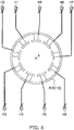
- FIG. 9 is a plan view showing the upper side of the stator 10 according to the present invention.
- three crossover wires (travelling lines) Lt1 to Lt3 extending between different teeth are formed in the stator 10.
- the first crossover wire Lt1 extends from the tooth T1 to the tooth T4.
- the second crossover wire Lt2 extends from the tooth T2 to the tooth T5.
- the third crossover wire Lt3 extends from the tooth T3 to the tooth T6.
- This stator 10, too, is manufactured using the winding device 100 described above.
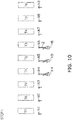
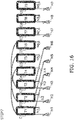
- FIGS. 10 to 17 respectively show first to eighth steps concerning the manufacture of the stator 10 according to the present invention.
- a layered product composed of the teeth T1 to T9 and the teeth covers 33 are illustrated as a simple rectangle.
- the plurality of nozzles N1 to N9 are located below the stator 10.
- the stator 10 and the winding device 100 are positioned in such a manner as to form a first relative angle that allows the tooth T1 to come close to the nozzle N4.
- Only the tips of the conductive wires Z ejected from the nozzles N4 to N6 are fixed to the fixing tools H4 to H6.
- the conductive wires Z thereof are not fixed.
- the stator 10 rotates relative to the winding device 100. Accordingly, the stator 10 and the winding device 100 are positioned in such a manner as to form a second relative angle that allows the tooth T1 to come close to the nozzle N1. This rotation causes a significant length of the conductive wires Z to be pulled from the nozzles N4 to N6.
- all of the nozzles N1 to N9 move to below the stator 10 along with the body 101 of the winding device 100.
- the conductive wires Z fixed to the fixing tools H4 to H6 are not extended in the vicinity of the teeth T1 to T3 but in the vicinity of the teeth T4 to T6.
- new conductive wires Z are fixed in the second relative angle using all of the fixing tools H1 to H9.
- the fixing tools H1 to H9 fix the conductive wires Z ejected from the nozzles N1 to N9, respectively.
- the nozzles N1 to N9 finish winding the conductive wires Z, forming the windings C1 to C9.
- the conductive wires Z fixed to the fixing tools H1 to H9 are released.
- the three crossover wires Lt1 to Lt3 described above are formed in the upper part of the stator 10.
- First lead wires La7 to La9 corresponding to the beginning of winding of the conductive wires Z and second lead wires Lb7 to Lb9 corresponding to the end of winding of the conductive wires Z extend from the teeth T7 to T9 respectively.
- Only second lead wires Lb4 to Lb6 extend from the teeth T4 to T6 respectively.
- Pairs of first lead wires La1 to La6 and each of second lead wires Lb1 to Lb3 extend from each of the teeth T1 to T3.
- the nine first lead wires La1 to La9 and the nine second lead wires Lb1 to Lb9 are connected in the connecting step to achieve the wiring shown in FIG 8 .
- the wiring is performed as described below.
- the first lead wires of the three windings belonging to the U phase which are namely the first lead wire La1 extending from a U1 winding C1, the first lead wire La4 extending from a U2 winding C4, and the first lead wire La7 extending from a U3 winding C7, are connected to the terminal PH-U, thereby configuring a U-phase power line PL.
- the first lead wires of the three windings belonging to the W phase which are namely the first lead wire La3 extending from a W1 winding C3, the first lead wire La6 extending from a W2 winding C6, and the first lead wire La9 extending from a W3 winding C9, are connected to the terminal PH-W, thereby configuring a W-phase power line PL.
- the crossover wires Lt1 to Lt3 extending between the teeth are formed in the manufacture of the stator 10. According to this manufacturing method, some of the first lead wires to be connected are arranged collectively due to the presence of the crossover wires Lt1 to Lt3. Therefore, not only is it possible to restrain connection of wrong lead wires, but also the efficiency of manufacturing the stator 10 can be improved.
- the stator core 20 and the nine nozzles N1 to N9 rotate relative to each other by the central angle corresponding to three teeth. This method improves the efficiency of manufacturing the stator 10 for the 3-phase motor 90. Even when the size of the central angle of the relative rotation is corresponding to an integral multiple of three teeth, such as six teeth or nine teeth, the same effects can be expected.
- crossover wires Lt1 to Lt3 extending between the teeth and the first lead wires La4 to La6 having these crossover wires Lt1 to Lt3 are extended at the stage of starting to wind the conductive wires Z, and held between the windings C1 to C9 to be formed subsequently and the stator core 20. This method can reduce the possibility that the crossover wires Lt1 to Lt3 and the first lead wires La4 to La6 are displaced.
- first lead wires belonging to the same phase are arranged collectively. Instead, all of the first lead wires belonging to the same phase may be arranged collectively.
- all of the first lead wires La1, La4, La7 that extend from the three windings C1, C4, C7 belonging to the U phase may be arranged in the vicinity of the same tooth T1.
- all of the three first lead wires belonging to the same phase are arranged collectively, further facilitating the connection of the lead wires.
- the motor 90 has the 3-phase 9-pole windings C1 to C9.
- the motor may have a different number of windings.
- the motor may have 3-phase 12-pole windings.
- the U1 winding C1, the U2 winding C4, the U3 winding C7, and a U4 winding C10 belong to the U phase.
- the V1 winding C2, the V2 winding C5, the V3 winding C8, and the V4 winding C11 belong to the V phase.
- the W1 winding C3, the W2 winding C6, the W3 winding C9, and the W4 winding C12 belong to the W phase.
- the first lead wires La1 to La12 may be arranged as follows.
- the two first lead wires La1, La4 of the U1 winding C1 and the U2 winding C4 extend from the same tooth T1.
- the two first lead wires La7, La10 of the U3 winding C7 and the U4 winding C4 extend from the same tooth T7.
- the two first lead wires La3, La6 of the W1 winding C3 and the W2 winding C6 extend from the same tooth T3.
- the two first lead wires La9, La12 of the W3 winding C9 and the W4 winding C12 extend from the same tooth T9.
- the first lead wires belonging to the same phase are arranged collectively in the motor having the twelve windings C1 to C12. This configuration can further facilitate connecting the lead wires.
- the first lead wires La1 to La9 that are wound first around the respective windings C1 to C9 constitute the power lines PL
- the second lead wires Lb1 to Lb9 that are wound around the windings C1 to C9 at the end constitute the neutral line NL
- the first lead wires La1 to La9 may be constitute the neutral line NL
- the second lead wires Lb1 to Lb9 may constitute the power lines PL.
- the present invention can be applied widely to various types of motors, including motors to be mounted on compressors of refrigerating apparatuses.
- Patent Literature 1 Japanese Patent Application Laid-open No. 2004-274878
Landscapes
- Engineering & Computer Science (AREA)
- Power Engineering (AREA)
- Manufacturing & Machinery (AREA)
- Manufacture Of Motors, Generators (AREA)
- Windings For Motors And Generators (AREA)
Claims (9)
- Stator (10) für einen Rotor mit gleichzeitiger konzentrierter Wicklung, umfassend:einen Kern (20) mit 3 × m Zähnen (T1 bis T9), die mindestens einen ersten Zahn (T1), einen zweiten Zahn (T2), einen dritten Zahn (T3), einen vierten Zahn (T4), einen fünften Zahn (T5) und einen sechsten Zahn (T6) enthalten, wobei m eine ganze Zahl, die größer als oder gleich 2 ist, repräsentiert, wobei der Kern eine zentrale Achse (A) aufweist;3 × m Wicklungen (C1 bis C9), die durch Wickeln von 3 × m Leitungsdrähten hergestellt sind, wobei jeder einer U-Phase, einer V-Phase oder einer W-Phase entspricht,wobei die Wicklungen auf den jeweiligen Zähnen angeordnet sind,wobei die 3 × m Wicklungen mindesten enthalten:eine U1-Wicklung (C1) und eine U2-Wicklung (C4), die zur U-Phase gehören;einen V1-Wicklung (C2) und eine V2-Wicklung (C5), die zur V-Phase gehören; undeine W1-Wicklung (C3) und eine W2-Wicklung (C6), die zur W-Phase gehören, und eine Vielzahl von ersten Leitungsdrähten (La1 bis La6) und eine Vielzahl von zweiten Leitungsdrähten (Lb1 bis Lb6), die sich von den jeweiligen Wicklungen erstrecken,dadurch gekennzeichnet, dass sich die ersten Leitungsdrähte der Ui-Wicklung, der V1-Wicklung und der W1-Wicklung vom ersten Zahn (T1), zweiten Zahn (T2) bzw. dritten Zahn (T3), auf denen die U1-Wicklung, die V1-Wicklung und die W1-Wicklung angeordnet sind, in einer Richtung erstrecken, in der sich eine zentrale Achse A erstreckt,wobei sich die ersten Leitungsdrähte der U2-Wicklung, der V2-Wicklung und der W2-Wicklung vom ersten Zahn (T1), zweiten Zahn (T2) bzw. dritten Zahn (T3), auf der U1-Wicklung, die V1-Wicklung und die W1-Wicklung angeordnet sind, in einer Richtung erstrecken, in der sich die zentrale Achse A erstreckt, undein erster Überkreuzungsdraht (Lt1), ein zweiter Überkreuzungsdraht (Lt2) und ein dritter Überkreuzungsdraht (Lt3), die sich zwischen verschiedenen Zähnen erstrecken, in dem Stator ausgebildet sind, wobei sich der erste Überkreuzungsdraht (Lt1) von dem ersten Zahn (T1) zu dem vierten Zahn (T4) erstreckt, sich der zweite Überkreuzungsdraht (Lt2) von dem zweiten Zahn (T2) zu dem fünften Zahn (T5) erstreckt und sich der dritte Überkreuzungsdraht (Lt3) von dem dritten Zahn (T3) zu dem sechsten Zahn (T6) erstreckt.
- Stator nach Anspruch 1, wobei die 3 × m Zähne (T1 bis T9) ferner einen siebten Zahn (T7), einen achten Zahn (T8) und einen neunten Zahn (T9) enthalten,
die 3 × m Wicklungen ferner enthalten:eine U3-Wicklung (C7), die zur U-Phase gehört;eine V3-Wicklung (C8), die zur V-Phase gehört; undeine W3-Wicklung (C9), die zur W-Phase gehört, undsich die ersten Leitungsdrähte der U3-Wicklung, der V3-Wicklung und der W3-Wicklung vom siebten Zahn (T7) bzw. achten Zahn (T8) bzw. neunten Zahn (T9), auf denen die U3-Wicklung, die V3-Wicklung und die W3-Wicklung angeordnet sind, in einer Richtung erstrecken, in der sich die zentrale Achse (A) erstreckt. - Stator nach Anspruch 1, wobei die 3 × m Zähne (T1 bis T9) ferner einen siebten Zahn (T7), einen achten Zahn (T8) und einen neunten Zahn (T9) enthalten, die 3 × m Wicklungen ferner enthalten:eine U3-Wicklung (C7), die zur U-Phase gehört;eine V3-Wicklung (C8), die zur V-Phase gehört; undeine W3-Wicklung (C9), die zur W-Phase gehört, undsich die ersten Leitungsdrähte der U3-Wicklung, der V3-Wicklung und der W3-Wicklung von dem ersten Zahn (T1), dem zweiten Zahn (T2) bzw. dem dritten Zahn (T3), auf dem die U1-Wicklung, die V1-Wicklung und die W1-Wicklung angeordnet sind, in einer Richtung erstrecken, in der sich die zentrale Achse (A) erstreckt.
- Stator nach Anspruch 1, wobei die 3 × m Zähne (T1 bis T9) ferner einen siebten Zahn (T7), einen achten Zahn (T8) und einen neunten Zahn (T9), einen zehnten Zahn (T10), einen elften Zahn (T11) und einen zwölften Zahn (T12) enthalten, wobei die 3 × m Wicklungen ferner enthalten:eine U3-Wicklung (C7) und eine U4-Wicklung (C10), die z der U-Phase gehören;eine V3-Wicklung (C8) und eine V4-Wicklung (C11), die zu der V-Phase gehören, undeine W3-Wicklung (C9) und eine W4-Wicklung (C12), die zur W-Phase gehören,wobei sich die ersten Leitungsdrähte der U3-Wicklung, der V3-Wicklung und der W3-Wicklung von den Zähnen T7, T8, T9, auf denen die U3-Wicklung, die V3-Wicklung und die W3-Wicklung angeordnet sind, erstrecken undsich die ersten Leitungsdrähte der U4-Wicklung, der V4-Wicklung und der W4-Wicklung von dem siebten Zahn (T7), dem achten Zahn (T8) bzw. dem neunten Zahn (T9), auf denen die U3-Wicklung, die V3-Wickung und die W3-Wicklung angeordnet sind, in einer Richtung erstrecken, in der sich die zentrale Achse (A) erstreckt.
- Stator nach einem der Ansprüche 1 bis 4, wobei alle der zweiten Leitungsdrähte (Lb) der 3 × m Wicklungen sich jeweils von den Zähnen, auf denen diese Wicklungen angeordnet sind, erstrecken.
- Motor, umfassend:den Stator nach einem der Ansprüche 1 bis 5; undeinen Rotor, der einen Dauermagneten aufweist, der mit dem Stator magnetisch wechselwirkt.
- Verfahren zur Herstellung eines Stators (10) durch Wickeln von 3 × m Leitungsdrähten um 3 × m Zähne (T1 bis T9), die mindestens einen ersten Zahn (T1), einen zweiten Zahn (T2), einen dritten Zahn (T3), einen vierten Zahn (T4), einen fünften Zahn (T5) und einen sechsten Zahn (T6) enthalten, eines Kerns (20) mit einer zentralen Achse (A), dadurch 3 × m Wicklungen (C1 bis C9), die die Zähne umgeben, und 6 × m Leitungsdrähte (La1 bis La6, Lb1 bis Lb6) bildend, die sich von beiden Enden von jeder der Wicklungen in einer Richtung erstrecken, in der sich eine zentrale Achse A erstreckt, wobei m eine ganze Zahl ist, die größer als oder gleich 2 ist, wobei das Verfahren die Schritte umfasst:Vorbereiten einer Wickeleinrichtung mit 3 × m Düsen (N1 bis N9), die sich um die Zähne bewegen können, während sie die 3 × m Leitungsdrähte in einer radialen Richtung ejizieren;Ausbilden eines ersten relativen Winkels zwischen der Wickeleinrichtung und dem Kern;Fixieren eines Teils der 3 × m Leitungsdrähten mittels eines Fixierwerkzeugs (H4 bis H6) und Unfixiertlassen der restlichen Leitungsdrähte;Bewegen von jeder der 3 × m Düsen um einen der 3 × m Zähne;Ausbilden eines zweiten relativen Winkels zwischen der Wickeleinrichtung und dem Kern, indem die Wickeleinrichtung relativ um eine zentrale Achse (A) des Kerns drehen gelassen wird;Fixieren aller der 3 × m Leitungsdrähte mittels eines Fixierwerkzeugs (H1 bis H9);Bewegen von jeder der 3 × m Düsen um einen der 3 × m Zähne; undAusbilden eines ersten Überkreuzungsdrahts (Lt1), eines zweiten Überkreuzungsdrahts (Lt2) und eines dritten Überkreuzungsdrahts (Lt3), die sich zwischen verschiedenen Zähnen erstrecken, die in dem Stator ausgebildet sind, wobei sich der erste Überkreuzungsdraht (Lt1) von dem ersten Zahn (T1) zum vierten Zahn (T4) erstreckt, sich der zweite Überkreuzungsdraht (Lt2) von dem zweiten Zahn (T2) zu dem fünften Zahn (T5) erstreckt und sich der dritte Überkreuzungsdraht (Lt3) von dem dritten Zahn (T3) zu dem sechsten Zahn (T6) erstreckt.
- Verfahren nach Anspruch 7, wobei sich der Kern und die Wickeleinrichtung relativ zueinander um einen zentralen Winkel, der einem ganzen Vielfachen der drei Zähne entspricht, drehen.
- Verfahren nach Anspruch 7 oder 8, wobei 3 × m Wicklungen in einen Zustand ausgebildet werden, in dem die Wickeleinrichtung und der Kern den zweiten relativen Winkel bilden.
Applications Claiming Priority (2)
| Application Number | Priority Date | Filing Date | Title |
|---|---|---|---|
| JP2015192936A JP6079847B1 (ja) | 2015-09-30 | 2015-09-30 | 固定子、固定子を用いたモータ、および固定子の製造方法 |
| PCT/JP2016/078319 WO2017057297A1 (ja) | 2015-09-30 | 2016-09-26 | 固定子、固定子を用いたモータ、および固定子の製造方法 |
Publications (3)
| Publication Number | Publication Date |
|---|---|
| EP3358718A1 EP3358718A1 (de) | 2018-08-08 |
| EP3358718A4 EP3358718A4 (de) | 2018-09-05 |
| EP3358718B1 true EP3358718B1 (de) | 2020-07-29 |
Family
ID=58043236
Family Applications (1)
| Application Number | Title | Priority Date | Filing Date |
|---|---|---|---|
| EP16851468.5A Active EP3358718B1 (de) | 2015-09-30 | 2016-09-26 | Stator, motor mit dem stator und verfahren zur herstellung des stators |
Country Status (9)
| Country | Link |
|---|---|
| US (1) | US10637306B2 (de) |
| EP (1) | EP3358718B1 (de) |
| JP (1) | JP6079847B1 (de) |
| KR (1) | KR101867262B1 (de) |
| CN (1) | CN108141086B (de) |
| AU (1) | AU2016331554B2 (de) |
| BR (1) | BR112018003295B1 (de) |
| ES (1) | ES2818274T3 (de) |
| WO (1) | WO2017057297A1 (de) |
Families Citing this family (1)
| Publication number | Priority date | Publication date | Assignee | Title |
|---|---|---|---|---|
| JP7371714B2 (ja) * | 2022-03-08 | 2023-10-31 | 株式会社富士通ゼネラル | 3相モータの製造方法及び3相モータ |
Family Cites Families (15)
| Publication number | Priority date | Publication date | Assignee | Title |
|---|---|---|---|---|
| JPS61173650A (ja) * | 1985-01-25 | 1986-08-05 | Toshiba Corp | 回転電機の自動巻装装置 |
| JPH06245442A (ja) * | 1993-02-12 | 1994-09-02 | Shibaura Eng Works Co Ltd | 回転電機の製造方法 |
| JP3559172B2 (ja) * | 1998-08-10 | 2004-08-25 | 三菱電機株式会社 | 回転電機のアマチュア及びその製造方法 |
| JP3576106B2 (ja) * | 2000-02-04 | 2004-10-13 | 松下エコシステムズ株式会社 | コンデンサ電動機固定子およびその製造方法 |
| US6727625B2 (en) * | 2000-09-25 | 2004-04-27 | Denso Corporation | Rotary electric machine and method for manufacturing the same |
| JP2003189525A (ja) * | 2001-12-20 | 2003-07-04 | Hitachi Ltd | 回転電機 |
| JP3753699B2 (ja) | 2003-03-07 | 2006-03-08 | 三工機器株式会社 | ステータコアへの巻線方法及び同方法によって巻線されたコイル付きステータコア |
| US7701102B2 (en) * | 2004-02-06 | 2010-04-20 | Daikin Industries, Ltd. | Electric motor stator |
| EP2104206B1 (de) * | 2006-12-27 | 2018-03-21 | Toshiba Carrier Corporation | Wickelverfahren für einen stator und permanentmagnet-elektromotor |
| US8653711B2 (en) | 2010-04-01 | 2014-02-18 | Globe Motors, Inc. | Parallel wound stator |
| DE112012004866B4 (de) * | 2011-11-22 | 2024-03-14 | Honda Motor Co., Ltd. | Elektrische Umlaufmaschine |
| US20130200742A1 (en) | 2012-02-08 | 2013-08-08 | Asmo Co., Ltd. | Stator, brushless motor, stator manufacturing method |
| JP2014011937A (ja) * | 2012-07-03 | 2014-01-20 | Aisin Aw Co Ltd | ステータ |
| JP6098920B2 (ja) * | 2012-10-19 | 2017-03-22 | 日本電産株式会社 | ステータユニットおよびモータ |
| JP6107386B2 (ja) | 2013-04-26 | 2017-04-05 | ダイキン工業株式会社 | モータ及び圧縮機 |
-
2015
- 2015-09-30 JP JP2015192936A patent/JP6079847B1/ja active Active
-
2016
- 2016-09-26 EP EP16851468.5A patent/EP3358718B1/de active Active
- 2016-09-26 CN CN201680056412.4A patent/CN108141086B/zh active Active
- 2016-09-26 US US15/762,514 patent/US10637306B2/en active Active
- 2016-09-26 ES ES16851468T patent/ES2818274T3/es active Active
- 2016-09-26 KR KR1020187011816A patent/KR101867262B1/ko not_active Expired - Fee Related
- 2016-09-26 WO PCT/JP2016/078319 patent/WO2017057297A1/ja not_active Ceased
- 2016-09-26 BR BR112018003295-6A patent/BR112018003295B1/pt not_active IP Right Cessation
- 2016-09-26 AU AU2016331554A patent/AU2016331554B2/en not_active Ceased
Non-Patent Citations (1)
| Title |
|---|
| None * |
Also Published As
| Publication number | Publication date |
|---|---|
| AU2016331554A1 (en) | 2018-05-10 |
| BR112018003295A2 (pt) | 2018-09-25 |
| BR112018003295B1 (pt) | 2022-08-09 |
| WO2017057297A1 (ja) | 2017-04-06 |
| US10637306B2 (en) | 2020-04-28 |
| KR20180050419A (ko) | 2018-05-14 |
| US20180278101A1 (en) | 2018-09-27 |
| EP3358718A4 (de) | 2018-09-05 |
| JP6079847B1 (ja) | 2017-02-15 |
| KR101867262B1 (ko) | 2018-06-12 |
| AU2016331554B2 (en) | 2018-05-10 |
| JP2017070091A (ja) | 2017-04-06 |
| ES2818274T3 (es) | 2021-04-09 |
| CN108141086A (zh) | 2018-06-08 |
| CN108141086B (zh) | 2019-07-30 |
| EP3358718A1 (de) | 2018-08-08 |
Similar Documents
| Publication | Publication Date | Title |
|---|---|---|
| JP5741747B1 (ja) | インシュレータおよびそれを用いたブラシレスdcモータ | |
| JP6068953B2 (ja) | 電動モータ | |
| JP2009106003A (ja) | 回転電機 | |
| JP6626514B2 (ja) | 回転電機 | |
| CN106469949A (zh) | 马达以及马达的制造方法 | |
| EP3358718B1 (de) | Stator, motor mit dem stator und verfahren zur herstellung des stators | |
| CN112821598A (zh) | 一种电机定子及电机 | |
| WO2016051978A1 (ja) | 回転電機の固定子、及びこれを備えた回転電機 | |
| JP2016101031A (ja) | 三相モータのステータ | |
| JP7176394B2 (ja) | 回転電機 | |
| JP2010183662A (ja) | 固定子及びモータ | |
| JP5334167B2 (ja) | 磁石式発電機 | |
| JP2019037103A (ja) | ステータ及びモータ | |
| CN213367495U (zh) | 三相外转子电机的定子结构 | |
| CN111478484A (zh) | 一种电机定子及电机 | |
| TWI900182B (zh) | 馬達定子結構 | |
| CN218243125U (zh) | 一种定子及电机 | |
| CN214626538U (zh) | 一种电机定子及电机 | |
| JP2014192997A (ja) | 電動モータ | |
| JP2019037132A (ja) | ステータの製造方法およびブラシレスモータの製造方法 | |
| US20220209605A1 (en) | Stator design for electrical machine | |
| KR20250126228A (ko) | 축방향 자속 모터의 코일 권선방법 | |
| JP5958766B2 (ja) | 回転電機の固定子の巻線方法、巻線装置、及び回転電機の固定子 | |
| CN112436620A (zh) | 一种电机定子及电机 | |
| CN112271835A (zh) | 三相外转子电机的定子结构 |
Legal Events
| Date | Code | Title | Description |
|---|---|---|---|
| STAA | Information on the status of an ep patent application or granted ep patent |
Free format text: STATUS: THE INTERNATIONAL PUBLICATION HAS BEEN MADE |
|
| PUAI | Public reference made under article 153(3) epc to a published international application that has entered the european phase |
Free format text: ORIGINAL CODE: 0009012 |
|
| STAA | Information on the status of an ep patent application or granted ep patent |
Free format text: STATUS: REQUEST FOR EXAMINATION WAS MADE |
|
| 17P | Request for examination filed |
Effective date: 20180406 |
|
| AK | Designated contracting states |
Kind code of ref document: A1 Designated state(s): AL AT BE BG CH CY CZ DE DK EE ES FI FR GB GR HR HU IE IS IT LI LT LU LV MC MK MT NL NO PL PT RO RS SE SI SK SM TR |
|
| AX | Request for extension of the european patent |
Extension state: BA ME |
|
| RIC1 | Information provided on ipc code assigned before grant |
Ipc: H02K 3/18 20060101AFI20180726BHEP Ipc: H02K 15/095 20060101ALI20180726BHEP |
|
| A4 | Supplementary search report drawn up and despatched |
Effective date: 20180803 |
|
| DAV | Request for validation of the european patent (deleted) | ||
| DAX | Request for extension of the european patent (deleted) | ||
| STAA | Information on the status of an ep patent application or granted ep patent |
Free format text: STATUS: EXAMINATION IS IN PROGRESS |
|
| 17Q | First examination report despatched |
Effective date: 20190716 |
|
| GRAP | Despatch of communication of intention to grant a patent |
Free format text: ORIGINAL CODE: EPIDOSNIGR1 |
|
| STAA | Information on the status of an ep patent application or granted ep patent |
Free format text: STATUS: GRANT OF PATENT IS INTENDED |
|
| INTG | Intention to grant announced |
Effective date: 20200317 |
|
| GRAS | Grant fee paid |
Free format text: ORIGINAL CODE: EPIDOSNIGR3 |
|
| GRAA | (expected) grant |
Free format text: ORIGINAL CODE: 0009210 |
|
| STAA | Information on the status of an ep patent application or granted ep patent |
Free format text: STATUS: THE PATENT HAS BEEN GRANTED |
|
| AK | Designated contracting states |
Kind code of ref document: B1 Designated state(s): AL AT BE BG CH CY CZ DE DK EE ES FI FR GB GR HR HU IE IS IT LI LT LU LV MC MK MT NL NO PL PT RO RS SE SI SK SM TR |
|
| REG | Reference to a national code |
Ref country code: CH Ref legal event code: EP |
|
| REG | Reference to a national code |
Ref country code: DE Ref legal event code: R096 Ref document number: 602016041038 Country of ref document: DE |
|
| REG | Reference to a national code |
Ref country code: AT Ref legal event code: REF Ref document number: 1296936 Country of ref document: AT Kind code of ref document: T Effective date: 20200815 |
|
| REG | Reference to a national code |
Ref country code: IE Ref legal event code: FG4D |
|
| REG | Reference to a national code |
Ref country code: LT Ref legal event code: MG4D |
|
| REG | Reference to a national code |
Ref country code: NL Ref legal event code: MP Effective date: 20200729 |
|
| REG | Reference to a national code |
Ref country code: AT Ref legal event code: MK05 Ref document number: 1296936 Country of ref document: AT Kind code of ref document: T Effective date: 20200729 |
|
| PG25 | Lapsed in a contracting state [announced via postgrant information from national office to epo] |
Ref country code: LT Free format text: LAPSE BECAUSE OF FAILURE TO SUBMIT A TRANSLATION OF THE DESCRIPTION OR TO PAY THE FEE WITHIN THE PRESCRIBED TIME-LIMIT Effective date: 20200729 Ref country code: HR Free format text: LAPSE BECAUSE OF FAILURE TO SUBMIT A TRANSLATION OF THE DESCRIPTION OR TO PAY THE FEE WITHIN THE PRESCRIBED TIME-LIMIT Effective date: 20200729 Ref country code: GR Free format text: LAPSE BECAUSE OF FAILURE TO SUBMIT A TRANSLATION OF THE DESCRIPTION OR TO PAY THE FEE WITHIN THE PRESCRIBED TIME-LIMIT Effective date: 20201030 Ref country code: NO Free format text: LAPSE BECAUSE OF FAILURE TO SUBMIT A TRANSLATION OF THE DESCRIPTION OR TO PAY THE FEE WITHIN THE PRESCRIBED TIME-LIMIT Effective date: 20201029 Ref country code: BG Free format text: LAPSE BECAUSE OF FAILURE TO SUBMIT A TRANSLATION OF THE DESCRIPTION OR TO PAY THE FEE WITHIN THE PRESCRIBED TIME-LIMIT Effective date: 20201029 Ref country code: AT Free format text: LAPSE BECAUSE OF FAILURE TO SUBMIT A TRANSLATION OF THE DESCRIPTION OR TO PAY THE FEE WITHIN THE PRESCRIBED TIME-LIMIT Effective date: 20200729 Ref country code: FI Free format text: LAPSE BECAUSE OF FAILURE TO SUBMIT A TRANSLATION OF THE DESCRIPTION OR TO PAY THE FEE WITHIN THE PRESCRIBED TIME-LIMIT Effective date: 20200729 Ref country code: PT Free format text: LAPSE BECAUSE OF FAILURE TO SUBMIT A TRANSLATION OF THE DESCRIPTION OR TO PAY THE FEE WITHIN THE PRESCRIBED TIME-LIMIT Effective date: 20201130 Ref country code: SE Free format text: LAPSE BECAUSE OF FAILURE TO SUBMIT A TRANSLATION OF THE DESCRIPTION OR TO PAY THE FEE WITHIN THE PRESCRIBED TIME-LIMIT Effective date: 20200729 |
|
| PG25 | Lapsed in a contracting state [announced via postgrant information from national office to epo] |
Ref country code: RS Free format text: LAPSE BECAUSE OF FAILURE TO SUBMIT A TRANSLATION OF THE DESCRIPTION OR TO PAY THE FEE WITHIN THE PRESCRIBED TIME-LIMIT Effective date: 20200729 Ref country code: PL Free format text: LAPSE BECAUSE OF FAILURE TO SUBMIT A TRANSLATION OF THE DESCRIPTION OR TO PAY THE FEE WITHIN THE PRESCRIBED TIME-LIMIT Effective date: 20200729 Ref country code: LV Free format text: LAPSE BECAUSE OF FAILURE TO SUBMIT A TRANSLATION OF THE DESCRIPTION OR TO PAY THE FEE WITHIN THE PRESCRIBED TIME-LIMIT Effective date: 20200729 Ref country code: IS Free format text: LAPSE BECAUSE OF FAILURE TO SUBMIT A TRANSLATION OF THE DESCRIPTION OR TO PAY THE FEE WITHIN THE PRESCRIBED TIME-LIMIT Effective date: 20201129 |
|
| PG25 | Lapsed in a contracting state [announced via postgrant information from national office to epo] |
Ref country code: NL Free format text: LAPSE BECAUSE OF FAILURE TO SUBMIT A TRANSLATION OF THE DESCRIPTION OR TO PAY THE FEE WITHIN THE PRESCRIBED TIME-LIMIT Effective date: 20200729 |
|
| REG | Reference to a national code |
Ref country code: ES Ref legal event code: FG2A Ref document number: 2818274 Country of ref document: ES Kind code of ref document: T3 Effective date: 20210409 |
|
| PG25 | Lapsed in a contracting state [announced via postgrant information from national office to epo] |
Ref country code: EE Free format text: LAPSE BECAUSE OF FAILURE TO SUBMIT A TRANSLATION OF THE DESCRIPTION OR TO PAY THE FEE WITHIN THE PRESCRIBED TIME-LIMIT Effective date: 20200729 Ref country code: SM Free format text: LAPSE BECAUSE OF FAILURE TO SUBMIT A TRANSLATION OF THE DESCRIPTION OR TO PAY THE FEE WITHIN THE PRESCRIBED TIME-LIMIT Effective date: 20200729 Ref country code: RO Free format text: LAPSE BECAUSE OF FAILURE TO SUBMIT A TRANSLATION OF THE DESCRIPTION OR TO PAY THE FEE WITHIN THE PRESCRIBED TIME-LIMIT Effective date: 20200729 Ref country code: DK Free format text: LAPSE BECAUSE OF FAILURE TO SUBMIT A TRANSLATION OF THE DESCRIPTION OR TO PAY THE FEE WITHIN THE PRESCRIBED TIME-LIMIT Effective date: 20200729 Ref country code: CZ Free format text: LAPSE BECAUSE OF FAILURE TO SUBMIT A TRANSLATION OF THE DESCRIPTION OR TO PAY THE FEE WITHIN THE PRESCRIBED TIME-LIMIT Effective date: 20200729 |
|
| REG | Reference to a national code |
Ref country code: CH Ref legal event code: PL Ref country code: DE Ref legal event code: R097 Ref document number: 602016041038 Country of ref document: DE |
|
| PG25 | Lapsed in a contracting state [announced via postgrant information from national office to epo] |
Ref country code: AL Free format text: LAPSE BECAUSE OF FAILURE TO SUBMIT A TRANSLATION OF THE DESCRIPTION OR TO PAY THE FEE WITHIN THE PRESCRIBED TIME-LIMIT Effective date: 20200729 |
|
| PLBE | No opposition filed within time limit |
Free format text: ORIGINAL CODE: 0009261 |
|
| STAA | Information on the status of an ep patent application or granted ep patent |
Free format text: STATUS: NO OPPOSITION FILED WITHIN TIME LIMIT |
|
| REG | Reference to a national code |
Ref country code: BE Ref legal event code: MM Effective date: 20200930 |
|
| GBPC | Gb: european patent ceased through non-payment of renewal fee |
Effective date: 20201029 |
|
| PG25 | Lapsed in a contracting state [announced via postgrant information from national office to epo] |
Ref country code: LU Free format text: LAPSE BECAUSE OF NON-PAYMENT OF DUE FEES Effective date: 20200926 Ref country code: SK Free format text: LAPSE BECAUSE OF FAILURE TO SUBMIT A TRANSLATION OF THE DESCRIPTION OR TO PAY THE FEE WITHIN THE PRESCRIBED TIME-LIMIT Effective date: 20200729 |
|
| 26N | No opposition filed |
Effective date: 20210430 |
|
| PG25 | Lapsed in a contracting state [announced via postgrant information from national office to epo] |
Ref country code: CH Free format text: LAPSE BECAUSE OF NON-PAYMENT OF DUE FEES Effective date: 20200930 Ref country code: BE Free format text: LAPSE BECAUSE OF NON-PAYMENT OF DUE FEES Effective date: 20200930 Ref country code: LI Free format text: LAPSE BECAUSE OF NON-PAYMENT OF DUE FEES Effective date: 20200930 Ref country code: IE Free format text: LAPSE BECAUSE OF NON-PAYMENT OF DUE FEES Effective date: 20200926 Ref country code: GB Free format text: LAPSE BECAUSE OF NON-PAYMENT OF DUE FEES Effective date: 20201029 Ref country code: SI Free format text: LAPSE BECAUSE OF FAILURE TO SUBMIT A TRANSLATION OF THE DESCRIPTION OR TO PAY THE FEE WITHIN THE PRESCRIBED TIME-LIMIT Effective date: 20200729 |
|
| PG25 | Lapsed in a contracting state [announced via postgrant information from national office to epo] |
Ref country code: MT Free format text: LAPSE BECAUSE OF FAILURE TO SUBMIT A TRANSLATION OF THE DESCRIPTION OR TO PAY THE FEE WITHIN THE PRESCRIBED TIME-LIMIT Effective date: 20200729 Ref country code: CY Free format text: LAPSE BECAUSE OF FAILURE TO SUBMIT A TRANSLATION OF THE DESCRIPTION OR TO PAY THE FEE WITHIN THE PRESCRIBED TIME-LIMIT Effective date: 20200729 |
|
| PG25 | Lapsed in a contracting state [announced via postgrant information from national office to epo] |
Ref country code: MK Free format text: LAPSE BECAUSE OF FAILURE TO SUBMIT A TRANSLATION OF THE DESCRIPTION OR TO PAY THE FEE WITHIN THE PRESCRIBED TIME-LIMIT Effective date: 20200729 Ref country code: MC Free format text: LAPSE BECAUSE OF FAILURE TO SUBMIT A TRANSLATION OF THE DESCRIPTION OR TO PAY THE FEE WITHIN THE PRESCRIBED TIME-LIMIT Effective date: 20200729 |
|
| P01 | Opt-out of the competence of the unified patent court (upc) registered |
Effective date: 20230525 |
|
| PGFP | Annual fee paid to national office [announced via postgrant information from national office to epo] |
Ref country code: DE Payment date: 20250730 Year of fee payment: 10 |
|
| PGFP | Annual fee paid to national office [announced via postgrant information from national office to epo] |
Ref country code: TR Payment date: 20250919 Year of fee payment: 10 Ref country code: IT Payment date: 20250825 Year of fee payment: 10 |
|
| PGFP | Annual fee paid to national office [announced via postgrant information from national office to epo] |
Ref country code: FR Payment date: 20250808 Year of fee payment: 10 |
|
| PGFP | Annual fee paid to national office [announced via postgrant information from national office to epo] |
Ref country code: ES Payment date: 20251013 Year of fee payment: 10 |