EP3357848B1 - Bobbin for thermal transfer sheet or image receiving sheet, combined body of bobbin and sheet, and thermal transfer printer - Google Patents
Bobbin for thermal transfer sheet or image receiving sheet, combined body of bobbin and sheet, and thermal transfer printer Download PDFInfo
- Publication number
- EP3357848B1 EP3357848B1 EP16870672.9A EP16870672A EP3357848B1 EP 3357848 B1 EP3357848 B1 EP 3357848B1 EP 16870672 A EP16870672 A EP 16870672A EP 3357848 B1 EP3357848 B1 EP 3357848B1
- Authority
- EP
- European Patent Office
- Prior art keywords
- bobbin
- thermal transfer
- sheet
- gear
- image
- Prior art date
- Legal status (The legal status is an assumption and is not a legal conclusion. Google has not performed a legal analysis and makes no representation as to the accuracy of the status listed.)
- Active
Links
- 239000000470 constituent Substances 0.000 description 5
- 230000004048 modification Effects 0.000 description 4
- 238000012986 modification Methods 0.000 description 4
- 230000015572 biosynthetic process Effects 0.000 description 2
- 238000006748 scratching Methods 0.000 description 2
- 230000002393 scratching effect Effects 0.000 description 2
- 230000000694 effects Effects 0.000 description 1
- 238000004519 manufacturing process Methods 0.000 description 1
- 238000004804 winding Methods 0.000 description 1
Images


Classifications
-
- B—PERFORMING OPERATIONS; TRANSPORTING
- B65—CONVEYING; PACKING; STORING; HANDLING THIN OR FILAMENTARY MATERIAL
- B65H—HANDLING THIN OR FILAMENTARY MATERIAL, e.g. SHEETS, WEBS, CABLES
- B65H75/00—Storing webs, tapes, or filamentary material, e.g. on reels
- B65H75/02—Cores, formers, supports, or holders for coiled, wound, or folded material, e.g. reels, spindles, bobbins, cop tubes, cans, mandrels or chucks
- B65H75/18—Constructional details
- B65H75/30—Arrangements to facilitate driving or braking
-
- B—PERFORMING OPERATIONS; TRANSPORTING
- B41—PRINTING; LINING MACHINES; TYPEWRITERS; STAMPS
- B41J—TYPEWRITERS; SELECTIVE PRINTING MECHANISMS, i.e. MECHANISMS PRINTING OTHERWISE THAN FROM A FORME; CORRECTION OF TYPOGRAPHICAL ERRORS
- B41J2/00—Typewriters or selective printing mechanisms characterised by the printing or marking process for which they are designed
- B41J2/315—Typewriters or selective printing mechanisms characterised by the printing or marking process for which they are designed characterised by selective application of heat to a heat sensitive printing or impression-transfer material
- B41J2/32—Typewriters or selective printing mechanisms characterised by the printing or marking process for which they are designed characterised by selective application of heat to a heat sensitive printing or impression-transfer material using thermal heads
- B41J2/325—Typewriters or selective printing mechanisms characterised by the printing or marking process for which they are designed characterised by selective application of heat to a heat sensitive printing or impression-transfer material using thermal heads by selective transfer of ink from ink carrier, e.g. from ink ribbon or sheet
-
- B—PERFORMING OPERATIONS; TRANSPORTING
- B41—PRINTING; LINING MACHINES; TYPEWRITERS; STAMPS
- B41J—TYPEWRITERS; SELECTIVE PRINTING MECHANISMS, i.e. MECHANISMS PRINTING OTHERWISE THAN FROM A FORME; CORRECTION OF TYPOGRAPHICAL ERRORS
- B41J17/00—Mechanisms for manipulating page-width impression-transfer material, e.g. carbon paper
- B41J17/22—Supply arrangements for webs of impression-transfer material
- B41J17/24—Webs supplied from reels or spools attached to the machine
-
- B—PERFORMING OPERATIONS; TRANSPORTING
- B41—PRINTING; LINING MACHINES; TYPEWRITERS; STAMPS
- B41J—TYPEWRITERS; SELECTIVE PRINTING MECHANISMS, i.e. MECHANISMS PRINTING OTHERWISE THAN FROM A FORME; CORRECTION OF TYPOGRAPHICAL ERRORS
- B41J17/00—Mechanisms for manipulating page-width impression-transfer material, e.g. carbon paper
- B41J17/32—Detachable carriers or holders for impression-transfer material mechanism
-
- B—PERFORMING OPERATIONS; TRANSPORTING
- B41—PRINTING; LINING MACHINES; TYPEWRITERS; STAMPS
- B41J—TYPEWRITERS; SELECTIVE PRINTING MECHANISMS, i.e. MECHANISMS PRINTING OTHERWISE THAN FROM A FORME; CORRECTION OF TYPOGRAPHICAL ERRORS
- B41J32/00—Ink-ribbon cartridges
-
- B—PERFORMING OPERATIONS; TRANSPORTING
- B41—PRINTING; LINING MACHINES; TYPEWRITERS; STAMPS
- B41J—TYPEWRITERS; SELECTIVE PRINTING MECHANISMS, i.e. MECHANISMS PRINTING OTHERWISE THAN FROM A FORME; CORRECTION OF TYPOGRAPHICAL ERRORS
- B41J33/00—Apparatus or arrangements for feeding ink ribbons or like character-size impression-transfer material
- B41J33/14—Ribbon-feed devices or mechanisms
- B41J33/16—Ribbon-feed devices or mechanisms with drive applied to spool or spool spindle
- B41J33/22—Ribbon-feed devices or mechanisms with drive applied to spool or spool spindle by gears or pulleys
-
- B—PERFORMING OPERATIONS; TRANSPORTING
- B65—CONVEYING; PACKING; STORING; HANDLING THIN OR FILAMENTARY MATERIAL
- B65H—HANDLING THIN OR FILAMENTARY MATERIAL, e.g. SHEETS, WEBS, CABLES
- B65H75/00—Storing webs, tapes, or filamentary material, e.g. on reels
- B65H75/02—Cores, formers, supports, or holders for coiled, wound, or folded material, e.g. reels, spindles, bobbins, cop tubes, cans, mandrels or chucks
- B65H75/04—Kinds or types
- B65H75/08—Kinds or types of circular or polygonal cross-section
- B65H75/10—Kinds or types of circular or polygonal cross-section without flanges, e.g. cop tubes
-
- B—PERFORMING OPERATIONS; TRANSPORTING
- B65—CONVEYING; PACKING; STORING; HANDLING THIN OR FILAMENTARY MATERIAL
- B65H—HANDLING THIN OR FILAMENTARY MATERIAL, e.g. SHEETS, WEBS, CABLES
- B65H75/00—Storing webs, tapes, or filamentary material, e.g. on reels
- B65H75/02—Cores, formers, supports, or holders for coiled, wound, or folded material, e.g. reels, spindles, bobbins, cop tubes, cans, mandrels or chucks
- B65H75/18—Constructional details
-
- B—PERFORMING OPERATIONS; TRANSPORTING
- B41—PRINTING; LINING MACHINES; TYPEWRITERS; STAMPS
- B41J—TYPEWRITERS; SELECTIVE PRINTING MECHANISMS, i.e. MECHANISMS PRINTING OTHERWISE THAN FROM A FORME; CORRECTION OF TYPOGRAPHICAL ERRORS
- B41J2202/00—Embodiments of or processes related to ink-jet or thermal heads
- B41J2202/30—Embodiments of or processes related to thermal heads
-
- B—PERFORMING OPERATIONS; TRANSPORTING
- B65—CONVEYING; PACKING; STORING; HANDLING THIN OR FILAMENTARY MATERIAL
- B65H—HANDLING THIN OR FILAMENTARY MATERIAL, e.g. SHEETS, WEBS, CABLES
- B65H2701/00—Handled material; Storage means
- B65H2701/10—Handled articles or webs
- B65H2701/19—Specific article or web
- B65H2701/1928—Printing plate
-
- B—PERFORMING OPERATIONS; TRANSPORTING
- B65—CONVEYING; PACKING; STORING; HANDLING THIN OR FILAMENTARY MATERIAL
- B65H—HANDLING THIN OR FILAMENTARY MATERIAL, e.g. SHEETS, WEBS, CABLES
- B65H2801/00—Application field
- B65H2801/03—Image reproduction devices
Definitions
- the present invention relates to a bobbin for a thermal transfer sheet or an image-receiving sheet, a bobbin/sheet assembly, and a thermal transfer printer.
- Thermal transfer printers are widely prevalent which print characters or images on an object, such as an image-receiving sheet, by using an ink ribbon (thermal transfer sheet).
- the ink ribbon includes a ribbon (support layer) extending in a strip shape, and an ink layer containing a dye, etc. and formed on the ribbon.
- the ink ribbon is mounted and wound on a bobbin.
- the bobbin on which the ink ribbon is wound, generally includes a bobbin body and a driving flange mounted on the bobbin body as a separate member from the bobbin body.
- a driving flange mounted on the bobbin body as a separate member from the bobbin body.
- JP H10 129067 A describes an ink film cassette comprising a supply reel to which an ink film is wound around, a wind-up reel that winds up the ink film, a first torque limiter for applying a braking force to the supply reel in the cassette, a second torque limiter for restricting driving torque of the wind-up reel in the cassette, a bottom frame for holding both of the reels and an upper frame that holds both of the torque limiters and is detachably fixed to the bottom frame.
- the present invention has been made in view of the above situation. It is therefore an object of the present invention to provide a bobbin for a thermal transfer sheet or an image-receiving sheet, an assembly of a bobbin and a sheet, and a thermal transfer printer which can reduce the number of constituent components and can avoid scratching on a touch roller.
- the present invention is a bobbin for a thermal transfer sheet or an image-receiving sheet, comprising a cylindrical bobbin body, wherein: a gear including a plurality of teeth is formed on one side end of the bobbin body; and each tooth has a parallelogram shape as a whole, when the bobbin body is viewed from a lateral side.
- the present invention is the bobbin for a thermal transfer sheet or an image-receiving sheet, wherein two sides of the parallelogram shape of each tooth extends perpendicularly to an axis line of the bobbin body.
- the present invention is the bobbin for a thermal transfer sheet or an image-receiving sheet, wherein one side of the parallelogram shape of each tooth has a groove portion formed therein.
- the present invention is the bobbin for a thermal transfer sheet or an image-receiving sheet, wherein each side of the parallelogram shape of each tooth is curved.
- the present invention is the bobbin for a thermal transfer sheet or an image-receiving sheet, wherein each corner of the parallelogram shape of each tooth is chamfered.
- the present invention is the bobbin for a thermal transfer sheet or an image-receiving sheet, wherein the bobbin body is provided, on a surface of the other side end thereof, with an engagement groove that performs a positioning function when mounting a flange part.
- the present invention is the assembly of a bobbin and a sheet, further comprising a case for housing the bobbin and the thermal transfer sheet or the image-receiving sheet.
- the present invention is a thermal transfer printer incorporating the assembly of a bobbin and a sheet as described above, the thermal transfer printer comprising: a mounting unit on which the assembly of a bobbin and a sheet is mounted; and a drive shaft or a brake shaft extending coaxially with the bobbin body; wherein the drive shaft or the brake shaft has, on an end surface thereof, a drive unit having a drive gear or a brake unit having a brake gear to be engaged with the gear of the bobbin body.
- Figs. 1 to 8 are views illustrating the embodiment of the present invention.
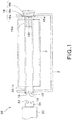
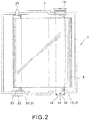
- a ribbon cartridge (assembly of bobbins and a sheet) 1 incorporating a bobbin 10 for a thermal transfer sheet or an image-receiving sheet according to the present invention is described with reference to Fig. 2 .
- the ribbon cartridge 1 includes a supply bobbin 10, a take-up bobbin 20, a case 2 for housing the supply bobbin 10 and the take-up bobbin 20, and an ink ribbon (thermal transfer sheet) 3 having a support layer and an ink layer, provided between the supply bobbin 10 and the take-up bobbin 20.
- the ink ribbon 3 is fixed on the supply bobbin 10 and on the take-up bobbin 20, respectively.
- the take-up bobbin 20 of the ribbon cartridge 1 having such a structure includes a cylindrical bobbin body 21, a gear flange 22 formed integrally with the bobbin body 21 at one side end of the bobbin body 21, and a support shaft 25 formed integrally with the bobbin body 21 at the other side rend of the bobbin body 21.
- the "one side end of the bobbin body 21” means the whole one side end of the bobbin body 21 in an axial direction thereof, and the "other side end of the bobbin body 21” means the whole other side end of the bobbin body 21 in the axial direction.
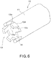
- the gear flange 23 has a plurality of teeth 22a formed in an inner circumferential surface thereof.
- the teeth 22a formed in the inner circumferential surface are engaged with a drive unit 40 of the thermal transfer printer 50 so that the drive unit 40 drives the take-up bobbin 20 in rotation (see Fig. 3 ).
- the bobbin body 21 of the take-up bobbin 20 has a circumferential projection 23 in the vicinity of the gear flange 22. A portion of the bobbin body 21, which lies between the gear flange 22 and the circumferential projection 23, is engaged with the case 2, whereby the take-up bobbin 20 is located in position along the axial direction within the case 2.
- the drive unit 40 of the thermal transfer printer 50 includes a drive shaft 41.
- a drive gear 42 which is engaged with the teeth 22a of the gear flange 22, is formed on an end of the drive shaft 41.
- the supply bobbin 10 (bobbin for a thermal transfer sheet or an image-receiving sheet according to the present invention) of the ribbon cartridge 1 is described in detail with reference to Figs. 1 to 8 .
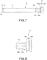
- the supply bobbin 10 includes a cylindrical bobbin body 11 having a gear 12 formed on its one side end.
- the gear 12 has a plurality of teeth 13 and tooth groves 14 formed between the teeth 13.
- the gear 12 is engaged with a brake gear 32 of a brake shaft 31 provided on a brake unit 30 of the thermal transfer printer 50.
- the "one side end of the bobbin body 11" means the whole one side end of the bobbin body 11 in an axial direction thereof, and the "other side end of the bobbin body 11” means the whole other side end of the bobbin body 11 in the axial direction.
- a plurality of engagement grooves 17 are formed in the other side end of the bobbin body 11.
- engagement projections 18e of the flange part 18 are configured to be engaged with the engagement grooves 17.
- the supply bobbin 10 is described in detail with reference to Figs. 4A, 4B to 8 .
- the supply bobbin 10 includes the cylindrical bobbin body 11 having the gear 12 on one side end of the bobbin body 11.
- the gear 12 has the teeth 13 and the tooth grooves 14 formed between the teeth 13.
- Each tooth 13 has a parallelogram shape as a whole with four corners 15a, 15b, 15c and 15d, and four sides 13a, 13b, 13c and 13d (see Figs. 4A and 4B ), when viewed from a lateral surface of the bobbin body 11.
- the expression "when viewed from the lateral side” means that the bobbin body 11 is viewed from the side perpendicular to the axial direction of the bobbin body 11.
- each tooth 13 has a parallelogram shape which has four corners 15a, 15b, 15c and 15d, and the sides 13a, 13b, 13c and 13d: the side 13a being formed between the corners 15a and 15b, the side 13b being formed between the corners 15b and 15c, a side 13c being formed between the corners 15a and 15d, and the side 13d being formed between the corners 15c and 15d.
- the side 13d of the respective sides 13a, 13b, 13c and 13d is a virtual side that does not constitute an outer surface of the gear 12.
- the sides 13a and 13d of the respective sides 13a, 13b, 13c and 13d extend perpendicularly to an axis line of the bobbin body 11. Further, the sides 13b and 13c are inclined with respect to the axis line of the bobbin body 11.
- the brake gear 32 to be engaged with the gear 12 has recessed portions of a shape corresponding to the parallelogram shape of each tooth 13, in order to reliably receive the respective teeth 13 of the gear 12.
- each of the four corners 15a, 15b, 15c and 15d of each tooth 13 has a chamfered curved surface.
- each of the sides 13a, 13b, 13c and 13d of each tooth 13 is curved to be outwardly convex.
- the side 13c has an inwardly facing groove portion 13e formed therein. In this case, due to the formation of the groove portion 13e, the gear 12 and the respective teeth 13 can be more securely engaged with each other.
- each of the four corners 15a, 15b, 15c and 15d of each tooth 13 has a chamfered curved surface, and each of the sides 13a, 13b, 13c and 13d of each tooth 13 is curved to be outwardly convex, the tooth 13 has curved surfaces as a whole. Thus, there is no possibility that an operator who operates the bobbins 10 and 20 is scratched by the supply bobbin 10.
- each tooth 13 of the gear 12 has a parallelogram shape with the four corners 15a, 15b, 15c and 15d, and the brake gear 32 to be engaged with the gear 12 has the recessed portions of a shape corresponding to the parallelogram shape of each tooth 13, the respective teeth 13 of the gear 12 and the recessed portions of the brake gear 32 can be securely engaged with each other.
- the parallelogram shape of each tooth 13 has the sides 13b and 13c that are inclined with respect to the axis line direction of the bobbin body 11, a rotational force in a direction R about the axis line of the bobbin body 11 can be reliably transmitted from the brake gear 32 to the gear 12.
- the thus-constructed bobbin body 11 is disposed coaxially with the brake shaft 31 of the thermal transfer printer, and can reliably brake the bobbin body 11 by the brake shaft 31 through the brake gear 32 and the gear 12.
- the flange part 18 is to be mounted on the other side of the bobbin body 11, and includes a first flange 18a, a second flange 18b, and an engagement portion 18c which is formed between the first flange 18a and the second flange 18b and is engaged with the case 2.
- a cylindrical portion 18d which is to be inserted into the bobbin body 11, is coupled to the first flange 18a.
- engagement projections 18e which are to be engaged with the engagement grooves 17 of the bobbin body 11, are provided on the cylindrical portion 18d of the flange part 18 at positions adjacent to the first flange 18a.
- the cylindrical portion 18d of the flange part 18 is provided with axial ribs 18f whose projecting height is lower than the height of the engagement projections 18e and which extend in the axial direction.
- the axial ribs 18f of the flange part 18 are configured to be engaged with axial grooves (not shown) formed in the inner surface of the bobbin body 11.
- the thus-constructed flange part 18 is formed as a separate member from the bobbin body 1, and is mounted on the bobbin body 11. In this manner, the supply bobbin 10 is constructed.
- the flange part 18 has a built-in RFID for identifying the type of the ink ribbon 3 to be supplied.
- the supply bobbin 10 with the ink ribbon 3 wound thereon, and the take-up bobbin 20 are prepared.
- the ink ribbon 3 is wound on the supply bobbin 10
- the ink ribbon 3 is kept pressed against the supply bobbin 10 by means of a touch roller.
- the supply bobbin 10 and the take-up bobbin 20 are set in the case 2, thereby obtaining the ribbon cartridge (the assembly of bobbins and a sheet) 1 including the case 2, the supply bobbin 10 with the ink ribbon 3 wound thereon, and the take-up bobbin 20.
- the ribbon cartridge 1 is mounted on a mounting unit 50A of the thermal transfer printer 50.
- the take-up bobbin 20 of the ribbon cartridge 1 aligns coaxially with the drive shaft 41 of the drive unit 40 of the thermal transfer printer 50, while the supply bobbin 10 aligns coaxially with the brake shaft 31 of the brake shaft 30 of the thermal transfer printer.
- the drive unit 40 is pressed against the take-up bobbin 20, whereby the drive gear 42 of the drive unit 40 is engaged with the gear flange 22 (the teeth 22a formed in the inner circumferential surface) of the take-up bobbin 20.
- the brake unit 30 is pressed against the supply bobbin 10, whereby the brake gear 32 formed on the brake shaft 31 of the brake unit 30 is engaged with the gear 12 of the supply bobbin 10.
- the brake gear 32 of the brake unit 30 and the gear 12 of the supply bobbin 10 can be engaged with each other easily and simply, only by pressing the brake unit 30 against the supply bobbin 10 so that any of the brake gear 32 of the brake unit 30 and the gear 12 of the supply bobbin 10 is slightly rotated.
- the take-up bobbin 20 is driven by the drive unit 40, and the supply bobbin 10 is braked by a brake (not shown) built in the brake unit 30.
- a brake (not shown) built in the brake unit 30.
- the ink ribbon 3 wound on the supply bobbin 10 is supplied.
- the ink ribbon 3, which extends between the supply bobbin 10 and the take-up bobbin 20, is heated by a thermal head (not shown), whereby the ink of the ink ribbon 3 is transferred onto an image-receiving sheet (not shown). A thermal transfer operation is performed in this manner.
- the brake gear 32 of the brake unit 30 of the thermal transfer printer 50 can be directly engaged with the gear 12.
- the driving force in the rotational direction from the brake shaft 31 of the brake unit 30 can be directly transmitted to the bobbin body 11.
- the bobbin body 11 Accordingly, there is no need to provide the bobbin body 11 with a flange that is engaged with the brake shaft 31, resulting in reduction of the number of components. Furthermore, there is no need to provide driving irregularities to be engaged with the brake shaft 31 of the brake unit 30, on the outer surface of the bobbin body 11.
- the outer surface of the bobbin body 11 can therefore be a smooth surface. This can avoid scratching on a rubber touch roller which is used to wind the ink ribbon 3 on the supply bobbin 10.
- the gear 12 and the brake gear 32 of the brake unit 30 can be engaged with each other easily and simply, only by pressing the brake unit 30 against the gear 12.
- the flange part 18 is mounted on the other side end of the bobbin body 11 of the supply bobbin 10.
- the present invention is not limited thereto.
- the gear 12 which includes the teeth 13 and the tooth grooves 14 formed between the teeth 13, is formed on the one side end of the bobbin body 11.
- the supply bobbin 10 consists solely of the bobbin body 11 and has no flange part, the number of constituent components can be further reduced.
- the ink ribbon (thermal transfer sheet) 3 is wound on the supply bobbin 10 and the take-up bobbin 20.
Applications Claiming Priority (2)
| Application Number | Priority Date | Filing Date | Title |
|---|---|---|---|
| JP2015233382A JP6395057B2 (ja) | 2015-11-30 | 2015-11-30 | 熱転写シートまたは受像シート用ボビン、ボビンとシートの組合体および熱転写プリンタ |
| PCT/JP2016/085450 WO2017094735A1 (ja) | 2015-11-30 | 2016-11-29 | 熱転写シートまたは受像シート用ボビン、ボビンとシートの組合体および熱転写プリンタ |
Publications (3)
| Publication Number | Publication Date |
|---|---|
| EP3357848A1 EP3357848A1 (en) | 2018-08-08 |
| EP3357848A4 EP3357848A4 (en) | 2019-06-19 |
| EP3357848B1 true EP3357848B1 (en) | 2020-11-18 |
Family
ID=58796934
Family Applications (1)
| Application Number | Title | Priority Date | Filing Date |
|---|---|---|---|
| EP16870672.9A Active EP3357848B1 (en) | 2015-11-30 | 2016-11-29 | Bobbin for thermal transfer sheet or image receiving sheet, combined body of bobbin and sheet, and thermal transfer printer |
Country Status (7)
| Country | Link |
|---|---|
| US (1) | US10486434B2 (ja) |
| EP (1) | EP3357848B1 (ja) |
| JP (1) | JP6395057B2 (ja) |
| KR (1) | KR102134331B1 (ja) |
| CN (1) | CN108290701B (ja) |
| MY (1) | MY176097A (ja) |
| WO (1) | WO2017094735A1 (ja) |
Family Cites Families (22)
| Publication number | Priority date | Publication date | Assignee | Title |
|---|---|---|---|---|
| JPS61277540A (ja) * | 1985-06-03 | 1986-12-08 | Matsushita Electric Ind Co Ltd | 定トルク機構 |
| JP2569031B2 (ja) * | 1987-01-09 | 1997-01-08 | 株式会社日立製作所 | インク紙カセツト |
| US4892425A (en) | 1987-01-09 | 1990-01-09 | Hitachi, Ltd. | Thermal transfer recording apparatus and ink sheet cassette therefor |
| JPH07100555B2 (ja) * | 1989-06-28 | 1995-11-01 | 株式会社テック | ウェブ保持装置 |
| DE3909979A1 (de) * | 1989-03-25 | 1990-09-27 | Zimmermann Jos Gmbh & Co Kg | Wickeltraeger zur aufnahme von garnen sowie verfahren zu seiner anwendung |
| KR930002400Y1 (ko) * | 1990-12-17 | 1993-05-10 | 주식회사 에스케이씨 | 필름(Film) 권취용 보빈 아답터(ADADTER) |
| JPH0920043A (ja) * | 1995-07-06 | 1997-01-21 | Graphtec Corp | 記録用ロール取付構造 |
| JP3334516B2 (ja) * | 1996-10-31 | 2002-10-15 | ミノルタ株式会社 | インクフィルムカセットおよびインクフィルムカセットに用いられるリール |
| US6457885B1 (en) | 1996-10-31 | 2002-10-01 | Minolta Co., Ltd. | Thermal transfer recording apparatus, ink film cassette and ink film reel |
| JPH10252767A (ja) * | 1997-03-11 | 1998-09-22 | Fuji Xerox Co Ltd | 駆動力伝達装置 |
| JP2001122523A (ja) * | 1999-10-22 | 2001-05-08 | Dainippon Printing Co Ltd | 巻枠及びフランジ |
| JP2001150775A (ja) | 1999-11-25 | 2001-06-05 | Dainippon Printing Co Ltd | ボビン |
| JP2002046945A (ja) * | 2000-08-01 | 2002-02-12 | Dainippon Printing Co Ltd | 巻 枠 |
| JP2002132091A (ja) * | 2000-10-23 | 2002-05-09 | Seiko Epson Corp | 画像形成装置 |
| JP2004291392A (ja) * | 2003-03-27 | 2004-10-21 | Pilot Corporation | リボンカセット |
| JP4595090B2 (ja) * | 2005-05-12 | 2010-12-08 | ソニー株式会社 | インクリボンカセット |
| KR200409328Y1 (ko) * | 2005-11-28 | 2006-02-22 | 송영만 | 보빈 |
| JP4411272B2 (ja) * | 2005-12-21 | 2010-02-10 | Necアクセステクニカ株式会社 | フィルムシャフト機構、熱転写記録装置およびフィルムシャフト |
| JP6247011B2 (ja) * | 2013-03-29 | 2017-12-13 | キヤノンファインテックニスカ株式会社 | 印刷装置 |
| CN204280784U (zh) * | 2014-10-17 | 2015-04-22 | 汕头市远东轻化装备有限公司 | 一种气胀夹紧夹头 |
| JP6297514B2 (ja) * | 2015-03-19 | 2018-03-20 | セイコーエプソン株式会社 | テープカートリッジ |
| JP6361678B2 (ja) * | 2016-03-17 | 2018-07-25 | 住友電気工業株式会社 | ボビン |
-
2015
- 2015-11-30 JP JP2015233382A patent/JP6395057B2/ja active Active
-
2016
- 2016-11-29 MY MYPI2018702020A patent/MY176097A/en unknown
- 2016-11-29 KR KR1020187015042A patent/KR102134331B1/ko active IP Right Grant
- 2016-11-29 CN CN201680068328.4A patent/CN108290701B/zh active Active
- 2016-11-29 WO PCT/JP2016/085450 patent/WO2017094735A1/ja active Application Filing
- 2016-11-29 US US15/773,252 patent/US10486434B2/en active Active
- 2016-11-29 EP EP16870672.9A patent/EP3357848B1/en active Active
Non-Patent Citations (1)
| Title |
|---|
| None * |
Also Published As
| Publication number | Publication date |
|---|---|
| JP6395057B2 (ja) | 2018-09-26 |
| US10486434B2 (en) | 2019-11-26 |
| KR20180089411A (ko) | 2018-08-08 |
| CN108290701B (zh) | 2019-12-31 |
| JP2017100821A (ja) | 2017-06-08 |
| US20180326742A1 (en) | 2018-11-15 |
| EP3357848A1 (en) | 2018-08-08 |
| EP3357848A4 (en) | 2019-06-19 |
| CN108290701A (zh) | 2018-07-17 |
| WO2017094735A1 (ja) | 2017-06-08 |
| KR102134331B1 (ko) | 2020-07-16 |
| MY176097A (en) | 2020-07-24 |
Similar Documents
| Publication | Publication Date | Title |
|---|---|---|
| JP4582040B2 (ja) | テープ供給カートリッジ | |
| JP3700692B2 (ja) | リボンカセット | |
| JP6297514B2 (ja) | テープカートリッジ | |
| EP3150534B1 (en) | Bobbin for thermal transfer sheet or image receiving sheet, bobbin/sheet combination, and thermal transfer printer | |
| EP3378819B1 (en) | Bobbin for thermal transfer sheet or image-receiving sheet, bobbin and sheet combination, and thermal transfer printer | |
| JP2550191B2 (ja) | 熱転写フィルム用カセットおよびこれに用いるインクフィルム | |
| EP3357848B1 (en) | Bobbin for thermal transfer sheet or image receiving sheet, combined body of bobbin and sheet, and thermal transfer printer | |
| EP3932682A1 (en) | Cassette | |
| JP5978116B2 (ja) | インクリボンカートリッジおよび印刷装置 | |
| US20060027698A1 (en) | Spool | |
| JP4595092B2 (ja) | インクリボンスプール | |
| JP6452869B2 (ja) | テープカートリッジ | |
| JP6498805B2 (ja) | テープカートリッジ | |
| JPH02116584A (ja) | 熱転写型印字用リボンカセット | |
| JPS61279578A (ja) | 印字装置のリボンカセツト | |
| JPS62170377A (ja) | リボンカ−トリツジ | |
| JPH04104463U (ja) | インクリボンカセツト |
Legal Events
| Date | Code | Title | Description |
|---|---|---|---|
| STAA | Information on the status of an ep patent application or granted ep patent |
Free format text: STATUS: THE INTERNATIONAL PUBLICATION HAS BEEN MADE |
|
| PUAI | Public reference made under article 153(3) epc to a published international application that has entered the european phase |
Free format text: ORIGINAL CODE: 0009012 |
|
| STAA | Information on the status of an ep patent application or granted ep patent |
Free format text: STATUS: REQUEST FOR EXAMINATION WAS MADE |
|
| 17P | Request for examination filed |
Effective date: 20180504 |
|
| AK | Designated contracting states |
Kind code of ref document: A1 Designated state(s): AL AT BE BG CH CY CZ DE DK EE ES FI FR GB GR HR HU IE IS IT LI LT LU LV MC MK MT NL NO PL PT RO RS SE SI SK SM TR |
|
| AX | Request for extension of the european patent |
Extension state: BA ME |
|
| DAV | Request for validation of the european patent (deleted) | ||
| DAX | Request for extension of the european patent (deleted) | ||
| A4 | Supplementary search report drawn up and despatched |
Effective date: 20190520 |
|
| RIC1 | Information provided on ipc code assigned before grant |
Ipc: B65H 75/18 20060101AFI20190514BHEP Ipc: B41J 2/325 20060101ALI20190514BHEP Ipc: B41J 33/22 20060101ALI20190514BHEP Ipc: B41J 17/24 20060101ALI20190514BHEP Ipc: B65H 75/10 20060101ALI20190514BHEP Ipc: B65H 75/30 20060101ALI20190514BHEP |
|
| GRAP | Despatch of communication of intention to grant a patent |
Free format text: ORIGINAL CODE: EPIDOSNIGR1 |
|
| STAA | Information on the status of an ep patent application or granted ep patent |
Free format text: STATUS: GRANT OF PATENT IS INTENDED |
|
| INTG | Intention to grant announced |
Effective date: 20200622 |
|
| GRAS | Grant fee paid |
Free format text: ORIGINAL CODE: EPIDOSNIGR3 |
|
| GRAA | (expected) grant |
Free format text: ORIGINAL CODE: 0009210 |
|
| STAA | Information on the status of an ep patent application or granted ep patent |
Free format text: STATUS: THE PATENT HAS BEEN GRANTED |
|
| AK | Designated contracting states |
Kind code of ref document: B1 Designated state(s): AL AT BE BG CH CY CZ DE DK EE ES FI FR GB GR HR HU IE IS IT LI LT LU LV MC MK MT NL NO PL PT RO RS SE SI SK SM TR |
|
| REG | Reference to a national code |
Ref country code: GB Ref legal event code: FG4D |
|
| REG | Reference to a national code |
Ref country code: CH Ref legal event code: EP |
|
| REG | Reference to a national code |
Ref country code: IE Ref legal event code: FG4D |
|
| REG | Reference to a national code |
Ref country code: DE Ref legal event code: R096 Ref document number: 602016048320 Country of ref document: DE |
|
| REG | Reference to a national code |
Ref country code: AT Ref legal event code: REF Ref document number: 1335546 Country of ref document: AT Kind code of ref document: T Effective date: 20201215 |
|
| REG | Reference to a national code |
Ref country code: NL Ref legal event code: FP |
|
| REG | Reference to a national code |
Ref country code: AT Ref legal event code: MK05 Ref document number: 1335546 Country of ref document: AT Kind code of ref document: T Effective date: 20201118 |
|
| PG25 | Lapsed in a contracting state [announced via postgrant information from national office to epo] |
Ref country code: GR Free format text: LAPSE BECAUSE OF FAILURE TO SUBMIT A TRANSLATION OF THE DESCRIPTION OR TO PAY THE FEE WITHIN THE PRESCRIBED TIME-LIMIT Effective date: 20210219 Ref country code: FI Free format text: LAPSE BECAUSE OF FAILURE TO SUBMIT A TRANSLATION OF THE DESCRIPTION OR TO PAY THE FEE WITHIN THE PRESCRIBED TIME-LIMIT Effective date: 20201118 Ref country code: RS Free format text: LAPSE BECAUSE OF FAILURE TO SUBMIT A TRANSLATION OF THE DESCRIPTION OR TO PAY THE FEE WITHIN THE PRESCRIBED TIME-LIMIT Effective date: 20201118 Ref country code: PT Free format text: LAPSE BECAUSE OF FAILURE TO SUBMIT A TRANSLATION OF THE DESCRIPTION OR TO PAY THE FEE WITHIN THE PRESCRIBED TIME-LIMIT Effective date: 20210318 Ref country code: NO Free format text: LAPSE BECAUSE OF FAILURE TO SUBMIT A TRANSLATION OF THE DESCRIPTION OR TO PAY THE FEE WITHIN THE PRESCRIBED TIME-LIMIT Effective date: 20210218 |
|
| PG25 | Lapsed in a contracting state [announced via postgrant information from national office to epo] |
Ref country code: AT Free format text: LAPSE BECAUSE OF FAILURE TO SUBMIT A TRANSLATION OF THE DESCRIPTION OR TO PAY THE FEE WITHIN THE PRESCRIBED TIME-LIMIT Effective date: 20201118 Ref country code: LV Free format text: LAPSE BECAUSE OF FAILURE TO SUBMIT A TRANSLATION OF THE DESCRIPTION OR TO PAY THE FEE WITHIN THE PRESCRIBED TIME-LIMIT Effective date: 20201118 Ref country code: PL Free format text: LAPSE BECAUSE OF FAILURE TO SUBMIT A TRANSLATION OF THE DESCRIPTION OR TO PAY THE FEE WITHIN THE PRESCRIBED TIME-LIMIT Effective date: 20201118 Ref country code: IS Free format text: LAPSE BECAUSE OF FAILURE TO SUBMIT A TRANSLATION OF THE DESCRIPTION OR TO PAY THE FEE WITHIN THE PRESCRIBED TIME-LIMIT Effective date: 20210318 Ref country code: BG Free format text: LAPSE BECAUSE OF FAILURE TO SUBMIT A TRANSLATION OF THE DESCRIPTION OR TO PAY THE FEE WITHIN THE PRESCRIBED TIME-LIMIT Effective date: 20210218 Ref country code: SE Free format text: LAPSE BECAUSE OF FAILURE TO SUBMIT A TRANSLATION OF THE DESCRIPTION OR TO PAY THE FEE WITHIN THE PRESCRIBED TIME-LIMIT Effective date: 20201118 |
|
| REG | Reference to a national code |
Ref country code: DE Ref legal event code: R119 Ref document number: 602016048320 Country of ref document: DE |
|
| REG | Reference to a national code |
Ref country code: LT Ref legal event code: MG9D |
|
| PG25 | Lapsed in a contracting state [announced via postgrant information from national office to epo] |
Ref country code: HR Free format text: LAPSE BECAUSE OF FAILURE TO SUBMIT A TRANSLATION OF THE DESCRIPTION OR TO PAY THE FEE WITHIN THE PRESCRIBED TIME-LIMIT Effective date: 20201118 |
|
| REG | Reference to a national code |
Ref country code: CH Ref legal event code: PL |
|
| PG25 | Lapsed in a contracting state [announced via postgrant information from national office to epo] |
Ref country code: SM Free format text: LAPSE BECAUSE OF FAILURE TO SUBMIT A TRANSLATION OF THE DESCRIPTION OR TO PAY THE FEE WITHIN THE PRESCRIBED TIME-LIMIT Effective date: 20201118 Ref country code: LT Free format text: LAPSE BECAUSE OF FAILURE TO SUBMIT A TRANSLATION OF THE DESCRIPTION OR TO PAY THE FEE WITHIN THE PRESCRIBED TIME-LIMIT Effective date: 20201118 Ref country code: LU Free format text: LAPSE BECAUSE OF NON-PAYMENT OF DUE FEES Effective date: 20201129 Ref country code: CZ Free format text: LAPSE BECAUSE OF FAILURE TO SUBMIT A TRANSLATION OF THE DESCRIPTION OR TO PAY THE FEE WITHIN THE PRESCRIBED TIME-LIMIT Effective date: 20201118 Ref country code: EE Free format text: LAPSE BECAUSE OF FAILURE TO SUBMIT A TRANSLATION OF THE DESCRIPTION OR TO PAY THE FEE WITHIN THE PRESCRIBED TIME-LIMIT Effective date: 20201118 Ref country code: SK Free format text: LAPSE BECAUSE OF FAILURE TO SUBMIT A TRANSLATION OF THE DESCRIPTION OR TO PAY THE FEE WITHIN THE PRESCRIBED TIME-LIMIT Effective date: 20201118 Ref country code: RO Free format text: LAPSE BECAUSE OF FAILURE TO SUBMIT A TRANSLATION OF THE DESCRIPTION OR TO PAY THE FEE WITHIN THE PRESCRIBED TIME-LIMIT Effective date: 20201118 |
|
| REG | Reference to a national code |
Ref country code: BE Ref legal event code: MM Effective date: 20201130 |
|
| PG25 | Lapsed in a contracting state [announced via postgrant information from national office to epo] |
Ref country code: DK Free format text: LAPSE BECAUSE OF FAILURE TO SUBMIT A TRANSLATION OF THE DESCRIPTION OR TO PAY THE FEE WITHIN THE PRESCRIBED TIME-LIMIT Effective date: 20201118 Ref country code: CH Free format text: LAPSE BECAUSE OF NON-PAYMENT OF DUE FEES Effective date: 20201130 Ref country code: MC Free format text: LAPSE BECAUSE OF FAILURE TO SUBMIT A TRANSLATION OF THE DESCRIPTION OR TO PAY THE FEE WITHIN THE PRESCRIBED TIME-LIMIT Effective date: 20201118 Ref country code: LI Free format text: LAPSE BECAUSE OF NON-PAYMENT OF DUE FEES Effective date: 20201130 |
|
| REG | Reference to a national code |
Ref country code: IE Ref legal event code: MM4A |
|
| PLBE | No opposition filed within time limit |
Free format text: ORIGINAL CODE: 0009261 |
|
| STAA | Information on the status of an ep patent application or granted ep patent |
Free format text: STATUS: NO OPPOSITION FILED WITHIN TIME LIMIT |
|
| 26N | No opposition filed |
Effective date: 20210819 |
|
| GBPC | Gb: european patent ceased through non-payment of renewal fee |
Effective date: 20210218 |
|
| PG25 | Lapsed in a contracting state [announced via postgrant information from national office to epo] |
Ref country code: IT Free format text: LAPSE BECAUSE OF FAILURE TO SUBMIT A TRANSLATION OF THE DESCRIPTION OR TO PAY THE FEE WITHIN THE PRESCRIBED TIME-LIMIT Effective date: 20201118 Ref country code: AL Free format text: LAPSE BECAUSE OF FAILURE TO SUBMIT A TRANSLATION OF THE DESCRIPTION OR TO PAY THE FEE WITHIN THE PRESCRIBED TIME-LIMIT Effective date: 20201118 Ref country code: IE Free format text: LAPSE BECAUSE OF NON-PAYMENT OF DUE FEES Effective date: 20201129 |
|
| PG25 | Lapsed in a contracting state [announced via postgrant information from national office to epo] |
Ref country code: SI Free format text: LAPSE BECAUSE OF FAILURE TO SUBMIT A TRANSLATION OF THE DESCRIPTION OR TO PAY THE FEE WITHIN THE PRESCRIBED TIME-LIMIT Effective date: 20201118 Ref country code: DE Free format text: LAPSE BECAUSE OF NON-PAYMENT OF DUE FEES Effective date: 20210601 |
|
| PG25 | Lapsed in a contracting state [announced via postgrant information from national office to epo] |
Ref country code: GB Free format text: LAPSE BECAUSE OF NON-PAYMENT OF DUE FEES Effective date: 20210218 Ref country code: ES Free format text: LAPSE BECAUSE OF FAILURE TO SUBMIT A TRANSLATION OF THE DESCRIPTION OR TO PAY THE FEE WITHIN THE PRESCRIBED TIME-LIMIT Effective date: 20201118 |
|
| PG25 | Lapsed in a contracting state [announced via postgrant information from national office to epo] |
Ref country code: IS Free format text: LAPSE BECAUSE OF FAILURE TO SUBMIT A TRANSLATION OF THE DESCRIPTION OR TO PAY THE FEE WITHIN THE PRESCRIBED TIME-LIMIT Effective date: 20210318 Ref country code: TR Free format text: LAPSE BECAUSE OF FAILURE TO SUBMIT A TRANSLATION OF THE DESCRIPTION OR TO PAY THE FEE WITHIN THE PRESCRIBED TIME-LIMIT Effective date: 20201118 Ref country code: MT Free format text: LAPSE BECAUSE OF FAILURE TO SUBMIT A TRANSLATION OF THE DESCRIPTION OR TO PAY THE FEE WITHIN THE PRESCRIBED TIME-LIMIT Effective date: 20201118 Ref country code: CY Free format text: LAPSE BECAUSE OF FAILURE TO SUBMIT A TRANSLATION OF THE DESCRIPTION OR TO PAY THE FEE WITHIN THE PRESCRIBED TIME-LIMIT Effective date: 20201118 |
|
| PG25 | Lapsed in a contracting state [announced via postgrant information from national office to epo] |
Ref country code: MK Free format text: LAPSE BECAUSE OF FAILURE TO SUBMIT A TRANSLATION OF THE DESCRIPTION OR TO PAY THE FEE WITHIN THE PRESCRIBED TIME-LIMIT Effective date: 20201118 |
|
| PG25 | Lapsed in a contracting state [announced via postgrant information from national office to epo] |
Ref country code: BE Free format text: LAPSE BECAUSE OF NON-PAYMENT OF DUE FEES Effective date: 20201130 |
|
| P01 | Opt-out of the competence of the unified patent court (upc) registered |
Effective date: 20230524 |
|
| PGFP | Annual fee paid to national office [announced via postgrant information from national office to epo] |
Ref country code: NL Payment date: 20231120 Year of fee payment: 8 |
|
| PGFP | Annual fee paid to national office [announced via postgrant information from national office to epo] |
Ref country code: FR Payment date: 20231120 Year of fee payment: 8 |