EP3355998B1 - Trampolin - Google Patents
Trampolin Download PDFInfo
- Publication number
- EP3355998B1 EP3355998B1 EP16774950.6A EP16774950A EP3355998B1 EP 3355998 B1 EP3355998 B1 EP 3355998B1 EP 16774950 A EP16774950 A EP 16774950A EP 3355998 B1 EP3355998 B1 EP 3355998B1
- Authority
- EP
- European Patent Office
- Prior art keywords
- guide
- frame
- inner piece
- trampoline according
- trampoline
- Prior art date
- Legal status (The legal status is an assumption and is not a legal conclusion. Google has not performed a legal analysis and makes no representation as to the accuracy of the status listed.)
- Active
Links
- 230000002093 peripheral effect Effects 0.000 claims description 6
- 230000009191 jumping Effects 0.000 description 13
- 239000000725 suspension Substances 0.000 description 10
- 238000010276 construction Methods 0.000 description 6
- 239000002184 metal Substances 0.000 description 4
- 238000003780 insertion Methods 0.000 description 3
- 230000037431 insertion Effects 0.000 description 3
- 238000004519 manufacturing process Methods 0.000 description 3
- 239000004033 plastic Substances 0.000 description 3
- 208000027418 Wounds and injury Diseases 0.000 description 2
- 230000006378 damage Effects 0.000 description 2
- 238000013461 design Methods 0.000 description 2
- 208000014674 injury Diseases 0.000 description 2
- 230000003993 interaction Effects 0.000 description 2
- 238000012549 training Methods 0.000 description 2
- 101100495270 Caenorhabditis elegans cdc-26 gene Proteins 0.000 description 1
- 229910000831 Steel Inorganic materials 0.000 description 1
- 230000001133 acceleration Effects 0.000 description 1
- 238000011161 development Methods 0.000 description 1
- 230000000694 effects Effects 0.000 description 1
- 238000012423 maintenance Methods 0.000 description 1
- 239000000463 material Substances 0.000 description 1
- 230000003387 muscular Effects 0.000 description 1
- 230000000737 periodic effect Effects 0.000 description 1
- 238000000554 physical therapy Methods 0.000 description 1
- 229910001220 stainless steel Inorganic materials 0.000 description 1
- 239000010935 stainless steel Substances 0.000 description 1
- 239000010959 steel Substances 0.000 description 1
- 230000003313 weakening effect Effects 0.000 description 1
Images


Classifications
-
- A—HUMAN NECESSITIES
- A63—SPORTS; GAMES; AMUSEMENTS
- A63B—APPARATUS FOR PHYSICAL TRAINING, GYMNASTICS, SWIMMING, CLIMBING, OR FENCING; BALL GAMES; TRAINING EQUIPMENT
- A63B5/00—Apparatus for jumping
- A63B5/11—Trampolines
-
- A—HUMAN NECESSITIES
- A63—SPORTS; GAMES; AMUSEMENTS
- A63B—APPARATUS FOR PHYSICAL TRAINING, GYMNASTICS, SWIMMING, CLIMBING, OR FENCING; BALL GAMES; TRAINING EQUIPMENT
- A63B21/00—Exercising apparatus for developing or strengthening the muscles or joints of the body by working against a counterforce, with or without measuring devices
- A63B21/40—Interfaces with the user related to strength training; Details thereof
- A63B21/4027—Specific exercise interfaces
- A63B21/4033—Handles, pedals, bars or platforms
- A63B21/4035—Handles, pedals, bars or platforms for operation by hand
-
- F—MECHANICAL ENGINEERING; LIGHTING; HEATING; WEAPONS; BLASTING
- F16—ENGINEERING ELEMENTS AND UNITS; GENERAL MEASURES FOR PRODUCING AND MAINTAINING EFFECTIVE FUNCTIONING OF MACHINES OR INSTALLATIONS; THERMAL INSULATION IN GENERAL
- F16B—DEVICES FOR FASTENING OR SECURING CONSTRUCTIONAL ELEMENTS OR MACHINE PARTS TOGETHER, e.g. NAILS, BOLTS, CIRCLIPS, CLAMPS, CLIPS OR WEDGES; JOINTS OR JOINTING
- F16B2/00—Friction-grip releasable fastenings
- F16B2/02—Clamps, i.e. with gripping action effected by positive means other than the inherent resistance to deformation of the material of the fastening
- F16B2/06—Clamps, i.e. with gripping action effected by positive means other than the inherent resistance to deformation of the material of the fastening external, i.e. with contracting action
- F16B2/065—Clamps, i.e. with gripping action effected by positive means other than the inherent resistance to deformation of the material of the fastening external, i.e. with contracting action using screw-thread elements
-
- F—MECHANICAL ENGINEERING; LIGHTING; HEATING; WEAPONS; BLASTING
- F16—ENGINEERING ELEMENTS AND UNITS; GENERAL MEASURES FOR PRODUCING AND MAINTAINING EFFECTIVE FUNCTIONING OF MACHINES OR INSTALLATIONS; THERMAL INSULATION IN GENERAL
- F16B—DEVICES FOR FASTENING OR SECURING CONSTRUCTIONAL ELEMENTS OR MACHINE PARTS TOGETHER, e.g. NAILS, BOLTS, CIRCLIPS, CLAMPS, CLIPS OR WEDGES; JOINTS OR JOINTING
- F16B2/00—Friction-grip releasable fastenings
- F16B2/02—Clamps, i.e. with gripping action effected by positive means other than the inherent resistance to deformation of the material of the fastening
- F16B2/06—Clamps, i.e. with gripping action effected by positive means other than the inherent resistance to deformation of the material of the fastening external, i.e. with contracting action
- F16B2/12—Clamps, i.e. with gripping action effected by positive means other than the inherent resistance to deformation of the material of the fastening external, i.e. with contracting action using sliding jaws
-
- F—MECHANICAL ENGINEERING; LIGHTING; HEATING; WEAPONS; BLASTING
- F16—ENGINEERING ELEMENTS AND UNITS; GENERAL MEASURES FOR PRODUCING AND MAINTAINING EFFECTIVE FUNCTIONING OF MACHINES OR INSTALLATIONS; THERMAL INSULATION IN GENERAL
- F16B—DEVICES FOR FASTENING OR SECURING CONSTRUCTIONAL ELEMENTS OR MACHINE PARTS TOGETHER, e.g. NAILS, BOLTS, CIRCLIPS, CLAMPS, CLIPS OR WEDGES; JOINTS OR JOINTING
- F16B2/00—Friction-grip releasable fastenings
- F16B2/02—Clamps, i.e. with gripping action effected by positive means other than the inherent resistance to deformation of the material of the fastening
- F16B2/18—Clamps, i.e. with gripping action effected by positive means other than the inherent resistance to deformation of the material of the fastening using cams, levers, eccentrics, or toggles
- F16B2/185—Clamps, i.e. with gripping action effected by positive means other than the inherent resistance to deformation of the material of the fastening using cams, levers, eccentrics, or toggles using levers
-
- F—MECHANICAL ENGINEERING; LIGHTING; HEATING; WEAPONS; BLASTING
- F16—ENGINEERING ELEMENTS AND UNITS; GENERAL MEASURES FOR PRODUCING AND MAINTAINING EFFECTIVE FUNCTIONING OF MACHINES OR INSTALLATIONS; THERMAL INSULATION IN GENERAL
- F16B—DEVICES FOR FASTENING OR SECURING CONSTRUCTIONAL ELEMENTS OR MACHINE PARTS TOGETHER, e.g. NAILS, BOLTS, CIRCLIPS, CLAMPS, CLIPS OR WEDGES; JOINTS OR JOINTING
- F16B7/00—Connections of rods or tubes, e.g. of non-circular section, mutually, including resilient connections
- F16B7/04—Clamping or clipping connections
- F16B7/044—Clamping or clipping connections for rods or tubes being in angled relationship
- F16B7/0446—Clamping or clipping connections for rods or tubes being in angled relationship for tubes using the innerside thereof
- F16B7/0453—Clamping or clipping connections for rods or tubes being in angled relationship for tubes using the innerside thereof the tubes being drawn towards each other
-
- F—MECHANICAL ENGINEERING; LIGHTING; HEATING; WEAPONS; BLASTING
- F16—ENGINEERING ELEMENTS AND UNITS; GENERAL MEASURES FOR PRODUCING AND MAINTAINING EFFECTIVE FUNCTIONING OF MACHINES OR INSTALLATIONS; THERMAL INSULATION IN GENERAL
- F16B—DEVICES FOR FASTENING OR SECURING CONSTRUCTIONAL ELEMENTS OR MACHINE PARTS TOGETHER, e.g. NAILS, BOLTS, CIRCLIPS, CLAMPS, CLIPS OR WEDGES; JOINTS OR JOINTING
- F16B7/00—Connections of rods or tubes, e.g. of non-circular section, mutually, including resilient connections
- F16B7/10—Telescoping systems
- F16B7/14—Telescoping systems locking in intermediate non-discrete positions
- F16B7/1454—Telescoping systems locking in intermediate non-discrete positions with a clamp locking the telescoping members by swinging a handle provided with a locking cam
-
- F—MECHANICAL ENGINEERING; LIGHTING; HEATING; WEAPONS; BLASTING
- F16—ENGINEERING ELEMENTS AND UNITS; GENERAL MEASURES FOR PRODUCING AND MAINTAINING EFFECTIVE FUNCTIONING OF MACHINES OR INSTALLATIONS; THERMAL INSULATION IN GENERAL
- F16B—DEVICES FOR FASTENING OR SECURING CONSTRUCTIONAL ELEMENTS OR MACHINE PARTS TOGETHER, e.g. NAILS, BOLTS, CIRCLIPS, CLAMPS, CLIPS OR WEDGES; JOINTS OR JOINTING
- F16B7/00—Connections of rods or tubes, e.g. of non-circular section, mutually, including resilient connections
- F16B7/10—Telescoping systems
- F16B7/14—Telescoping systems locking in intermediate non-discrete positions
- F16B7/1472—Telescoping systems locking in intermediate non-discrete positions with a clamping screw perpendicular to the axis of the telescoping members
-
- A—HUMAN NECESSITIES
- A63—SPORTS; GAMES; AMUSEMENTS
- A63B—APPARATUS FOR PHYSICAL TRAINING, GYMNASTICS, SWIMMING, CLIMBING, OR FENCING; BALL GAMES; TRAINING EQUIPMENT
- A63B21/00—Exercising apparatus for developing or strengthening the muscles or joints of the body by working against a counterforce, with or without measuring devices
- A63B21/02—Exercising apparatus for developing or strengthening the muscles or joints of the body by working against a counterforce, with or without measuring devices using resilient force-resisters
- A63B21/023—Wound springs
-
- A—HUMAN NECESSITIES
- A63—SPORTS; GAMES; AMUSEMENTS
- A63B—APPARATUS FOR PHYSICAL TRAINING, GYMNASTICS, SWIMMING, CLIMBING, OR FENCING; BALL GAMES; TRAINING EQUIPMENT
- A63B21/00—Exercising apparatus for developing or strengthening the muscles or joints of the body by working against a counterforce, with or without measuring devices
- A63B21/02—Exercising apparatus for developing or strengthening the muscles or joints of the body by working against a counterforce, with or without measuring devices using resilient force-resisters
- A63B21/055—Exercising apparatus for developing or strengthening the muscles or joints of the body by working against a counterforce, with or without measuring devices using resilient force-resisters extension element type
- A63B21/0552—Elastic ropes or bands
-
- A—HUMAN NECESSITIES
- A63—SPORTS; GAMES; AMUSEMENTS
- A63B—APPARATUS FOR PHYSICAL TRAINING, GYMNASTICS, SWIMMING, CLIMBING, OR FENCING; BALL GAMES; TRAINING EQUIPMENT
- A63B2225/00—Miscellaneous features of sport apparatus, devices or equipment
- A63B2225/09—Adjustable dimensions
- A63B2225/093—Height
-
- A—HUMAN NECESSITIES
- A63—SPORTS; GAMES; AMUSEMENTS
- A63B—APPARATUS FOR PHYSICAL TRAINING, GYMNASTICS, SWIMMING, CLIMBING, OR FENCING; BALL GAMES; TRAINING EQUIPMENT
- A63B2225/00—Miscellaneous features of sport apparatus, devices or equipment
- A63B2225/68—Miscellaneous features of sport apparatus, devices or equipment with article holders
- A63B2225/685—Miscellaneous features of sport apparatus, devices or equipment with article holders for electronic devices, e.g. phone, PDA, GPS device, notebook
Definitions
- the invention relates to a trampoline with the features of patent claim 1.
- the invention is particularly aimed at so-called mini-trampolines, which are also called fitness trampolines. These are smaller trampolines with a maximum diameter of 2 to 3 meters that are used in physiotherapy and fitness.
- the jumping mat is attached to the frame via spiral springs.
- the jumping bed has, for example, a bracket or an eyelet as a receiving device, which is attached to the jumping bed by means of a loop and into which a spiral spring engages.
- the spiral spring is hooked into the frame on the other side.
- a trampoline with a spring suspension provides significant acceleration forces.
- One or more elastic rope rings or (open) ropes are used with the bungee cord suspension, which connect the jumping mat to the frame.
- the receiving device can be designed as a hook element into which a suspension is hung in each case.
- a loop through which a rope is pulled that connects the jumping mat to the frame can also be considered.
- the greater elasticity of such a rubber cable suspension ensures that the body brakes "softer" and in this respect not only protects the joints, but also lengthens the muscular stress and relief phases when jumping, which has advantageous training effects.
- the invention is directed both to trampolines with spring suspensions and to trampolines in which the suspension is designed as an elastic rope or elastic rope ring.
- the invention can be used with any type of trampoline, regardless of the type of suspension of the jumping mat and the geometry of the frame.
- trampolines have a frame from which legs extend.
- the legs ensure that the frame is at a certain distance from the ground when the trampoline is set up. This ensures that the jumping mat can move towards the ground when jumping.
- the frame consists of a tube that is bent to create the frame.
- the handrail is used for a secure hold on the trampoline, with the handrail generally having handles extending laterally from the handrail at its free end, which the user can hold on to during the exercises.
- a trampoline is known in which the support rod is attached to one leg of the trampoline via an intermediate piece.
- the handrail is secured by two side braces that connect the lower end of the handrail to the adjacent legs of the trampoline.
- the known construction is stable. However, it requires a high cost of materials. In addition, the assembly is complex.
- a trampoline is known with a handrail for holding a safety net.
- the support rod is held by a guide in a height-adjustable manner on one leg of the trampoline, with the guide clasping and fixing both the respective leg and the support rod.
- a rack with a frame is known to which musical instruments such as a cymbal can be attached with a rod.
- the rod is received in a guide that is attached to the frame.
- a trampoline is known from practice, on the frame of which a clamping device is welded.
- the support rod is accommodated in the clamping device so that it can be moved longitudinally and can be locked in place.
- the well-known trampoline is simple and composable. In practice, however, it has been found that the service life leaves something to be desired.
- the invention is based on the object of creating a trampoline with a rod whose structure is compact on the one hand and which can also withstand higher loads on the other hand.
- the invention allows the rod to be fixed in the guide, which also withstands higher loads during intensive use of the trampoline.
- the inner piece provides the clamping force.
- the rod is clamped between the guide and the inner piece.
- the guide has two tasks. First, she picks up the bar and fixes it. Second, it advantageously forms a receptacle for the core.
- a rod can be used which has a free end.
- the free end carries, for example, a handle or a holder for devices. Then you will only provide a guide for the rod.
- a rod bent into a U-shape can be used. It has two free ends, one end of each of which can be inserted into a guide. Then you will preferably provide two guides for the rod.
- a frame with only one guide is described for reasons of clarity.
- the guide advantageously has at least one first opening through which the rod is inserted.
- the opening is expediently adapted to the outer contour of the rod, but is designed to be larger than the outer contour of the rod, so that the rod can be easily inserted into the guide and its height can be adjusted.
- Two openings are preferably provided in the guide. This leads to a more stable guidance of the rod.
- the two openings (when the trampoline is erected) are formed in the guide at the top and bottom. They swear expediently.
- the guide is designed as a piece of pipe.
- the guide preferably has an encircling peripheral wall.
- the piece of pipe is a particularly stable and at the same time easy to manufacture embodiment of the guide.
- the cross section of the piece of pipe can be round or angular, in particular circular or square. Oval or rectangular cross-sectional areas also come into consideration.
- the circular cross-section is considered to be particularly advantageous, on the one hand for manufacturing reasons and on the other hand for safety reasons, since the round shape involves a lower risk of injury in the present application.
- the first opening is preferably formed in the peripheral wall. If the piece of pipe is arranged perpendicularly to the axial extension of the legs, ie horizontally in the case of a standing trampoline, the opening is arranged at the top, and as mentioned it is advantageous if a further opening is formed on the underside of the piece of pipe.
- the rod then goes through the top and bottom openings of the guide/pipe section. The top and bottom openings are preferably aligned.
- the inner piece is movably arranged in the guide.
- the outer contour of the inner piece is preferably adapted to the inner contour of the guide.
- the inner piece has a cylindrical outer surface.
- the outer surface has a slightly smaller diameter than the inner diameter of the guide, so that the inner part can move well in the guide, which makes it easier to fix the rod in the guide.
- the inner piece has an opening through which the rod passes.
- the opening can be drilled. In the case of a piece of cylinder, it goes straight through the piece of cylinder.
- the inner piece can be oriented in the guide so that the openings of the guide and the opening of the inner piece are aligned.
- the openings of the inner piece and the guide do not necessarily have to be of the same size. However, they are at least as large as the outer diameter of the rod.
- the guide has a third opening through which the inner piece can be inserted into the guide.
- the insertion opening will be provided on the front side.
- a preferred embodiment is characterized in that the direction of insertion is perpendicular to the two openings in the peripheral surface of the guide. It is also considered preferable if the insertion opening is arranged radially on the inside. The inner piece is advantageously inserted into the guide from the inside to the outside.
- the diameter of the opening preferably corresponds to the inner diameter of the guide.
- the inner piece can therefore simply be pushed into the guide. There, the inner piece is advantageously accommodated in a displaceable manner.
- An actuating device is advantageously provided for moving the inner piece.
- the inner piece is preferably actuated by an actuating device.
- the invention thus creates a clamping device for the rod that consists of just three basic components and provides significantly better and more stable clamping than conventional solutions.
- the clamping device is made up of a guide, inner piece and actuating device.
- a particularly advantageous embodiment of the invention is characterized in that the actuating device is supported on the frame or preferably on the guide.
- Such a construction provides a compact overall construction which is at the same time capable of applying large clamping forces to the rod.
- the guide has an end wall on which the actuating device is supported.
- the actuating device and the inner piece be in threaded engagement.
- the inner piece is moved in the guide by turning the actuating device.
- the rod is advantageously fixed between the guide and the inner piece, as is fundamentally considered to be advantageous.
- the thread engagement can be realized in that the actuating device has a threaded pin which engages in a thread of the inner piece.
- the actuating device is, for example, a hand screw, which has a handle made of plastic, for example, and the said threaded pin.
- the thread is preferably formed on the end face in the inner piece.
- the inner piece has a threaded pin which engages in a thread of the actuating device.
- the actuating device can have a handle (for example made of plastic), with a nut being accommodated in the handle.
- the actuating device has handles that Bringing about the movement of the inner piece are rotated.
- the actuating device is designed as a clamping lever, the pivoting of which causes the inner piece to move in the direction of the lever.
- the clamping lever can have a thread or a threaded pin which interacts with the inner piece. A presetting is made via the thread.
- the clamping lever is pivoted. The mechanism of clamping levers is known as such. Tensioning takes place via an eccentric of the tensioning lever.
- the trampoline according to the invention can be used in private households, but also in particular in fitness studios. In fitness studios, the trampolines according to the invention are often used in groups. This means that the trampolines must be stowed away after use.
- the actuating device has a lever with which the actuating device can be rotated, the lever being mounted in the actuating device in a longitudinally displaceable manner.
- the lever makes it easier to stack the trampolines because it can be moved. When stacking, the lever will be placed in such a position that it is not an obstacle to the adjacent (put on) trampoline.
- the lever can be made of metal. Another advantage of the lever is that the tightening torque is relatively large, resulting in a large clamping force.
- the guide can be connected to the frame in various ways.
- the guide can be screwed or glued to the frame or a leg.
- the frames are often made of metal, in particular made of steel or stainless steel.
- the guide is welded to the frame. Such an attachment is particularly well able to absorb the periodic loads occurring when using the trampoline.
- the rod can have several functions.
- the bar can be designed as a holding bar and have at least one gripping device that the user can hold on to while jumping or swinging.
- the handle device comprises, for example, two handles extending laterally from the rod.
- the rod possibly additionally to have a receptacle for an electronic device. This can be a tablet PC or, for example, a device that measures and/or monitors the user's bodily functions.
- the frame forms a recess in which the guide is accommodated.
- the cut-out may be a partial cut-out where the frame is not fully opened (meaning severed) but merely a depression formed in the frame.
- the recess forms a larger contact surface, which results in a significant increase in strength.
- the weakening of the frame initially accepted by the recess is thus compensated by attaching the guide with the considerable advantage of a stable attachment of the guide and thus a durable and stable overall construction, which also withstands the high leverage forces during training on the trampoline.
- the peripheral frame is perforated and the guide is inserted into the resulting recess.
- the guide is suitably welded in.
- the frame is therefore advantageously on both sides of the guide. This allows a large contact area to be achieved. This keeps the lead excellent. At the same time, the frame remains stable.
- the use of the guide in the frame has the further advantage of a compact design. This makes the trampoline easy to stack.
- the guide is designed as a piece of pipe.
- This can be a square or a round (cylindrical) piece of pipe.
- the production of a piece of pipe is cheap.
- a round shape reduces the risk of injury.
- An advantageous embodiment of the invention is characterized in that the piece of pipe is arranged perpendicular to the direction of extension of the legs.
- the piece of pipe opens radially inwards in relation to the surrounding frame.
- This embodiment is very compact.
- the inner piece can be inserted radially from the inside into the pipe piece. Its direction of movement is preferably radial.
- a piece of pipe also promotes stackability.
- the invention allows It is that the piece of pipe protrudes a maximum of 2 cm above the frame at the top and bottom, as is fundamentally considered to be advantageous in the context of the invention.
- the guide preferably has an end wall.
- the actuating device is advantageously supported on the end wall.
- the thickness of the end wall will be chosen so that it can absorb the clamping forces that the actuating device exerts on it.
- the actuating device preferably reaches through the end wall.
- the actuating device is expediently rotatably mounted in the end wall.
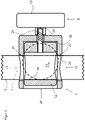
- FIG 1 shows an embodiment of a trampoline according to the invention.
- the trampoline has a frame 1 which is supported by a plurality of legs 2 on the ground.
- the frame holds a jumping sheet 3 which is held on the frame by a large number of spring elements 4 .
- the spring elements 4 can be rubber cable sections that are either open or closed. Both variants are known from the prior art.
- the bungee cord sections can be hooked into receiving elements, for example hook elements, fastened to the jumping mat.
- metal springs are used, which are also known from the prior art.
- a rod 5 is attached to the trampoline.
- the rod 5 is designed as a holding rod and has a handle 6 .
- the rod can also have a holder for an electronic device such as a tablet PC or the like.
- the rod can also take on other tasks.
- a rubber-elastic band can be attached to the bar to support exercises on the trampoline to be attached.
- the support rod 5 is held in a guide 7 which is attached to the frame 1, for example screwed or welded.
- the guide can also be attached to one of the legs 2.
- the support rod 5 is height-adjustable and by means of a (in figure 1 only indicated) actuating device 8 in the guide 7 can be fixed.
- figure 2 shows the guide 7 from figure 1 closer in detail.
- the guide 7 is welded to the frame 1, as can be seen by the weld 9.
- the frame 1 is separated where the guide 7 is inserted and forms a recess A.
- the recess is in figure 6 shown.
- the actuating device 8 has a handle 10 which can be made of plastic.
- the handle sits on an axis of rotation 11, which has a thread, as in connection with Figures 3 and 4 will be described in more detail.
- FIG 3 shows a section through the guide 7 in a schematic representation.
- the guide 7 is welded to the frame 1.
- the frame 1 preferably includes the guide on both sides.
- the frame is in figure 3 indicated with a dashed line.
- the support rod 5 is slidably received in the direction of its longitudinal axis.
- the support bar 5 is in the guide 7 can be fixed.
- an inner piece 12 is movably accommodated in the guide 7 .
- the inner piece 12 is preferably guided in the guide 7 in a displaceable manner.
- the core 12 is substantially cylindrical.
- the guide 7 has two openings 13 which are preferably aligned.
- the inner piece 12 also has an opening 14 .
- the rod 5 can be pushed through the openings 13,14.
- the openings 13, 14 are appropriately aligned and are preferably designed to be larger than the cross section of the rod 5, so that the rod can be inserted through the openings.
- the support rod can have a round cross-section. Alternatively, it has an angular, in particular square, cross section.
- the openings are adapted to the cross-sectional shape of the support rod.
- the inner piece 12 is coupled to the actuating device 8 .
- the inner piece 7 has an internal thread 15 which engages with a threaded pin 16 of the actuating device 8 .
- the threaded stem 16 is rotated by means of the handle 10. Due to the threaded engagement between the inner piece 12 and the actuating device 8, a rotation of the handle 10 leads to a movement of the inner piece 12 in the guide 7.
- the actuating device 8 is supported on the guide 7 here.
- the guide 7 preferably has an end wall 17 on which the actuating device 8 is supported.
- the inner piece 12 is shown in an open position.
- the support rod 15 is movable in the guide. That is, the openings 13 and 14 are aligned so that they leave enough play for the support rod 5 to be moved.
- the cross section of the opening 14 of the inner piece 12 is larger than the cross section of the openings 13 of the guide.
- figure 4 shows the support rod 5 in a fixed state.
- the retaining rod 5 is clamped by turning the handle 10 of the actuator 8 so that the thread 16 pulls the inner piece 12 towards the handle 10, as indicated by the arrow P1.
- the construction can in principle also be such that by actuating the actuating device 8 the inner piece 12 is moved in the other direction, ie counter to the arrow P1, and the holding rod 5 is thus fixed.
- the actuating device 8 must then be supported on the inside 18 of the guide in order to apply the force to the inner piece 12.
- a locking ring can be provided for this purpose, for example.
- the opening 14 also moves in the direction of the arrow P1 until the inside 19 of the inner piece 12 comes to rest against the retaining rod 5.
- the retaining rod 5 is pressed against the inside 20 of the opening 13 of the guide 7 and thereby fixed.
- the holding rod 5 is clamped with a large holding surface provided by the inside 19 .
- the Guide two contact surfaces 21, 22 is available.
- one contact surface 21 is arranged at the top and one contact surface 22 is arranged at the bottom.
- one contact surface 22 can be arranged above the frame and the other contact surface 22 can be arranged below the frame.
- Such an embodiment of the invention creates an advantageous alignment of the support rod 5 with respect to the frame 1.
- figure 5 shows an alternative embodiment to the Figures 3 and 4 .
- the embodiment after figure 5 shows the support rod in a fixed state.
- the embodiment differs from the Figures 3 and 4 in that the actuating device 8 does not have a threaded pin but a nut 23 .
- the inner piece 12 has a threaded pin 24 .
- the inner piece 7 and the actuating device 8 are in threaded engagement.
- the figures 6 and 7 show the interaction of the inner piece 12 and the guide 7.
- the actuating device and the holding rod are omitted from the illustration.
- the inner piece 12 and the guide 7 are in a position in which the openings 13 (of the guide) and 14 (of the inner piece) are aligned. In this position, the support bar can be used.
- the resulting from the superimposition of the openings 13, 14 cut opening must be at least as large as the cross section of Holding rod, so that the holding rod can be pushed through the guide 7 and the inner piece 12.
- figure 7 shows a position of the inner piece 12 in a slightly pulled out of the guide 7 position. It is clear here that it is advantageous if the guide has an opening 25 located radially on the inside. The opening 25 is preferably located opposite the end wall 17 . Through this opening 25, the inner piece 12 can be inserted into the guide 7 for assembly and pulled out for disassembly. So assembly is very easy. At the same time, the combination of the inner piece 12 and the guide 7 creates a stable clamping of the holding rod via the inner sides 19 and 20, as explained above.
- the guide 7 is advantageously designed as a piece of pipe. Such a piece of pipe is easy to produce and stable.
- the pipe piece can have an end wall 17 on one side, through which the actuating device or a threaded pin extending from the inner piece 12 (see figure 5 ) passes through.
- FIG 8 shows an alternative embodiment of the actuating device 8 .
- the actuating device has a clamping lever 26 .
- the clamping lever and the inner piece are preferably in threaded engagement with one another (analogous to the Figures 3 to 5 ). Rough adjustment is possible via the thread.
- the final clamping force is applied via the clamping lever, which is advantageously supported on an intermediate piece 27 or directly on the guide 7. The intermediate piece 27 rests against the guide 7 .
- the frame shape is shown in the figures only around. It can also be polygonal, in particular hexagonal or octagonal.
- indefinite location information such as “above”, “below” or “to the side” is related to a stationary trampoline.
- Location information or direction information such as radially inside or radially outside is also used.
- the frame which can be either round or square (in plan view). If it is round, the round frame forms a center of curvature. The information relates to this point.
- a guide that extends radially lies on a line that extends radially outward from the center of curvature.
- straight frame sections are regularly provided between the corners. The guide will be placed in the middle of the frame sections.
- each frame section intersects at the center of the frame so that, for example, a length of tubing extending radially toward the angular frame lies on a line going radially outward from the center. In the middle of the frame section, this line intersects the frame perpendicularly.
Landscapes
- Engineering & Computer Science (AREA)
- General Engineering & Computer Science (AREA)
- Mechanical Engineering (AREA)
- Health & Medical Sciences (AREA)
- General Health & Medical Sciences (AREA)
- Physical Education & Sports Medicine (AREA)
- Life Sciences & Earth Sciences (AREA)
- Biophysics (AREA)
- Orthopedic Medicine & Surgery (AREA)
- Mutual Connection Of Rods And Tubes (AREA)
- Clamps And Clips (AREA)
- Prostheses (AREA)
Claims (15)
- Trampoline, comportant- un châssis qui comprend un cadre périphérique (1) et une pluralité de pieds (2), le cadre étant constitué d'un tube qui est courbé pour produire le cadre,- une toile de saut (3) qui est suspendue élastiquement au cadre (1),- au moins un guide (7) qui est fixé au châssis,- une tige (5) qui est reçue de manière réglable en hauteur dans le guide (7), et- une pièce intérieure (12) qui est reçue de manière mobile dans le guide (7), caractérisé en ce que la tige (5) est fixée par un mouvement relatif entre la pièce intérieure (12) et le guide (7), et- en ce que le cadre (1) forme un évidement (A) dans lequel le guide (7) est reçu.
- Trampoline selon la revendication 1, caractérisé en ce que le guide (7) comprend au moins une première ouverture (13) à travers laquelle la tige (5) est insérée.
- Trampoline selon la revendication 1 ou 2, caractérisé en ce que le guide (7) comprend une paroi circonférentielle périphérique, et en ce que la première ouverture (13) est réalisée dans la paroi circonférentielle.
- Trampoline selon l'une des revendications 1 à 3, caractérisé en ce que la pièce intérieure (12) comprend une ouverture (14) à travers laquelle la tige (5) s'étend.
- Trampoline selon l'une des revendications 1 à 4, caractérisé en ce que le guide comprend une ouverture (25) à travers laquelle la pièce intérieure (12) peut être insérée dans le guide (7).
- Trampoline selon la revendication 5, caractérisé en ce que l'ouverture (25) est orientée radialement vers l'intérieur.
- Trampoline selon l'une des revendications 1 à 6, caractérisé en ce que la pièce intérieure (12) est accouplée à un dispositif d'actionnement (8) qui est supporté sur le cadre (1) ou de préférence sur le guide (7) ou sur une pièce intermédiaire (26) s'appuyant sur le guide.
- Trampoline selon la revendication 7, caractérisé en ce que le dispositif d'actionnement (8) et la pièce intérieure (12) sont en prise par filetage.
- Trampoline selon la revendication 7 ou 8, caractérisé en ce que le dispositif d'actionnement (8) comprend un goujon fileté (16) qui vient en prise dans un filetage intérieur (15) de la pièce intérieure (12).
- Trampoline selon la revendication 7 ou 8, caractérisé en ce que la pièce intérieure (12) comprend un goujon fileté (16) qui vient en prise dans un filetage intérieur (23) du dispositif d'actionnement (8).
- Trampoline selon l'une des revendications 6 à 9, caractérisé en ce que le dispositif d'actionnement (8) est réalisé sous forme de levier de serrage (25) dont le pivotement provoque un mouvement de la pièce intérieure (12) en direction de levier de serrage.
- Trampoline selon l'une des revendications 1 à 11, caractérisé en ce que le guide (7) est soudé sur le cadre (1).
- Trampoline selon l'une des revendications 1 à 12, caractérisé en ce que le guide (7) est réalisé sous forme de pièce tubulaire.
- Trampoline selon la revendication 13, caractérisé en ce que la pièce tubulaire (7) est disposée perpendiculairement à la direction d'étendue axiale des pieds (2) et s'ouvre de préférence radialement vers l'intérieur.
- Trampoline selon l'une des revendications 1 à 14, caractérisé en ce que le guide (7) comprend une paroi frontale (17).
Applications Claiming Priority (4)
| Application Number | Priority Date | Filing Date | Title |
|---|---|---|---|
| DE102015116819 | 2015-10-04 | ||
| DE102015116820 | 2015-10-04 | ||
| DE102016103072.4A DE102016103072B4 (de) | 2015-10-04 | 2016-02-22 | Trampolin |
| PCT/EP2016/073434 WO2017032907A1 (fr) | 2015-10-04 | 2016-09-30 | Trampoline |
Publications (2)
| Publication Number | Publication Date |
|---|---|
| EP3355998A1 EP3355998A1 (fr) | 2018-08-08 |
| EP3355998B1 true EP3355998B1 (fr) | 2022-04-27 |
Family
ID=57395020
Family Applications (1)
| Application Number | Title | Priority Date | Filing Date |
|---|---|---|---|
| EP16774950.6A Active EP3355998B1 (fr) | 2015-10-04 | 2016-09-30 | Trampolin |
Country Status (5)
| Country | Link |
|---|---|
| US (1) | US10940353B2 (fr) |
| EP (1) | EP3355998B1 (fr) |
| CN (1) | CN108136244A (fr) |
| DE (3) | DE102016103072B4 (fr) |
| SG (1) | SG11201802087YA (fr) |
Families Citing this family (20)
| Publication number | Priority date | Publication date | Assignee | Title |
|---|---|---|---|---|
| USD884103S1 (en) * | 2018-08-13 | 2020-05-12 | Markus Hammer | Trampolines |
| CN108771819B (zh) * | 2018-07-13 | 2020-07-21 | 东莞市建嘉实业有限公司 | 便装式蹦床 |
| FR3088011B1 (fr) * | 2018-11-07 | 2021-12-03 | Yaagoubi Abdelhamid El | Article de sport muni d’un matelas pour la pratique d’exercice physique, ayant un element de guidage d’un accessoire de prehension. |
| IT201800010092A1 (it) * | 2018-11-08 | 2019-02-08 | Davide Marchesi | Sistema di bloccaggio manuale per gambe telescopiche |
| DE102019109961A1 (de) * | 2019-04-15 | 2020-10-15 | Bellicon Ag | Stangenhalterung |
| CN110353926A (zh) * | 2019-07-08 | 2019-10-22 | 徐州雅来基桑拿设备有限公司 | 一种可折叠桑拿浴床 |
| USD966440S1 (en) | 2019-10-28 | 2022-10-11 | Pure Global Brands, Inc. | Mini trampoline |
| USD966438S1 (en) | 2019-10-28 | 2022-10-11 | Pure Global Brands, Inc. | Mini trampoline |
| USD966439S1 (en) | 2019-10-28 | 2022-10-11 | Pure Global Brands, Inc. | Mini trampoline |
| CN110947151A (zh) * | 2019-12-20 | 2020-04-03 | 东莞市建嘉实业有限公司 | 一种稳固盆形蹦床 |
| US11504563B2 (en) | 2020-02-06 | 2022-11-22 | Pure Global Brands, Inc. | Mini-trampoline |
| USD966451S1 (en) | 2020-06-10 | 2022-10-11 | Pure Global Brands, Inc. | Trampoline |
| USD966450S1 (en) * | 2020-06-10 | 2022-10-11 | Pure Global Brands, Inc. | Trampoline |
| USD933154S1 (en) * | 2020-07-28 | 2021-10-12 | Haiqiong Chen | Trampoline |
| USD920458S1 (en) * | 2020-09-30 | 2021-05-25 | Guangzhou YuanPiao YunDong YongPin YouXian GongSi | Trampoline |
| USD941414S1 (en) * | 2021-01-13 | 2022-01-18 | Guangzhou YuanPiao YunDong YongPin YouXian GongSi | Trampoline |
| USD993293S1 (en) | 2021-04-27 | 2023-07-25 | Bellicon Ag | Holding device with sleeve |
| DE102022105672A1 (de) | 2022-03-10 | 2023-09-14 | KROMA INTERNATIONAL GmbH | Vorrichtung zum Verbinden einer Haltestange mit einem Ring eines Trampolins |
| US11724145B1 (en) * | 2022-05-16 | 2023-08-15 | Milton Stamper | Combination trampoline and pole device, a retrofit trampoline and pole device for use with a water structure, and an entertainment system |
| DE102022117523A1 (de) | 2022-07-13 | 2024-01-18 | Bellicon Ag | Stangenhalterung für Trampoline |
Citations (4)
| Publication number | Priority date | Publication date | Assignee | Title |
|---|---|---|---|---|
| US6261207B1 (en) * | 1997-06-20 | 2001-07-17 | Jumpsport, Inc. | Trampoline or the like with enclosure |
| US20070012902A1 (en) * | 2005-07-14 | 2007-01-18 | Zhiping Mo | Safety Fence and Protection Pole Connection Apparatus for Trampoline |
| US8657129B2 (en) * | 2010-12-07 | 2014-02-25 | Avedis Zildjian Co. | Drum rack |
| DE202014007636U1 (de) * | 2014-09-18 | 2014-10-24 | Ds Produkte Gmbh | Trampolin mit demontierbarem Haltegriff |
Family Cites Families (18)
| Publication number | Priority date | Publication date | Assignee | Title |
|---|---|---|---|---|
| US2854293A (en) | 1953-10-26 | 1958-09-30 | Henry J Riblet | Combined scaffold bracket and lock |
| US3195938A (en) | 1962-04-09 | 1965-07-20 | Louis L Rifken | Coupling means for building frameworks, racks, scaffolds, and the like |
| US4657218A (en) * | 1986-01-21 | 1987-04-14 | J. I. Case Company | Adjustable chair pedestal |
| US4836530A (en) * | 1988-05-16 | 1989-06-06 | Stanley Jr Bedford F | Trampoline-like aerobic exercise apparatus and method |
| US5374225A (en) * | 1992-09-16 | 1994-12-20 | Wilkinson; William T. | Resilient platform exercise device |
| US5607377A (en) * | 1994-05-09 | 1997-03-04 | Wilkinson; William T. | Rebounder and punching bag-boxing fitness device |
| DE69428902T2 (de) | 1994-12-16 | 2002-06-27 | William T Wilkinson | Elastische Übungsbühne |
| CN2421045Y (zh) | 2000-04-18 | 2001-02-28 | 陈清泉 | 改进的把手杆固定装置 |
| US8652011B2 (en) | 2006-07-10 | 2014-02-18 | Ca06, Llc | Frame structure for a safety enclosure for a recreational structure |
| CN2934696Y (zh) | 2006-07-26 | 2007-08-15 | 杭州泛亚休闲用品有限公司 | 安全管连接结构 |
| WO2008029166A1 (fr) | 2006-09-08 | 2008-03-13 | Plum Products Ltd | Élément d'accouplement |
| CN201099330Y (zh) | 2007-07-11 | 2008-08-13 | 深圳信隆实业股份有限公司 | 快拆装置及其扳柄 |
| US20100240496A1 (en) * | 2009-03-18 | 2010-09-23 | Samuel Chen | Trampoline frame |
| DE202011106375U1 (de) | 2011-09-27 | 2012-05-02 | Monz Gmbh & Co. Kg | Rahmenkonstruktion eines Trampolins |
| US20140241789A1 (en) * | 2013-02-28 | 2014-08-28 | E Dan Industrial Co., Ltd | Locking device for an extendible tube assembly |
| CN103639785A (zh) | 2013-12-06 | 2014-03-19 | 蔡利锋 | 简易式快速压板 |
| CN204344594U (zh) | 2014-11-04 | 2015-05-20 | 王声贤 | 一种螺丝组件 |
| CN204543368U (zh) | 2015-03-06 | 2015-08-12 | 曾广安 | 蹦床及其安装工具 |
-
2016
- 2016-02-22 DE DE102016103072.4A patent/DE102016103072B4/de active Active
- 2016-02-22 DE DE202016100930.8U patent/DE202016100930U1/de active Active
- 2016-02-22 DE DE202016100929.4U patent/DE202016100929U1/de active Active
- 2016-09-30 SG SG11201802087YA patent/SG11201802087YA/en unknown
- 2016-09-30 US US15/765,870 patent/US10940353B2/en active Active
- 2016-09-30 EP EP16774950.6A patent/EP3355998B1/fr active Active
- 2016-09-30 CN CN201680058058.9A patent/CN108136244A/zh active Pending
Patent Citations (4)
| Publication number | Priority date | Publication date | Assignee | Title |
|---|---|---|---|---|
| US6261207B1 (en) * | 1997-06-20 | 2001-07-17 | Jumpsport, Inc. | Trampoline or the like with enclosure |
| US20070012902A1 (en) * | 2005-07-14 | 2007-01-18 | Zhiping Mo | Safety Fence and Protection Pole Connection Apparatus for Trampoline |
| US8657129B2 (en) * | 2010-12-07 | 2014-02-25 | Avedis Zildjian Co. | Drum rack |
| DE202014007636U1 (de) * | 2014-09-18 | 2014-10-24 | Ds Produkte Gmbh | Trampolin mit demontierbarem Haltegriff |
Also Published As
| Publication number | Publication date |
|---|---|
| DE202016100930U1 (de) | 2016-11-07 |
| US10940353B2 (en) | 2021-03-09 |
| EP3355998A1 (fr) | 2018-08-08 |
| US20180280750A1 (en) | 2018-10-04 |
| SG11201802087YA (en) | 2018-04-27 |
| CN108136244A (zh) | 2018-06-08 |
| DE202016100929U1 (de) | 2016-11-07 |
| DE102016103072A1 (de) | 2017-04-06 |
| DE102016103072B4 (de) | 2018-05-30 |
Similar Documents
| Publication | Publication Date | Title |
|---|---|---|
| EP3355998B1 (fr) | Trampolin | |
| EP0868128B1 (fr) | Poignee de baton | |
| WO2006108715A1 (fr) | Dispositif tendeur de corde pour reseaux de cordes | |
| EP3725379B1 (fr) | Fixation de tige | |
| WO2016041532A1 (fr) | Trampoline avec poignée de maintien démontable | |
| DE69922608T2 (de) | Stütze | |
| WO2011083093A1 (fr) | Trampoline | |
| DE202012103405U1 (de) | Anschlagpunkt | |
| WO2017032907A1 (fr) | Trampoline | |
| DE202015105222U1 (de) | Trampolin | |
| DE202008006772U1 (de) | Faltbarer Gehstock mit Stoßdämpfungsstruktur | |
| WO2005087581A2 (fr) | Ensemble etrier | |
| DE102020127318A1 (de) | Neuartiges Fitnessgerät und zugehörige Gewichtsverstellungsvorrichtung | |
| DE19857456C2 (de) | Gehhilfe | |
| EP3838669A1 (fr) | Barre de verrouillage à installer dans un espace de chargement d'un véhicule | |
| WO2024012880A1 (fr) | Support de tige pour trampolines | |
| DE202015105221U1 (de) | Trampolin | |
| DE202016105360U1 (de) | Trampolin | |
| DE4027720C2 (de) | Gestell bzw. Beinanordnung, insbesondere eines Möbels, mit wenigstens einem teleskopartig verlängerbaren Standbein und Verfahren zu seiner Herstellung | |
| DE20317442U1 (de) | Teleskopierbares Bauelement für Möbel | |
| DE202011002571U1 (de) | Schrägstütze | |
| DE202006012785U1 (de) | Bodenanker | |
| DE19625175C2 (de) | Hubgestell für eine an einem Sitz angeordnete Kopfstütze | |
| DE102005012428B4 (de) | Vorrichtung zur Positionsverstellung eines Möbels | |
| DE8318655U1 (de) | Springstab |
Legal Events
| Date | Code | Title | Description |
|---|---|---|---|
| STAA | Information on the status of an ep patent application or granted ep patent |
Free format text: STATUS: THE INTERNATIONAL PUBLICATION HAS BEEN MADE |
|
| PUAI | Public reference made under article 153(3) epc to a published international application that has entered the european phase |
Free format text: ORIGINAL CODE: 0009012 |
|
| STAA | Information on the status of an ep patent application or granted ep patent |
Free format text: STATUS: REQUEST FOR EXAMINATION WAS MADE |
|
| 17P | Request for examination filed |
Effective date: 20180413 |
|
| AK | Designated contracting states |
Kind code of ref document: A1 Designated state(s): AL AT BE BG CH CY CZ DE DK EE ES FI FR GB GR HR HU IE IS IT LI LT LU LV MC MK MT NL NO PL PT RO RS SE SI SK SM TR |
|
| AX | Request for extension of the european patent |
Extension state: BA ME |
|
| DAV | Request for validation of the european patent (deleted) | ||
| DAX | Request for extension of the european patent (deleted) | ||
| STAA | Information on the status of an ep patent application or granted ep patent |
Free format text: STATUS: EXAMINATION IS IN PROGRESS |
|
| 17Q | First examination report despatched |
Effective date: 20191213 |
|
| STAA | Information on the status of an ep patent application or granted ep patent |
Free format text: STATUS: EXAMINATION IS IN PROGRESS |
|
| RAP3 | Party data changed (applicant data changed or rights of an application transferred) |
Owner name: BELLICON AG |
|
| REG | Reference to a national code |
Ref country code: DE Ref legal event code: R079 Ref document number: 502016014822 Country of ref document: DE Free format text: PREVIOUS MAIN CLASS: A63B0005110000 Ipc: A63B0021020000 |
|
| RIC1 | Information provided on ipc code assigned before grant |
Ipc: A63B 5/11 20060101ALI20211103BHEP Ipc: F16B 7/04 20060101ALI20211103BHEP Ipc: F16B 7/14 20060101ALI20211103BHEP Ipc: F16B 2/18 20060101ALI20211103BHEP Ipc: F16B 2/12 20060101ALI20211103BHEP Ipc: F16B 2/06 20060101ALI20211103BHEP Ipc: A63B 21/055 20060101ALI20211103BHEP Ipc: A63B 21/02 20060101AFI20211103BHEP |
|
| GRAP | Despatch of communication of intention to grant a patent |
Free format text: ORIGINAL CODE: EPIDOSNIGR1 |
|
| STAA | Information on the status of an ep patent application or granted ep patent |
Free format text: STATUS: GRANT OF PATENT IS INTENDED |
|
| INTG | Intention to grant announced |
Effective date: 20211213 |
|
| GRAS | Grant fee paid |
Free format text: ORIGINAL CODE: EPIDOSNIGR3 |
|
| GRAA | (expected) grant |
Free format text: ORIGINAL CODE: 0009210 |
|
| STAA | Information on the status of an ep patent application or granted ep patent |
Free format text: STATUS: THE PATENT HAS BEEN GRANTED |
|
| AK | Designated contracting states |
Kind code of ref document: B1 Designated state(s): AL AT BE BG CH CY CZ DE DK EE ES FI FR GB GR HR HU IE IS IT LI LT LU LV MC MK MT NL NO PL PT RO RS SE SI SK SM TR |
|
| REG | Reference to a national code |
Ref country code: GB Ref legal event code: FG4D Free format text: NOT ENGLISH |
|
| REG | Reference to a national code |
Ref country code: CH Ref legal event code: EP |
|
| REG | Reference to a national code |
Ref country code: DE Ref legal event code: R096 Ref document number: 502016014822 Country of ref document: DE |
|
| REG | Reference to a national code |
Ref country code: AT Ref legal event code: REF Ref document number: 1486464 Country of ref document: AT Kind code of ref document: T Effective date: 20220515 |
|
| REG | Reference to a national code |
Ref country code: IE Ref legal event code: FG4D Free format text: LANGUAGE OF EP DOCUMENT: GERMAN |
|
| REG | Reference to a national code |
Ref country code: LT Ref legal event code: MG9D |
|
| REG | Reference to a national code |
Ref country code: NL Ref legal event code: MP Effective date: 20220427 |
|
| PG25 | Lapsed in a contracting state [announced via postgrant information from national office to epo] |
Ref country code: NL Free format text: LAPSE BECAUSE OF FAILURE TO SUBMIT A TRANSLATION OF THE DESCRIPTION OR TO PAY THE FEE WITHIN THE PRESCRIBED TIME-LIMIT Effective date: 20220427 |
|
| PG25 | Lapsed in a contracting state [announced via postgrant information from national office to epo] |
Ref country code: SE Free format text: LAPSE BECAUSE OF FAILURE TO SUBMIT A TRANSLATION OF THE DESCRIPTION OR TO PAY THE FEE WITHIN THE PRESCRIBED TIME-LIMIT Effective date: 20220427 Ref country code: PT Free format text: LAPSE BECAUSE OF FAILURE TO SUBMIT A TRANSLATION OF THE DESCRIPTION OR TO PAY THE FEE WITHIN THE PRESCRIBED TIME-LIMIT Effective date: 20220829 Ref country code: NO Free format text: LAPSE BECAUSE OF FAILURE TO SUBMIT A TRANSLATION OF THE DESCRIPTION OR TO PAY THE FEE WITHIN THE PRESCRIBED TIME-LIMIT Effective date: 20220727 Ref country code: LT Free format text: LAPSE BECAUSE OF FAILURE TO SUBMIT A TRANSLATION OF THE DESCRIPTION OR TO PAY THE FEE WITHIN THE PRESCRIBED TIME-LIMIT Effective date: 20220427 Ref country code: HR Free format text: LAPSE BECAUSE OF FAILURE TO SUBMIT A TRANSLATION OF THE DESCRIPTION OR TO PAY THE FEE WITHIN THE PRESCRIBED TIME-LIMIT Effective date: 20220427 Ref country code: GR Free format text: LAPSE BECAUSE OF FAILURE TO SUBMIT A TRANSLATION OF THE DESCRIPTION OR TO PAY THE FEE WITHIN THE PRESCRIBED TIME-LIMIT Effective date: 20220728 Ref country code: FI Free format text: LAPSE BECAUSE OF FAILURE TO SUBMIT A TRANSLATION OF THE DESCRIPTION OR TO PAY THE FEE WITHIN THE PRESCRIBED TIME-LIMIT Effective date: 20220427 Ref country code: ES Free format text: LAPSE BECAUSE OF FAILURE TO SUBMIT A TRANSLATION OF THE DESCRIPTION OR TO PAY THE FEE WITHIN THE PRESCRIBED TIME-LIMIT Effective date: 20220427 Ref country code: BG Free format text: LAPSE BECAUSE OF FAILURE TO SUBMIT A TRANSLATION OF THE DESCRIPTION OR TO PAY THE FEE WITHIN THE PRESCRIBED TIME-LIMIT Effective date: 20220727 |
|
| PG25 | Lapsed in a contracting state [announced via postgrant information from national office to epo] |
Ref country code: RS Free format text: LAPSE BECAUSE OF FAILURE TO SUBMIT A TRANSLATION OF THE DESCRIPTION OR TO PAY THE FEE WITHIN THE PRESCRIBED TIME-LIMIT Effective date: 20220427 Ref country code: PL Free format text: LAPSE BECAUSE OF FAILURE TO SUBMIT A TRANSLATION OF THE DESCRIPTION OR TO PAY THE FEE WITHIN THE PRESCRIBED TIME-LIMIT Effective date: 20220427 Ref country code: LV Free format text: LAPSE BECAUSE OF FAILURE TO SUBMIT A TRANSLATION OF THE DESCRIPTION OR TO PAY THE FEE WITHIN THE PRESCRIBED TIME-LIMIT Effective date: 20220427 Ref country code: IS Free format text: LAPSE BECAUSE OF FAILURE TO SUBMIT A TRANSLATION OF THE DESCRIPTION OR TO PAY THE FEE WITHIN THE PRESCRIBED TIME-LIMIT Effective date: 20220827 |
|
| REG | Reference to a national code |
Ref country code: DE Ref legal event code: R097 Ref document number: 502016014822 Country of ref document: DE |
|
| PG25 | Lapsed in a contracting state [announced via postgrant information from national office to epo] |
Ref country code: SM Free format text: LAPSE BECAUSE OF FAILURE TO SUBMIT A TRANSLATION OF THE DESCRIPTION OR TO PAY THE FEE WITHIN THE PRESCRIBED TIME-LIMIT Effective date: 20220427 Ref country code: SK Free format text: LAPSE BECAUSE OF FAILURE TO SUBMIT A TRANSLATION OF THE DESCRIPTION OR TO PAY THE FEE WITHIN THE PRESCRIBED TIME-LIMIT Effective date: 20220427 Ref country code: RO Free format text: LAPSE BECAUSE OF FAILURE TO SUBMIT A TRANSLATION OF THE DESCRIPTION OR TO PAY THE FEE WITHIN THE PRESCRIBED TIME-LIMIT Effective date: 20220427 Ref country code: EE Free format text: LAPSE BECAUSE OF FAILURE TO SUBMIT A TRANSLATION OF THE DESCRIPTION OR TO PAY THE FEE WITHIN THE PRESCRIBED TIME-LIMIT Effective date: 20220427 Ref country code: DK Free format text: LAPSE BECAUSE OF FAILURE TO SUBMIT A TRANSLATION OF THE DESCRIPTION OR TO PAY THE FEE WITHIN THE PRESCRIBED TIME-LIMIT Effective date: 20220427 Ref country code: CZ Free format text: LAPSE BECAUSE OF FAILURE TO SUBMIT A TRANSLATION OF THE DESCRIPTION OR TO PAY THE FEE WITHIN THE PRESCRIBED TIME-LIMIT Effective date: 20220427 |
|
| PLBE | No opposition filed within time limit |
Free format text: ORIGINAL CODE: 0009261 |
|
| STAA | Information on the status of an ep patent application or granted ep patent |
Free format text: STATUS: NO OPPOSITION FILED WITHIN TIME LIMIT |
|
| PG25 | Lapsed in a contracting state [announced via postgrant information from national office to epo] |
Ref country code: AL Free format text: LAPSE BECAUSE OF FAILURE TO SUBMIT A TRANSLATION OF THE DESCRIPTION OR TO PAY THE FEE WITHIN THE PRESCRIBED TIME-LIMIT Effective date: 20220427 |
|
| 26N | No opposition filed |
Effective date: 20230130 |
|
| PG25 | Lapsed in a contracting state [announced via postgrant information from national office to epo] |
Ref country code: MC Free format text: LAPSE BECAUSE OF FAILURE TO SUBMIT A TRANSLATION OF THE DESCRIPTION OR TO PAY THE FEE WITHIN THE PRESCRIBED TIME-LIMIT Effective date: 20220427 |
|
| REG | Reference to a national code |
Ref country code: BE Ref legal event code: MM Effective date: 20220930 |
|
| PG25 | Lapsed in a contracting state [announced via postgrant information from national office to epo] |
Ref country code: SI Free format text: LAPSE BECAUSE OF FAILURE TO SUBMIT A TRANSLATION OF THE DESCRIPTION OR TO PAY THE FEE WITHIN THE PRESCRIBED TIME-LIMIT Effective date: 20220427 |
|
| PG25 | Lapsed in a contracting state [announced via postgrant information from national office to epo] |
Ref country code: LU Free format text: LAPSE BECAUSE OF NON-PAYMENT OF DUE FEES Effective date: 20220930 |
|
| P01 | Opt-out of the competence of the unified patent court (upc) registered |
Effective date: 20230601 |
|
| PG25 | Lapsed in a contracting state [announced via postgrant information from national office to epo] |
Ref country code: IE Free format text: LAPSE BECAUSE OF NON-PAYMENT OF DUE FEES Effective date: 20220930 Ref country code: FR Free format text: LAPSE BECAUSE OF NON-PAYMENT OF DUE FEES Effective date: 20220930 |
|
| PG25 | Lapsed in a contracting state [announced via postgrant information from national office to epo] |
Ref country code: BE Free format text: LAPSE BECAUSE OF NON-PAYMENT OF DUE FEES Effective date: 20220930 |
|
| PGFP | Annual fee paid to national office [announced via postgrant information from national office to epo] |
Ref country code: GB Payment date: 20230920 Year of fee payment: 8 |
|
| REG | Reference to a national code |
Ref country code: AT Ref legal event code: MM01 Ref document number: 1486464 Country of ref document: AT Kind code of ref document: T Effective date: 20220930 |
|
| PGFP | Annual fee paid to national office [announced via postgrant information from national office to epo] |
Ref country code: DE Payment date: 20230930 Year of fee payment: 8 |
|
| PG25 | Lapsed in a contracting state [announced via postgrant information from national office to epo] |
Ref country code: IT Free format text: LAPSE BECAUSE OF FAILURE TO SUBMIT A TRANSLATION OF THE DESCRIPTION OR TO PAY THE FEE WITHIN THE PRESCRIBED TIME-LIMIT Effective date: 20220427 Ref country code: AT Free format text: LAPSE BECAUSE OF NON-PAYMENT OF DUE FEES Effective date: 20220930 |
|
| PGFP | Annual fee paid to national office [announced via postgrant information from national office to epo] |
Ref country code: CH Payment date: 20231001 Year of fee payment: 8 |
|
| PG25 | Lapsed in a contracting state [announced via postgrant information from national office to epo] |
Ref country code: HU Free format text: LAPSE BECAUSE OF FAILURE TO SUBMIT A TRANSLATION OF THE DESCRIPTION OR TO PAY THE FEE WITHIN THE PRESCRIBED TIME-LIMIT; INVALID AB INITIO Effective date: 20160930 |
|
| PG25 | Lapsed in a contracting state [announced via postgrant information from national office to epo] |
Ref country code: CY Free format text: LAPSE BECAUSE OF FAILURE TO SUBMIT A TRANSLATION OF THE DESCRIPTION OR TO PAY THE FEE WITHIN THE PRESCRIBED TIME-LIMIT Effective date: 20220427 |