EP3355376B1 - Organic electroluminescent element - Google Patents
Organic electroluminescent element Download PDFInfo
- Publication number
- EP3355376B1 EP3355376B1 EP16848553.0A EP16848553A EP3355376B1 EP 3355376 B1 EP3355376 B1 EP 3355376B1 EP 16848553 A EP16848553 A EP 16848553A EP 3355376 B1 EP3355376 B1 EP 3355376B1
- Authority
- EP
- European Patent Office
- Prior art keywords
- group
- carbon atoms
- transport layer
- triarylamine
- compound
- Prior art date
- Legal status (The legal status is an assumption and is not a legal conclusion. Google has not performed a legal analysis and makes no representation as to the accuracy of the status listed.)
- Active
Links
- -1 arylamine compound Chemical class 0.000 claims description 159
- 239000000463 material Substances 0.000 claims description 110
- 230000005525 hole transport Effects 0.000 claims description 89
- 125000005259 triarylamine group Chemical group 0.000 claims description 85
- 125000004432 carbon atom Chemical group C* 0.000 claims description 81
- 125000006615 aromatic heterocyclic group Chemical group 0.000 claims description 56
- 150000003230 pyrimidines Chemical class 0.000 claims description 52
- 125000002029 aromatic hydrocarbon group Chemical group 0.000 claims description 44
- 125000003342 alkenyl group Chemical group 0.000 claims description 24
- 125000000217 alkyl group Chemical group 0.000 claims description 22
- 229910052805 deuterium Inorganic materials 0.000 claims description 22
- 229910052717 sulfur Inorganic materials 0.000 claims description 21
- 125000004435 hydrogen atom Chemical group [H]* 0.000 claims description 20
- 125000003545 alkoxy group Chemical group 0.000 claims description 17
- 125000004104 aryloxy group Chemical group 0.000 claims description 15
- 125000004430 oxygen atom Chemical group O* 0.000 claims description 15
- 125000004434 sulfur atom Chemical group 0.000 claims description 15
- 125000003118 aryl group Chemical group 0.000 claims description 14
- 125000000753 cycloalkyl group Chemical group 0.000 claims description 13
- 229910052801 chlorine Inorganic materials 0.000 claims description 10
- 125000001309 chloro group Chemical group Cl* 0.000 claims description 10
- 125000001570 methylene group Chemical group [H]C([H])([*:1])[*:2] 0.000 claims description 10
- 125000004093 cyano group Chemical group *C#N 0.000 claims description 9
- 125000000000 cycloalkoxy group Chemical group 0.000 claims description 9
- 229910052731 fluorine Inorganic materials 0.000 claims description 9
- 125000001153 fluoro group Chemical group F* 0.000 claims description 9
- 125000000449 nitro group Chemical group [O-][N+](*)=O 0.000 claims description 9
- 150000001454 anthracenes Chemical class 0.000 claims description 8
- 150000004945 aromatic hydrocarbons Chemical class 0.000 claims description 7
- 239000002019 doping agent Substances 0.000 claims description 7
- 125000005581 pyrene group Chemical group 0.000 claims description 2
- 125000004431 deuterium atom Chemical group 0.000 claims 2
- 239000010410 layer Substances 0.000 description 221
- 150000001875 compounds Chemical class 0.000 description 109
- 125000001424 substituent group Chemical group 0.000 description 84
- 230000015572 biosynthetic process Effects 0.000 description 69
- 238000003786 synthesis reaction Methods 0.000 description 50
- 238000002347 injection Methods 0.000 description 44
- 239000007924 injection Substances 0.000 description 44
- OKKJLVBELUTLKV-UHFFFAOYSA-N Methanol Chemical compound OC OKKJLVBELUTLKV-UHFFFAOYSA-N 0.000 description 42
- 125000001997 phenyl group Chemical group [H]C1=C([H])C([H])=C(*)C([H])=C1[H] 0.000 description 41
- 239000010408 film Substances 0.000 description 28
- YXFVVABEGXRONW-UHFFFAOYSA-N Toluene Chemical compound CC1=CC=CC=C1 YXFVVABEGXRONW-UHFFFAOYSA-N 0.000 description 27
- 230000000903 blocking effect Effects 0.000 description 27
- 239000000203 mixture Substances 0.000 description 24
- 125000001624 naphthyl group Chemical group 0.000 description 19
- 239000000843 powder Substances 0.000 description 19
- 229940083082 pyrimidine derivative acting on arteriolar smooth muscle Drugs 0.000 description 19
- 239000010409 thin film Substances 0.000 description 19
- 150000001975 deuterium Chemical group 0.000 description 18
- HEDRZPFGACZZDS-MICDWDOJSA-N Trichloro(2H)methane Chemical compound [2H]C(Cl)(Cl)Cl HEDRZPFGACZZDS-MICDWDOJSA-N 0.000 description 16
- 125000004988 dibenzothienyl group Chemical group C1(=CC=CC=2SC3=C(C21)C=CC=C3)* 0.000 description 15
- 125000001792 phenanthrenyl group Chemical group C1(=CC=CC=2C3=CC=CC=C3C=CC12)* 0.000 description 14
- 239000000758 substrate Substances 0.000 description 14
- 125000003914 fluoranthenyl group Chemical group C1(=CC=C2C=CC=C3C4=CC=CC=C4C1=C23)* 0.000 description 13
- 125000003983 fluorenyl group Chemical group C1(=CC=CC=2C3=CC=CC=C3CC12)* 0.000 description 13
- 125000003960 triphenylenyl group Chemical group C1(=CC=CC=2C3=CC=CC=C3C3=CC=CC=C3C12)* 0.000 description 13
- YJTKZCDBKVTVBY-UHFFFAOYSA-N 1,3-Diphenylbenzene Chemical group C1=CC=CC=C1C1=CC=CC(C=2C=CC=CC=2)=C1 YJTKZCDBKVTVBY-UHFFFAOYSA-N 0.000 description 12
- UHOVQNZJYSORNB-UHFFFAOYSA-N Benzene Chemical compound C1=CC=CC=C1 UHOVQNZJYSORNB-UHFFFAOYSA-N 0.000 description 12
- 125000000499 benzofuranyl group Chemical group O1C(=CC2=C1C=CC=C2)* 0.000 description 12
- 125000004196 benzothienyl group Chemical group S1C(=CC2=C1C=CC=C2)* 0.000 description 12
- 239000012295 chemical reaction liquid Substances 0.000 description 12
- 230000000052 comparative effect Effects 0.000 description 12
- 125000002541 furyl group Chemical group 0.000 description 12
- 125000001725 pyrenyl group Chemical group 0.000 description 12
- 125000001544 thienyl group Chemical group 0.000 description 12
- 125000000843 phenylene group Chemical group C1(=C(C=CC=C1)*)* 0.000 description 11
- 238000005481 NMR spectroscopy Methods 0.000 description 10
- 125000002178 anthracenyl group Chemical group C1(=CC=CC2=CC3=CC=CC=C3C=C12)* 0.000 description 10
- 239000012043 crude product Substances 0.000 description 10
- 230000009477 glass transition Effects 0.000 description 10
- BWHMMNNQKKPAPP-UHFFFAOYSA-L potassium carbonate Chemical compound [K+].[K+].[O-]C([O-])=O BWHMMNNQKKPAPP-UHFFFAOYSA-L 0.000 description 10
- 238000005160 1H NMR spectroscopy Methods 0.000 description 9
- FKLJPTJMIBLJAV-UHFFFAOYSA-N Compound IV Chemical compound O1N=C(C)C=C1CCCCCCCOC1=CC=C(C=2OCCN=2)C=C1 FKLJPTJMIBLJAV-UHFFFAOYSA-N 0.000 description 9
- XEKOWRVHYACXOJ-UHFFFAOYSA-N Ethyl acetate Chemical compound CCOC(C)=O XEKOWRVHYACXOJ-UHFFFAOYSA-N 0.000 description 9
- 238000006243 chemical reaction Methods 0.000 description 9
- NLFBCYMMUAKCPC-KQQUZDAGSA-N ethyl (e)-3-[3-amino-2-cyano-1-[(e)-3-ethoxy-3-oxoprop-1-enyl]sulfanyl-3-oxoprop-1-enyl]sulfanylprop-2-enoate Chemical compound CCOC(=O)\C=C\SC(=C(C#N)C(N)=O)S\C=C\C(=O)OCC NLFBCYMMUAKCPC-KQQUZDAGSA-N 0.000 description 9
- 125000001041 indolyl group Chemical group 0.000 description 9
- 125000002080 perylenyl group Chemical group C1(=CC=C2C=CC=C3C4=CC=CC5=CC=CC(C1=C23)=C45)* 0.000 description 9
- 238000000746 purification Methods 0.000 description 9
- 125000001567 quinoxalinyl group Chemical group N1=C(C=NC2=CC=CC=C12)* 0.000 description 9
- 125000000391 vinyl group Chemical group [H]C([*])=C([H])[H] 0.000 description 9
- UFWIBTONFRDIAS-UHFFFAOYSA-N Naphthalene Chemical compound C1=CC=CC2=CC=CC=C21 UFWIBTONFRDIAS-UHFFFAOYSA-N 0.000 description 8
- QVGXLLKOCUKJST-UHFFFAOYSA-N atomic oxygen Chemical compound [O] QVGXLLKOCUKJST-UHFFFAOYSA-N 0.000 description 8
- 125000003785 benzimidazolyl group Chemical group N1=C(NC2=C1C=CC=C2)* 0.000 description 8
- 125000000609 carbazolyl group Chemical group C1(=CC=CC=2C3=CC=CC=C3NC12)* 0.000 description 8
- 238000001914 filtration Methods 0.000 description 8
- 125000003454 indenyl group Chemical group C1(C=CC2=CC=CC=C12)* 0.000 description 8
- 125000005956 isoquinolyl group Chemical group 0.000 description 8
- 238000000034 method Methods 0.000 description 8
- 229910052760 oxygen Inorganic materials 0.000 description 8
- 239000001301 oxygen Substances 0.000 description 8
- 125000004076 pyridyl group Chemical group 0.000 description 8
- 125000005493 quinolyl group Chemical group 0.000 description 8
- 239000007787 solid Substances 0.000 description 8
- 239000000126 substance Substances 0.000 description 8
- 125000001164 benzothiazolyl group Chemical group S1C(=NC2=C1C=CC=C2)* 0.000 description 7
- 125000004541 benzoxazolyl group Chemical group O1C(=NC2=C1C=CC=C2)* 0.000 description 7
- 238000002425 crystallisation Methods 0.000 description 7
- 230000008025 crystallization Effects 0.000 description 7
- 125000000168 pyrrolyl group Chemical group 0.000 description 7
- 239000000243 solution Substances 0.000 description 7
- RFFLAFLAYFXFSW-UHFFFAOYSA-N 1,2-dichlorobenzene Chemical compound ClC1=CC=CC=C1Cl RFFLAFLAYFXFSW-UHFFFAOYSA-N 0.000 description 6
- LFQSCWFLJHTTHZ-UHFFFAOYSA-N Ethanol Chemical compound CCO LFQSCWFLJHTTHZ-UHFFFAOYSA-N 0.000 description 6
- NINIDFKCEFEMDL-UHFFFAOYSA-N Sulfur Chemical compound [S] NINIDFKCEFEMDL-UHFFFAOYSA-N 0.000 description 6
- 150000004982 aromatic amines Chemical class 0.000 description 6
- 125000004623 carbolinyl group Chemical group 0.000 description 6
- MVPPADPHJFYWMZ-UHFFFAOYSA-N chlorobenzene Chemical compound ClC1=CC=CC=C1 MVPPADPHJFYWMZ-UHFFFAOYSA-N 0.000 description 6
- 239000011521 glass Substances 0.000 description 6
- 125000003226 pyrazolyl group Chemical group 0.000 description 6
- 125000000714 pyrimidinyl group Chemical group 0.000 description 6
- 239000011593 sulfur Substances 0.000 description 6
- 0 CCCC(CN)C(NCC***)=C(*C)*=** Chemical compound CCCC(CN)C(NCC***)=C(*C)*=** 0.000 description 5
- VYPSYNLAJGMNEJ-UHFFFAOYSA-N Silicium dioxide Chemical compound O=[Si]=O VYPSYNLAJGMNEJ-UHFFFAOYSA-N 0.000 description 5
- 125000004062 acenaphthenyl group Chemical group C1(CC2=CC=CC3=CC=CC1=C23)* 0.000 description 5
- 229910052751 metal Inorganic materials 0.000 description 5
- 239000002184 metal Substances 0.000 description 5
- 239000012044 organic layer Substances 0.000 description 5
- 229910000027 potassium carbonate Inorganic materials 0.000 description 5
- 239000000741 silica gel Substances 0.000 description 5
- 229910002027 silica gel Inorganic materials 0.000 description 5
- 238000007740 vapor deposition Methods 0.000 description 5
- 125000003903 2-propenyl group Chemical group [H]C([*])([H])C([H])=C([H])[H] 0.000 description 4
- LIDBMZYKSAXTQG-UHFFFAOYSA-N 3-[4-(aminomethyl)-6-(trifluoromethyl)pyridin-2-yl]oxy-N-(2-sulfamoylethyl)benzamide Chemical compound NCC1=CC(=NC(=C1)C(F)(F)F)OC=1C=C(C(=O)NCCS(N)(=O)=O)C=CC=1 LIDBMZYKSAXTQG-UHFFFAOYSA-N 0.000 description 4
- CSCPPACGZOOCGX-UHFFFAOYSA-N Acetone Chemical compound CC(C)=O CSCPPACGZOOCGX-UHFFFAOYSA-N 0.000 description 4
- IMNFDUFMRHMDMM-UHFFFAOYSA-N N-Heptane Chemical compound CCCCCCC IMNFDUFMRHMDMM-UHFFFAOYSA-N 0.000 description 4
- WYURNTSHIVDZCO-UHFFFAOYSA-N Tetrahydrofuran Chemical compound C1CCOC1 WYURNTSHIVDZCO-UHFFFAOYSA-N 0.000 description 4
- 125000000641 acridinyl group Chemical group C1(=CC=CC2=NC3=CC=CC=C3C=C12)* 0.000 description 4
- MWPLVEDNUUSJAV-UHFFFAOYSA-N anthracene Chemical compound C1=CC=CC2=CC3=CC=CC=C3C=C21 MWPLVEDNUUSJAV-UHFFFAOYSA-N 0.000 description 4
- HFACYLZERDEVSX-UHFFFAOYSA-N benzidine Chemical compound C1=CC(N)=CC=C1C1=CC=C(N)C=C1 HFACYLZERDEVSX-UHFFFAOYSA-N 0.000 description 4
- 125000000319 biphenyl-4-yl group Chemical group [H]C1=C([H])C([H])=C([H])C([H])=C1C1=C([H])C([H])=C([*])C([H])=C1[H] 0.000 description 4
- 150000001716 carbazoles Chemical group 0.000 description 4
- 238000004140 cleaning Methods 0.000 description 4
- 230000003111 delayed effect Effects 0.000 description 4
- ZUOUZKKEUPVFJK-UHFFFAOYSA-N diphenyl Chemical compound C1=CC=CC=C1C1=CC=CC=C1 ZUOUZKKEUPVFJK-UHFFFAOYSA-N 0.000 description 4
- 125000001301 ethoxy group Chemical group [H]C([H])([H])C([H])([H])O* 0.000 description 4
- PQXKHYXIUOZZFA-UHFFFAOYSA-M lithium fluoride Chemical compound [Li+].[F-] PQXKHYXIUOZZFA-UHFFFAOYSA-M 0.000 description 4
- 238000005259 measurement Methods 0.000 description 4
- 125000004593 naphthyridinyl group Chemical group N1=C(C=CC2=CC=CN=C12)* 0.000 description 4
- NFHFRUOZVGFOOS-UHFFFAOYSA-N palladium;triphenylphosphane Chemical compound [Pd].C1=CC=CC=C1P(C=1C=CC=CC=1)C1=CC=CC=C1.C1=CC=CC=C1P(C=1C=CC=CC=1)C1=CC=CC=C1.C1=CC=CC=C1P(C=1C=CC=CC=1)C1=CC=CC=C1.C1=CC=CC=C1P(C=1C=CC=CC=1)C1=CC=CC=C1 NFHFRUOZVGFOOS-UHFFFAOYSA-N 0.000 description 4
- YNPNZTXNASCQKK-UHFFFAOYSA-N phenanthrene Chemical compound C1=CC=C2C3=CC=CC=C3C=CC2=C1 YNPNZTXNASCQKK-UHFFFAOYSA-N 0.000 description 4
- 125000004625 phenanthrolinyl group Chemical group N1=C(C=CC2=CC=C3C=CC=NC3=C12)* 0.000 description 4
- 238000001953 recrystallisation Methods 0.000 description 4
- 238000010992 reflux Methods 0.000 description 4
- 238000001179 sorption measurement Methods 0.000 description 4
- 125000004306 triazinyl group Chemical group 0.000 description 4
- 238000001771 vacuum deposition Methods 0.000 description 4
- XLYOFNOQVPJJNP-UHFFFAOYSA-N water Substances O XLYOFNOQVPJJNP-UHFFFAOYSA-N 0.000 description 4
- ZCYVEMRRCGMTRW-UHFFFAOYSA-N 7553-56-2 Chemical group [I] ZCYVEMRRCGMTRW-UHFFFAOYSA-N 0.000 description 3
- WKBOTKDWSSQWDR-UHFFFAOYSA-N Bromine atom Chemical group [Br] WKBOTKDWSSQWDR-UHFFFAOYSA-N 0.000 description 3
- KFZMGEQAYNKOFK-UHFFFAOYSA-N Isopropanol Chemical compound CC(C)O KFZMGEQAYNKOFK-UHFFFAOYSA-N 0.000 description 3
- 229910052782 aluminium Inorganic materials 0.000 description 3
- XAGFODPZIPBFFR-UHFFFAOYSA-N aluminium Chemical compound [Al] XAGFODPZIPBFFR-UHFFFAOYSA-N 0.000 description 3
- 125000002102 aryl alkyloxo group Chemical group 0.000 description 3
- 125000000051 benzyloxy group Chemical group [H]C1=C([H])C([H])=C(C([H])=C1[H])C([H])([H])O* 0.000 description 3
- 230000000694 effects Effects 0.000 description 3
- 239000007772 electrode material Substances 0.000 description 3
- 125000001495 ethyl group Chemical group [H]C([H])([H])C([H])([H])* 0.000 description 3
- 125000005843 halogen group Chemical group 0.000 description 3
- 150000002391 heterocyclic compounds Chemical class 0.000 description 3
- 229910052740 iodine Inorganic materials 0.000 description 3
- 125000000959 isobutyl group Chemical group [H]C([H])([H])C([H])(C([H])([H])[H])C([H])([H])* 0.000 description 3
- 125000001972 isopentyl group Chemical group [H]C([H])([H])C([H])(C([H])([H])[H])C([H])([H])C([H])([H])* 0.000 description 3
- 125000001449 isopropyl group Chemical group [H]C([H])([H])C([H])(*)C([H])([H])[H] 0.000 description 3
- 125000002496 methyl group Chemical group [H]C([H])([H])* 0.000 description 3
- 239000012046 mixed solvent Substances 0.000 description 3
- 125000004108 n-butyl group Chemical group [H]C([H])([H])C([H])([H])C([H])([H])C([H])([H])* 0.000 description 3
- 125000001280 n-hexyl group Chemical group C(CCCCC)* 0.000 description 3
- 125000000740 n-pentyl group Chemical group [H]C([H])([H])C([H])([H])C([H])([H])C([H])([H])C([H])([H])* 0.000 description 3
- NVTBFHPXULVYKN-UHFFFAOYSA-N n-phenyl-n-(4-phenylphenyl)-4-(4,4,5,5-tetramethyl-1,3,2-dioxaborolan-2-yl)aniline Chemical compound O1C(C)(C)C(C)(C)OB1C1=CC=C(N(C=2C=CC=CC=2)C=2C=CC(=CC=2)C=2C=CC=CC=2)C=C1 NVTBFHPXULVYKN-UHFFFAOYSA-N 0.000 description 3
- 125000004123 n-propyl group Chemical group [H]C([H])([H])C([H])([H])C([H])([H])* 0.000 description 3
- 125000001971 neopentyl group Chemical group [H]C([*])([H])C(C([H])([H])[H])(C([H])([H])[H])C([H])([H])[H] 0.000 description 3
- 229910052757 nitrogen Inorganic materials 0.000 description 3
- QJGQUHMNIGDVPM-UHFFFAOYSA-N nitrogen group Chemical group [N] QJGQUHMNIGDVPM-UHFFFAOYSA-N 0.000 description 3
- 125000002572 propoxy group Chemical group [*]OC([H])([H])C(C([H])([H])[H])([H])[H] 0.000 description 3
- 150000004322 quinolinols Chemical class 0.000 description 3
- 230000035945 sensitivity Effects 0.000 description 3
- 238000003756 stirring Methods 0.000 description 3
- 125000005504 styryl group Chemical group 0.000 description 3
- 238000000859 sublimation Methods 0.000 description 3
- 230000008022 sublimation Effects 0.000 description 3
- 125000000999 tert-butyl group Chemical group [H]C([H])([H])C(*)(C([H])([H])[H])C([H])([H])[H] 0.000 description 3
- BQHVXFQXTOIMQM-UHFFFAOYSA-N (4-naphthalen-1-ylphenyl)boronic acid Chemical compound C1=CC(B(O)O)=CC=C1C1=CC=CC2=CC=CC=C12 BQHVXFQXTOIMQM-UHFFFAOYSA-N 0.000 description 2
- XPEIJWZLPWNNOK-UHFFFAOYSA-N (4-phenylphenyl)boronic acid Chemical compound C1=CC(B(O)O)=CC=C1C1=CC=CC=C1 XPEIJWZLPWNNOK-UHFFFAOYSA-N 0.000 description 2
- PXLYGWXKAVCTPX-UHFFFAOYSA-N 1,2,3,4,5,6-hexamethylidenecyclohexane Chemical class C=C1C(=C)C(=C)C(=C)C(=C)C1=C PXLYGWXKAVCTPX-UHFFFAOYSA-N 0.000 description 2
- XYRNOZKOAZFOOG-UHFFFAOYSA-N 1,3-bis(4-bromophenyl)benzene Chemical group C1=CC(Br)=CC=C1C1=CC=CC(C=2C=CC(Br)=CC=2)=C1 XYRNOZKOAZFOOG-UHFFFAOYSA-N 0.000 description 2
- GPYDMVZCPRONLW-UHFFFAOYSA-N 1-iodo-4-(4-iodophenyl)benzene Chemical group C1=CC(I)=CC=C1C1=CC=C(I)C=C1 GPYDMVZCPRONLW-UHFFFAOYSA-N 0.000 description 2
- STTGYIUESPWXOW-UHFFFAOYSA-N 2,9-dimethyl-4,7-diphenyl-1,10-phenanthroline Chemical compound C=12C=CC3=C(C=4C=CC=CC=4)C=C(C)N=C3C2=NC(C)=CC=1C1=CC=CC=C1 STTGYIUESPWXOW-UHFFFAOYSA-N 0.000 description 2
- AWXGSYPUMWKTBR-UHFFFAOYSA-N 4-carbazol-9-yl-n,n-bis(4-carbazol-9-ylphenyl)aniline Chemical compound C12=CC=CC=C2C2=CC=CC=C2N1C1=CC=C(N(C=2C=CC(=CC=2)N2C3=CC=CC=C3C3=CC=CC=C32)C=2C=CC(=CC=2)N2C3=CC=CC=C3C3=CC=CC=C32)C=C1 AWXGSYPUMWKTBR-UHFFFAOYSA-N 0.000 description 2
- ZOKIJILZFXPFTO-UHFFFAOYSA-N 4-methyl-n-[4-[1-[4-(4-methyl-n-(4-methylphenyl)anilino)phenyl]cyclohexyl]phenyl]-n-(4-methylphenyl)aniline Chemical compound C1=CC(C)=CC=C1N(C=1C=CC(=CC=1)C1(CCCCC1)C=1C=CC(=CC=1)N(C=1C=CC(C)=CC=1)C=1C=CC(C)=CC=1)C1=CC=C(C)C=C1 ZOKIJILZFXPFTO-UHFFFAOYSA-N 0.000 description 2
- RFTRFDMRINNTSI-UHFFFAOYSA-N 9,9-dimethyl-n-phenylfluoren-2-amine Chemical compound C1=C2C(C)(C)C3=CC=CC=C3C2=CC=C1NC1=CC=CC=C1 RFTRFDMRINNTSI-UHFFFAOYSA-N 0.000 description 2
- VFUDMQLBKNMONU-UHFFFAOYSA-N 9-[4-(4-carbazol-9-ylphenyl)phenyl]carbazole Chemical group C12=CC=CC=C2C2=CC=CC=C2N1C1=CC=C(C=2C=CC(=CC=2)N2C3=CC=CC=C3C3=CC=CC=C32)C=C1 VFUDMQLBKNMONU-UHFFFAOYSA-N 0.000 description 2
- IJGRMHOSHXDMSA-UHFFFAOYSA-N Atomic nitrogen Chemical compound N#N IJGRMHOSHXDMSA-UHFFFAOYSA-N 0.000 description 2
- YZCKVEUIGOORGS-OUBTZVSYSA-N Deuterium Chemical compound [2H] YZCKVEUIGOORGS-OUBTZVSYSA-N 0.000 description 2
- 101000837344 Homo sapiens T-cell leukemia translocation-altered gene protein Proteins 0.000 description 2
- 229920001609 Poly(3,4-ethylenedioxythiophene) Polymers 0.000 description 2
- PPBRXRYQALVLMV-UHFFFAOYSA-N Styrene Chemical compound C=CC1=CC=CC=C1 PPBRXRYQALVLMV-UHFFFAOYSA-N 0.000 description 2
- 102100028692 T-cell leukemia translocation-altered gene protein Human genes 0.000 description 2
- HXGDTGSAIMULJN-UHFFFAOYSA-N acenaphthylene Chemical compound C1=CC(C=C2)=C3C2=CC=CC3=C1 HXGDTGSAIMULJN-UHFFFAOYSA-N 0.000 description 2
- 125000002777 acetyl group Chemical group [H]C([H])([H])C(*)=O 0.000 description 2
- 125000002252 acyl group Chemical group 0.000 description 2
- 150000001412 amines Chemical class 0.000 description 2
- 229940058303 antinematodal benzimidazole derivative Drugs 0.000 description 2
- 239000007864 aqueous solution Substances 0.000 description 2
- 125000003609 aryl vinyl group Chemical group 0.000 description 2
- 150000001556 benzimidazoles Chemical class 0.000 description 2
- 125000003236 benzoyl group Chemical group [H]C1=C([H])C([H])=C(C([H])=C1[H])C(*)=O 0.000 description 2
- 239000004305 biphenyl Substances 0.000 description 2
- 235000010290 biphenyl Nutrition 0.000 description 2
- XJHCXCQVJFPJIK-UHFFFAOYSA-M caesium fluoride Chemical compound [F-].[Cs+] XJHCXCQVJFPJIK-UHFFFAOYSA-M 0.000 description 2
- 239000004927 clay Substances 0.000 description 2
- 239000011248 coating agent Substances 0.000 description 2
- 238000000576 coating method Methods 0.000 description 2
- 238000004440 column chromatography Methods 0.000 description 2
- 230000007423 decrease Effects 0.000 description 2
- 229910001873 dinitrogen Inorganic materials 0.000 description 2
- RMBPEFMHABBEKP-UHFFFAOYSA-N fluorene Chemical compound C1=CC=C2C3=C[CH]C=CC3=CC2=C1 RMBPEFMHABBEKP-UHFFFAOYSA-N 0.000 description 2
- 238000010438 heat treatment Methods 0.000 description 2
- PQNFLJBBNBOBRQ-UHFFFAOYSA-N indane Chemical compound C1=CC=C2CCCC2=C1 PQNFLJBBNBOBRQ-UHFFFAOYSA-N 0.000 description 2
- 238000007641 inkjet printing Methods 0.000 description 2
- 239000007788 liquid Substances 0.000 description 2
- 239000011259 mixed solution Substances 0.000 description 2
- NIHNNTQXNPWCJQ-UHFFFAOYSA-N o-biphenylenemethane Natural products C1=CC=C2CC3=CC=CC=C3C2=C1 NIHNNTQXNPWCJQ-UHFFFAOYSA-N 0.000 description 2
- 239000011368 organic material Substances 0.000 description 2
- 150000004866 oxadiazoles Chemical class 0.000 description 2
- 150000005041 phenanthrolines Chemical class 0.000 description 2
- BASFCYQUMIYNBI-UHFFFAOYSA-N platinum Chemical compound [Pt] BASFCYQUMIYNBI-UHFFFAOYSA-N 0.000 description 2
- 229920001467 poly(styrenesulfonates) Polymers 0.000 description 2
- 229920000642 polymer Polymers 0.000 description 2
- 239000002244 precipitate Substances 0.000 description 2
- BBEAQIROQSPTKN-UHFFFAOYSA-N pyrene Chemical compound C1=CC=C2C=CC3=CC=CC4=CC=C1C2=C43 BBEAQIROQSPTKN-UHFFFAOYSA-N 0.000 description 2
- 150000003220 pyrenes Chemical class 0.000 description 2
- 238000004528 spin coating Methods 0.000 description 2
- 229940042055 systemic antimycotics triazole derivative Drugs 0.000 description 2
- YLQBMQCUIZJEEH-UHFFFAOYSA-N tetrahydrofuran Natural products C=1C=COC=1 YLQBMQCUIZJEEH-UHFFFAOYSA-N 0.000 description 2
- TVIVIEFSHFOWTE-UHFFFAOYSA-K tri(quinolin-8-yloxy)alumane Chemical compound [Al+3].C1=CN=C2C([O-])=CC=CC2=C1.C1=CN=C2C([O-])=CC=CC2=C1.C1=CN=C2C([O-])=CC=CC2=C1 TVIVIEFSHFOWTE-UHFFFAOYSA-K 0.000 description 2
- 150000003918 triazines Chemical class 0.000 description 2
- DETFWTCLAIIJRZ-UHFFFAOYSA-N triphenyl-(4-triphenylsilylphenyl)silane Chemical compound C1=CC=CC=C1[Si](C=1C=CC(=CC=1)[Si](C=1C=CC=CC=1)(C=1C=CC=CC=1)C=1C=CC=CC=1)(C=1C=CC=CC=1)C1=CC=CC=C1 DETFWTCLAIIJRZ-UHFFFAOYSA-N 0.000 description 2
- BWHDROKFUHTORW-UHFFFAOYSA-N tritert-butylphosphane Chemical compound CC(C)(C)P(C(C)(C)C)C(C)(C)C BWHDROKFUHTORW-UHFFFAOYSA-N 0.000 description 2
- 229910052721 tungsten Inorganic materials 0.000 description 2
- CYPYTURSJDMMMP-WVCUSYJESA-N (1e,4e)-1,5-diphenylpenta-1,4-dien-3-one;palladium Chemical compound [Pd].[Pd].C=1C=CC=CC=1\C=C\C(=O)\C=C\C1=CC=CC=C1.C=1C=CC=CC=1\C=C\C(=O)\C=C\C1=CC=CC=C1.C=1C=CC=CC=1\C=C\C(=O)\C=C\C1=CC=CC=C1 CYPYTURSJDMMMP-WVCUSYJESA-N 0.000 description 1
- ICPSWZFVWAPUKF-UHFFFAOYSA-N 1,1'-spirobi[fluorene] Chemical compound C1=CC=C2C=C3C4(C=5C(C6=CC=CC=C6C=5)=CC=C4)C=CC=C3C2=C1 ICPSWZFVWAPUKF-UHFFFAOYSA-N 0.000 description 1
- LPLLWKZDMKTEMV-UHFFFAOYSA-N 1-bromo-3-(3-bromophenyl)benzene Chemical group BrC1=CC=CC(C=2C=C(Br)C=CC=2)=C1 LPLLWKZDMKTEMV-UHFFFAOYSA-N 0.000 description 1
- DLAKCVTXQRIHEY-UHFFFAOYSA-N 1-bromo-3-(4-bromophenyl)benzene Chemical group C1=CC(Br)=CC=C1C1=CC=CC(Br)=C1 DLAKCVTXQRIHEY-UHFFFAOYSA-N 0.000 description 1
- 125000001637 1-naphthyl group Chemical group [H]C1=C([H])C([H])=C2C(*)=C([H])C([H])=C([H])C2=C1[H] 0.000 description 1
- XNCMQRWVMWLODV-UHFFFAOYSA-N 1-phenylbenzimidazole Chemical compound C1=NC2=CC=CC=C2N1C1=CC=CC=C1 XNCMQRWVMWLODV-UHFFFAOYSA-N 0.000 description 1
- ZABORCXHTNWZRV-UHFFFAOYSA-N 10-[4-(4,6-diphenyl-1,3,5-triazin-2-yl)phenyl]phenoxazine Chemical compound O1C2=CC=CC=C2N(C2=CC=C(C=C2)C2=NC(=NC(=N2)C2=CC=CC=C2)C2=CC=CC=C2)C2=C1C=CC=C2 ZABORCXHTNWZRV-UHFFFAOYSA-N 0.000 description 1
- IVCGJOSPVGENCT-UHFFFAOYSA-N 1h-pyrrolo[2,3-f]quinoline Chemical class N1=CC=CC2=C(NC=C3)C3=CC=C21 IVCGJOSPVGENCT-UHFFFAOYSA-N 0.000 description 1
- PRWATGACIORDEL-UHFFFAOYSA-N 2,4,5,6-tetra(carbazol-9-yl)benzene-1,3-dicarbonitrile Chemical compound C12=CC=CC=C2C2=CC=CC=C2N1C1=C(C#N)C(N2C3=CC=CC=C3C3=CC=CC=C32)=C(N2C3=CC=CC=C3C3=CC=CC=C32)C(N2C3=CC=CC=C3C3=CC=CC=C32)=C1C#N PRWATGACIORDEL-UHFFFAOYSA-N 0.000 description 1
- MORXDUMVWVIHOU-UHFFFAOYSA-N 2-(4-naphthalen-1-ylphenyl)-4-phenyl-6-[4-(4-pyridin-3-ylphenyl)phenyl]pyrimidine Chemical compound C1(=CC=CC2=CC=CC=C12)C1=CC=C(C=C1)C1=NC(=CC(=N1)C1=CC=CC=C1)C1=CC=C(C=C1)C1=CC=C(C=C1)C=1C=NC=CC=1 MORXDUMVWVIHOU-UHFFFAOYSA-N 0.000 description 1
- GEQBRULPNIVQPP-UHFFFAOYSA-N 2-[3,5-bis(1-phenylbenzimidazol-2-yl)phenyl]-1-phenylbenzimidazole Chemical compound C1=CC=CC=C1N1C2=CC=CC=C2N=C1C1=CC(C=2N(C3=CC=CC=C3N=2)C=2C=CC=CC=2)=CC(C=2N(C3=CC=CC=C3N=2)C=2C=CC=CC=2)=C1 GEQBRULPNIVQPP-UHFFFAOYSA-N 0.000 description 1
- 125000004974 2-butenyl group Chemical group C(C=CC)* 0.000 description 1
- RKVIAZWOECXCCM-UHFFFAOYSA-N 2-carbazol-9-yl-n,n-diphenylaniline Chemical compound C1=CC=CC=C1N(C=1C(=CC=CC=1)N1C2=CC=CC=C2C2=CC=CC=C21)C1=CC=CC=C1 RKVIAZWOECXCCM-UHFFFAOYSA-N 0.000 description 1
- NPODBSAZLPNTFN-UHFFFAOYSA-N 2-chloro-4-phenyl-6-[4-(4-pyridin-3-ylphenyl)phenyl]pyrimidine Chemical compound ClC1=NC(=CC(=N1)C1=CC=CC=C1)C1=CC=C(C=C1)C1=CC=C(C=C1)C=1C=NC=CC=1 NPODBSAZLPNTFN-UHFFFAOYSA-N 0.000 description 1
- WXNYCQRAJCGMGJ-UHFFFAOYSA-N 2-phenyl-n-(2-phenylphenyl)-n-[4-[4-(2-phenyl-n-(2-phenylphenyl)anilino)phenyl]phenyl]aniline Chemical compound C1=CC=CC=C1C1=CC=CC=C1N(C=1C(=CC=CC=1)C=1C=CC=CC=1)C1=CC=C(C=2C=CC(=CC=2)N(C=2C(=CC=CC=2)C=2C=CC=CC=2)C=2C(=CC=CC=2)C=2C=CC=CC=2)C=C1 WXNYCQRAJCGMGJ-UHFFFAOYSA-N 0.000 description 1
- VQGHOUODWALEFC-UHFFFAOYSA-N 2-phenylpyridine Chemical compound C1=CC=CC=C1C1=CC=CC=N1 VQGHOUODWALEFC-UHFFFAOYSA-N 0.000 description 1
- ZWQBZEFLFSFEOS-UHFFFAOYSA-N 3,5-ditert-butyl-2-hydroxybenzoic acid Chemical compound CC(C)(C)C1=CC(C(O)=O)=C(O)C(C(C)(C)C)=C1 ZWQBZEFLFSFEOS-UHFFFAOYSA-N 0.000 description 1
- GOLORTLGFDVFDW-UHFFFAOYSA-N 3-(1h-benzimidazol-2-yl)-7-(diethylamino)chromen-2-one Chemical compound C1=CC=C2NC(C3=CC4=CC=C(C=C4OC3=O)N(CC)CC)=NC2=C1 GOLORTLGFDVFDW-UHFFFAOYSA-N 0.000 description 1
- OGGKVJMNFFSDEV-UHFFFAOYSA-N 3-methyl-n-[4-[4-(n-(3-methylphenyl)anilino)phenyl]phenyl]-n-phenylaniline Chemical compound CC1=CC=CC(N(C=2C=CC=CC=2)C=2C=CC(=CC=2)C=2C=CC(=CC=2)N(C=2C=CC=CC=2)C=2C=C(C)C=CC=2)=C1 OGGKVJMNFFSDEV-UHFFFAOYSA-N 0.000 description 1
- GLNPVRPIRCFTHN-UHFFFAOYSA-N 4-phenyl-2-(4-phenylphenyl)-6-[4-(4-pyridin-3-ylphenyl)phenyl]pyrimidine Chemical compound C1(=CC=C(C=C1)C1=NC(=CC(=N1)C1=CC=CC=C1)C1=CC=C(C=C1)C1=CC=C(C=C1)C=1C=NC=CC=1)C1=CC=CC=C1 GLNPVRPIRCFTHN-UHFFFAOYSA-N 0.000 description 1
- MZYDBGLUVPLRKR-UHFFFAOYSA-N 9-(3-carbazol-9-ylphenyl)carbazole Chemical compound C12=CC=CC=C2C2=CC=CC=C2N1C1=CC(N2C3=CC=CC=C3C3=CC=CC=C32)=CC=C1 MZYDBGLUVPLRKR-UHFFFAOYSA-N 0.000 description 1
- FOUNKDBOYUMWNP-UHFFFAOYSA-N 9-[4-[2-(4-carbazol-9-ylphenyl)-2-adamantyl]phenyl]carbazole Chemical compound C12=CC=CC=C2C2=CC=CC=C2N1C(C=C1)=CC=C1C1(C=2C=CC(=CC=2)N2C3=CC=CC=C3C3=CC=CC=C32)C(C2)CC3CC1CC2C3 FOUNKDBOYUMWNP-UHFFFAOYSA-N 0.000 description 1
- GFEWJHOBOWFNRV-UHFFFAOYSA-N 9-[4-[9-(4-carbazol-9-ylphenyl)fluoren-9-yl]phenyl]carbazole Chemical compound C12=CC=CC=C2C2=CC=CC=C2N1C(C=C1)=CC=C1C1(C=2C=CC(=CC=2)N2C3=CC=CC=C3C3=CC=CC=C32)C2=CC=CC=C2C2=CC=CC=C12 GFEWJHOBOWFNRV-UHFFFAOYSA-N 0.000 description 1
- 229910001316 Ag alloy Inorganic materials 0.000 description 1
- ROFVEXUMMXZLPA-UHFFFAOYSA-N Bipyridyl Chemical group N1=CC=CC=C1C1=CC=CC=N1 ROFVEXUMMXZLPA-UHFFFAOYSA-N 0.000 description 1
- WOVZTFYSLVMUNA-UHFFFAOYSA-N C(C1)C=Cc2c1c(cccc1N(C3C=CC(C(CC=C4)C=C4c(cc4)ccc4N(c4ccccc4)c4c5[nH]c(CCC=C6)c6c5ccc4)=CC3)c3ccccc3)c1[o]2 Chemical compound C(C1)C=Cc2c1c(cccc1N(C3C=CC(C(CC=C4)C=C4c(cc4)ccc4N(c4ccccc4)c4c5[nH]c(CCC=C6)c6c5ccc4)=CC3)c3ccccc3)c1[o]2 WOVZTFYSLVMUNA-UHFFFAOYSA-N 0.000 description 1
- SLCWUZMDQYWBFZ-XNTDXEJSSA-N C/C(/N(c1ccccc1)c1ccccc1)=C\C=C Chemical compound C/C(/N(c1ccccc1)c1ccccc1)=C\C=C SLCWUZMDQYWBFZ-XNTDXEJSSA-N 0.000 description 1
- 101100042788 Caenorhabditis elegans him-1 gene Proteins 0.000 description 1
- OKTJSMMVPCPJKN-UHFFFAOYSA-N Carbon Chemical class [C] OKTJSMMVPCPJKN-UHFFFAOYSA-N 0.000 description 1
- 241000284156 Clerodendrum quadriloculare Species 0.000 description 1
- RYGMFSIKBFXOCR-UHFFFAOYSA-N Copper Chemical compound [Cu] RYGMFSIKBFXOCR-UHFFFAOYSA-N 0.000 description 1
- 229910000846 In alloy Inorganic materials 0.000 description 1
- 229910000861 Mg alloy Inorganic materials 0.000 description 1
- DKJYIUXQOKGASX-UHFFFAOYSA-N N,3,4-triphenylaniline Chemical compound C1(=CC=CC=C1)C1=C(C=CC(=C1)NC1=CC=CC=C1)C1=CC=CC=C1 DKJYIUXQOKGASX-UHFFFAOYSA-N 0.000 description 1
- CTQNGGLPUBDAKN-UHFFFAOYSA-N O-Xylene Chemical compound CC1=CC=CC=C1C CTQNGGLPUBDAKN-UHFFFAOYSA-N 0.000 description 1
- CBENFWSGALASAD-UHFFFAOYSA-N Ozone Chemical compound [O-][O+]=O CBENFWSGALASAD-UHFFFAOYSA-N 0.000 description 1
- NRCMAYZCPIVABH-UHFFFAOYSA-N Quinacridone Chemical compound N1C2=CC=CC=C2C(=O)C2=C1C=C1C(=O)C3=CC=CC=C3NC1=C2 NRCMAYZCPIVABH-UHFFFAOYSA-N 0.000 description 1
- DWAQJAXMDSEUJJ-UHFFFAOYSA-M Sodium bisulfite Chemical compound [Na+].OS([O-])=O DWAQJAXMDSEUJJ-UHFFFAOYSA-M 0.000 description 1
- 238000006069 Suzuki reaction reaction Methods 0.000 description 1
- SLGBZMMZGDRARJ-UHFFFAOYSA-N Triphenylene Natural products C1=CC=C2C3=CC=CC=C3C3=CC=CC=C3C2=C1 SLGBZMMZGDRARJ-UHFFFAOYSA-N 0.000 description 1
- 239000007983 Tris buffer Substances 0.000 description 1
- FUHDUDFIRJUPIV-UHFFFAOYSA-N [4-[9-(4-carbazol-9-ylphenyl)fluoren-9-yl]phenyl]-triphenylsilane Chemical compound C1=CC=CC=C1[Si](C=1C=CC(=CC=1)C1(C2=CC=CC=C2C2=CC=CC=C21)C=1C=CC(=CC=1)N1C2=CC=CC=C2C2=CC=CC=C21)(C=1C=CC=CC=1)C1=CC=CC=C1 FUHDUDFIRJUPIV-UHFFFAOYSA-N 0.000 description 1
- JHYLKGDXMUDNEO-UHFFFAOYSA-N [Mg].[In] Chemical compound [Mg].[In] JHYLKGDXMUDNEO-UHFFFAOYSA-N 0.000 description 1
- CWRYPZZKDGJXCA-UHFFFAOYSA-N acenaphthalene Natural products C1=CC(CC2)=C3C2=CC=CC3=C1 CWRYPZZKDGJXCA-UHFFFAOYSA-N 0.000 description 1
- CUJRVFIICFDLGR-UHFFFAOYSA-N acetylacetonate Chemical compound CC(=O)[CH-]C(C)=O CUJRVFIICFDLGR-UHFFFAOYSA-N 0.000 description 1
- 125000003670 adamantan-2-yl group Chemical group [H]C1([H])C(C2([H])[H])([H])C([H])([H])C3([H])C([*])([H])C1([H])C([H])([H])C2([H])C3([H])[H] 0.000 description 1
- 229910052783 alkali metal Inorganic materials 0.000 description 1
- 229910052784 alkaline earth metal Inorganic materials 0.000 description 1
- 229910045601 alloy Inorganic materials 0.000 description 1
- 239000000956 alloy Substances 0.000 description 1
- REDXJYDRNCIFBQ-UHFFFAOYSA-N aluminium(3+) Chemical compound [Al+3] REDXJYDRNCIFBQ-UHFFFAOYSA-N 0.000 description 1
- SNAAJJQQZSMGQD-UHFFFAOYSA-N aluminum magnesium Chemical compound [Mg].[Al] SNAAJJQQZSMGQD-UHFFFAOYSA-N 0.000 description 1
- 150000001562 benzopyrans Chemical class 0.000 description 1
- 125000005874 benzothiadiazolyl group Chemical group 0.000 description 1
- 125000003354 benzotriazolyl group Chemical group N1N=NC2=C1C=CC=C2* 0.000 description 1
- UFVXQDWNSAGPHN-UHFFFAOYSA-K bis[(2-methylquinolin-8-yl)oxy]-(4-phenylphenoxy)alumane Chemical compound [Al+3].C1=CC=C([O-])C2=NC(C)=CC=C21.C1=CC=C([O-])C2=NC(C)=CC=C21.C1=CC([O-])=CC=C1C1=CC=CC=C1 UFVXQDWNSAGPHN-UHFFFAOYSA-K 0.000 description 1
- 150000001718 carbodiimides Chemical class 0.000 description 1
- 150000004696 coordination complex Chemical class 0.000 description 1
- 125000003113 cycloheptyloxy group Chemical group C1(CCCCCC1)O* 0.000 description 1
- 125000000113 cyclohexyl group Chemical group [H]C1([H])C([H])([H])C([H])([H])C([H])(*)C([H])([H])C1([H])[H] 0.000 description 1
- 125000002933 cyclohexyloxy group Chemical group C1(CCCCC1)O* 0.000 description 1
- 125000004410 cyclooctyloxy group Chemical group C1(CCCCCCC1)O* 0.000 description 1
- 125000001511 cyclopentyl group Chemical group [H]C1([H])C([H])([H])C([H])([H])C([H])(*)C1([H])[H] 0.000 description 1
- 125000001887 cyclopentyloxy group Chemical group C1(CCCC1)O* 0.000 description 1
- XNKVIGSNRYAOQZ-UHFFFAOYSA-N dibenzofluorene Chemical class C12=CC=CC=C2C2=CC=CC=C2C2=C1CC1=CC=CC=C12 XNKVIGSNRYAOQZ-UHFFFAOYSA-N 0.000 description 1
- KWKXNDCHNDYVRT-UHFFFAOYSA-N dodecylbenzene Chemical compound CCCCCCCCCCCCC1=CC=CC=C1 KWKXNDCHNDYVRT-UHFFFAOYSA-N 0.000 description 1
- GVEPBJHOBDJJJI-UHFFFAOYSA-N fluoranthrene Natural products C1=CC(C2=CC=CC=C22)=C3C2=CC=CC3=C1 GVEPBJHOBDJJJI-UHFFFAOYSA-N 0.000 description 1
- 239000007850 fluorescent dye Substances 0.000 description 1
- PCHJSUWPFVWCPO-UHFFFAOYSA-N gold Chemical compound [Au] PCHJSUWPFVWCPO-UHFFFAOYSA-N 0.000 description 1
- 229910052737 gold Inorganic materials 0.000 description 1
- 239000010931 gold Substances 0.000 description 1
- RBTKNAXYKSUFRK-UHFFFAOYSA-N heliogen blue Chemical compound [Cu].[N-]1C2=C(C=CC=C3)C3=C1N=C([N-]1)C3=CC=CC=C3C1=NC([N-]1)=C(C=CC=C3)C3=C1N=C([N-]1)C3=CC=CC=C3C1=N2 RBTKNAXYKSUFRK-UHFFFAOYSA-N 0.000 description 1
- 125000005842 heteroatom Chemical group 0.000 description 1
- 238000005286 illumination Methods 0.000 description 1
- 125000002883 imidazolyl group Chemical group 0.000 description 1
- 229910052741 iridium Inorganic materials 0.000 description 1
- GKOZUEZYRPOHIO-UHFFFAOYSA-N iridium atom Chemical compound [Ir] GKOZUEZYRPOHIO-UHFFFAOYSA-N 0.000 description 1
- 125000000555 isopropenyl group Chemical group [H]\C([H])=C(\*)C([H])([H])[H] 0.000 description 1
- 238000010030 laminating Methods 0.000 description 1
- 239000004973 liquid crystal related substance Substances 0.000 description 1
- ORUIBWPALBXDOA-UHFFFAOYSA-L magnesium fluoride Chemical compound [F-].[F-].[Mg+2] ORUIBWPALBXDOA-UHFFFAOYSA-L 0.000 description 1
- 229910001635 magnesium fluoride Inorganic materials 0.000 description 1
- SJCKRGFTWFGHGZ-UHFFFAOYSA-N magnesium silver Chemical compound [Mg].[Ag] SJCKRGFTWFGHGZ-UHFFFAOYSA-N 0.000 description 1
- 229910044991 metal oxide Inorganic materials 0.000 description 1
- 150000004706 metal oxides Chemical class 0.000 description 1
- IBHBKWKFFTZAHE-UHFFFAOYSA-N n-[4-[4-(n-naphthalen-1-ylanilino)phenyl]phenyl]-n-phenylnaphthalen-1-amine Chemical compound C1=CC=CC=C1N(C=1C2=CC=CC=C2C=CC=1)C1=CC=C(C=2C=CC(=CC=2)N(C=2C=CC=CC=2)C=2C3=CC=CC=C3C=CC=2)C=C1 IBHBKWKFFTZAHE-UHFFFAOYSA-N 0.000 description 1
- 125000001298 n-hexoxy group Chemical group [H]C([H])([H])C([H])([H])C([H])([H])C([H])([H])C([H])([H])C([H])([H])O* 0.000 description 1
- 125000003935 n-pentoxy group Chemical group [H]C([H])([H])C([H])([H])C([H])([H])C([H])([H])C([H])([H])O* 0.000 description 1
- MWRPTYPXCLUMLH-UHFFFAOYSA-N n-phenyltriphenylen-2-amine Chemical compound C=1C=C2C3=CC=CC=C3C3=CC=CC=C3C2=CC=1NC1=CC=CC=C1 MWRPTYPXCLUMLH-UHFFFAOYSA-N 0.000 description 1
- 125000004957 naphthylene group Chemical group 0.000 description 1
- 125000005186 naphthyloxy group Chemical group C1(=CC=CC2=CC=CC=C12)O* 0.000 description 1
- 125000004433 nitrogen atom Chemical group N* 0.000 description 1
- 150000007978 oxazole derivatives Chemical class 0.000 description 1
- TWNQGVIAIRXVLR-UHFFFAOYSA-N oxo(oxoalumanyloxy)alumane Chemical compound O=[Al]O[Al]=O TWNQGVIAIRXVLR-UHFFFAOYSA-N 0.000 description 1
- WYURNTSHIVDZCO-SVYQBANQSA-N oxolane-d8 Chemical compound [2H]C1([2H])OC([2H])([2H])C([2H])([2H])C1([2H])[2H] WYURNTSHIVDZCO-SVYQBANQSA-N 0.000 description 1
- CSHWQDPOILHKBI-UHFFFAOYSA-N peryrene Natural products C1=CC(C2=CC=CC=3C2=C2C=CC=3)=C3C2=CC=CC3=C1 CSHWQDPOILHKBI-UHFFFAOYSA-N 0.000 description 1
- XEXYATIPBLUGSF-UHFFFAOYSA-N phenanthro[9,10-b]pyridine-2,3,4,5,6,7-hexacarbonitrile Chemical group N1=C(C#N)C(C#N)=C(C#N)C2=C(C(C#N)=C(C(C#N)=C3)C#N)C3=C(C=CC=C3)C3=C21 XEXYATIPBLUGSF-UHFFFAOYSA-N 0.000 description 1
- 125000001791 phenazinyl group Chemical group C1(=CC=CC2=NC3=CC=CC=C3N=C12)* 0.000 description 1
- 125000001484 phenothiazinyl group Chemical group C1(=CC=CC=2SC3=CC=CC=C3NC12)* 0.000 description 1
- 125000001644 phenoxazinyl group Chemical group C1(=CC=CC=2OC3=CC=CC=C3NC12)* 0.000 description 1
- 108091008695 photoreceptors Proteins 0.000 description 1
- 230000000704 physical effect Effects 0.000 description 1
- 229920003023 plastic Polymers 0.000 description 1
- 229910052697 platinum Inorganic materials 0.000 description 1
- 229920000139 polyethylene terephthalate Polymers 0.000 description 1
- 239000005020 polyethylene terephthalate Substances 0.000 description 1
- 238000002360 preparation method Methods 0.000 description 1
- 125000003373 pyrazinyl group Chemical group 0.000 description 1
- 150000003222 pyridines Chemical class 0.000 description 1
- 238000010791 quenching Methods 0.000 description 1
- 230000000171 quenching effect Effects 0.000 description 1
- 125000002294 quinazolinyl group Chemical group N1=C(N=CC2=CC=CC=C12)* 0.000 description 1
- 229910052761 rare earth metal Inorganic materials 0.000 description 1
- 150000002910 rare earth metals Chemical class 0.000 description 1
- 238000011160 research Methods 0.000 description 1
- PYWVYCXTNDRMGF-UHFFFAOYSA-N rhodamine B Chemical class [Cl-].C=12C=CC(=[N+](CC)CC)C=C2OC2=CC(N(CC)CC)=CC=C2C=1C1=CC=CC=C1C(O)=O PYWVYCXTNDRMGF-UHFFFAOYSA-N 0.000 description 1
- YYMBJDOZVAITBP-UHFFFAOYSA-N rubrene Chemical compound C1=CC=CC=C1C(C1=C(C=2C=CC=CC=2)C2=CC=CC=C2C(C=2C=CC=CC=2)=C11)=C(C=CC=C2)C2=C1C1=CC=CC=C1 YYMBJDOZVAITBP-UHFFFAOYSA-N 0.000 description 1
- 150000003967 siloles Chemical class 0.000 description 1
- 235000010267 sodium hydrogen sulphite Nutrition 0.000 description 1
- MFRIHAYPQRLWNB-UHFFFAOYSA-N sodium tert-butoxide Chemical compound [Na+].CC(C)(C)[O-] MFRIHAYPQRLWNB-UHFFFAOYSA-N 0.000 description 1
- 239000002904 solvent Substances 0.000 description 1
- 150000004867 thiadiazoles Chemical class 0.000 description 1
- 150000007979 thiazole derivatives Chemical class 0.000 description 1
- ODHXBMXNKOYIBV-UHFFFAOYSA-N triphenylamine Chemical compound C1=CC=CC=C1N(C=1C=CC=CC=1)C1=CC=CC=C1 ODHXBMXNKOYIBV-UHFFFAOYSA-N 0.000 description 1
- 150000001651 triphenylamine derivatives Chemical class 0.000 description 1
- 125000005580 triphenylene group Chemical group 0.000 description 1
- 238000005406 washing Methods 0.000 description 1
- 239000008096 xylene Substances 0.000 description 1
Images


Classifications
-
- H—ELECTRICITY
- H10—SEMICONDUCTOR DEVICES; ELECTRIC SOLID-STATE DEVICES NOT OTHERWISE PROVIDED FOR
- H10K—ORGANIC ELECTRIC SOLID-STATE DEVICES
- H10K85/00—Organic materials used in the body or electrodes of devices covered by this subclass
- H10K85/60—Organic compounds having low molecular weight
- H10K85/631—Amine compounds having at least two aryl rest on at least one amine-nitrogen atom, e.g. triphenylamine
-
- C—CHEMISTRY; METALLURGY
- C07—ORGANIC CHEMISTRY
- C07C—ACYCLIC OR CARBOCYCLIC COMPOUNDS
- C07C211/00—Compounds containing amino groups bound to a carbon skeleton
- C07C211/43—Compounds containing amino groups bound to a carbon skeleton having amino groups bound to carbon atoms of six-membered aromatic rings of the carbon skeleton
- C07C211/54—Compounds containing amino groups bound to a carbon skeleton having amino groups bound to carbon atoms of six-membered aromatic rings of the carbon skeleton having amino groups bound to two or three six-membered aromatic rings
-
- C—CHEMISTRY; METALLURGY
- C07—ORGANIC CHEMISTRY
- C07C—ACYCLIC OR CARBOCYCLIC COMPOUNDS
- C07C211/00—Compounds containing amino groups bound to a carbon skeleton
- C07C211/43—Compounds containing amino groups bound to a carbon skeleton having amino groups bound to carbon atoms of six-membered aromatic rings of the carbon skeleton
- C07C211/57—Compounds containing amino groups bound to a carbon skeleton having amino groups bound to carbon atoms of six-membered aromatic rings of the carbon skeleton having amino groups bound to carbon atoms of six-membered aromatic rings being part of condensed ring systems of the carbon skeleton
- C07C211/61—Compounds containing amino groups bound to a carbon skeleton having amino groups bound to carbon atoms of six-membered aromatic rings of the carbon skeleton having amino groups bound to carbon atoms of six-membered aromatic rings being part of condensed ring systems of the carbon skeleton with at least one of the condensed ring systems formed by three or more rings
-
- C—CHEMISTRY; METALLURGY
- C07—ORGANIC CHEMISTRY
- C07D—HETEROCYCLIC COMPOUNDS
- C07D401/00—Heterocyclic compounds containing two or more hetero rings, having nitrogen atoms as the only ring hetero atoms, at least one ring being a six-membered ring with only one nitrogen atom
- C07D401/02—Heterocyclic compounds containing two or more hetero rings, having nitrogen atoms as the only ring hetero atoms, at least one ring being a six-membered ring with only one nitrogen atom containing two hetero rings
- C07D401/10—Heterocyclic compounds containing two or more hetero rings, having nitrogen atoms as the only ring hetero atoms, at least one ring being a six-membered ring with only one nitrogen atom containing two hetero rings linked by a carbon chain containing aromatic rings
-
- C—CHEMISTRY; METALLURGY
- C09—DYES; PAINTS; POLISHES; NATURAL RESINS; ADHESIVES; COMPOSITIONS NOT OTHERWISE PROVIDED FOR; APPLICATIONS OF MATERIALS NOT OTHERWISE PROVIDED FOR
- C09K—MATERIALS FOR MISCELLANEOUS APPLICATIONS, NOT PROVIDED FOR ELSEWHERE
- C09K11/00—Luminescent, e.g. electroluminescent, chemiluminescent materials
- C09K11/06—Luminescent, e.g. electroluminescent, chemiluminescent materials containing organic luminescent materials
-
- H—ELECTRICITY
- H10—SEMICONDUCTOR DEVICES; ELECTRIC SOLID-STATE DEVICES NOT OTHERWISE PROVIDED FOR
- H10K—ORGANIC ELECTRIC SOLID-STATE DEVICES
- H10K50/00—Organic light-emitting devices
-
- H—ELECTRICITY
- H10—SEMICONDUCTOR DEVICES; ELECTRIC SOLID-STATE DEVICES NOT OTHERWISE PROVIDED FOR
- H10K—ORGANIC ELECTRIC SOLID-STATE DEVICES
- H10K50/00—Organic light-emitting devices
- H10K50/10—OLEDs or polymer light-emitting diodes [PLED]
- H10K50/14—Carrier transporting layers
- H10K50/15—Hole transporting layers
- H10K50/156—Hole transporting layers comprising a multilayered structure
-
- H—ELECTRICITY
- H10—SEMICONDUCTOR DEVICES; ELECTRIC SOLID-STATE DEVICES NOT OTHERWISE PROVIDED FOR
- H10K—ORGANIC ELECTRIC SOLID-STATE DEVICES
- H10K85/00—Organic materials used in the body or electrodes of devices covered by this subclass
- H10K85/60—Organic compounds having low molecular weight
- H10K85/615—Polycyclic condensed aromatic hydrocarbons, e.g. anthracene
-
- H—ELECTRICITY
- H10—SEMICONDUCTOR DEVICES; ELECTRIC SOLID-STATE DEVICES NOT OTHERWISE PROVIDED FOR
- H10K—ORGANIC ELECTRIC SOLID-STATE DEVICES
- H10K85/00—Organic materials used in the body or electrodes of devices covered by this subclass
- H10K85/60—Organic compounds having low molecular weight
- H10K85/631—Amine compounds having at least two aryl rest on at least one amine-nitrogen atom, e.g. triphenylamine
- H10K85/633—Amine compounds having at least two aryl rest on at least one amine-nitrogen atom, e.g. triphenylamine comprising polycyclic condensed aromatic hydrocarbons as substituents on the nitrogen atom
-
- H—ELECTRICITY
- H10—SEMICONDUCTOR DEVICES; ELECTRIC SOLID-STATE DEVICES NOT OTHERWISE PROVIDED FOR
- H10K—ORGANIC ELECTRIC SOLID-STATE DEVICES
- H10K85/00—Organic materials used in the body or electrodes of devices covered by this subclass
- H10K85/60—Organic compounds having low molecular weight
- H10K85/649—Aromatic compounds comprising a hetero atom
- H10K85/654—Aromatic compounds comprising a hetero atom comprising only nitrogen as heteroatom
-
- H—ELECTRICITY
- H10—SEMICONDUCTOR DEVICES; ELECTRIC SOLID-STATE DEVICES NOT OTHERWISE PROVIDED FOR
- H10K—ORGANIC ELECTRIC SOLID-STATE DEVICES
- H10K85/00—Organic materials used in the body or electrodes of devices covered by this subclass
- H10K85/60—Organic compounds having low molecular weight
- H10K85/649—Aromatic compounds comprising a hetero atom
- H10K85/657—Polycyclic condensed heteroaromatic hydrocarbons
- H10K85/6572—Polycyclic condensed heteroaromatic hydrocarbons comprising only nitrogen in the heteroaromatic polycondensed ring system, e.g. phenanthroline or carbazole
-
- C—CHEMISTRY; METALLURGY
- C07—ORGANIC CHEMISTRY
- C07C—ACYCLIC OR CARBOCYCLIC COMPOUNDS
- C07C2603/00—Systems containing at least three condensed rings
- C07C2603/02—Ortho- or ortho- and peri-condensed systems
- C07C2603/04—Ortho- or ortho- and peri-condensed systems containing three rings
- C07C2603/06—Ortho- or ortho- and peri-condensed systems containing three rings containing at least one ring with less than six ring members
- C07C2603/10—Ortho- or ortho- and peri-condensed systems containing three rings containing at least one ring with less than six ring members containing five-membered rings
- C07C2603/12—Ortho- or ortho- and peri-condensed systems containing three rings containing at least one ring with less than six ring members containing five-membered rings only one five-membered ring
- C07C2603/18—Fluorenes; Hydrogenated fluorenes
-
- C—CHEMISTRY; METALLURGY
- C07—ORGANIC CHEMISTRY
- C07C—ACYCLIC OR CARBOCYCLIC COMPOUNDS
- C07C2603/00—Systems containing at least three condensed rings
- C07C2603/02—Ortho- or ortho- and peri-condensed systems
- C07C2603/40—Ortho- or ortho- and peri-condensed systems containing four condensed rings
- C07C2603/42—Ortho- or ortho- and peri-condensed systems containing four condensed rings containing only six-membered rings
-
- C—CHEMISTRY; METALLURGY
- C09—DYES; PAINTS; POLISHES; NATURAL RESINS; ADHESIVES; COMPOSITIONS NOT OTHERWISE PROVIDED FOR; APPLICATIONS OF MATERIALS NOT OTHERWISE PROVIDED FOR
- C09K—MATERIALS FOR MISCELLANEOUS APPLICATIONS, NOT PROVIDED FOR ELSEWHERE
- C09K2211/00—Chemical nature of organic luminescent or tenebrescent compounds
- C09K2211/10—Non-macromolecular compounds
- C09K2211/1003—Carbocyclic compounds
- C09K2211/1007—Non-condensed systems
-
- C—CHEMISTRY; METALLURGY
- C09—DYES; PAINTS; POLISHES; NATURAL RESINS; ADHESIVES; COMPOSITIONS NOT OTHERWISE PROVIDED FOR; APPLICATIONS OF MATERIALS NOT OTHERWISE PROVIDED FOR
- C09K—MATERIALS FOR MISCELLANEOUS APPLICATIONS, NOT PROVIDED FOR ELSEWHERE
- C09K2211/00—Chemical nature of organic luminescent or tenebrescent compounds
- C09K2211/10—Non-macromolecular compounds
- C09K2211/1003—Carbocyclic compounds
- C09K2211/1011—Condensed systems
-
- C—CHEMISTRY; METALLURGY
- C09—DYES; PAINTS; POLISHES; NATURAL RESINS; ADHESIVES; COMPOSITIONS NOT OTHERWISE PROVIDED FOR; APPLICATIONS OF MATERIALS NOT OTHERWISE PROVIDED FOR
- C09K—MATERIALS FOR MISCELLANEOUS APPLICATIONS, NOT PROVIDED FOR ELSEWHERE
- C09K2211/00—Chemical nature of organic luminescent or tenebrescent compounds
- C09K2211/10—Non-macromolecular compounds
- C09K2211/1003—Carbocyclic compounds
- C09K2211/1014—Carbocyclic compounds bridged by heteroatoms, e.g. N, P, Si or B
-
- C—CHEMISTRY; METALLURGY
- C09—DYES; PAINTS; POLISHES; NATURAL RESINS; ADHESIVES; COMPOSITIONS NOT OTHERWISE PROVIDED FOR; APPLICATIONS OF MATERIALS NOT OTHERWISE PROVIDED FOR
- C09K—MATERIALS FOR MISCELLANEOUS APPLICATIONS, NOT PROVIDED FOR ELSEWHERE
- C09K2211/00—Chemical nature of organic luminescent or tenebrescent compounds
- C09K2211/10—Non-macromolecular compounds
- C09K2211/1018—Heterocyclic compounds
-
- H—ELECTRICITY
- H10—SEMICONDUCTOR DEVICES; ELECTRIC SOLID-STATE DEVICES NOT OTHERWISE PROVIDED FOR
- H10K—ORGANIC ELECTRIC SOLID-STATE DEVICES
- H10K2102/00—Constructional details relating to the organic devices covered by this subclass
- H10K2102/301—Details of OLEDs
- H10K2102/351—Thickness
-
- H—ELECTRICITY
- H10—SEMICONDUCTOR DEVICES; ELECTRIC SOLID-STATE DEVICES NOT OTHERWISE PROVIDED FOR
- H10K—ORGANIC ELECTRIC SOLID-STATE DEVICES
- H10K50/00—Organic light-emitting devices
- H10K50/10—OLEDs or polymer light-emitting diodes [PLED]
- H10K50/11—OLEDs or polymer light-emitting diodes [PLED] characterised by the electroluminescent [EL] layers
- H10K50/12—OLEDs or polymer light-emitting diodes [PLED] characterised by the electroluminescent [EL] layers comprising dopants
-
- H—ELECTRICITY
- H10—SEMICONDUCTOR DEVICES; ELECTRIC SOLID-STATE DEVICES NOT OTHERWISE PROVIDED FOR
- H10K—ORGANIC ELECTRIC SOLID-STATE DEVICES
- H10K50/00—Organic light-emitting devices
- H10K50/10—OLEDs or polymer light-emitting diodes [PLED]
- H10K50/14—Carrier transporting layers
- H10K50/15—Hole transporting layers
- H10K50/155—Hole transporting layers comprising dopants
-
- H—ELECTRICITY
- H10—SEMICONDUCTOR DEVICES; ELECTRIC SOLID-STATE DEVICES NOT OTHERWISE PROVIDED FOR
- H10K—ORGANIC ELECTRIC SOLID-STATE DEVICES
- H10K50/00—Organic light-emitting devices
- H10K50/10—OLEDs or polymer light-emitting diodes [PLED]
- H10K50/14—Carrier transporting layers
- H10K50/16—Electron transporting layers
-
- H—ELECTRICITY
- H10—SEMICONDUCTOR DEVICES; ELECTRIC SOLID-STATE DEVICES NOT OTHERWISE PROVIDED FOR
- H10K—ORGANIC ELECTRIC SOLID-STATE DEVICES
- H10K71/00—Manufacture or treatment specially adapted for the organic devices covered by this subclass
-
- H—ELECTRICITY
- H10—SEMICONDUCTOR DEVICES; ELECTRIC SOLID-STATE DEVICES NOT OTHERWISE PROVIDED FOR
- H10K—ORGANIC ELECTRIC SOLID-STATE DEVICES
- H10K71/00—Manufacture or treatment specially adapted for the organic devices covered by this subclass
- H10K71/10—Deposition of organic active material
- H10K71/16—Deposition of organic active material using physical vapour deposition [PVD], e.g. vacuum deposition or sputtering
- H10K71/164—Deposition of organic active material using physical vapour deposition [PVD], e.g. vacuum deposition or sputtering using vacuum deposition
-
- H—ELECTRICITY
- H10—SEMICONDUCTOR DEVICES; ELECTRIC SOLID-STATE DEVICES NOT OTHERWISE PROVIDED FOR
- H10K—ORGANIC ELECTRIC SOLID-STATE DEVICES
- H10K85/00—Organic materials used in the body or electrodes of devices covered by this subclass
- H10K85/60—Organic compounds having low molecular weight
- H10K85/615—Polycyclic condensed aromatic hydrocarbons, e.g. anthracene
- H10K85/622—Polycyclic condensed aromatic hydrocarbons, e.g. anthracene containing four rings, e.g. pyrene
-
- H—ELECTRICITY
- H10—SEMICONDUCTOR DEVICES; ELECTRIC SOLID-STATE DEVICES NOT OTHERWISE PROVIDED FOR
- H10K—ORGANIC ELECTRIC SOLID-STATE DEVICES
- H10K85/00—Organic materials used in the body or electrodes of devices covered by this subclass
- H10K85/60—Organic compounds having low molecular weight
- H10K85/615—Polycyclic condensed aromatic hydrocarbons, e.g. anthracene
- H10K85/626—Polycyclic condensed aromatic hydrocarbons, e.g. anthracene containing more than one polycyclic condensed aromatic rings, e.g. bis-anthracene
Definitions
- This invention relates to an organic electroluminescent device (will hereinafter be referred to simply as an organic EL device) which is a self light-emitting device preferred for various displays. More specifically, the invention relates to an organic EL device using a specific arylamine compound and a specific pyrimidine derivative.
- an organic EL device is a self light-emitting device, it is brighter, better in visibility, and capable of clearer display, than a liquid crystal device. Hence, energetic researches have been conducted on organic EL devices.
- Such an organic EL device is formed by laminating a layer of a fluorescent body capable of transporting electrons, and a layer of an organic substance capable of transporting holes. Because of this configuration, the organic EL device injected positive charges and negative charges into the layer of the fluorescent body to perform light emission, thereby obtaining a high luminance of 1,000 cd/m 2 or more at a voltage of 10V or less (see Patent Document 1 and Patent Document 2).
- an electroluminescent device in which the roles of the respective layers in a laminated structure are rendered more diverse, and an anode, a hole injection layer, a hole transport layer, a luminous layer, an electron transport layer, an electron injection layer, and a cathode are provided sequentially on a substrate.
- the luminous layer can also be prepared by doping a charge transporting compound, generally called a host material, with a fluorescent compound, a phosphorescent compound, or a material radiating delayed fluorescence.
- a charge transporting compound generally called a host material
- a fluorescent compound generally called a fluorescent compound
- a phosphorescent compound or a material radiating delayed fluorescence.
- the charges injected from both electrodes recombine in the luminous layer to obtain light emission.
- how efficiently the charges of the holes and the electrons are passed on to the luminous layer is of importance in the organic EL device, and the device needs to be excellent in carrier balance.
- the hole injecting properties are enhanced, and the electron blocking properties of blocking electrons injected from the cathode are enhanced, whereby the probability of the holes and the electrons recombining is increased.
- excitons generated within the luminous layer are confined. By so doing, a high luminous efficiency can be obtained.
- the role of the hole transport material is so important that there has been a desire for a hole transport material having high hole injection properties, allowing marked hole mobility, possessing high electron blocking properties, and having high durability to electrons.
- heat resistance and amorphousness of the material are also important.
- a material with low thermal resistance is thermally decomposed even at a low temperature by heat produced during device driving, and the material deteriorates.
- With a material having low amorphousness crystallization of a thin film occurs even in a short time, and the device deteriorates.
- high resistance to heat and satisfactory amorphousness are required of the material to be used.
- NPD N,N'-diphenyl-N,N'-di(a-naphthyl)benzidine
- Patent Documents 1 and 2 various aromatic amine derivatives have been known (see Patent Documents 1 and 2).
- NPD has satisfactory hole transport capability, but its glass transition point (Tg) serving as an index of heat resistance is as .low as 96°C. Under high temperature conditions, it causes decline in device characteristics due to crystallization.
- Tg glass transition point
- the aromatic amine derivatives described in Patent Documents 1 and 2 are compounds having excellent hole mobility of 10 -3 cm 2 /Vs or more. Since the electron blocking properties of such aromatic amine derivatives are insufficient, however, some of electrons pass through the luminous layer, and an increase in the luminous efficiency cannot be expected.
- Patent Document 3 reports aromatic amine derivatives with high durability.
- the aromatic amine derivatives of Patent Document 3 are used as charge transport materials for electrophotographic photoreceptors, and there have been no examples of their use in organic EL devices.
- Patent Document 10 discloses an organic electroluminescent device comprising an arylamine compound as the hole transport material.
- the present invention involves combining various materials for an organic EL device, which are excellent in hole injection/transport performance, electron injection/transport performance, electron blocking capability, stability in a thin film state, durability, etc.
- the present invention has as its object to provide, by so doing, an organic EL device which effectively exhibits the characteristics of the respective materials, and which (1) is high in luminous efficiency and power efficiency, (2) is low in light emission starting voltage, (3) is low in practical driving voltage, and (4) has a long lifetime.
- arylamine-based materials were excellent in hole injection/transport performance, thin film stability and durability, and that pyrimidine derivatives were excellent in electron injection/transport performance, thin film stability, and durability.
- They selected an arylamine compound having a specific structure, as a material for the hole transport layer (second hole transport layer) adjacent to the luminous layer, in order to make holes injectable and transportable efficiently into the luminous layer.
- the inventors also selected a pyrimidine derivative having a specific structure, as a material for the electron transport layer, in order to make electrons injectable and transportable efficiently into the luminous layer.
- the inventors combined various materials with these compounds to prepare organic EL devices, and energetically evaluated their device characteristics.
- the inventors In order that holes could be injected and transported into the luminous layer more efficiently, the inventors combined a triarylamine compound having a specific structure, as a material for the first hole transport layer, with the above material for the second hole transport layer and the above material for the electron transport layer. That is, the inventors selected combinations of the materials with elaborated carrier balance. Combining these materials and various materials, the inventors prepared various organic EL devices, and energetically evaluated their device characteristics.
- the arylamine compound represented by the general formula (1) expresses high hole mobility, and is thus preferred as a material for the hole transport layer of an organic EL device.
- the pyrimidine derivative represented by the general formula (2) is excellent in electron injection/transport performance, and is preferred as a material for the electron transport layer of an organic EL device.
- the materials for use in the respective layers are selected, with the carrier balance taken into consideration, from the viewpoints of hole injection/transport performance, electron injection/transport performance, thin film stability, and durability.
- an arylamine compound having a specific structure and a pyrimidine derivative having a specific structure are combined.
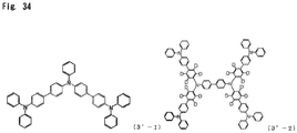
- the triarylamine compound represented by the general formula (3) or the general formula (4) expresses high hole mobility.
- such a triarylamine compound having a specific structure is combined, as a material for the first hole transport layer, with a material for the second hole transport layer, whereby holes can be injected and transported more efficiently into the luminous layer, and a more elaborate carrier balance is achieved. Consequently, the luminous efficiency is further improved, and the driving voltage further declines, so that the durability is further improved.
- an organic EL device having a high efficiency, working at a low driving voltage, and possessing a particularly long lifetime has been realized.
- the organic EL device of the present invention has a basic structure in which an anode, a first hole transport layer, a second hole transport layer, a luminous layer, an electron transport layer, and a cathode are provided in this order on a substrate such as a glass substrate or a transparent plastic substrate (e.g., polyethylene terephthalate substrate).
- a substrate such as a glass substrate or a transparent plastic substrate (e.g., polyethylene terephthalate substrate).
- the organic EL device of the present invention has such a basic structure
- its layer structure can take various forms. For example, it is possible to provide a hole injection layer between the anode and the first hole transport layer, provide an electron blocking layer between the second hole transport layer and the luminous layer, provide a hole blocking layer between the luminous layer and the electron transport layer, or provide an electron injection layer between the electron transport layer and the cathode.
- some organic layers can be omitted, or the roles of some organic layers can be fulfilled by any other layer. For example, a layer concurrently serving as the hole injection layer and the first hole transport layer can be formed, or a layer concurrently serving as the electron injection layer and the electron transport layer can be formed.
- a configuration in which two or more organic layers having the same function are laminated can be adopted.
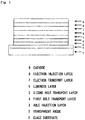
- Fig. 1 shows a layer configuration adopted in the Examples to be described later, namely, a layer configuration in which a transparent anode 2, a hole injection layer 3, a first hole transport layer 4, a second hole transport layer 5, a luminous layer 6, an electron transport layer 7, an electron injection layer 8, and a cathode 9 are formed in this order on a glass substrate 1.
- the present invention is prominently characterized in that the second hole transport layer contains an arylamine compound represented by the general formula (1) (may hereinafter be referred to as "arylamine compound I”), and that the electron transport layer contains a pyrimidine derivative represented by the general formula (2) (may hereinafter be referred to as "pyrimidine derivative II").
- arylamine compound I an arylamine compound represented by the general formula (1)
- pyrimidine derivative II may hereinafter be referred to as "pyrimidine derivative II”
- the arylamine compound I contained in the second hole transport layer has a structure represented by the following general formula (1):
- n1 denotes an integer of 1 to 4.
- Ar 1 , Ar 2 , Ar 3 and Ar 4 may be identical or different, and each represents an aromatic hydrocarbon group, an aromatic heterocyclic group, or a condensed polycyclic aromatic group.
- the condensed polycyclic aromatic group does not have a heteroatom (e.g., a nitrogen atom, an oxygen atom, or a sulfur atom) in its skeleton.
- Examples of the aromatic hydrocarbon group, the aromatic heterocyclic group, or the condensed polycyclic aromatic group, represented by Ar 1 to Ar 4 include a phenyl group, a biphenylyl group, a terphenylyl group, a naphthyl group, an anthracenyl group, a phenanthrenyl group, a fluorenyl group, a spirobifluorenyl group, an indenyl group, a pyrenyl group, a perylenyl group, a fluoranthenyl group, a triphenylenyl group, a pyridyl group, a furyl group, a pyrrolyl group, a thienyl group, a quinolyl group, an isoquinolyl group, a benzofuranyl group, a benzothienyl group, an indolyl group, a carbazolyl group, a benzoxazolyl group, a
- Ar 1 to Ar 4 may be present independently of each other without forming a ring. However, Ar 1 and Ar 2 , or Ar 3 and Ar 4 may bind to each other via a single bond, a substituted or unsubstituted methylene group, an oxygen atom, or a sulfur atom to form a ring.
- the aromatic heterocyclic group represented by Ar 1 to Ar 4
- the aromatic hydrocarbon group or condensed polycyclic aromatic group illustrated above is preferred.
- the aromatic hydrocarbon group, the aromatic heterocyclic group, or the condensed polycyclic aromatic group, represented by Ar 1 to Ar 4 may be unsubstituted or may have a substituent.
- the substituent can be exemplified by the following groups, in addition to a deuterium atom, a cyano group, and a nitro group:
- an aromatic hydrocarbon group, an oxygen-containing aromatic heterocyclic group, or a condensed polycyclic aromatic group is preferred, and a phenyl group, a biphenylyl group, a terphenylyl group, a naphthyl group, a phenanthrenyl group, a triphenylenyl group, a fluorenyl group, a dibenzofuranyl group, or a fluoranthenyl group is more preferred.
- Ar 1 and Ar 2 be different groups, or that Ar 3 and Ar 4 be different groups. It is more preferred that Ar 1 and Ar 2 be different groups, and that Ar 3 and Ar 4 be different groups.
- a deuterium atom As the substituent optionally possessed by the aromatic hydrocarbon group, aromatic heterocyclic group, or condensed polycyclic aromatic group, represented by Ar 1 to Ar 4 , a deuterium atom, an alkyl group having 1 to 6 carbon atoms, an alkenyl group having 2 to 6 carbon atoms, an aryloxy group, an aromatic hydrocarbon group, a nitrogen-containing aromatic heterocyclic group, an oxygen-containing aromatic heterocyclic group, or a condensed polycyclic aromatic group is preferred, and a deuterium atom, a phenyl group, a biphenylyl group, a naphthyl group, a dibenzofuranyl group, or a vinyl group is more preferred. Formation of a condensed aromatic ring upon binding of the substituents via a single bond is also preferred.
- n1 1 to 3 is preferred, and 1 or 2 is more preferred.
- a mode in which all the bonds are 1,4-bonds is not preferred, but a mode in which at least one 1,2-bond or 1,3-bond is contained is preferred, from the viewpoint of thin film stability which influences the device lifetime.
- the phenylene groups are all bound by 1,4-bonds, it is preferred, as in Compound 1-94, that the phenylene group be bound at the ortho-position or the meta-position with respect to -NAr 1 Ar 2 in the benzene ring to which the -NAr 1 Ar 2 is bound, and that the phenylene group be bound at the ortho-position or the meta-position with respect to -NAr 3 Ar 4 in the benzene ring to which the -NAr 3 Ar 4 is bonded.
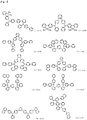
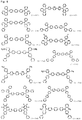
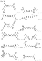
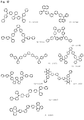
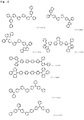
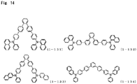
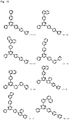
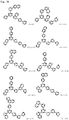
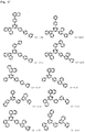
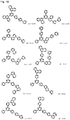
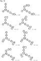
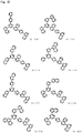
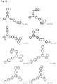
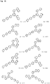
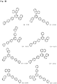
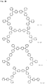
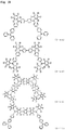
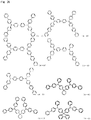
- arylamine compounds I the compounds suitably used in the organic EL device of the present invention are concretely exemplified in Figs. 2 to 14 .
- the arylamine compounds I are not limited to these compounds.
- D stands for deuterium.
- the arylamine compound I can be produced by a publicly known method such as Suzuki coupling.
- the pyrimidine derivative II contained in the electron transport layer is represented by the following general formula (2) :
- the pyrimidine derivative II is broadly classified into the following two forms in accordance with the positional relationship between -Ar 7 and -A 1 -A 2 -A 3 -B:
- Ar 5 and Ar 6 may be identical or different, and each represents an aromatic hydrocarbon group, an aromatic heterocyclic group, or a condensed polycyclic aromatic group.
- Ar 7 represents a hydrogen atom, an aromatic hydrocarbon group, an aromatic heterocyclic group, or a condensed polycyclic aromatic group.
- Ar 5 and Ar 7 may be identical or different, and Ar 6 and Ar 7 may be identical or different.
- Examples of the aromatic hydrocarbon group, the aromatic heterocyclic group, or the condensed polycyclic aromatic group, represented by Ar 5 to Ar 7 include a phenyl group, a biphenylyl group, a terphenylyl group, a tetrakisphenyl group, a styryl group, a naphthyl group, an anthracenyl group, an acenaphthenyl group, a phenanthrenyl group, a fluorenyl group, an indenyl group, a pyrenyl group, a perylenyl group, a fluoranthenyl group, a triphenylenyl group, a spirobifluorenyl group, a furyl group, a thienyl group, a benzofuranyl group, a benzothienyl group, a dibenzofuranyl group, and a dibenzothienyl group.
- the aromatic hydrocarbon group, the aromatic heterocyclic group, or the condensed polycyclic aromatic group, represented by Ar 5 to Ar 7 may be unsubstituted or may have a substituent.
- the substituent can be exemplified by the following groups, in addition to a deuterium atom, a cyano group, and a nitro group:
- the alkyl group having 1 to 6 carbon atoms, the alkenyl group, and the alkyloxy group having 1 to 6 carbon atoms may be a straight-chain or branched. Any of these substituents may be unsubstituted or may be further substituted by the above exemplary substituent. Furthermore, these substituents may be present independently of each other so as not to form a ring. However, they may bind to each other via a single bond, a substituted or unsubstituted methylene group, an oxygen atom, or a sulfur atom to form a ring. Any of these substituents, and Ar 5 , Ar 6 or Ar 7 to which the substituent is bound may bind to each other via an oxygen atom or a sulfur atom to form a ring.
- a 1 and A 2 may be identical or different, and each represents a divalent group of an aromatic hydrocarbon, or a divalent group of a condensed polycyclic aromatic.
- a 3 represents a single bond.
- the divalent group of an aromatic hydrocarbon, or the divalent group of a condensed polycyclic aromatic represents a divalent group formed by removing two hydrogen atoms from an aromatic hydrocarbon or a condensed polycyclic aromatic.
- the aromatic hydrocarbon or the condensed polycyclic aromatic include benzene, biphenyl, terphenyl, tetrakisphenyl, styrene, naphthalene, anthracene, acenaphthalene, fluorene, phenanthrene, indane, pyrene, triphenylene, and spirobifluorene.
- the divalent group of an aromatic hydrocarbon, or the divalent group of a condensed polycyclic aromatic, represented by Ar 1 may be unsubstituted or may have a substituent.
- substituents are the same as those shown as the substituents that may be possessed by the aromatic hydrocarbon group, the aromatic heterocyclic group, or the condensed polycyclic aromatic group represented by Ar 5 to Ar 7 above. The same holds true of the embodiments that the substituents can adopt.
- B represents an aromatic heterocyclic group.
- the aromatic heterocyclic group represented by B include a triazinyl group, a pyridyl group, a pyrimidinyl group, a furyl group, a pyrrolyl group, a thienyl group, a quinolyl group, an isoquinolyl group, a benzofuranyl group, a benzothienyl group, an indolyl group, a carbazolyl group, a benzoxazolyl group, a benzothiazolyl group, a quinoxalinyl group, a benzimidazolyl group, a pyrazolyl group, a dibenzofuranyl group, a dibenzothienyl group, an azafluorenyl group, a diazafluorenyl group, a naphthyridinyl group, a phenanthrolinyl group, an acridinyl group, a carbolin
- the aromatic heterocyclic group, represented by B may be unsubstituted or may have a substituent.
- substituents are the same as those shown as the substituents that may be possessed by the aromatic hydrocarbon group, the aromatic heterocyclic group, or the condensed polycyclic aromatic group represented by Ar 5 to Ar 7 . The same holds true of the embodiments that the substituent can adopt.
- a phenyl group preferred is a phenyl group; a biphenylyl group; a naphthyl group; an anthracenyl group; an acenaphthenyl group; a phenanthrenyl group; a fluorenyl group; an indenyl group; a pyrenyl group; a perylenyl group; a fluoranthenyl group; a triphenylenyl group; a spirobifluorenyl group; an oxygen-containing aromatic heterocyclic group, for example, a furyl group, a benzofuranyl group, or a dibenzofuranyl group; or a sulfur-containing aromatic heterocyclic group, for example, a thienyl group, a benzothienyl group, or a dibenzothienyl group.
- a phenyl group More preferred is a phenyl group, a biphenylyl group, a naphthyl group, a phenanthrenyl group, a fluorenyl group, a pyrenyl group, a fluoranthenyl group, a triphenylenyl group, a spirobifluorenyl group, a dibenzofuranyl group, or a dibenzothienyl group.
- Ar 5 is a phenyl group
- a phenyl group preferably has, as a substituent, a condensed polycyclic aromatic group or an unsubstituted phenyl group, and more preferably has, as a substituent, a naphthyl group, a phenanthrenyl group, a pyrenyl group, a fluoranthenyl group, a triphenylenyl group, a spirobifluorenyl group, or an unsubstituted phenyl group. It is also preferred for the substituent and the phenyl group to bind to each other via an oxygen atom or a sulfur atom, thereby forming a ring.
- a phenyl group having a substituent is preferred.
- an aromatic hydrocarbon group for example, a phenyl group, a biphenylyl group, or a terphenyl group
- a condensed polycyclic aromatic group for example, a naphthyl group, an anthracenyl group, an acenaphthenyl group, a phenanthrenyl group, a fluorenyl group, an indenyl group, a pyrenyl group, a perylenyl group, a fluoranthenyl group, a triphenylenyl group, or a spirobifluorenyl group
- an oxygen-containing aromatic heterocyclic group for example, a furyl group, a benzofuranyl group, or a dibenzofuranyl group
- a sulfur-containing aromatic heterocyclic group for example, a thieny
- a phenyl group More preferred is a phenyl group, a naphthyl group, an anthracenyl group, a phenanthrenyl group, a fluorenyl group, a pyrenyl group, a fluoranthenyl group, a triphenylenyl group, a spirobifluorenyl group, a dibenzofuranyl group, or a dibenzothienyl group. It is also preferred for the substituent and the phenyl group to bind to each other via an oxygen atom or a sulfur atom, thereby forming a ring.
- Ar 6 is a spirobifluorenyl group; an oxygen-containing aromatic heterocyclic group, for example, a furyl group, a benzofuranyl group, or a dibenzofuranyl group; or a sulfur-containing aromatic heterocyclic group, for example, a thienyl group, a benzothienyl group, or a dibenzothienyl group.
- a hydrogen atom As Ar 7 , preferred is a hydrogen atom; a spirobifluorenyl group; an oxygen-containing aromatic heterocyclic group, for example, a furyl group, a benzofuranyl group, or a dibenzofuranyl group; or a sulfur-containing aromatic heterocyclic group, for example, a thienyl group, a benzothienyl group, or a dibenzothienyl group; or a phenyl group having a substituent, and a hydrogen atom is more preferred.
- an oxygen-containing aromatic heterocyclic group for example, a furyl group, a benzofuranyl group, or a dibenzofuranyl group
- a sulfur-containing aromatic heterocyclic group for example, a thienyl group, a benzothienyl group, or a dibenzothienyl group
- a phenyl group having a substituent and a hydrogen atom is more preferred.
- the substituent that the phenyl group has preferred is an aromatic hydrocarbon group, for example, a phenyl group, a biphenylyl group, or a terphenyl group; a condensed polycyclic aromatic group, for example, a naphthyl group, an anthracenyl group, an acenaphthenyl group, a phenanthrenyl group, a fluorenyl group, an indenyl group, a pyrenyl group, a perylenyl group, a fluoranthenyl group, a triphenylenyl group, or a spirobifluorenyl group; an oxygen-containing aromatic heterocyclic group, for example, a furyl group, a benzofuranyl group, or a dibenzofuranyl group; or a sulfur-containing aromatic heterocyclic group, for example, a thienyl group, a benzothienyl group, or a dibenzothione
- a phenyl group More preferred is a phenyl group, a naphthyl group, an anthracenyl group, a phenanthrenyl group, a fluorenyl group, a pyrenyl group, a fluoranthenyl group, a triphenylenyl group, a spirobifluorenyl group, a dibenzofuranyl group, or a dibenzothienyl group. It is also preferred for the substituent and the phenyl group to bind to each other via an oxygen atom or a sulfur atom, thereby forming a ring.
- Ar 5 and Ar 6 be different groups. Since good symmetry of the entire molecule may facilitate crystallization, it is preferred, from the viewpoint of thin film stability, that Ar 6 and Ar 7 be different groups. Cases where "Ar 5 and Ar 6 are different groups" and cases where “Ar 6 and Ar 7 are different groups” include an embodiment in which the positions of binding to the pyrimidine ring are different, an embodiment in which different substituents are present, and an embodiment in which the positions of binding of the substituents are different.
- a 1 and A 2 a divalent group formed by removing two hydrogen atoms from benzene, biphenyl, naphthalene, anthracene, fluorene, or phenanthrene is preferred, and a divalent group formed by removing two hydrogen atoms from benzene or naphthalene is more preferred,
- a 1 and A 2 are a divalent group formed by removing two hydrogen atoms from benzene (namely, a phenylene group), and the other is a divalent group formed by removing two hydrogen atoms from naphthalene (namely, a naphthylene group), or an embodiment in which both of A 1 and A 2 are phenylene groups.
- the sublimation temperature does not become too high when an organic EL device is produced by the vacuum deposition method.
- a 3 a single bond is preferred, because the sublimation temperature does not become too high when an organic EL device is produced by vacuum deposition.
- a nitrogen-containing aromatic heterocyclic group for example, a triazinyl group, a pyridyl group, a pyrimidinyl group, a pyrrolyl group, a quinolyl group, an isoquinolyl group, an indolyl group, a carbazolyl group, a benzoxazolyl group, a benzothiazolyl group, a quinoxalinyl group, a benzimidazolyl group, a pyrazolyl group, an azafluorenyl group, a diazafluorenyl group, a naphthyridinyl group, a phenanthrolinyl group, an acridinyl group, a carbolinyl group, an azaspirobifluorenyl group, or a diazaspirobifluorenyl group is preferred; a triazinyl group, a pyridyl group, a pyrimidiny
- pyrimidine derivative II Preferred examples of the pyrimidine derivative II are shown in Figs. 15 to 29 , but the pyrimidine derivative II is not limited to these compounds.
- Compounds 2-1 to 2-122 correspond to the aforementioned general formula (2a).
- Compounds 2-123 to 2-126 correspond to the aforementioned general formula (2b).
- the pyrimidine derivative II can be synthesized in accordance with a publicly known method (see Patent Document 6) .
- the purification of the arylamine compound I and the pyrimidine derivative II can be performed, for example, by purification using a column chromatograph, adsorption purification using silica gel, activated carbon, activated clay, or the like, or recrystallization or crystallization using a solvent. Purification by sublimation purification or the like may be performed in the final stage.
- the identification of the compounds can be made by NMR analysis. As the physical properties, the glass transition point (Tg) and the work function can be measured.
- the glass transition point (Tg) serves as an index to stability in a thin film state.
- the glass transition point (Tg) can be measured using a powder and a high sensitivity differential scanning calorimeter (DSC3100S, produced by Bruker AXS).
- the work function serves as an index to hole transport properties.
- the work function can be measured by preparing a 100 nm thin film on an ITO substrate, and making a measurement using an ionization potential measuring device (PYS-202, produced by Sumitomo Heavy Industries, Ltd.).
- the respective layers can take various forms, as long as they fulfill the conditions that the arylamine compound I is contained in the second hole transport layer and that the pyrimidine derivative II is contained in the electron transport layer.
- the respective layers will be described in detail below by reference to Fig. 1 .
- the anode 2 is provided on the transparent substrate 1.
- An electrode material having a high work function, such as ITO or gold, is used as the anode 2.
- the hole injection layer 3 may be provided, if necessary, between the anode 2 and the hole transport layer 4.
- a publicly known material may be used for the hole injection layer 3.
- the aforementioned arylamine compound I, a triarylamine compound III represented by a general formula (3) described later, or a triarylamine compound IV represented by a general formula (4) described later may be used, because their hole mobility is high. If the triarylamine compound III or IV is used in the hole injection layer 3, the composition of the hole injection layer 3 and the composition of the first hole transport layer 4 to be described later have to be different.
- Examples of usable and publicly known materials are materials such as starburst triphenylamine derivatives and various triphenylamine tetramers; porphyrin compounds typified by copper phthalocyanine; acceptor type heterocyclic compounds such as hexacyanoazatriphenylene; and coating type polymeric materials.
- these materials may each be subjected to film formation, or any of them may be mixed with other of them and the resulting mixture may be subjected to film formation.
- the materials for general use in the hole injection layer may be further p-doped with tris(bromophenyl)aminium hexachloroantimonate or radialene derivatives (see WO2014/009310 ), and may be used in the hole injection layer.
- Polymeric compounds containing the structures of benzidine derivatives such as TPD in their partial structures may also be used in the hole injection layer.
- the hole injection layer 3 can be obtained.
- a publicly known method such as vapor deposition, spin coating or ink jetting with the use of any of the above materials
- the hole injection layer 3 can be obtained.
- Each of the layers described below can similarly be obtained by thin film formation performed using a publicly known method such as vapor deposition, spin coating, or ink jetting.
- the first hole transport layer 4 is provided between the above anode 2 (or hole injection layer 3) and the second hole transport layer 5.
- a publicly known material as exemplified below can be incorporated into the first hole transport layer 4.
- the triarylamine compounds having 3 to 6 triarylamine structures in the molecule are used preferably.
- the triarylamine compounds having 2 triarylamine structures in the molecule are used preferably.
- the triarylamine compounds having 2 triarylamine structures include an embodiment in which the two benzene rings in the triarylamine structure are linked via a single bond, namely, an embodiment having a carbazole ring structure, as in 4'-1 and 4'-2 of Fig. 38 .
- triarylamine compounds having 3 to 6 triarylamine structures triarylamine compounds III having 4 triarylamine structures, represented by the general formula (3) described below, are preferred. The reason is that they are excellent in thin film stability and heat resistance in addition to hole transport properties, and they are can be synthesized easily.
- triarylamine compounds IV represented by the general formula (4) described below are preferred, because they are excellent in thin film stability and heat resistance in addition to hole transport properties, and they can be synthesized easily.
- Triarylamine compound III represented by the following general formula (3):
- R 1 to R 12 may be identical or different, and each represents a deuterium atom, a fluorine atom, a chlorine atom, a cyano group, a nitro group, an alkyl group having 1 to 6 carbon atoms, a cycloalkyl group having 5 to 10 carbon atoms, an alkenyl group having 2 to 6 carbon atoms, an alkyloxy group having 1 to 6 carbon atoms, a cycloalkyloxy group having 5 to 10 carbon atoms, an aromatic hydrocarbon group, an aromatic heterocyclic group, a condensed polycyclic aromatic group, or an aryloxyl group.
- the alkyl group having 1 to 6 carbon atoms, the alkenyl group having 2 to 6 carbon atoms, and the alkyloxy group having 1 to 6 carbon atoms may be a straight-chain or branched.
- the alkyl group having 1 to 6 carbon atoms, the cycloalkyl group having 5 to 10 carbon atoms, or the alkenyl group having 2 to 6 carbon atoms, represented by R 1 to R 12 can be exemplified by a methyl group, an ethyl group, an n-propyl group, an isopropyl group, an n-butyl group, an isobutyl group, a tert-butyl group, an n-pentyl group, an isopentyl group, a neopentyl group, an n-hexyl group, a cyclopentyl group, a cyclohexyl group, a 1- adamantyl group, a 2-adamantyl group, a vinyl group, an allyl group, an isopropenyl group, or a 2-butenyl group.
- the alkyl group having 1 to 6 carbon atoms, the cycloalkyl group having 5 to 10 carbon atoms, or the alkenyl group having 2 to 6 carbon atoms, represented by R 1 to R 12 may be unsubstituted or may have a substituent.
- the substituent can be exemplified by the following groups, in addition to a deuterium atom, a cyano group, and a nitro group:
- the alkenyl group and the alkyloxy group having 1 to 6 carbon atoms may be a straight-chain or branched. Any of these substituents may be unsubstituted or may be further substituted by the above exemplary substituent. Moreover, these substituents may be present independently of each other without forming a ring. However, they may bind to each other via a single bond, a substituted or unsubstituted methylene group, an oxygen atom, or a sulfur atom to form a ring.
- the alkyloxy group having 1 to 6 carbon atoms or the cycloalkyloxy group having 5 to 10 carbon atoms, represented by R 1 to R 12 can be exemplified by a methyloxy group, an ethyloxy group, an n-propyloxy group, an isopropyloxy group, an n-butyloxy group, a tert-butyloxy group, an n-pentyloxy group, an n-hexyloxy group, a cyclopentyloxy group, a cyclohexyloxy group, a cycloheptyloxy group, a cyclooctyloxy group, a 1-adamantyloxy group, and a 2-adamantyloxy group.
- These groups may be unsubstituted or may have a substituent.
- substituents are the same as those shown as the substituents that may be possessed by the alkyl group having 1 to 6 carbon atoms, the cycloalkyl group having 5 to 10 carbon atoms, or the alkenyl group having 2 to 6 carbon atoms, represented by R 1 to R 12 . The same holds true of the forms that the substituents can take.
- the aromatic hydrocarbon group, the aromatic heterocyclic group, or the condensed polycyclic aromatic group, represented by R 1 to R 12 can be the same as those exemplified as the aromatic hydrocarbon group, the aromatic heterocyclic group, or the condensed polycyclic aromatic group represented by Ar 1 to Ar 4 in the aforementioned general formula (1).
- substituents may be unsubstituted or may have a substituent.
- the substituent can be exemplified by the same ones as those shown as the substituents that may be possessed by the aromatic hydrocarbon group, the aromatic heterocyclic group, or the condensed polycyclic aromatic group represented by Ar 1 to Ar 4 in the general formula (1). The same holds true of the forms that the substituents can take.
- the aryloxy group represented by R 1 to R 12 can be exemplified by a phenyloxy group, a biphenylyloxy group, a terphenylyloxy group, a naphthyloxy group, an anthracenyloxy group, a phenanthrenyloxy group, a fluorenyloxy group, an indenyloxy group, a pyrenyloxy group, and a perylenyloxy group.
- the aryloxy group may be unsubstituted or may have a substituent.
- the substituent can be exemplified by the same ones as those shown as the substituents that may be possessed by the aromatic hydrocarbon group, the aromatic heterocyclic group, or the condensed polycyclic aromatic group, represented by Ar 1 to Ar 4 in the general formula (1). The same holds true of the forms that the substituents can take.
- r 1 to r 12 respectively show the numbers of the groups R 1 s to R 12 s bound to the aromatic ring.
- r 1 , r 2 , r 5 , r 8 , r 11 and r 12 each denotes an integer of 0 to 5, while r 3 , r 4 , r 6 , r 7 , r 9 and r 10 each denotes an integer of 0 to 4. If r 1 to r 12 are 0, this means that none of R 1 to R 12 is present on the aromatic rings. That is, the aromatic rings are not substituted by the groups represented by R 1 to R 12 .
- a plurality of R 1 s to R 12 s are bound to the same aromatic ring.
- the bound groups may be identical or different. Moreover, they may be present independently of each other without forming a ring, but they may bind to each other via a single bond, a substituted or unsubstituted methylene group, an oxygen atom, or a sulfur atom to form a ring.
- a plurality of substituents (2 vinyl groups) are bound together via a single bond to form a naphthalene ring.
- L 1 to L 3 each is a bridge group linking the two triarylamine structures.
- L 1 to L 3 may be identical or different, and each represents a single bond, or a divalent group represented by any of the following structural formulas (B) to (G) :
- n2 denotes an integer of 1 to 3.
- the divalent groups represented by the structural formulas (B) to (G) each may be unsubstituted or may be substituted by deuterium.
- a deuterium atom, an alkyl group having 1 to 6 carbon atoms, an alkenyl group having 2 to 6 carbon atoms, an aromatic hydrocarbon group, or a condensed polycyclic aromatic group is preferred, and a deuterium atom, a phenyl group, a biphenylyl group, a naphthyl group, or a vinyl group is more preferred. Formation of a condensed aromatic ring upon binding of these groups via a single bond is also preferred, as in 3-8 of Fig.31 .
- a deuterium atom, a phenyl group, or a biphenylyl group is preferred in particular.
- an integer of 0 to 3 is preferred, and an integer of 0 to 2 is more preferred.
- L 1 to L 3 a divalent group represented by the structural formula (B) or (D), or a single bond is preferred.
- a divalent group represented by the structural formula (B), or a single bond is more preferred.
- n2 in the structural formula (B) 1 or 2 is preferred, and 1 is more preferred.
- triarylamine compound III Preferred examples of the triarylamine compound III are shown in Figs. 30 to 33 , but the triarylamine compounds III are not limited to these compounds.
- D represents a deuterium atom.
- triarylamine compounds having 3 to 6 triarylamine structures in the molecule which are preferably used in the organic EL device of the present invention
- preferred examples of the triarylamine compounds other than the triarylamine compounds III are shown in Fig. 34 .
- the triarylamine compounds are not limited to these compounds.
- D represents a deuterium atom.
- the triarylamine compound III can be synthesized in accordance with a publicly known method (see Patent Documents 7 to 9).
- Triarylamine compound IV represented by the following general formula (4):
- R 13 to R 18 may be identical or different, and each represents a deuterium atom, a fluorine atom, a chlorine atom, a cyano group, a nitro group, an alkyl group having 1 to 6 carbon atoms, a cycloalkyl group having 5 to 10 carbon atoms, an alkenyl group having 2 to 6 carbon atoms, an alkyloxy group having 1 to 6 carbon atoms, a cycloalkyloxy group having 5 to 10 carbon atoms, an aromatic hydrocarbon group, an aromatic heterocyclic group, a condensed polycyclic aromatic group, or an aryloxyl group.
- the alkyl group having 1 to 6 carbon atoms, the alkenyl group having 2 to 6 carbon atoms, and the alkyloxy group having 1 to 6 carbon atoms may be a straight-chain or branched.
- the alkyl group having 1 to 6 carbon atoms, the cycloalkyl group having 5 to 10 carbon atoms, or the alkenyl group having 2 to 6 carbon atoms, represented by R 13 to R 18 can be exemplified by the same as that shown as the alkyl group having 1 to 6 carbon atoms, the cycloalkyl group having 5 to 10 carbon atoms, or the alkenyl group having 2 to 6 carbon atoms, represented by R 1 to R 12 in the general formula (3).
- These groups may be unsubstituted or may have a substituent.
- substituents are the same as those shown as the substituents that may be possessed by the alkyl group having 1 to 6 carbon atoms, the cycloalkyl group having 5 to 10 carbon atoms, or the alkenyl group having 2 to 6 carbon atoms, represented by R 1 to R 12 in the general formula (3). The same holds true of the embodiments that the substituents can adopt.
- the alkyloxy group having 1 to 6 carbon atoms or the cycloalkyloxy group having 5 to 10 carbon atoms, represented by R 13 to R 18 , can be exemplified by the same as that shown as the alkyloxy group having 1 to 6 carbon atoms or the cycloalkyloxy group having 5 to 10 carbon atoms, represented by R 1 to R 12 in the general formula (3).
- These groups may be unsubstituted or may have a substituent.
- substituents are the same as those shown as the substituents that may be possessed by the alkyl group having 1 to 6 carbon atoms, the cycloalkyl group having 5 to 10 carbon atoms, or the alkenyl group having 2 to 6 carbon atoms, represented by R 1 to R 12 in the general formula (3). The same holds true of the forms that the substituents can take.
- the aromatic hydrocarbon group, the aromatic heterocyclic group, or the condensed polycyclic aromatic group, represented by R 13 to R 18 can be the same as that shown as the aromatic hydrocarbon group, the aromatic heterocyclic group, or the condensed polycyclic aromatic group represented by Ar 1 to Ar 4 in the aforementioned general formula (1).
- substituents may be unsubstituted or may have a substituent.
- the substituent can be exemplified by the same ones as those shown as the substituents that may be possessed by the aromatic hydrocarbon group, the aromatic heterocyclic group, or the condensed polycyclic aromatic group represented by Ar 1 to Ar 4 in the general formula (1). The same holds true of the forms that the substituents can take.
- the aryloxy group represented by R 13 to R 18 can be exemplified by the same as that shown as the aryloxy group represented by R 1 to R 12 in the general formula (3).
- the aryloxy group may be unsubstituted or may have a substituent.
- the substituent can be exemplified by the same ones as those shown as the substituents that may be possessed by the aromatic hydrocarbon group, the aromatic heterocyclic group, or the condensed polycyclic aromatic group, represented by Ar 1 to Ar 4 in the general formula (1). The same holds true of the forms that the substituents can take.
- r 13 to r 18 each shows the number of the groups R 13 s to R 18 s bound to the aromatic ring.
- r 13 , r 14 , r 17 and r 18 each denotes an integer of 0 to 5.
- r 15 and r 16 each denotes an integer of 0 to 4.
- r 13 to r 18 being 0 means that none of R 13 to R 18 is present on the aromatic rings. That is, the benzene rings are not substituted by the groups represented by R 13 to R 18 .
- r 13 , r 14 , r 17 and r 18 each is an integer of 2 to 5, or if r 15 and r 15 each is an integer of 2 to 4, a plurality of R 13 s to R 18 s are bound to the same aromatic ring.
- the bound groups may be identical or different. Moreover, they may be present independently of each other without forming a ring, but may bind to each other via a single bond, a substituted or unsubstituted methylene group, an oxygen atom, or a sulfur atom to form a ring.
- a plurality of substituents (2 vinyl groups) are bound together via a single bond to form a naphthalene ring.
- L 4 is a bridge group linking the two triarylamine structures.
- L 4 represents a single bond, or a divalent group represented by any of the aforementioned structural formulas (C) to (G).
- a deuterium atom, a chlorine atom, an alkyl group having 1 to 6 carbon atoms, an alkenyl group having 2 to 6 carbon atoms, an aromatic hydrocarbon group, a nitrogen-containing aromatic heterocyclic group, or a condensed polycyclic aromatic group is preferred, and a deuterium atom, a phenyl group, a biphenylyl group, a naphthyl group, or a vinyl group is more preferred. Formation of a condensed aromatic ring upon binding of these groups via a single bond, as in Compounds 4-13 and 4-14 of Fig. 36 , is also preferred. A deuterium atom, a phenyl group, or a biphenylyl group is preferred in particular.
- an integer of 0 to 3 is preferred, and an integer of 0 to 2 is more preferred.
- L 4 a divalent group represented by the structural formula (D) or (G), or a single bond is preferred.
- triarylamine compound IV Preferred examples of the triarylamine compound IV are shown in Figs. 35 to 37 , but the triarylamine compounds IV are not limited to these compounds.
- D represents a deuterium atom.
- triarylamine compounds having 2 triarylamine structures which are preferably used in the organic EL device of the present invention
- examples of the triarylamine compounds other than the triarylamine compounds IV are shown in Fig. 38 .
- the triarylamine compounds are not limited to these compounds.
- the triarylamine compound IV can be synthesized in accordance with a publicly known method (see Patent Documents 7 to 9).
- the above-mentioned materials may be subjected singly to film formation, or any of which may be mixed with other of them and subjected to film formation.
- the first hole transport layer 4 may have a structure in which layers each formed from any one of these materials are stacked; a structure in which layers each formed from a mixture of these materials are stacked; or a structure in which a layer of a single material and a layer of a mixture thereof are stacked.
- the material usually used for the layer can be further p-doped with tris(bromophenyl)aminium hexachloroantimonate or a radialene derivative (see, for example, WO2014/009310 ), or a polymeric compound containing the structure of a benzidine derivative such as TPD in its partial structure can be used.
- a coating type polymeric material such as poly(3,4-ethylenedioxythiophene) (PEDOT)/poly(styrene sulfonate) (PSS) can be used.
- PEDOT poly(3,4-ethylenedioxythiophene)
- PSS poly(styrene sulfonate)
- the second hole transport layer 5 is provided between the first hole transport layer 4 and the luminous layer 6, and the arylamine compound I is used for such a second hole transport layer 5.
- a publicly known material with hole transport properties may be used concurrently, as long as this material does not impair the effects of the present invention.
- Examples of the publicly known material with hole transport properties include the same ones as those illustrated in connection with the first hole transport layer 4. These materials may be subjected singly to film formation, or any of them may be mixed with other of them and subjected to film formation.
- the second hole transport layer 5 may have a structure in which layers each formed from any one of these materials are stacked; a structure in which layers each formed from a mixture of these materials are stacked; or a structure in which a layer of a single material and a layer of a mixture thereof are stacked.
- an electron blocking layer can be provided between the second hole transport layer 5 and the luminous layer 6, although this is not shown in Fig. 1 .
- the aforementioned arylamine compound I can be used from the viewpoint of its high electron blocking performance. If the arylamine compound I is used in the electron blocking layer, however, the composition of the electron blocking layer and the aforementioned composition of the second hole transport layer 5 have to be different. Alternatively, the triarylamine compound III or IV can be used.
- a publicly known compound having electron blocking action can be used.
- Examples of the publicly known compound having electron blocking action include the following:
- the electron blocking layer may have a structure in which layers each formed from any one of these materials are stacked; a structure in which layers each formed from a mixture of these materials are stacked; or a structure in which a layer of a single material and a layer of a mixture thereof are stacked.
- the luminous layer 6 is formed on the second hole transport layer 5 (or electron blocking layer) .
- the luminous layer 6 there can be used metal complexes of quinolinol derivatives including Alq 3 ; various metal complexes; anthracene derivatives; bisstyrylbenzene derivatives; pyrene derivatives; oxazole derivatives; and polyparaphenylenevinylene derivatives.
- the luminous layer 6 may be composed of a host material and a dopant material.
- a preferred example of the host material is an anthracene derivative.
- Other examples usable include the above luminescent materials; heterocyclic compounds having an indole ring as a partial structure of a condensed ring; heterocyclic compounds having a carbazole ring as a partial structure of a condensed ring; carbazole derivatives; thiazole derivatives; benzimidazole derivatives; and polydialkylfluorene derivatives.
- blue light emitting dopants such as pyrene derivatives; and amine derivatives having a fluorene ring as a partial structure of a condensed ring.
- Other materials usable include quinacridone, coumarin, rubrene, perylene, and derivatives thereof; benzopyran derivatives; indenophenanthrene derivatives; rhodamine derivatives; and aminostyryl derivatives.
- the electron blocking layer may have a structure in which layers each formed from any one of these materials are stacked; a structure in which layers each formed from a mixture of these materials are stacked; or a structure in which a layer of a single material and a layer of a mixture thereof are stacked.
- a phosphorescent luminous substance can be used as the luminescent material.
- a phosphorescent luminous substance in the form of a metal complex containing iridium, platinum or the like can be used.
- a green phosphorescent luminous substance such as Ir(ppy) 3 ; a blue phosphorescent luminous substance such as FIrpic or FIr 6 ; or a red phosphorescent luminous substance such as Btp 2 Ir(acac) may be used.
- the following hole inj ecting/transporting host material for example, can be used:
- a carbazole derivative for example, 4,4'-di(N-carbazolyl)biphenyl (CBP), TCTA, or mCP.
- the following electron transporting host material is also usable: p-bis(triphenylsilyl)benzene (UGH2), or 2,2',2"-(1,3,5-phenylene)-tris(1-phenyl-1H-benzimidazole)
- a high performance organic EL device By using such a host material, a high performance organic EL device can be prepared.
- Doping of the host material with the phosphorescent luminous substance is preferably performed by codeposition in a range of 1 to 30% by weight based on the entire luminous layer in order to avoid concentration quenching.
- a material which emits delayed fluorescence such as a CDCB derivative, for example, PIC-TRZ, CC2TA, PXZ-TRZ, or 4CzIPN, can be used as the luminescent material.
- a hole blocking layer (not shown) can be provided between the luminous layer 6 and the electron transport layer 7.
- a publicly known compound having hole blocking action can be used for the hole blocking layer. Examples of the publicly known compound having hole blocking action include the following:
- the aforementioned pyrimidine derivative II is used for the electron transport layer 7.
- the pyrimidine derivative II the one represented by the general formula (2a) or (2b) is preferred, and the one represented by the general formula (2a) is more preferred.
- a publicly known material with electron transport properties may be used concurrently, as long as this material does not impair the effects of the present invention.
- the publicly known material with electron transport properties include metal complexes of quinolinol derivatives including Alq 3 and BAIq; various metal complexes; triazole derivatives; triazine derivatives; oxadiazole derivatives; pyridine derivatives; pyrimidine derivatives; benzimidazole derivatives; thiadiazole derivatives; anthracene derivatives; carbodiimide derivatives; quinoxaline derivatives; pyridoindole derivatives; phenanthroline derivatives; and silole derivatives.
- the hole blocking layer may have a structure in which layers each formed from any one of these materials are stacked; a structure in which layers each formed from a mixture of these materials are stacked; or a structure in which a layer of a single material and a layer of a mixture thereof are stacked.
- an alkali metal salt such as lithium fluoride or cesium fluoride
- an alkaline earth metal salt such as magnesium fluoride
- a metal oxide such as aluminum oxide.
- these materials can be omitted in the suitable selection of the electron transport layer and the cathode.
- an electrode material with a low work function such as aluminum, or an alloy having a lower work function, such as a magnesium-silver alloy, a magnesium-indium alloy, or an aluminum-magnesium alloy, is used as an electrode material.
- a nitrogen-purged reaction vessel was charged with 4,4"-dibromo-1,1':3',1"-terphenyl 8.81 g, 2-(phenylamino)-9,9-dimethyl-9H-fluorene 13.6 g, tert-butoxysodium 5.12 g, tris(dibenzylideneacetone)dipalladium 0.33 g, a 50% (w/v) toluene solution of tri-tert-butylphosphine 0.63 ml, and toluene 150 ml.
- the charged contents were heated, refluxed for 2 hours by stirring, and allowed to cool to prepare a reaction liquid.
- a nitrogen-purged reaction vessel was charged with N-(2-phenyl-biphenyl-4-yl)-N-phenylamine 13.1 g, 4,4"-diiodo-1,1':4',1"-terphenyl 20.0 g, copper powder 0.18 g, potassium carbonate 11.3 g, 3,5-di-tert-butylsalicylic acid 0.70 g, sodium bisulfite 0.86 g, and dodecylbenzene 30 ml.
- the charged contents were heated, stirred for 24 hours at 210°C, and allowed to cool, thereby obtaining a mixture.
- a nitrogen-purged reaction vessel was charged with N-phenyl-N- ⁇ 4-(4,4,5,5-tetramethyl-1,3,2-dioxaborolan-2-yl)phenyl ⁇ -(1,1'-biphenyl-4-yl)amine 18.2 g, 4,4'-diiodobiphenyl 7.5 g, a 2M aqueous solution of potassium carbonate 46 ml, toluene 60 ml, and ethanol 15 ml. A nitrogen gas was passed through the charged contents for 1 hour to obtain a mixture. To the mixture, 1.1 g of tetrakis(triphenylphosphine)palladium was added to obtain a reaction liquid.
- the reaction liquid was heated and stirred for 10 hours at 72°C.
- the reaction liquid after stirring was cooled to room temperature, and 60 ml of methanol was added thereto.
- Precipitated solids were collected by filtration, and washed with 100 ml of a methanol/water (5/1, v/v) mixed solution.
- 100 ml of 1, 2-dichlorobenzene was added to the solids after washing, and the solids were dissolved upon heating.
- the solution was allowed to cool and, upon addition of 200 ml of methanol, a crude product was precipitated.
- the precipitated crude product was collected by filtration.
- the crude product was subjected to reflux cleaning using 100 ml of methanol. As a result, 11.8 g (yield 81%) of Compound 1-93 was obtained as a pale yellow powder.
- a nitrogen-purged reaction vessel was charged with N-phenyl-N- ⁇ 4-(4,4,5,5-tetramethyl-1,3,2-dioxaborolan-2-yl)phenyl ⁇ -(1,1'-biphenyl-4-yl)amine 18.2 g, 3,4'-dibromobiphenyl 7.5 g, a 2M aqueous solution of potassium carbonate 46 ml, toluene 60 ml, and ethanol 15 ml. A nitrogen gas was passed through the charged contents for 1 hour to obtain a mixture. To the mixture, 1.1 g of tetrakis(triphenylphosphine)palladium was added to prepare a reaction liquid.
- the reaction liquid was heated and stirred for 10 hours at 72°C.
- the reaction liquid after stirring was cooled to room temperature, and 60 ml of methanol was added thereto.
- Precipitated solids were collected by filtration, and washed with 100 ml of a methanol/water (5/1, v/v) mixed solution.
- 100 ml of 1,2-dichlorobenzene was added to the solids, and the mixture was heated until the solids were dissolved. Insolubles were removed by filtration.
- the solution was allowed to cool and, upon addition of 200 ml of methanol, a crude product was precipitated.
- the precipitated crude product was collected by filtration.
- the crude product was subjected to reflux cleaning using 100 ml of methanol. As a result, 14.0 g (yield 84%) of Compound 1-130 was obtained as a pale yellow powder.
- the arylamine compound I had a glass transition point of 100°C or higher, demonstrating that it was stable in a thin film state.
- the arylamine compound I showed a suitable energy level as compared with a work function of 5.5 eV of an ordinary hole transport material such as NPD or TPD, and thus, it was found to have satisfactory hole transport capability.
- a nitrogen-purged reaction vessel was charged with 2-chloro-4-phenyl-6- ⁇ 4'-(pyridin-3-yl)biphenyl- 4-yl ⁇ pyrimidine 8.0 g, 4-biphenylboronic acid 3.8 g, tetrakistriphenylphosphine 0.44 g, potassium carbonate 7.9 g, toluene 80 ml, tetrahydrofuran 80 ml, and water 40 ml.
- the charged contents were heated, and stirred for 12 hours at 80°C to obtain a reaction liquid.
- the reaction liquid was cooled to room temperature, and an organic layer was collected by a liquid separating operation. The collected organic layer was concentrated under reduced pressure to obtain a crude product.
- a nitrogen-purged reaction vessel was charged with 2-chloro-4-(naphthyl-1-yl)-6- ⁇ 4'-(pyridin-3-yl)biphenyl-4-yl ⁇ pyrimidine 4.5 g, ⁇ 4-(naphthalen-1-yl)phenyl ⁇ boronic acid 2.61 g, tetrakistriphenylphosphine 0.22 g, potassium carbonate 3.97 g, toluene 45 ml, ethanol 11.3 ml, and water 14.4 ml.
- the charged contents were heated, and stirred for 12 hours at 70°C to obtain a reaction liquid.
- the reaction liquid was cooled to room temperature, and an organic stratum was collected by a liquid separating operation.
- the collected organic stratum was concentrated under reduced pressure to obtain a crude product.
- the crude product was purified by column chromatography (carrier: silica gel, eluting solution: ethyl acetate/heptane), and then purified by recrystallization using a toluene/acetone mixed solvent. As a result, 3.0 g (yield 49.2%) of Compound 2-16 was obtained as a white powder.
- the pyrimidine derivative II had a glass transition point of 100°C or higher, demonstrating that it was stable in a thin film state.
- the pyrimidine derivative II showed a greater value than a work function of 5.5 eV which an ordinary hole transport material such as NPD or TPD has. Thus, it was found to have high hole blocking capability.
- the hole injection layer 3, the first hole transport layer 4, the second hole transport layer 5, the luminous layer 6, the electron transport layer 7, the electron injection layer 8, and the cathode (aluminum electrode) 9 were vapor-deposited in this order on an ITO electrode formed beforehand as the transparent anode 2 on the glass substrate 1, thereby preparing an organic EL device as shown in Fig. 1 .
- the glass substrate 1 having a 150 nm thick ITO film formed thereon was ultrasonically cleaned in isopropyl alcohol for 20 minutes, and dried for 10 minutes on a hot plate heated at 200°C. Then, the glass substrate with the film was treated with UV ozone for 15 minutes, and mounted within a vacuum deposition machine. Then, the pressure inside the vacuum deposition machine was reduced to 0.001 Pa or lower.
- the hole injection layer 3 was formed.
- HIM-1 of the following structural formula was vapor-deposited so as to cover the transparent anode 2, thereby forming the hole injection layer 3 with a film thickness of 5 nm.
- the first hole transport layer 4 was formed.
- Compound 4-1 represented by the following structural formula was vapor-deposited on the hole injection layer 3 to form the first hole transport layer 4 with a film thickness of 60 nm.
- the second hole transport layer 5 was formed. Concretely, Compound 1-92 of Synthesis Example 3 was vapor-deposited on the first hole transport layer 4 to form the second hole transport layer 5 with a film thickness of 5 nm.
- the luminous layer 6 was formed.
- the electron transport layer 7 was formed.
- the electron injection layer 8 was obtained. Concretely, lithium fluoride was vapor deposited on the electron transport layer 7 to form the electron injection layer 8 with a film thickness of 1 nm.
- An organic EL device was prepared under the same conditions as in Device Example 1, except that the aforementioned Compound 4-1 was used, instead of Compound 1-92 of Synthesis Example 3, as the material for the second hole transport layer 5.
- the first hole transport layer 4 and the second hole transport layer 5 functioned as an integral hole transport layer (film thickness 65 nm).
- the device lifetime was measured. Concretely, the device lifetime was measured as the period of time required for the emission luminance to attenuate to 1900 cd/m 2 (corresponding to 95% relative to the initial luminance taken as 100%: 95% attenuation) when constant current driving was performed, with the emission luminance at the start of light emission (initial luminance) being set at 2000 cd/m 2 . The results are shown in Table 1.
- the luminous efficiency upon passage of a current at a current density of 10 mA/cm 2 was 6.35 cd/A in Device Comparative Example 2 using a publicly known electron transport material, while it was 7.95 cd/A, i. e. , the efficiency was higher in Device Comparative Example 1 using the pyrimidine derivative II.
- the luminous efficiency was 9.76 to 9.85 cd/A, i.e., the efficiencies were much higher.
- the power efficiency was 5.20 lm/W in Device Comparative Example 2 using a publicly known electron transport material, while it was 6.65 lm/W, i.e., the efficiency was higher in Device Comparative Example 1 using the pyrimidine derivative II.
- the power efficiency was 8.24 to 8.26 lm/W, i.e., the efficiencies were much higher.
- the device lifetime was 55 hours for the organic EL device of Device Comparative Example 2 using a publicly known electron transport material, while it was 83 hours, i.e., the lifetime was extended in Device Comparative Example 1 using the pyrimidine derivative II.
- the device lifetime was 116 to 150 hours, i.e., the lifetimes were further extended.
- the organic EL device of the present invention comprises a combination of the arylamine compound I having a specific structure and the pyrimidine derivative II having a specific structure so that holes and electrons can be efficiently injected into and transported to the luminous layer, thereby making it possible to realize an organic EL device with a high luminous efficiency and a long lifetime.
- the triarylamine compound III or IV having a specific structure as the material for the first hole transport layer, moreover, the material for the first hole transport layer and the material for the second hole transport layer provide a combination capable of injecting and transporting holes into the luminous layer more efficiently, namely, a combination of the materials with a more elaborate carrier balance.
- the organic EL device of the present invention has a higher luminous efficiency and a longer lifetime than conventional organic EL devices.
- the organic EL device of the present invention as described above, is increased in luminous efficiency, and greatly improved in durability.
- the organic EL device of the present invention can be put to uses such as domestic electrical appliances and illumination.
Landscapes
- Chemical & Material Sciences (AREA)
- Organic Chemistry (AREA)
- Physics & Mathematics (AREA)
- Engineering & Computer Science (AREA)
- Materials Engineering (AREA)
- Spectroscopy & Molecular Physics (AREA)
- Optics & Photonics (AREA)
- Electroluminescent Light Sources (AREA)
Applications Claiming Priority (2)
| Application Number | Priority Date | Filing Date | Title |
|---|---|---|---|
| JP2015187600 | 2015-09-25 | ||
| PCT/JP2016/077297 WO2017051765A1 (ja) | 2015-09-25 | 2016-09-15 | 有機エレクトロルミネッセンス素子 |
Publications (3)
| Publication Number | Publication Date |
|---|---|
| EP3355376A1 EP3355376A1 (en) | 2018-08-01 |
| EP3355376A4 EP3355376A4 (en) | 2019-05-22 |
| EP3355376B1 true EP3355376B1 (en) | 2021-12-01 |
Family
ID=58386584
Family Applications (1)
| Application Number | Title | Priority Date | Filing Date |
|---|---|---|---|
| EP16848553.0A Active EP3355376B1 (en) | 2015-09-25 | 2016-09-15 | Organic electroluminescent element |
Country Status (7)
| Country | Link |
|---|---|
| US (1) | US10950797B2 (zh) |
| EP (1) | EP3355376B1 (zh) |
| JP (1) | JP6807849B2 (zh) |
| KR (1) | KR102651208B1 (zh) |
| CN (1) | CN108292708B (zh) |
| TW (1) | TWI704210B (zh) |
| WO (1) | WO2017051765A1 (zh) |
Families Citing this family (4)
| Publication number | Priority date | Publication date | Assignee | Title |
|---|---|---|---|---|
| US11043639B2 (en) | 2018-12-28 | 2021-06-22 | Samsung Electronics Co., Ltd. | Charge transport material, composition including the charge transport material, and organic light-emitting device including the composition |
| KR20210137992A (ko) | 2019-03-11 | 2021-11-18 | 호도가야 가가쿠 고교 가부시키가이샤 | 유기 일렉트로 루미네선스 소자 |
| CN110931649B (zh) * | 2019-11-29 | 2022-11-15 | 昆山国显光电有限公司 | 一种有机电致发光器件及显示装置 |
| KR20210147122A (ko) * | 2020-05-26 | 2021-12-07 | 삼성디스플레이 주식회사 | 아민 화합물 및 이를 포함한 유기 발광 소자 |
Family Cites Families (23)
| Publication number | Priority date | Publication date | Assignee | Title |
|---|---|---|---|---|
| JPS4943840B1 (zh) | 1970-12-25 | 1974-11-25 | ||
| JP2845957B2 (ja) | 1989-07-17 | 1999-01-13 | 三井化学株式会社 | イミド環を有する新規ジフェノール類およびその製造方法 |
| JP3194657B2 (ja) | 1993-11-01 | 2001-07-30 | 松下電器産業株式会社 | 電界発光素子 |
| EP0650955B1 (en) | 1993-11-01 | 1998-08-19 | Hodogaya Chemical Co., Ltd. | Amine compound and electro-luminescence device comprising same |
| EP0666298A3 (en) | 1994-02-08 | 1995-11-15 | Tdk Corp | Organic electroluminescent element and compound used therein. |
| JP3828595B2 (ja) | 1994-02-08 | 2006-10-04 | Tdk株式会社 | 有機el素子 |
| EP1437395B2 (en) * | 2002-12-24 | 2015-08-26 | LG Display Co., Ltd. | Organic electroluminescent device |
| JP4487587B2 (ja) | 2003-05-27 | 2010-06-23 | 株式会社デンソー | 有機el素子およびその製造方法 |
| US8188315B2 (en) | 2004-04-02 | 2012-05-29 | Samsung Mobile Display Co., Ltd. | Organic light emitting device and flat panel display device comprising the same |
| KR100787425B1 (ko) | 2004-11-29 | 2007-12-26 | 삼성에스디아이 주식회사 | 페닐카바졸계 화합물 및 이를 이용한 유기 전계 발광 소자 |
| KR101151998B1 (ko) | 2004-05-25 | 2012-06-01 | 호도가야 가가쿠 고교 가부시키가이샤 | p?터페닐 화합물 및 이 화합물을 이용한 전자 사진용감광체 |
| US8021765B2 (en) | 2004-11-29 | 2011-09-20 | Samsung Mobile Display Co., Ltd. | Phenylcarbazole-based compound and organic electroluminescent device employing the same |
| CN103254113A (zh) | 2006-11-24 | 2013-08-21 | 出光兴产株式会社 | 芳香族胺衍生物及使用其的有机电致发光元件 |
| JP2010241687A (ja) | 2007-07-07 | 2010-10-28 | Idemitsu Kosan Co Ltd | クリセン誘導体、及び、有機el素子 |
| WO2009139475A1 (ja) * | 2008-05-16 | 2009-11-19 | 保土谷化学工業株式会社 | 有機エレクトロルミネッセンス素子 |
| KR101094290B1 (ko) * | 2010-01-18 | 2011-12-19 | 삼성모바일디스플레이주식회사 | 유기 발광 표시 장치 |
| KR102013399B1 (ko) | 2011-11-29 | 2019-08-22 | 에스에프씨 주식회사 | 안트라센 유도체 및 이를 포함하는 유기전계발광소자 |
| US9391281B2 (en) | 2012-07-13 | 2016-07-12 | Lg Chem, Ltd. | Heterocyclic compound and organic electronic element containing same |
| KR102300867B1 (ko) * | 2013-02-22 | 2021-09-09 | 호도가야 가가쿠 고교 가부시키가이샤 | 유기 일렉트로루미네센스 소자 |
| JP6417326B2 (ja) | 2013-06-12 | 2018-11-07 | 保土谷化学工業株式会社 | 有機エレクトロルミネッセンス素子 |
| KR101499356B1 (ko) * | 2013-06-28 | 2015-03-05 | 주식회사 엘지화학 | 헤테로환 화합물 및 이를 포함하는 유기 발광 소자 |
| JP3194657U (ja) | 2014-09-19 | 2014-12-04 | 恵美子 青柳 | 温熱首巻 |
| EP3051604B1 (en) * | 2015-01-30 | 2017-10-11 | Samsung Display Co., Ltd. | Organic light-emitting device |
-
2016
- 2016-09-15 KR KR1020187011646A patent/KR102651208B1/ko active IP Right Grant
- 2016-09-15 US US15/762,360 patent/US10950797B2/en active Active
- 2016-09-15 WO PCT/JP2016/077297 patent/WO2017051765A1/ja active Application Filing
- 2016-09-15 JP JP2017541533A patent/JP6807849B2/ja active Active
- 2016-09-15 CN CN201680068852.1A patent/CN108292708B/zh active Active
- 2016-09-15 EP EP16848553.0A patent/EP3355376B1/en active Active
- 2016-09-20 TW TW105130257A patent/TWI704210B/zh active
Also Published As
| Publication number | Publication date |
|---|---|
| EP3355376A4 (en) | 2019-05-22 |
| CN108292708B (zh) | 2020-03-03 |
| TW201726889A (zh) | 2017-08-01 |
| US10950797B2 (en) | 2021-03-16 |
| EP3355376A1 (en) | 2018-08-01 |
| US20180294416A1 (en) | 2018-10-11 |
| TWI704210B (zh) | 2020-09-11 |
| JP6807849B2 (ja) | 2021-01-06 |
| KR102651208B1 (ko) | 2024-03-25 |
| JPWO2017051765A1 (ja) | 2018-07-12 |
| WO2017051765A1 (ja) | 2017-03-30 |
| KR20180059860A (ko) | 2018-06-05 |
| CN108292708A (zh) | 2018-07-17 |
Similar Documents
| Publication | Publication Date | Title |
|---|---|---|
| EP2960958B1 (en) | Organic electroluminescence element | |
| KR102356301B1 (ko) | 유기 일렉트로 루미네센스 소자 | |
| US9306175B2 (en) | Organic electroluminescent device | |
| EP3282496B1 (en) | Organic electroluminescent element | |
| EP3021372B1 (en) | Organic electroluminescent element | |
| TWI631095B (zh) | 有機電致發光元件 | |
| EP3223330B1 (en) | Organic electroluminescent device | |
| EP3416207A1 (en) | Organic electroluminescent element | |
| EP3244464B1 (en) | Organic electroluminescent element | |
| EP3176845A1 (en) | Organic electroluminescent element | |
| EP3244463B1 (en) | Organic electroluminescent device | |
| JPWO2018168674A1 (ja) | 有機エレクトロルミネッセンス素子 | |
| EP3355376B1 (en) | Organic electroluminescent element | |
| WO2018180215A1 (ja) | 有機エレクトロルミネッセンス素子 | |
| WO2021149773A1 (ja) | 有機エレクトロルミネッセンス素子 | |
| KR20210096180A (ko) | 유기 일렉트로루미네선스 소자 | |
| EP3163644B1 (en) | Organic electroluminescent element | |
| JP2020136517A (ja) | 有機エレクトロルミネッセンス素子 |
Legal Events
| Date | Code | Title | Description |
|---|---|---|---|
| STAA | Information on the status of an ep patent application or granted ep patent |
Free format text: STATUS: THE INTERNATIONAL PUBLICATION HAS BEEN MADE |
|
| PUAI | Public reference made under article 153(3) epc to a published international application that has entered the european phase |
Free format text: ORIGINAL CODE: 0009012 |
|
| STAA | Information on the status of an ep patent application or granted ep patent |
Free format text: STATUS: REQUEST FOR EXAMINATION WAS MADE |
|
| 17P | Request for examination filed |
Effective date: 20180323 |
|
| AK | Designated contracting states |
Kind code of ref document: A1 Designated state(s): AL AT BE BG CH CY CZ DE DK EE ES FI FR GB GR HR HU IE IS IT LI LT LU LV MC MK MT NL NO PL PT RO RS SE SI SK SM TR |
|
| AX | Request for extension of the european patent |
Extension state: BA ME |
|
| DAV | Request for validation of the european patent (deleted) | ||
| DAX | Request for extension of the european patent (deleted) | ||
| A4 | Supplementary search report drawn up and despatched |
Effective date: 20190424 |
|
| RIC1 | Information provided on ipc code assigned before grant |
Ipc: H01L 51/50 20060101AFI20190416BHEP |
|
| GRAP | Despatch of communication of intention to grant a patent |
Free format text: ORIGINAL CODE: EPIDOSNIGR1 |
|
| STAA | Information on the status of an ep patent application or granted ep patent |
Free format text: STATUS: GRANT OF PATENT IS INTENDED |
|
| INTG | Intention to grant announced |
Effective date: 20210709 |
|
| GRAS | Grant fee paid |
Free format text: ORIGINAL CODE: EPIDOSNIGR3 |
|
| GRAA | (expected) grant |
Free format text: ORIGINAL CODE: 0009210 |
|
| STAA | Information on the status of an ep patent application or granted ep patent |
Free format text: STATUS: THE PATENT HAS BEEN GRANTED |
|
| AK | Designated contracting states |
Kind code of ref document: B1 Designated state(s): AL AT BE BG CH CY CZ DE DK EE ES FI FR GB GR HR HU IE IS IT LI LT LU LV MC MK MT NL NO PL PT RO RS SE SI SK SM TR |
|
| REG | Reference to a national code |
Ref country code: GB Ref legal event code: FG4D |
|
| REG | Reference to a national code |
Ref country code: AT Ref legal event code: REF Ref document number: 1452643 Country of ref document: AT Kind code of ref document: T Effective date: 20211215 Ref country code: CH Ref legal event code: EP |
|
| REG | Reference to a national code |
Ref country code: IE Ref legal event code: FG4D |
|
| REG | Reference to a national code |
Ref country code: DE Ref legal event code: R096 Ref document number: 602016066943 Country of ref document: DE |
|
| REG | Reference to a national code |
Ref country code: LT Ref legal event code: MG9D |
|
| REG | Reference to a national code |
Ref country code: NL Ref legal event code: MP Effective date: 20211201 |
|
| REG | Reference to a national code |
Ref country code: AT Ref legal event code: MK05 Ref document number: 1452643 Country of ref document: AT Kind code of ref document: T Effective date: 20211201 |
|
| PG25 | Lapsed in a contracting state [announced via postgrant information from national office to epo] |
Ref country code: RS Free format text: LAPSE BECAUSE OF FAILURE TO SUBMIT A TRANSLATION OF THE DESCRIPTION OR TO PAY THE FEE WITHIN THE PRESCRIBED TIME-LIMIT Effective date: 20211201 Ref country code: LT Free format text: LAPSE BECAUSE OF FAILURE TO SUBMIT A TRANSLATION OF THE DESCRIPTION OR TO PAY THE FEE WITHIN THE PRESCRIBED TIME-LIMIT Effective date: 20211201 Ref country code: FI Free format text: LAPSE BECAUSE OF FAILURE TO SUBMIT A TRANSLATION OF THE DESCRIPTION OR TO PAY THE FEE WITHIN THE PRESCRIBED TIME-LIMIT Effective date: 20211201 Ref country code: BG Free format text: LAPSE BECAUSE OF FAILURE TO SUBMIT A TRANSLATION OF THE DESCRIPTION OR TO PAY THE FEE WITHIN THE PRESCRIBED TIME-LIMIT Effective date: 20220301 Ref country code: AT Free format text: LAPSE BECAUSE OF FAILURE TO SUBMIT A TRANSLATION OF THE DESCRIPTION OR TO PAY THE FEE WITHIN THE PRESCRIBED TIME-LIMIT Effective date: 20211201 |
|
| PG25 | Lapsed in a contracting state [announced via postgrant information from national office to epo] |
Ref country code: SE Free format text: LAPSE BECAUSE OF FAILURE TO SUBMIT A TRANSLATION OF THE DESCRIPTION OR TO PAY THE FEE WITHIN THE PRESCRIBED TIME-LIMIT Effective date: 20211201 Ref country code: PL Free format text: LAPSE BECAUSE OF FAILURE TO SUBMIT A TRANSLATION OF THE DESCRIPTION OR TO PAY THE FEE WITHIN THE PRESCRIBED TIME-LIMIT Effective date: 20211201 Ref country code: NO Free format text: LAPSE BECAUSE OF FAILURE TO SUBMIT A TRANSLATION OF THE DESCRIPTION OR TO PAY THE FEE WITHIN THE PRESCRIBED TIME-LIMIT Effective date: 20220301 Ref country code: LV Free format text: LAPSE BECAUSE OF FAILURE TO SUBMIT A TRANSLATION OF THE DESCRIPTION OR TO PAY THE FEE WITHIN THE PRESCRIBED TIME-LIMIT Effective date: 20211201 Ref country code: HR Free format text: LAPSE BECAUSE OF FAILURE TO SUBMIT A TRANSLATION OF THE DESCRIPTION OR TO PAY THE FEE WITHIN THE PRESCRIBED TIME-LIMIT Effective date: 20211201 Ref country code: GR Free format text: LAPSE BECAUSE OF FAILURE TO SUBMIT A TRANSLATION OF THE DESCRIPTION OR TO PAY THE FEE WITHIN THE PRESCRIBED TIME-LIMIT Effective date: 20220302 Ref country code: ES Free format text: LAPSE BECAUSE OF FAILURE TO SUBMIT A TRANSLATION OF THE DESCRIPTION OR TO PAY THE FEE WITHIN THE PRESCRIBED TIME-LIMIT Effective date: 20211201 |
|
| PG25 | Lapsed in a contracting state [announced via postgrant information from national office to epo] |
Ref country code: NL Free format text: LAPSE BECAUSE OF FAILURE TO SUBMIT A TRANSLATION OF THE DESCRIPTION OR TO PAY THE FEE WITHIN THE PRESCRIBED TIME-LIMIT Effective date: 20211201 |
|
| PG25 | Lapsed in a contracting state [announced via postgrant information from national office to epo] |
Ref country code: SM Free format text: LAPSE BECAUSE OF FAILURE TO SUBMIT A TRANSLATION OF THE DESCRIPTION OR TO PAY THE FEE WITHIN THE PRESCRIBED TIME-LIMIT Effective date: 20211201 Ref country code: SK Free format text: LAPSE BECAUSE OF FAILURE TO SUBMIT A TRANSLATION OF THE DESCRIPTION OR TO PAY THE FEE WITHIN THE PRESCRIBED TIME-LIMIT Effective date: 20211201 Ref country code: RO Free format text: LAPSE BECAUSE OF FAILURE TO SUBMIT A TRANSLATION OF THE DESCRIPTION OR TO PAY THE FEE WITHIN THE PRESCRIBED TIME-LIMIT Effective date: 20211201 Ref country code: PT Free format text: LAPSE BECAUSE OF FAILURE TO SUBMIT A TRANSLATION OF THE DESCRIPTION OR TO PAY THE FEE WITHIN THE PRESCRIBED TIME-LIMIT Effective date: 20220401 Ref country code: EE Free format text: LAPSE BECAUSE OF FAILURE TO SUBMIT A TRANSLATION OF THE DESCRIPTION OR TO PAY THE FEE WITHIN THE PRESCRIBED TIME-LIMIT Effective date: 20211201 Ref country code: CZ Free format text: LAPSE BECAUSE OF FAILURE TO SUBMIT A TRANSLATION OF THE DESCRIPTION OR TO PAY THE FEE WITHIN THE PRESCRIBED TIME-LIMIT Effective date: 20211201 |
|
| REG | Reference to a national code |
Ref country code: DE Ref legal event code: R097 Ref document number: 602016066943 Country of ref document: DE |
|
| PG25 | Lapsed in a contracting state [announced via postgrant information from national office to epo] |
Ref country code: IS Free format text: LAPSE BECAUSE OF FAILURE TO SUBMIT A TRANSLATION OF THE DESCRIPTION OR TO PAY THE FEE WITHIN THE PRESCRIBED TIME-LIMIT Effective date: 20220401 |
|
| PLBE | No opposition filed within time limit |
Free format text: ORIGINAL CODE: 0009261 |
|
| STAA | Information on the status of an ep patent application or granted ep patent |
Free format text: STATUS: NO OPPOSITION FILED WITHIN TIME LIMIT |
|
| PG25 | Lapsed in a contracting state [announced via postgrant information from national office to epo] |
Ref country code: DK Free format text: LAPSE BECAUSE OF FAILURE TO SUBMIT A TRANSLATION OF THE DESCRIPTION OR TO PAY THE FEE WITHIN THE PRESCRIBED TIME-LIMIT Effective date: 20211201 Ref country code: AL Free format text: LAPSE BECAUSE OF FAILURE TO SUBMIT A TRANSLATION OF THE DESCRIPTION OR TO PAY THE FEE WITHIN THE PRESCRIBED TIME-LIMIT Effective date: 20211201 |
|
| 26N | No opposition filed |
Effective date: 20220902 |
|
| REG | Reference to a national code |
Ref country code: DE Ref legal event code: R079 Ref document number: 602016066943 Country of ref document: DE Free format text: PREVIOUS MAIN CLASS: H01L0051500000 Ipc: H10K0050000000 |
|
| PG25 | Lapsed in a contracting state [announced via postgrant information from national office to epo] |
Ref country code: SI Free format text: LAPSE BECAUSE OF FAILURE TO SUBMIT A TRANSLATION OF THE DESCRIPTION OR TO PAY THE FEE WITHIN THE PRESCRIBED TIME-LIMIT Effective date: 20211201 |
|
| PG25 | Lapsed in a contracting state [announced via postgrant information from national office to epo] |
Ref country code: MC Free format text: LAPSE BECAUSE OF FAILURE TO SUBMIT A TRANSLATION OF THE DESCRIPTION OR TO PAY THE FEE WITHIN THE PRESCRIBED TIME-LIMIT Effective date: 20211201 |
|
| REG | Reference to a national code |
Ref country code: CH Ref legal event code: PL |
|
| GBPC | Gb: european patent ceased through non-payment of renewal fee |
Effective date: 20220915 |
|
| REG | Reference to a national code |
Ref country code: BE Ref legal event code: MM Effective date: 20220930 |
|
| PG25 | Lapsed in a contracting state [announced via postgrant information from national office to epo] |
Ref country code: IT Free format text: LAPSE BECAUSE OF FAILURE TO SUBMIT A TRANSLATION OF THE DESCRIPTION OR TO PAY THE FEE WITHIN THE PRESCRIBED TIME-LIMIT Effective date: 20211201 |
|
| PG25 | Lapsed in a contracting state [announced via postgrant information from national office to epo] |
Ref country code: LU Free format text: LAPSE BECAUSE OF NON-PAYMENT OF DUE FEES Effective date: 20220915 |
|
| PG25 | Lapsed in a contracting state [announced via postgrant information from national office to epo] |
Ref country code: LI Free format text: LAPSE BECAUSE OF NON-PAYMENT OF DUE FEES Effective date: 20220930 Ref country code: IE Free format text: LAPSE BECAUSE OF NON-PAYMENT OF DUE FEES Effective date: 20220915 Ref country code: FR Free format text: LAPSE BECAUSE OF NON-PAYMENT OF DUE FEES Effective date: 20220930 Ref country code: CH Free format text: LAPSE BECAUSE OF NON-PAYMENT OF DUE FEES Effective date: 20220930 |
|
| PG25 | Lapsed in a contracting state [announced via postgrant information from national office to epo] |
Ref country code: BE Free format text: LAPSE BECAUSE OF NON-PAYMENT OF DUE FEES Effective date: 20220930 |
|
| PG25 | Lapsed in a contracting state [announced via postgrant information from national office to epo] |
Ref country code: GB Free format text: LAPSE BECAUSE OF NON-PAYMENT OF DUE FEES Effective date: 20220915 |
|
| PGFP | Annual fee paid to national office [announced via postgrant information from national office to epo] |
Ref country code: DE Payment date: 20230920 Year of fee payment: 8 |
|
| PG25 | Lapsed in a contracting state [announced via postgrant information from national office to epo] |
Ref country code: HU Free format text: LAPSE BECAUSE OF FAILURE TO SUBMIT A TRANSLATION OF THE DESCRIPTION OR TO PAY THE FEE WITHIN THE PRESCRIBED TIME-LIMIT; INVALID AB INITIO Effective date: 20160915 |
|
| PG25 | Lapsed in a contracting state [announced via postgrant information from national office to epo] |
Ref country code: CY Free format text: LAPSE BECAUSE OF FAILURE TO SUBMIT A TRANSLATION OF THE DESCRIPTION OR TO PAY THE FEE WITHIN THE PRESCRIBED TIME-LIMIT Effective date: 20211201 |