EP3350631B1 - Revêtements mats à faible brillance et procédés de fabrication - Google Patents
Revêtements mats à faible brillance et procédés de fabrication Download PDFInfo
- Publication number
- EP3350631B1 EP3350631B1 EP16777834.9A EP16777834A EP3350631B1 EP 3350631 B1 EP3350631 B1 EP 3350631B1 EP 16777834 A EP16777834 A EP 16777834A EP 3350631 B1 EP3350631 B1 EP 3350631B1
- Authority
- EP
- European Patent Office
- Prior art keywords
- forming
- forming bodies
- layer
- matte
- coating
- Prior art date
- Legal status (The legal status is an assumption and is not a legal conclusion. Google has not performed a legal analysis and makes no representation as to the accuracy of the status listed.)
- Active
Links
- 238000000034 method Methods 0.000 title claims description 23
- 239000000203 mixture Substances 0.000 claims description 58
- 238000000576 coating method Methods 0.000 claims description 47
- 239000011159 matrix material Substances 0.000 claims description 43
- 239000011248 coating agent Substances 0.000 claims description 42
- 239000000463 material Substances 0.000 claims description 20
- 230000003287 optical effect Effects 0.000 claims description 20
- 239000007788 liquid Substances 0.000 claims description 7
- 229920006217 cellulose acetate butyrate Polymers 0.000 claims description 3
- 238000000151 deposition Methods 0.000 claims description 3
- GTELLNMUWNJXMQ-UHFFFAOYSA-N 2-ethyl-2-(hydroxymethyl)propane-1,3-diol;prop-2-enoic acid Chemical class OC(=O)C=C.OC(=O)C=C.OC(=O)C=C.CCC(CO)(CO)CO GTELLNMUWNJXMQ-UHFFFAOYSA-N 0.000 claims description 2
- 239000002952 polymeric resin Substances 0.000 claims 2
- 229920003002 synthetic resin Polymers 0.000 claims 2
- 238000011065 in-situ storage Methods 0.000 claims 1
- 239000010410 layer Substances 0.000 description 37
- 239000002245 particle Substances 0.000 description 27
- 238000009472 formulation Methods 0.000 description 15
- 239000002904 solvent Substances 0.000 description 11
- ARXJGSRGQADJSQ-UHFFFAOYSA-N 1-methoxypropan-2-ol Chemical group COCC(C)O ARXJGSRGQADJSQ-UHFFFAOYSA-N 0.000 description 10
- VYPSYNLAJGMNEJ-UHFFFAOYSA-N Silicium dioxide Chemical compound O=[Si]=O VYPSYNLAJGMNEJ-UHFFFAOYSA-N 0.000 description 8
- 230000000694 effects Effects 0.000 description 8
- 229920000642 polymer Polymers 0.000 description 8
- 239000000853 adhesive Substances 0.000 description 7
- 230000001070 adhesive effect Effects 0.000 description 7
- 239000008199 coating composition Substances 0.000 description 7
- 239000012530 fluid Substances 0.000 description 7
- 230000004313 glare Effects 0.000 description 6
- 230000001965 increasing effect Effects 0.000 description 6
- 239000000178 monomer Substances 0.000 description 6
- 229920003229 poly(methyl methacrylate) Polymers 0.000 description 6
- 239000004926 polymethyl methacrylate Substances 0.000 description 6
- 230000005855 radiation Effects 0.000 description 6
- -1 oligomers Polymers 0.000 description 5
- 239000000126 substance Substances 0.000 description 5
- 239000011230 binding agent Substances 0.000 description 4
- 239000000377 silicon dioxide Substances 0.000 description 4
- 238000007767 slide coating Methods 0.000 description 4
- 230000008901 benefit Effects 0.000 description 3
- 230000015572 biosynthetic process Effects 0.000 description 3
- 238000006243 chemical reaction Methods 0.000 description 3
- 239000003795 chemical substances by application Substances 0.000 description 3
- 239000000470 constituent Substances 0.000 description 3
- 230000001419 dependent effect Effects 0.000 description 3
- 238000010586 diagram Methods 0.000 description 3
- 238000005259 measurement Methods 0.000 description 3
- 229920000139 polyethylene terephthalate Polymers 0.000 description 3
- 239000005020 polyethylene terephthalate Substances 0.000 description 3
- 238000012545 processing Methods 0.000 description 3
- 230000009467 reduction Effects 0.000 description 3
- 239000007787 solid Substances 0.000 description 3
- 238000012360 testing method Methods 0.000 description 3
- 238000011282 treatment Methods 0.000 description 3
- XLYOFNOQVPJJNP-UHFFFAOYSA-N water Substances O XLYOFNOQVPJJNP-UHFFFAOYSA-N 0.000 description 3
- 239000004743 Polypropylene Substances 0.000 description 2
- 238000010521 absorption reaction Methods 0.000 description 2
- 239000000654 additive Substances 0.000 description 2
- 239000012790 adhesive layer Substances 0.000 description 2
- 238000005054 agglomeration Methods 0.000 description 2
- 230000002776 aggregation Effects 0.000 description 2
- 230000000712 assembly Effects 0.000 description 2
- 238000000429 assembly Methods 0.000 description 2
- 230000005540 biological transmission Effects 0.000 description 2
- 229910052681 coesite Inorganic materials 0.000 description 2
- 150000001875 compounds Chemical class 0.000 description 2
- 229920001577 copolymer Polymers 0.000 description 2
- 229910052906 cristobalite Inorganic materials 0.000 description 2
- 230000007547 defect Effects 0.000 description 2
- 238000009792 diffusion process Methods 0.000 description 2
- 238000004519 manufacturing process Methods 0.000 description 2
- 239000002105 nanoparticle Substances 0.000 description 2
- 239000005022 packaging material Substances 0.000 description 2
- 235000012239 silicon dioxide Nutrition 0.000 description 2
- 238000003892 spreading Methods 0.000 description 2
- 230000007480 spreading Effects 0.000 description 2
- 229910052682 stishovite Inorganic materials 0.000 description 2
- 239000000758 substrate Substances 0.000 description 2
- 229910052905 tridymite Inorganic materials 0.000 description 2
- SBMYBOVJMOVVQW-UHFFFAOYSA-N 2-[3-[[4-(2,2-difluoroethyl)piperazin-1-yl]methyl]-4-[2-(2,3-dihydro-1H-inden-2-ylamino)pyrimidin-5-yl]pyrazol-1-yl]-1-(2,4,6,7-tetrahydrotriazolo[4,5-c]pyridin-5-yl)ethanone Chemical compound FC(CN1CCN(CC1)CC1=NN(C=C1C=1C=NC(=NC=1)NC1CC2=CC=CC=C2C1)CC(=O)N1CC2=C(CC1)NN=N2)F SBMYBOVJMOVVQW-UHFFFAOYSA-N 0.000 description 1
- XDLMVUHYZWKMMD-UHFFFAOYSA-N 3-trimethoxysilylpropyl 2-methylprop-2-enoate Chemical compound CO[Si](OC)(OC)CCCOC(=O)C(C)=C XDLMVUHYZWKMMD-UHFFFAOYSA-N 0.000 description 1
- UZFMOKQJFYMBGY-UHFFFAOYSA-N 4-hydroxy-TEMPO Chemical group CC1(C)CC(O)CC(C)(C)N1[O] UZFMOKQJFYMBGY-UHFFFAOYSA-N 0.000 description 1
- 229920001747 Cellulose diacetate Polymers 0.000 description 1
- 229920002284 Cellulose triacetate Polymers 0.000 description 1
- 239000004593 Epoxy Substances 0.000 description 1
- AFCARXCZXQIEQB-UHFFFAOYSA-N N-[3-oxo-3-(2,4,6,7-tetrahydrotriazolo[4,5-c]pyridin-5-yl)propyl]-2-[[3-(trifluoromethoxy)phenyl]methylamino]pyrimidine-5-carboxamide Chemical compound O=C(CCNC(=O)C=1C=NC(=NC=1)NCC1=CC(=CC=C1)OC(F)(F)F)N1CC2=C(CC1)NN=N2 AFCARXCZXQIEQB-UHFFFAOYSA-N 0.000 description 1
- 239000004952 Polyamide Substances 0.000 description 1
- 239000004642 Polyimide Substances 0.000 description 1
- 239000004793 Polystyrene Substances 0.000 description 1
- DAKWPKUUDNSNPN-UHFFFAOYSA-N Trimethylolpropane triacrylate Chemical compound C=CC(=O)OCC(CC)(COC(=O)C=C)COC(=O)C=C DAKWPKUUDNSNPN-UHFFFAOYSA-N 0.000 description 1
- NNLVGZFZQQXQNW-ADJNRHBOSA-N [(2r,3r,4s,5r,6s)-4,5-diacetyloxy-3-[(2s,3r,4s,5r,6r)-3,4,5-triacetyloxy-6-(acetyloxymethyl)oxan-2-yl]oxy-6-[(2r,3r,4s,5r,6s)-4,5,6-triacetyloxy-2-(acetyloxymethyl)oxan-3-yl]oxyoxan-2-yl]methyl acetate Chemical compound O([C@@H]1O[C@@H]([C@H]([C@H](OC(C)=O)[C@H]1OC(C)=O)O[C@H]1[C@@H]([C@@H](OC(C)=O)[C@H](OC(C)=O)[C@@H](COC(C)=O)O1)OC(C)=O)COC(=O)C)[C@@H]1[C@@H](COC(C)=O)O[C@@H](OC(C)=O)[C@H](OC(C)=O)[C@H]1OC(C)=O NNLVGZFZQQXQNW-ADJNRHBOSA-N 0.000 description 1
- 230000001133 acceleration Effects 0.000 description 1
- 150000001252 acrylic acid derivatives Chemical class 0.000 description 1
- 125000001931 aliphatic group Chemical group 0.000 description 1
- 230000004075 alteration Effects 0.000 description 1
- 238000004458 analytical method Methods 0.000 description 1
- 238000013459 approach Methods 0.000 description 1
- 230000009286 beneficial effect Effects 0.000 description 1
- 229920001400 block copolymer Polymers 0.000 description 1
- 239000011247 coating layer Substances 0.000 description 1
- 239000006059 cover glass Substances 0.000 description 1
- 230000007423 decrease Effects 0.000 description 1
- 230000003247 decreasing effect Effects 0.000 description 1
- 230000002939 deleterious effect Effects 0.000 description 1
- 125000003700 epoxy group Chemical group 0.000 description 1
- CZRTVSQBVXBRHS-UHFFFAOYSA-N ethyl carbamate prop-2-enoic acid Chemical compound OC(=O)C=C.OC(=O)C=C.OC(=O)C=C.OC(=O)C=C.OC(=O)C=C.OC(=O)C=C.CCOC(N)=O CZRTVSQBVXBRHS-UHFFFAOYSA-N 0.000 description 1
- 238000011156 evaluation Methods 0.000 description 1
- 230000001747 exhibiting effect Effects 0.000 description 1
- 239000011521 glass Substances 0.000 description 1
- 239000012535 impurity Substances 0.000 description 1
- 230000001939 inductive effect Effects 0.000 description 1
- 239000004615 ingredient Substances 0.000 description 1
- 230000002452 interceptive effect Effects 0.000 description 1
- 238000003475 lamination Methods 0.000 description 1
- 230000007246 mechanism Effects 0.000 description 1
- 238000001000 micrograph Methods 0.000 description 1
- 238000002156 mixing Methods 0.000 description 1
- 230000001151 other effect Effects 0.000 description 1
- 229920001568 phenolic resin Polymers 0.000 description 1
- 239000005011 phenolic resin Substances 0.000 description 1
- 229920003023 plastic Polymers 0.000 description 1
- 229920002285 poly(styrene-co-acrylonitrile) Polymers 0.000 description 1
- 229920002647 polyamide Polymers 0.000 description 1
- 239000004417 polycarbonate Substances 0.000 description 1
- 229920000515 polycarbonate Polymers 0.000 description 1
- 229920000647 polyepoxide Polymers 0.000 description 1
- 229920000728 polyester Polymers 0.000 description 1
- 229920001721 polyimide Polymers 0.000 description 1
- 229920000193 polymethacrylate Polymers 0.000 description 1
- 229920000098 polyolefin Polymers 0.000 description 1
- 229920001155 polypropylene Polymers 0.000 description 1
- 229920001296 polysiloxane Polymers 0.000 description 1
- 229920002223 polystyrene Polymers 0.000 description 1
- 229920002635 polyurethane Polymers 0.000 description 1
- 239000004814 polyurethane Substances 0.000 description 1
- 230000008569 process Effects 0.000 description 1
- 230000001681 protective effect Effects 0.000 description 1
- 229920005604 random copolymer Polymers 0.000 description 1
- 229920013730 reactive polymer Polymers 0.000 description 1
- 239000011342 resin composition Substances 0.000 description 1
- 238000007788 roughening Methods 0.000 description 1
- 238000004904 shortening Methods 0.000 description 1
- 239000002356 single layer Substances 0.000 description 1
- 238000003756 stirring Methods 0.000 description 1
- 238000003860 storage Methods 0.000 description 1
- 238000004381 surface treatment Methods 0.000 description 1
- 229920001169 thermoplastic Polymers 0.000 description 1
- 229920001187 thermosetting polymer Polymers 0.000 description 1
- 238000012876 topography Methods 0.000 description 1
- 238000005809 transesterification reaction Methods 0.000 description 1
- 230000000007 visual effect Effects 0.000 description 1
Images


Classifications
-
- G—PHYSICS
- G02—OPTICS
- G02B—OPTICAL ELEMENTS, SYSTEMS OR APPARATUS
- G02B5/00—Optical elements other than lenses
- G02B5/02—Diffusing elements; Afocal elements
- G02B5/0205—Diffusing elements; Afocal elements characterised by the diffusing properties
- G02B5/0236—Diffusing elements; Afocal elements characterised by the diffusing properties the diffusion taking place within the volume of the element
- G02B5/0242—Diffusing elements; Afocal elements characterised by the diffusing properties the diffusion taking place within the volume of the element by means of dispersed particles
-
- G—PHYSICS
- G02—OPTICS
- G02B—OPTICAL ELEMENTS, SYSTEMS OR APPARATUS
- G02B1/00—Optical elements characterised by the material of which they are made; Optical coatings for optical elements
- G02B1/10—Optical coatings produced by application to, or surface treatment of, optical elements
- G02B1/11—Anti-reflection coatings
- G02B1/111—Anti-reflection coatings using layers comprising organic materials
-
- G—PHYSICS
- G02—OPTICS
- G02B—OPTICAL ELEMENTS, SYSTEMS OR APPARATUS
- G02B5/00—Optical elements other than lenses
- G02B5/02—Diffusing elements; Afocal elements
- G02B5/0205—Diffusing elements; Afocal elements characterised by the diffusing properties
- G02B5/021—Diffusing elements; Afocal elements characterised by the diffusing properties the diffusion taking place at the element's surface, e.g. by means of surface roughening or microprismatic structures
- G02B5/0226—Diffusing elements; Afocal elements characterised by the diffusing properties the diffusion taking place at the element's surface, e.g. by means of surface roughening or microprismatic structures having particles on the surface
-
- G—PHYSICS
- G02—OPTICS
- G02B—OPTICAL ELEMENTS, SYSTEMS OR APPARATUS
- G02B6/00—Light guides; Structural details of arrangements comprising light guides and other optical elements, e.g. couplings
- G02B6/0001—Light guides; Structural details of arrangements comprising light guides and other optical elements, e.g. couplings specially adapted for lighting devices or systems
- G02B6/0011—Light guides; Structural details of arrangements comprising light guides and other optical elements, e.g. couplings specially adapted for lighting devices or systems the light guides being planar or of plate-like form
- G02B6/0033—Means for improving the coupling-out of light from the light guide
- G02B6/005—Means for improving the coupling-out of light from the light guide provided by one optical element, or plurality thereof, placed on the light output side of the light guide
- G02B6/0051—Diffusing sheet or layer
Definitions
- the present invention relates to matte coats (e.g., such as are used in front surface films on displays, etc.), in particular, matte coats exhibiting low sparkle and low grain, and methods of making such coats.
- matte coats e.g., such as are used in front surface films on displays, etc.
- matte coats exhibiting low sparkle and low grain
- coats in front surface films such as are used on displays, touch screens, windows, and other optical devices to protect the device and perhaps impart other desired benefits (e.g., privacy films, etc.).
- Many materials selected for such applications yield coats or films having smooth, glossy surfaces. Such surfaces tend to yield undesired glare due to external light reflected from the optical device, tending to interfere with desired use and performance of the optical device.
- antiglare films are also known in which particles having a refraction index different from that of a binder matrix are mixed into the binder matrix to impart internal scattering (internal diffusion) of light passing through the film caused by the difference in refraction indices of the binder matrix and particles and resultant optical interface.
- US Patent No. 7,708,414 discloses an illustrative example of antiglare film comprising particles in a binder matrix.
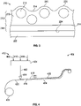
- Fig. 1 is a schematic diagram showing what is believed to be the mechanism for undesirable sparkle induced by a conventional AG film on an optical display.
- light emitting article 10 e.g., an electronic display
- anti-glare film 20 comprising film 22 with ant-glare surface 24 has been adhered to face 19 with adhesive 26.
- film 20 serves to reduce the glare which would otherwise be generated by face 19, it does not transmit light rays 16a, 16b, 16c, et. seq. uniformly; instead emitting rays 28a, 28c relatively directly from rays 16a, 16c, respectively, while other rays such as rays 28b are emitted at substantially off axis orientation from display-emitted rays 16b.
- rays 28a, 28c will be perceived as relatively bright portions of the image while rays 28b will be perceived as relatively dark.
- the impact will vary according to viewing angle, over small variations in perspective. The impact of such variation is perceived as sparkle.
- sparkle may be merely a minor, aesthetic distraction. When more pronounced, however, it degrades resultant image quality, interfering with performance and utility of the optical device.
- sparkle Although the causes of sparkle are not entirely understood, observation reveals that the magnitude of sparkle may depend on such parameters as the surface texture of the subject coating, the distance between the subject film and underling components of the optical device (e.g., the pixels of a display), and the size of the display pixels.
- a problematic trend is that sparkle tends to increases as pixel size of an underlying display decreases. Thus displays in which display resolution is increased by reducing the size of constituent pixels tend to exhibit problematic sparkle.
- the present invention provides novel matte coats that provide a surprising combination of light transmissiveness, low sparkle, low grain (i.e., visible and therefore undesirable coating attributes and features), and high uniformity. If desired, coats of the invention may made so as to exhibit high hardness in conjunction with these characteristics. Aspects of the invention include such matte coats, optical assemblies comprising such matte coats, and methods of making such matte coats.
- Matte coats of the invention have a first major surface and are characterized by a surprising combination of properties.
- matte coats of the invention comprise, and may consist essentially of, a first layer defining the first major face of the matte coat.
- the first layer comprises, and may consist essentially of, a polymeric matrix and a plurality of forming bodies entrained therein.
- the forming bodies have an index of refraction ( n b ) and a select average major dimension.
- the polymeric matrix of the first layer has an index of refraction ( n m ), and a first major surface and a second major surface. In the surface zone at the first major surface there is a plurality of protuberances corresponding to forming bodies entrained within the first layer.
- n b and n m are relatively close (e.g., typically within about 0.1), preferably identical, to one another.
- matte coats of the invention can provide a desirable combination of optical properties.
- Matte coats of the invention are novel in that they comprise forming bodies entrained in a polymer matrix; distinctive features of the invention including the presence of protrusions, and the relative Z-axis position of the plurality of forming bodies.
- an optical assembly of the invention comprises a matte coat of the invention optically coupled to the light emitting surface of a light emitting article.
- the entrained, high relative Z-axis position of forming bodies in the surface zone of coats of the invention is achieved using a novel method which has been found to provide surprising results.
- the forming bodies are selected and forming composition is formulated such that when coated, the composition may be cured in a sufficiently short time that a surface zone with protuberances as described herein is formed.
- the terminal velocity increases as R 2 and thus varies greatly with particle size. If the particle is falling in the viscous fluid under its own weight, then a terminal velocity, or settling velocity, is reached when this frictional force combined with the buoyant force exactly balances the gravitational force.
- a method of the invention comprises method for making a low sparkle matte coat comprising the steps of:
- Matte coats of the invention having the surprising combination of useful properties described above, can be made at low cost.
- the method of the invention is capable of robust, high speed manufacturing, making it well suited for industrial application.
- the term "clarity" is used to mean the ability of a specimen to transmit the fine details of an object or image viewed through it. It is negatively impacted by absorption and by scattering. A quantitative value for clarity can be determined by designating an acceptable (small) spreading angle for transmitted light; then, the clarity is the percentage of all transmitted light which is transmitted within that spreading angle.
- haze is used to mean the percentage of transmitted light which in passing through the specimen deviates from the incident beam, by more than a specified angle, due to forward scattering. Haze can be broken down into two components; one component being the “bulk haze” (sometimes also referred to as the “internal haze”), and the other being the “surface haze”.
- bulk haze is used to mean the haze that results from conditions in the bulk (i.e., the interior) of the specimen, such as the presence of impurities, voids, bubbles, particles, inclusions, regions of differing refractive index, or other optical inhomogeneities.
- values for bulk haze and surface haze can be determined by first obtaining a value for the total haze by an appropriate optical test, then covering the surface with a smooth coating of an index-matching material (often a fluid), testing again to obtain the value for the bulk haze, and then determining the surface haze as the difference between the total haze and bulk haze values.
- an index-matching material often a fluid
- light transmissive is used to mean allowing the transmission of a significant portion of incident light. All incident light must be either reflected, absorbed, or transmitted by a specimen, so absorption, specular reflection, and back-scattering reduce transmission, but forward-scattering does not.
- polymer will be understood to include polymers, copolymers (e.g., polymers formed using two or more different monomers), oligomers and combinations thereof, as well as polymers, oligomers, or copolymers that can be formed in a miscible blend by, for example, coextrusion or reaction, including transesterification. Both block and random copolymers are included, unless indicated otherwise.
- sparkle is used to mean a phenomenon relating to an optical display wherein the displayed image appears to be covered by small highlights that scintillate with relative movement of the display and observer.
- surface haze is used to mean a phenomenon relating to an optical display wherein a displayed image appears to be covered by small colored highlights that scintillate with relative movement of the display and observer.
- Z-axis is used to refer to position relative to the first major face of the matte coat along an axis extending perpendicularly from the first major face toward the rear of the matte coat.
- the Z-axis, "X-axis”, and “Y-axis” are mutually perpendicular.
- the X-axis and Y-axis are defined by the length and width of the coat and its thickness is defined in the Z-axis.
- Weight percent, percent by weight, % by weight, wt %, and the like are synonyms that refer to the concentration of a substance as the weight of that substance divided by the weight of the composition and multiplied by 100.
- Fig. 2 is a cross sectional view of a portion of an illustrative embodiment of a matte coat of the invention.
- Matte coat 110 comprises first layer 112 comprising polymeric matrix 113 having first major surface 114 and second major surface 116. Matte coat 110 comprises a plurality of forming bodies 118 entrained in polymeric matrix 113. First major surface 114 has a plurality of protuberances 120 corresponding to forming bodies 118.
- matte coat 110 further comprises optional adhesive layer 122 on second major surface 116 (i.e., the back face of polymeric matrix 112).
- Fig. 3 is a cross sectional view of a portion of another illustrative embodiment of a matte coat of the invention.
- Matte coat 210 comprises first layer 212 and second layer 215.
- First layer 212 comprises polymeric matrix 213 having first major surface 214 and second major surface 216.
- Second layer 215 is on second major surface 216 of polymeric matrix 212.
- Matte coat 210 comprises a plurality of forming bodies 218 entrained in first layer 213.
- First major surface 214 has a plurality of protuberances 220 corresponding to forming bodies 218.
- matte coat 210 further comprises adhesive layer 222 on second major face 224 of second layer 215.
- matte coats with three or more layers may be formed in accordance with the invention.
- matte coats of the invention will have a sparkle rating of less than 5.0, in some instances less than 3.
- a sparkle rating of 3 is generally considered to be about the limit of what can be perceived by unaided human eye.
- the curable components are selected to yield a polymeric matrix having an index of refraction that is relatively similar to that of the forming bodies used so as to minimize bulk haze and other effects upon light being transmitted through the matte coat.
- the difference between the index of refraction ( n m ) of the polymeric matrix and the an index of refraction ( n b ) of the forming bodies is about 1.0 or less, preferably about 0.05 or less, and most preferably about 0.03 or less.
- index of refraction n b is different from the index of refraction n m the matrix layer will tend to exhibit bulk haze which may interfere with viewing images, etc. which are viewed through the matte film.
- Matte coats of the invention are distinguished by the presence of a surface zone having a plurality of protuberances and a plurality of corresponding forming bodies which are entrained in the layer.
- the surface zone is the portion of the first layer at the first major face thereof wherein a plurality of forming bodies are arranged in proximity to the first major face with a skin of polymeric material thereover to define protuberances.
- the skin is typically preferably from about 0.4 to about 0.8 microns thick.
- the thickness of the first layer is at least 0.7 microns larger than the average major dimension of the forming bodies.
- the forming bodies are preferably spaced apart so as to have polymeric matrix between adjacent polymeric bodies, and in some instances preferably substantially in a monolayer.
- Matte coats of the invention provide a surprising and heretofore unattained combination of properties.
- the front face (i.e., first major surface of the first layer) of matte coats of the invention have a surface haze of about 40% or less, and in some embodiments about 25% or less.
- the benefits of the advantageous sparkle reduction provided by the invention tend to be more prominent at lower haze ratings.
- matte coats of the invention have a bulk haze of about 10 percent or less.
- matte coats of the invention have a clarity of less than about 95, preferably less than 90, and most preferably less than 80.
- matte coats of the invention may be made in desirable hardness. If desired, they may be made having a hardness of at least about H according to ASTM D3363-00.
- matte coats of the invention have a thickness of about 10 microns or less. As will be understood, embodiments of matte coats with greater thicknesses may be made in accordance with the invention.
- matte coats with a first major face with a select topography which imparts desired optical effects can be formed through curing of select combination of materials as described herein.
- the invention provides a surprising combination of performance and ease.
- Fig. 4 illustrates an illustrative embodiment 400 of the method of the invention, the method comprising the steps of:
- the first layer may be wound into roll form for storage, transport, application to desired surfaces, application of adhesive to its back face, etc.
- the level of the coating tends to recede, sinking down between forming bodies proximate the first surface such that the resulting first major face is textured with a plurality of protuberances.
- the forming bodies Due to the relatively high viscosity of the curing composition, the forming bodies are not exposed and substantially all of them are covered by at least a protuberance of lamina or skin of cured polymeric matrix material.
- the resultant protuberance (made up of at least polymeric matrix material of the skin, and in some instances the portions of entrained forming bodies which lie above the base line of the surrounding portions of the first major surface as well as overlying skin).
- compositions comprising forming bodies and curable materials of relatively high density, in compositions of relatively high viscosity, can be used to form layers with textured surfaces as described herein.
- the film-forming curable mixture has a viscosity and density
- the forming bodies have a density and an average major dimension such that after being coated, the curable components may be dried and reacted to yield the desired polymeric matrix containing an effective number of forming bodies which have sunk to only a limited extent such that they are located proximate to the first major surface of the subject layer with a skin of the polymeric matrix forming an upwardly swelled portion or protuberance.
- Fig. 5a shows a deposit 502 of coating composition on surface 504.
- Deposit 502 comprises forming bodies 506 dispersed in mass 508 of the liquid coating composition. Some of forming bodies 506 are positioned closer to first surface 510. As the curable components are cured (i.e., solvent is removed and components react), the level of first surface 510 will tend to recede, yielding the structure shown in Fig. 5b , wherein matte coating 520 has a plurality of protuberances 522 corresponding to entrained forming bodies 506. Protuberances 522 are separated by land portions 524 of first surface 510. Each protuberance is a laminae 526 of polymeric matrix covering an entrained forming body 506.
- a portion 528 of an entrained forming body 506 though covered by skin or lamina 526 extends above the level of the land portions 524 (shown as dotted line 524a).
- the entrained forming body 506 does not extend above level 524a (e.g., such as forming body 506a) and protuberance 530 is made up entirely of the lamina or skin.
- the protuberances provide desired matte properties as described herein.
- Other forming bodies 506b, which are located deeper within the first layer do not have corresponding protuberances.
- the film-forming composition has a viscosity of from about 75 to about 3,000 cps, sometimes preferably from about 150 to about 1,200 cps, when deposited into coating form. In instances where longer cure times are involved (e.g., through selection of such curable components, use of lower intensity actinic radiation, slower processing speeds, etc.), it will typically be preferred to use higher viscosity compositions.
- the film-forming composition has a density of about 0.95 or more when deposited into coating form. In instances where longer cure times are involved (e.g., through selection of such curable components, use of lower intensity actinic radiation, slower processing speeds, etc.), it will typically be preferred to use higher density compositions.
- the forming bodies have a density of from about 1.1 to about 2.5. In instances where longer cure times are involved (e.g., through selection of such curable components, use of lower intensity actinic radiation, slower processing speeds, etc.), it will typically be preferred to use forming bodies having lower density.
- the resultant layers are well suited for use as low sparkle matte coats, providing heretofore unattainable combinations of properties.
- the forming composition may be deposited in desired fashion (e.g., on a temporary support such as a release liner, or on a substrate member to which it is permanently bonded) via many known coating techniques (e.g., slot and die, roll coating, etc.).
- coatings of the invention can be made using slide coating.
- slide coating is carried out utilizing high density, high viscosity fluids to prevent forming body settling and agglomeration.
- slide coating typically tends to avoiding significant agglomeration of forming bodies and formation of bare spots (sometimes called "lakes") as are encountered with conventional coating techniques used at high forming body loading.
- the film-forming curable mixture comprises one or more reactive polymeric materials and one or more solvents.
- the mixture may comprise one or more monomers which are reactive with at least one of the reactive polymeric materials.
- reactive polymeric materials include thermosetting or thermoplastic polymers such as polycarbonates, poly(meth)acrylates (e.g., polymethyl methacrylate (“PMMA”), polyolefins (e.g., polypropylene (“PP”)), polyurethanes, polyesters (e.g., polyethylene terephthalate (PET)), polyamides, polyimides, phenolic resins, cellulose diacetate, cellulose triacetate, polystyrene, styrene-acrylonitrile copolymers, epoxies, and the like.
- preferred polymers include cellulose acetate butyrate and ethoxylated trimethylolpropane triacrylate.
- Monomers chosen must be compatible with the polymers in the chosen solvent(s), such as acrylates.
- Suitable solvents can be selected by those skilled in the art.
- An illustrative example is propylene glycol methylether (e.g., DOWANOL ® PM) which is an effective solvent for many suitable reactive polymers and monomers that is also relatively dense.
- An aspect of the present invention is that relatively high density of the coating fluid is used to achieve positioning of the forming bodies at the surface zone of the resultant first layer as desired.
- nanoparticles such as silica may be incorporated in the film forming composition to increase its effective density or viscosity so as slow the tendency of the forming bodies to sink away from the first major surface before curing is complete.
- An advantage of such additives is that they can also impart increased hardness to the resultant matte coat.
- additives may be added to speed curing (e.g., photoinitiator in the case of UV curable components).
- the forming bodies will be present at weight loading of from about 0.5 to about 60 wt % solids in the forming composition. If the weight loading is too high, forming bodies may tend to agglomerate, thereby creating defects in the resultant matte coating such as physically disrupted portions, exposed and loose forming bodies, and intervening bare spots or "lakes" in which desired glare reduction without sparkle is not achieved. Also, at high weight loading, the forming bodies may tend to fail to become entrained within the polymeric matrix, resulting a matte coating with exposed forming bodies protruding from the first major face of the first layer.
- the forming bodies function to impart desired texture or protuberances to the front face of the matte coat (i.e., the first major face of the first layer of the polymeric matrix) and also optically couple with the polymeric matrix such that light can be transmitted through the matte coat without undesired effects.
- the forming bodies are rounded in shape, and in some instances substantially spherical. Such shapes are not required, though are sometimes preferred as being easier to use and tending to yield more uniform results.
- the forming particles are characterized by size (i.e., average major dimension (which in the case of a sphere is its diameter)).
- forming particles used in a matte film will be varied dimension and shape. In other instances, the dimension, shape, or both will be substantially uniform.
- the difference in density between the forming bodies and the liquid resin composition is chosen to be less than about 0.25.
- the forming bodies may tend to sink more rapidly than desired so as to reduce the degree for formation of protuberances during curing.
- the forming bodies and polymeric matrix be of the same color (i.e., be chromatically similar) at least with respect to the wavelength band(s) of light in which the matte coat is intended to be used, and also to have similar index of refraction as the polymeric matrix as described herein.
- the average major dimension of the forming bodies is from about 0.8 to about 10 microns, with forming bodies from about 2 to about 5 microns typically being preferred, and about 3 microns typically being more preferred.
- the resultant matte film may be subject to one or both of undesirable sparkle and undesirable graininess.
- the threshold for forming bodies which can be detected by the unaided human eye is about 3 microns.
- matte coats of the invention can be formed on temporary supports from which they are separated and then bonded to a desired surface (e.g., by lamination or bonding with adhesive).
- an adhesive optionally covered with a protective release liner, will be provided on the back face of the matte coat to bond it to desired surface.
- a protective release liner many suitable adhesives for optical applications are known; those with ordinary skill in the art will be readily able to select suitable adhesive for a desired application.
- matte coats of the invention may be used to beneficial effect on a variety of light emitting surfaces, combinations which are referred to herein as optical assemblies.
- Illustrative examples include privacy films, window film, phones, tablets, notebook computers, monitors, televisions, signage displays, etc.
- Code Component A EB 8301R aliphatic urethane hexaacrylate, from Cytec B SR9035: ethoxylated, trimethylolpropane triacrylate, from Sartomer C CAB-381-20: cellulose acetate butyrate, from Eastman Kodak D ESACURE TM
- E TEGO ® Glide 100 polyether-modified polysiloxane, from Evonik Industries
- Dowanol ® PM propylene glycol methylether, from Dow G MX 150: 1.5 micron PMMA forming bodies, from Soken Chemical and Engineering Co.
- H MX 300 3 micron PMMA forming bodies, from Soken Chemical and Engineering Co.
- I MX 500 5 micron PMMA forming bodies, from Soken Chemical and Engineering Co.
- J MBX-8 8 micron PMMA forming bodies, from Sekisui Plastics Co.
- K 20 nm silica solution (as described in US2013/0302594 A1 , page 7 section 0058)
- Sparkle level as measured with a SMS-1000 correlates well with visual evaluations using an analytic hierarchy process (AHP) based on paired comparisons done by lab personnel familiar with identifying sparkle.
- the sparkle rating or number itself, is a ratio of the standard deviation divided by the mean of the luminance in a user-defined region of interest in the image. For ease of reporting, the measured value is multiplied by 100 to arrive at a whole number scale (e.g., the baseline measurement of a gloss display with no sparkle would read 0.030, but is reported as 3.0).
- the minimum level is display dependent and is typically between 2 and 4.
- a sparkle level of less than 5 is deemed acceptable, from 5 to 6 is deemed marginal, and higher than 6 is deemed not acceptable.
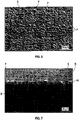
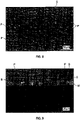
- Figs. 6-11 are scanning electron microscope images of select matte coats from the Examples as follows: Fig. Example Description of View (Magnification) 6 1 Plan view of first major surface from 25° tilt (250X) 7 1 Cross section of first layer (1,000X) 8 2 Plan view of first major surface from 25° tilt (250X) 9 2 Cross section of first layer (1,000X) 10 3 Plan view of first major surface from 25° tilt (250X) 11 3 Cross section of first layer (1,000X)
- first major surfaces S and protuberances P are visible (each with an entrained forming body underneath within the polymeric matrix).
- cross-sectional views 7 and 9 forming bodies B and polymeric matrix M were visible.
- cross-sectional view 11 polymeric matrix M was visible but no forming body happened to be in this view.
Landscapes
- Physics & Mathematics (AREA)
- General Physics & Mathematics (AREA)
- Optics & Photonics (AREA)
- Chemical & Material Sciences (AREA)
- Dispersion Chemistry (AREA)
- Application Of Or Painting With Fluid Materials (AREA)
- Laminated Bodies (AREA)
- Optical Elements Other Than Lenses (AREA)
- Paints Or Removers (AREA)
Claims (14)
- Revêtement mat (110) ayant une première surface principale, le revêtement mat comprenant une première couche (112) définissant la première surface principale (114) du revêtement mat, la première couche comprenant une matrice polymère (113) et une pluralité de corps de formation (118) entraînés dans celle-ci, dans lequel :les corps de formation ont un indice de réfraction (n b) et une dimension principale moyenne,la première couche a un indice de réfraction (n m ), dans lequel la première surface principale a une pluralité de protubérances (120) correspondant aux corps de formation entraînés au sein de la première couche ;n b est à plus ou moins environ 0,1 de n m ; etla différence de masse volumique entre les corps de formation et une résine polymère liquide qui forme la matrice polymère est inférieure à environ 0,25 kg/m3.
- Revêtement mat selon la revendication 1 dans lequel l'épaisseur de la première couche vaut environ 1,5 fois la dimension principale moyenne des corps de formation.
- Revêtement mat selon la revendication 1 dans lequel les corps de formation ont un indice de réfraction (n b) allant d'environ 1,35 à environ 2,2.
- Revêtement mat selon la revendication 1 comprenant en outre une deuxième couche (210) sur une deuxième surface principale de la première couche, la deuxième couche comprenant un matériau polymère durci, dans lequel la première couche et la deuxième couche ont été durcies in situ.
- Revêtement mat selon la revendication 1 dans lequel n b est à plus ou moins environ 0,05 de n m .
- Revêtement mat selon la revendication 1 dans lequel la matrice polymère et les corps de formation sont chromatiquement similaires.
- Ensemble optique comprenant un revêtement mat selon la revendication 1 sur une surface d'émission de lumière.
- Procédé de fabrication d'un revêtement mat à faible scintillement comprenant les étapes consistant à :préparer une composition de formation comprenant un mélange durcissable filmogène et une pluralité de corps de formation, dans lequel le mélange durcissable filmogène a une viscosité d'au moins environ 75 cP et une masse volumique d'au moins environ 0,95 kg/m3, et les corps de formation ont une masse volumique d'au moins environ 1,1 kg/m3, la différence de masse volumique entre les corps de formation et une résine polymère liquide de la composition de formation qui forme une matrice polymère étant inférieure à environ 0,25 kg/m3, un indice de réfraction (n b), et une dimension principale moyenne ;déposer la composition de formation en un revêtement ayant une surface principale ; puisdurcir le mélange durcissable du revêtement de telle sorte que le mélange durcissable polymérise et se rétracte pour donner la matrice polymère ayant une pluralité de protubérances sur la surface principale de celle-ci correspondant à des corps de formation entraînés au sein de la matrice polymère.
- Procédé selon la revendication 8 dans lequel la composition de formation a une viscosité allant d'environ 75 à environ 3000 cP lorsqu'elle est déposée dans une forme de revêtement.
- Procédé selon la revendication 8 dans lequel la composition de formation a une masse volumique d'environ 0,95 kg/m3 ou plus lorsqu'elle est déposée dans une forme de revêtement.
- Procédé selon la revendication 8 dans lequel les corps de formation ont une masse volumique allant d'environ 1,1 kg/m3 à environ 2,5 kg/m3.
- Procédé selon la revendication 8 dans lequel les corps de formation ont un indice de réfraction (n b) allant d'environ 1,35 à environ 2,2.
- Procédé selon la revendication 8 dans lequel le mélange durcissable filmogène comprend au moins un parmi acétobutyrate de cellulose et triacrylate de triéméthylolpropane éthoxylé.
- Procédé selon la revendication 8 dans lequel la dimension principale moyenne des corps de formation va d'environ 0,8 à environ 10 micromètres.
Applications Claiming Priority (2)
| Application Number | Priority Date | Filing Date | Title |
|---|---|---|---|
| US201562218963P | 2015-09-15 | 2015-09-15 | |
| PCT/US2016/051943 WO2017048957A1 (fr) | 2015-09-15 | 2016-09-15 | Revêtements mats à faible brillance et procédés de fabrication |
Publications (2)
| Publication Number | Publication Date |
|---|---|
| EP3350631A1 EP3350631A1 (fr) | 2018-07-25 |
| EP3350631B1 true EP3350631B1 (fr) | 2022-07-13 |
Family
ID=57083360
Family Applications (1)
| Application Number | Title | Priority Date | Filing Date |
|---|---|---|---|
| EP16777834.9A Active EP3350631B1 (fr) | 2015-09-15 | 2016-09-15 | Revêtements mats à faible brillance et procédés de fabrication |
Country Status (7)
| Country | Link |
|---|---|
| US (2) | US10732331B2 (fr) |
| EP (1) | EP3350631B1 (fr) |
| JP (1) | JP7402609B2 (fr) |
| KR (1) | KR20180053678A (fr) |
| CN (1) | CN108027461B (fr) |
| TW (1) | TW201727276A (fr) |
| WO (1) | WO2017048957A1 (fr) |
Families Citing this family (6)
| Publication number | Priority date | Publication date | Assignee | Title |
|---|---|---|---|---|
| KR102265369B1 (ko) * | 2017-06-06 | 2021-06-16 | 케이와 인코포레이티드 | 상부용 광 확산 시트 및 그를 구비한 백라이트 유닛 |
| JP6721794B2 (ja) * | 2017-08-04 | 2020-07-15 | 株式会社ダイセル | 防眩フィルム |
| KR102300811B1 (ko) | 2017-08-04 | 2021-09-13 | 주식회사 다이셀 | 방현 필름 |
| CN111954831B (zh) * | 2018-03-07 | 2024-02-02 | 凸版印刷株式会社 | 光学膜、光学阻隔膜以及背光单元 |
| TWI774005B (zh) * | 2020-06-15 | 2022-08-11 | 明基材料股份有限公司 | 防眩膜及具有此防眩膜之偏光板 |
| TWI789017B (zh) * | 2021-09-17 | 2023-01-01 | 明基材料股份有限公司 | 高霧度防眩膜以及高霧度防眩抗反射膜 |
Family Cites Families (46)
| Publication number | Priority date | Publication date | Assignee | Title |
|---|---|---|---|---|
| US5104929A (en) | 1988-04-11 | 1992-04-14 | Minnesota Mining And Manufacturing Company | Abrasion resistant coatings comprising silicon dioxide dispersions |
| JP4034365B2 (ja) | 1995-03-09 | 2008-01-16 | 大日本印刷株式会社 | 超微粒子含有反射防止フィルム、偏光板及び液晶表示装置 |
| US5919555A (en) | 1996-11-06 | 1999-07-06 | Fuji Photo Film Co., Ltd. | Anti-reflection film and display device having the same |
| US5780109A (en) | 1997-01-21 | 1998-07-14 | Minnesota Mining And Manufacturing Company | Die edge cleaning system |
| JP2967474B2 (ja) | 1997-03-27 | 1999-10-25 | 株式会社巴川製紙所 | 防眩材料及びそれを使用した偏光フィルム |
| US6576296B1 (en) | 1998-03-10 | 2003-06-10 | 3M Innovative Properties Company | Web coating method and apparatus for continuous coating over splices |
| US6376060B1 (en) | 1998-09-25 | 2002-04-23 | Dai Nippon Printing Co., Ltd. | Hardcoat film |
| JP3515401B2 (ja) | 1998-12-18 | 2004-04-05 | 大日本印刷株式会社 | 防眩フィルム、偏光板及び透過型表示装置 |
| KR100673796B1 (ko) | 1999-09-09 | 2007-01-24 | 키모토 컴파니 리미티드 | 투명 하드코트 필름 |
| KR20040048931A (ko) * | 2001-10-04 | 2004-06-10 | 후지 샤신 필름 가부시기가이샤 | 투과형 액정 표시장치 |
| JP4080756B2 (ja) | 2002-02-01 | 2008-04-23 | 富士フイルム株式会社 | 反射防止膜とその製造方法ならびに画像表示装置 |
| US7354163B2 (en) * | 2002-02-08 | 2008-04-08 | Dai Nippon Printing Co., Ltd. | Antiglare film and image display apparatus |
| WO2003071316A1 (fr) * | 2002-02-25 | 2003-08-28 | Fuji Photo Film Co., Ltd. | Film anti-eblouissant et anti-reflet, plaque de polarisation et dispositif d'affichage dans lesquels ledit film est utilise |
| TW557363B (en) | 2002-10-15 | 2003-10-11 | Optimax Tech Corp | Anti-glare film |
| US7074463B2 (en) | 2003-09-12 | 2006-07-11 | 3M Innovative Properties Company | Durable optical element |
| JP4074847B2 (ja) * | 2003-09-30 | 2008-04-16 | 恵和株式会社 | 光学シート及びこれを用いたバックライトユニット |
| US20050100690A1 (en) | 2003-11-06 | 2005-05-12 | Optical Coating Laboratory Inc., A Jds Uniphase Company | Dyed polymer coating for display panel |
| US20060153979A1 (en) * | 2004-11-30 | 2006-07-13 | Fuji Photo Film Co., Ltd. | Anti-glare and anti-reflection film, polarizing plate using the anti-glare and anti-reflection film, and liquid crystal display device using the polarizing plate |
| WO2006090879A1 (fr) * | 2005-02-22 | 2006-08-31 | Fujifilm Corporation | Film, son procede de fabrication, plaque de polarisation utilisant ledit film, cristal liquide et dispositif d’affichage utilisant la plaque de polarisation |
| JP2007065160A (ja) * | 2005-08-30 | 2007-03-15 | Keiwa Inc | 光学シート用基材フィルム、光学シート及びバックライトユニット |
| US7505104B2 (en) * | 2005-09-16 | 2009-03-17 | Fujifilm Corporation | Antiglare antireflective film, polarizing plate and liquid crystal display |
| US20070177271A1 (en) * | 2006-02-02 | 2007-08-02 | Fujifilm Corporation | Antireflection film, polarizing plate and image display |
| JP5011877B2 (ja) * | 2006-08-04 | 2012-08-29 | 凸版印刷株式会社 | 防眩性光拡散部材及び防眩性光拡散部材を有するディスプレイ |
| JP2008040063A (ja) | 2006-08-04 | 2008-02-21 | Toppan Printing Co Ltd | 防眩性光拡散部材 |
| JP2008145499A (ja) * | 2006-12-06 | 2008-06-26 | Toppan Printing Co Ltd | 防眩性光拡散部材 |
| JP2008191310A (ja) * | 2007-02-02 | 2008-08-21 | Toppan Printing Co Ltd | 防眩フィルム |
| JP2008216430A (ja) * | 2007-03-01 | 2008-09-18 | Toppan Printing Co Ltd | 防眩フィルム |
| JP2008216539A (ja) | 2007-03-02 | 2008-09-18 | Toppan Printing Co Ltd | 防眩フィルム |
| JP2008216538A (ja) | 2007-03-02 | 2008-09-18 | Toppan Printing Co Ltd | 防眩フィルム |
| US7902266B2 (en) | 2007-11-30 | 2011-03-08 | Taiflex Scientific Co., Ltd. | Composition of anti-glare coating |
| JP2009244509A (ja) * | 2008-03-31 | 2009-10-22 | Mitsubishi Rayon Co Ltd | 反射シート |
| CN101579672A (zh) | 2008-05-16 | 2009-11-18 | 3M创新有限公司 | 用于提高亲水性/透射率的二氧化硅涂层 |
| JP5200918B2 (ja) | 2008-12-25 | 2013-06-05 | 凸版印刷株式会社 | 防眩フィルム |
| CN102460225B (zh) | 2009-06-02 | 2014-10-22 | 3M创新有限公司 | 包括微结构化表面的防眩膜 |
| JP2010280203A (ja) | 2009-06-08 | 2010-12-16 | Polymatech Co Ltd | 加飾シートおよび加飾シートの製造方法並びに加飾成形体 |
| KR101842728B1 (ko) | 2010-05-07 | 2018-03-27 | 쓰리엠 이노베이티브 프로퍼티즈 컴파니 | 미세구조화 표면을 포함하는 반사방지 필름 |
| CN103052898B (zh) | 2010-08-05 | 2016-01-20 | 3M创新有限公司 | 包括哑光表面层的多层膜和制品 |
| US20130236697A1 (en) | 2010-12-01 | 2013-09-12 | 3M Innovative Properties Company | Microstructured articles comprising nanostructures and method |
| EP2670796B1 (fr) | 2011-02-03 | 2018-05-16 | 3M Innovative Properties Company | Revêtement dur |
| JP6046367B2 (ja) * | 2011-04-12 | 2016-12-14 | 恵和株式会社 | 光学ユニット、バックライトユニット及び液晶表示装置 |
| US9573842B2 (en) | 2011-05-27 | 2017-02-21 | Corning Incorporated | Transparent glass substrate having antiglare surface |
| WO2013096324A1 (fr) | 2011-12-21 | 2013-06-27 | 3M Innovative Properties Company | Empilement de films optiques |
| US20150017386A1 (en) * | 2012-02-01 | 2015-01-15 | 3M Innovative Properties Company | Nanostructured materials and methods of making the same |
| WO2013127054A1 (fr) | 2012-02-27 | 2013-09-06 | 3M Innovative Properties Company | Compositions basiques incluant des nanoparticules d'oxyde inorganique et une base organique, substrats enduits, articles, et procédés |
| SG11201608892PA (en) | 2014-04-25 | 2016-11-29 | 3M Innovative Properties Co | Textured coating for optical products |
| KR102301486B1 (ko) * | 2014-12-02 | 2021-09-13 | 삼성디스플레이 주식회사 | 편광 부재 및 이를 포함하는 표시 장치 |
-
2016
- 2016-09-15 EP EP16777834.9A patent/EP3350631B1/fr active Active
- 2016-09-15 CN CN201680053692.3A patent/CN108027461B/zh active Active
- 2016-09-15 KR KR1020187009306A patent/KR20180053678A/ko not_active Application Discontinuation
- 2016-09-15 US US15/760,180 patent/US10732331B2/en active Active
- 2016-09-15 JP JP2018513506A patent/JP7402609B2/ja active Active
- 2016-09-15 WO PCT/US2016/051943 patent/WO2017048957A1/fr active Application Filing
- 2016-09-19 TW TW105130234A patent/TW201727276A/zh unknown
-
2020
- 2020-06-25 US US16/911,483 patent/US10845509B2/en active Active
Also Published As
| Publication number | Publication date |
|---|---|
| TW201727276A (zh) | 2017-08-01 |
| CN108027461B (zh) | 2022-07-22 |
| WO2017048957A9 (fr) | 2017-05-18 |
| JP7402609B2 (ja) | 2023-12-21 |
| WO2017048957A1 (fr) | 2017-03-23 |
| CN108027461A (zh) | 2018-05-11 |
| US10732331B2 (en) | 2020-08-04 |
| US20180252848A1 (en) | 2018-09-06 |
| KR20180053678A (ko) | 2018-05-23 |
| JP2018533050A (ja) | 2018-11-08 |
| US10845509B2 (en) | 2020-11-24 |
| EP3350631A1 (fr) | 2018-07-25 |
| US20200326458A1 (en) | 2020-10-15 |
Similar Documents
| Publication | Publication Date | Title |
|---|---|---|
| US10845509B2 (en) | Low sparkle matte coats and methods of making | |
| EP2144094A1 (fr) | Film antireflet, procédé de production du film et dispositif d'affichage l'utilisant | |
| KR101441829B1 (ko) | 하드 코트층용 경화성 수지 조성물, 하드 코트 필름의 제조 방법, 하드 코트 필름, 편광판 및 디스플레이 패널 | |
| KR102055017B1 (ko) | 방현성 필름의 제조 방법, 방현성 필름, 편광판 및 화상 표시 장치 | |
| KR101920523B1 (ko) | 방현성 필름, 편광판 및 화상 표시 장치 | |
| TWI332088B (en) | Anti-glare film | |
| KR101108907B1 (ko) | 방현 필름 | |
| CN101679798A (zh) | 用于防眩光膜的组合物及使用其制备的防眩光膜 | |
| KR20120032460A (ko) | 방현 하드코트 필름 | |
| JP2009204728A (ja) | 防眩性積層体及びそれを備えるディスプレイ | |
| JP2016045448A (ja) | 光硬化性樹脂組成物、該組成物から形成される硬化被膜および防眩フィルム、画像表示装置、並びに硬化被膜および防眩フィルムの製造方法 | |
| KR102027593B1 (ko) | 화상 표시 장치, 방현성 필름 및 방현성 필름의 제조 방법 | |
| KR102280262B1 (ko) | 반사 방지 필름, 편광판 및 디스플레이 장치 | |
| JP2018055056A (ja) | 防眩性反射防止ハードコートフィルム、画像表示装置、防眩性反射防止ハードコートフィルムの製造方法 | |
| JP2017167560A (ja) | 防眩性フィルムの製造方法、防眩性フィルム、偏光板および画像表示装置 | |
| KR20170129146A (ko) | 반사 방지 필름, 해당 반사 방지 필름을 사용한 표시 장치, 및 반사 방지 필름의 선택 방법 | |
| CN112646501A (zh) | 一种高透过率防眩防爆保护膜及其制备方法 | |
| KR101285465B1 (ko) | 눈부심 방지 필름 형성용 조성물, 및 이를 이용하여 제조된 눈부심 방지 필름 | |
| WO2020100958A1 (fr) | Film antireflet, son procédé de fabrication, élément optique et dispositif d'affichage d'image | |
| WO2019221573A1 (fr) | Film antireflet, plaque polarisante et appareil d'affichage | |
| KR20160143677A (ko) | 방현 필름 | |
| JP2020122926A (ja) | 防眩性反射防止ハードコートフィルム、画像表示装置、および防眩性反射防止ハードコートフィルムの製造方法 | |
| EP3923039A1 (fr) | Film antireflet, plaque polarisante et appareil d'affichage |
Legal Events
| Date | Code | Title | Description |
|---|---|---|---|
| STAA | Information on the status of an ep patent application or granted ep patent |
Free format text: STATUS: THE INTERNATIONAL PUBLICATION HAS BEEN MADE |
|
| PUAI | Public reference made under article 153(3) epc to a published international application that has entered the european phase |
Free format text: ORIGINAL CODE: 0009012 |
|
| STAA | Information on the status of an ep patent application or granted ep patent |
Free format text: STATUS: REQUEST FOR EXAMINATION WAS MADE |
|
| 17P | Request for examination filed |
Effective date: 20180322 |
|
| AK | Designated contracting states |
Kind code of ref document: A1 Designated state(s): AL AT BE BG CH CY CZ DE DK EE ES FI FR GB GR HR HU IE IS IT LI LT LU LV MC MK MT NL NO PL PT RO RS SE SI SK SM TR |
|
| AX | Request for extension of the european patent |
Extension state: BA ME |
|
| DAV | Request for validation of the european patent (deleted) | ||
| DAX | Request for extension of the european patent (deleted) | ||
| GRAP | Despatch of communication of intention to grant a patent |
Free format text: ORIGINAL CODE: EPIDOSNIGR1 |
|
| STAA | Information on the status of an ep patent application or granted ep patent |
Free format text: STATUS: GRANT OF PATENT IS INTENDED |
|
| INTG | Intention to grant announced |
Effective date: 20220127 |
|
| GRAS | Grant fee paid |
Free format text: ORIGINAL CODE: EPIDOSNIGR3 |
|
| GRAA | (expected) grant |
Free format text: ORIGINAL CODE: 0009210 |
|
| STAA | Information on the status of an ep patent application or granted ep patent |
Free format text: STATUS: THE PATENT HAS BEEN GRANTED |
|
| AK | Designated contracting states |
Kind code of ref document: B1 Designated state(s): AL AT BE BG CH CY CZ DE DK EE ES FI FR GB GR HR HU IE IS IT LI LT LU LV MC MK MT NL NO PL PT RO RS SE SI SK SM TR |
|
| REG | Reference to a national code |
Ref country code: CH Ref legal event code: EP |
|
| REG | Reference to a national code |
Ref country code: DE Ref legal event code: R096 Ref document number: 602016073508 Country of ref document: DE |
|
| REG | Reference to a national code |
Ref country code: IE Ref legal event code: FG4D |
|
| REG | Reference to a national code |
Ref country code: AT Ref legal event code: REF Ref document number: 1504560 Country of ref document: AT Kind code of ref document: T Effective date: 20220815 |
|
| REG | Reference to a national code |
Ref country code: LT Ref legal event code: MG9D |
|
| REG | Reference to a national code |
Ref country code: NL Ref legal event code: MP Effective date: 20220713 |
|
| PG25 | Lapsed in a contracting state [announced via postgrant information from national office to epo] |
Ref country code: SE Free format text: LAPSE BECAUSE OF FAILURE TO SUBMIT A TRANSLATION OF THE DESCRIPTION OR TO PAY THE FEE WITHIN THE PRESCRIBED TIME-LIMIT Effective date: 20220713 Ref country code: RS Free format text: LAPSE BECAUSE OF FAILURE TO SUBMIT A TRANSLATION OF THE DESCRIPTION OR TO PAY THE FEE WITHIN THE PRESCRIBED TIME-LIMIT Effective date: 20220713 Ref country code: PT Free format text: LAPSE BECAUSE OF FAILURE TO SUBMIT A TRANSLATION OF THE DESCRIPTION OR TO PAY THE FEE WITHIN THE PRESCRIBED TIME-LIMIT Effective date: 20221114 Ref country code: NO Free format text: LAPSE BECAUSE OF FAILURE TO SUBMIT A TRANSLATION OF THE DESCRIPTION OR TO PAY THE FEE WITHIN THE PRESCRIBED TIME-LIMIT Effective date: 20221013 Ref country code: NL Free format text: LAPSE BECAUSE OF FAILURE TO SUBMIT A TRANSLATION OF THE DESCRIPTION OR TO PAY THE FEE WITHIN THE PRESCRIBED TIME-LIMIT Effective date: 20220713 Ref country code: LV Free format text: LAPSE BECAUSE OF FAILURE TO SUBMIT A TRANSLATION OF THE DESCRIPTION OR TO PAY THE FEE WITHIN THE PRESCRIBED TIME-LIMIT Effective date: 20220713 Ref country code: LT Free format text: LAPSE BECAUSE OF FAILURE TO SUBMIT A TRANSLATION OF THE DESCRIPTION OR TO PAY THE FEE WITHIN THE PRESCRIBED TIME-LIMIT Effective date: 20220713 Ref country code: FI Free format text: LAPSE BECAUSE OF FAILURE TO SUBMIT A TRANSLATION OF THE DESCRIPTION OR TO PAY THE FEE WITHIN THE PRESCRIBED TIME-LIMIT Effective date: 20220713 Ref country code: ES Free format text: LAPSE BECAUSE OF FAILURE TO SUBMIT A TRANSLATION OF THE DESCRIPTION OR TO PAY THE FEE WITHIN THE PRESCRIBED TIME-LIMIT Effective date: 20220713 |
|
| REG | Reference to a national code |
Ref country code: AT Ref legal event code: MK05 Ref document number: 1504560 Country of ref document: AT Kind code of ref document: T Effective date: 20220713 |
|
| PG25 | Lapsed in a contracting state [announced via postgrant information from national office to epo] |
Ref country code: PL Free format text: LAPSE BECAUSE OF FAILURE TO SUBMIT A TRANSLATION OF THE DESCRIPTION OR TO PAY THE FEE WITHIN THE PRESCRIBED TIME-LIMIT Effective date: 20220713 Ref country code: IS Free format text: LAPSE BECAUSE OF FAILURE TO SUBMIT A TRANSLATION OF THE DESCRIPTION OR TO PAY THE FEE WITHIN THE PRESCRIBED TIME-LIMIT Effective date: 20221113 Ref country code: HR Free format text: LAPSE BECAUSE OF FAILURE TO SUBMIT A TRANSLATION OF THE DESCRIPTION OR TO PAY THE FEE WITHIN THE PRESCRIBED TIME-LIMIT Effective date: 20220713 Ref country code: GR Free format text: LAPSE BECAUSE OF FAILURE TO SUBMIT A TRANSLATION OF THE DESCRIPTION OR TO PAY THE FEE WITHIN THE PRESCRIBED TIME-LIMIT Effective date: 20221014 |
|
| REG | Reference to a national code |
Ref country code: DE Ref legal event code: R097 Ref document number: 602016073508 Country of ref document: DE |
|
| PG25 | Lapsed in a contracting state [announced via postgrant information from national office to epo] |
Ref country code: SM Free format text: LAPSE BECAUSE OF FAILURE TO SUBMIT A TRANSLATION OF THE DESCRIPTION OR TO PAY THE FEE WITHIN THE PRESCRIBED TIME-LIMIT Effective date: 20220713 Ref country code: RO Free format text: LAPSE BECAUSE OF FAILURE TO SUBMIT A TRANSLATION OF THE DESCRIPTION OR TO PAY THE FEE WITHIN THE PRESCRIBED TIME-LIMIT Effective date: 20220713 Ref country code: MC Free format text: LAPSE BECAUSE OF FAILURE TO SUBMIT A TRANSLATION OF THE DESCRIPTION OR TO PAY THE FEE WITHIN THE PRESCRIBED TIME-LIMIT Effective date: 20220713 Ref country code: DK Free format text: LAPSE BECAUSE OF FAILURE TO SUBMIT A TRANSLATION OF THE DESCRIPTION OR TO PAY THE FEE WITHIN THE PRESCRIBED TIME-LIMIT Effective date: 20220713 Ref country code: CZ Free format text: LAPSE BECAUSE OF FAILURE TO SUBMIT A TRANSLATION OF THE DESCRIPTION OR TO PAY THE FEE WITHIN THE PRESCRIBED TIME-LIMIT Effective date: 20220713 Ref country code: AT Free format text: LAPSE BECAUSE OF FAILURE TO SUBMIT A TRANSLATION OF THE DESCRIPTION OR TO PAY THE FEE WITHIN THE PRESCRIBED TIME-LIMIT Effective date: 20220713 |
|
| REG | Reference to a national code |
Ref country code: CH Ref legal event code: PL |
|
| PLBE | No opposition filed within time limit |
Free format text: ORIGINAL CODE: 0009261 |
|
| STAA | Information on the status of an ep patent application or granted ep patent |
Free format text: STATUS: NO OPPOSITION FILED WITHIN TIME LIMIT |
|
| REG | Reference to a national code |
Ref country code: BE Ref legal event code: MM Effective date: 20220930 |
|
| PG25 | Lapsed in a contracting state [announced via postgrant information from national office to epo] |
Ref country code: SK Free format text: LAPSE BECAUSE OF FAILURE TO SUBMIT A TRANSLATION OF THE DESCRIPTION OR TO PAY THE FEE WITHIN THE PRESCRIBED TIME-LIMIT Effective date: 20220713 Ref country code: EE Free format text: LAPSE BECAUSE OF FAILURE TO SUBMIT A TRANSLATION OF THE DESCRIPTION OR TO PAY THE FEE WITHIN THE PRESCRIBED TIME-LIMIT Effective date: 20220713 |
|
| 26N | No opposition filed |
Effective date: 20230414 |
|
| GBPC | Gb: european patent ceased through non-payment of renewal fee |
Effective date: 20221013 |
|
| PG25 | Lapsed in a contracting state [announced via postgrant information from national office to epo] |
Ref country code: LU Free format text: LAPSE BECAUSE OF NON-PAYMENT OF DUE FEES Effective date: 20220915 Ref country code: AL Free format text: LAPSE BECAUSE OF FAILURE TO SUBMIT A TRANSLATION OF THE DESCRIPTION OR TO PAY THE FEE WITHIN THE PRESCRIBED TIME-LIMIT Effective date: 20220713 |
|
| P01 | Opt-out of the competence of the unified patent court (upc) registered |
Effective date: 20230530 |
|
| PG25 | Lapsed in a contracting state [announced via postgrant information from national office to epo] |
Ref country code: LI Free format text: LAPSE BECAUSE OF NON-PAYMENT OF DUE FEES Effective date: 20220930 Ref country code: IE Free format text: LAPSE BECAUSE OF NON-PAYMENT OF DUE FEES Effective date: 20220915 Ref country code: FR Free format text: LAPSE BECAUSE OF NON-PAYMENT OF DUE FEES Effective date: 20220930 Ref country code: CH Free format text: LAPSE BECAUSE OF NON-PAYMENT OF DUE FEES Effective date: 20220930 |
|
| PG25 | Lapsed in a contracting state [announced via postgrant information from national office to epo] |
Ref country code: SI Free format text: LAPSE BECAUSE OF FAILURE TO SUBMIT A TRANSLATION OF THE DESCRIPTION OR TO PAY THE FEE WITHIN THE PRESCRIBED TIME-LIMIT Effective date: 20220713 |
|
| PG25 | Lapsed in a contracting state [announced via postgrant information from national office to epo] |
Ref country code: BE Free format text: LAPSE BECAUSE OF NON-PAYMENT OF DUE FEES Effective date: 20220930 |
|
| PG25 | Lapsed in a contracting state [announced via postgrant information from national office to epo] |
Ref country code: GB Free format text: LAPSE BECAUSE OF NON-PAYMENT OF DUE FEES Effective date: 20221013 |
|
| PGFP | Annual fee paid to national office [announced via postgrant information from national office to epo] |
Ref country code: DE Payment date: 20230822 Year of fee payment: 8 |
|
| PG25 | Lapsed in a contracting state [announced via postgrant information from national office to epo] |
Ref country code: IT Free format text: LAPSE BECAUSE OF FAILURE TO SUBMIT A TRANSLATION OF THE DESCRIPTION OR TO PAY THE FEE WITHIN THE PRESCRIBED TIME-LIMIT Effective date: 20220713 |
|
| PG25 | Lapsed in a contracting state [announced via postgrant information from national office to epo] |
Ref country code: HU Free format text: LAPSE BECAUSE OF FAILURE TO SUBMIT A TRANSLATION OF THE DESCRIPTION OR TO PAY THE FEE WITHIN THE PRESCRIBED TIME-LIMIT; INVALID AB INITIO Effective date: 20160915 |
|
| PG25 | Lapsed in a contracting state [announced via postgrant information from national office to epo] |
Ref country code: CY Free format text: LAPSE BECAUSE OF FAILURE TO SUBMIT A TRANSLATION OF THE DESCRIPTION OR TO PAY THE FEE WITHIN THE PRESCRIBED TIME-LIMIT Effective date: 20220713 |