EP3345546A1 - Auf mikroaspiration basierende lungenfenstervorrichtung zum erhalt eines mikroskopischen bildes von in-vivo-lungengewebe und verfahren zum erhalt des bildes damit - Google Patents
Auf mikroaspiration basierende lungenfenstervorrichtung zum erhalt eines mikroskopischen bildes von in-vivo-lungengewebe und verfahren zum erhalt des bildes damit Download PDFInfo
- Publication number
- EP3345546A1 EP3345546A1 EP16842282.2A EP16842282A EP3345546A1 EP 3345546 A1 EP3345546 A1 EP 3345546A1 EP 16842282 A EP16842282 A EP 16842282A EP 3345546 A1 EP3345546 A1 EP 3345546A1
- Authority
- EP
- European Patent Office
- Prior art keywords
- window
- open window
- lung
- open
- lung tissue
- Prior art date
- Legal status (The legal status is an assumption and is not a legal conclusion. Google has not performed a legal analysis and makes no representation as to the accuracy of the status listed.)
- Granted
Links
- 210000004072 lung Anatomy 0.000 title claims abstract description 114
- 238000000034 method Methods 0.000 title claims abstract description 22
- 238000001727 in vivo Methods 0.000 title claims abstract description 15
- 239000006059 cover glass Substances 0.000 claims abstract description 32
- 230000029058 respiratory gaseous exchange Effects 0.000 claims abstract description 10
- 230000008569 process Effects 0.000 claims description 7
- 230000008878 coupling Effects 0.000 claims description 2
- 238000010168 coupling process Methods 0.000 claims description 2
- 238000005859 coupling reaction Methods 0.000 claims description 2
- 241001465754 Metazoa Species 0.000 abstract description 5
- 210000001519 tissue Anatomy 0.000 description 41
- 210000004204 blood vessel Anatomy 0.000 description 7
- 210000004027 cell Anatomy 0.000 description 6
- 210000003743 erythrocyte Anatomy 0.000 description 6
- 210000000265 leukocyte Anatomy 0.000 description 6
- 230000001413 cellular effect Effects 0.000 description 5
- 238000003384 imaging method Methods 0.000 description 5
- 229920002307 Dextran Polymers 0.000 description 4
- 210000003456 pulmonary alveoli Anatomy 0.000 description 4
- 108010043121 Green Fluorescent Proteins Proteins 0.000 description 3
- 230000003993 interaction Effects 0.000 description 3
- 230000002685 pulmonary effect Effects 0.000 description 3
- 210000003556 vascular endothelial cell Anatomy 0.000 description 3
- 238000010171 animal model Methods 0.000 description 2
- 230000002452 interceptive effect Effects 0.000 description 2
- 230000004048 modification Effects 0.000 description 2
- 238000012986 modification Methods 0.000 description 2
- 230000003287 optical effect Effects 0.000 description 2
- 108010033040 Histones Proteins 0.000 description 1
- 102000012753 TIE-2 Receptor Human genes 0.000 description 1
- 108010090091 TIE-2 Receptor Proteins 0.000 description 1
- 210000002469 basement membrane Anatomy 0.000 description 1
- 238000010009 beating Methods 0.000 description 1
- 230000007321 biological mechanism Effects 0.000 description 1
- 210000001772 blood platelet Anatomy 0.000 description 1
- 210000003040 circulating cell Anatomy 0.000 description 1
- 238000001514 detection method Methods 0.000 description 1
- 230000000694 effects Effects 0.000 description 1
- 210000002540 macrophage Anatomy 0.000 description 1
- 210000003632 microfilament Anatomy 0.000 description 1
- 230000007935 neutral effect Effects 0.000 description 1
- 108090000623 proteins and genes Proteins 0.000 description 1
- 102000004169 proteins and genes Human genes 0.000 description 1
- 238000006467 substitution reaction Methods 0.000 description 1
Images


Classifications
-
- G—PHYSICS
- G02—OPTICS
- G02B—OPTICAL ELEMENTS, SYSTEMS OR APPARATUS
- G02B21/00—Microscopes
- G02B21/36—Microscopes arranged for photographic purposes or projection purposes or digital imaging or video purposes including associated control and data processing arrangements
- G02B21/362—Mechanical details, e.g. mountings for the camera or image sensor, housings
-
- A—HUMAN NECESSITIES
- A61—MEDICAL OR VETERINARY SCIENCE; HYGIENE
- A61B—DIAGNOSIS; SURGERY; IDENTIFICATION
- A61B5/00—Measuring for diagnostic purposes; Identification of persons
-
- A—HUMAN NECESSITIES
- A61—MEDICAL OR VETERINARY SCIENCE; HYGIENE
- A61B—DIAGNOSIS; SURGERY; IDENTIFICATION
- A61B5/00—Measuring for diagnostic purposes; Identification of persons
- A61B5/0059—Measuring for diagnostic purposes; Identification of persons using light, e.g. diagnosis by transillumination, diascopy, fluorescence
- A61B5/0082—Measuring for diagnostic purposes; Identification of persons using light, e.g. diagnosis by transillumination, diascopy, fluorescence adapted for particular medical purposes
- A61B5/0084—Measuring for diagnostic purposes; Identification of persons using light, e.g. diagnosis by transillumination, diascopy, fluorescence adapted for particular medical purposes for introduction into the body, e.g. by catheters
-
- A—HUMAN NECESSITIES
- A61—MEDICAL OR VETERINARY SCIENCE; HYGIENE
- A61B—DIAGNOSIS; SURGERY; IDENTIFICATION
- A61B5/00—Measuring for diagnostic purposes; Identification of persons
- A61B5/08—Detecting, measuring or recording devices for evaluating the respiratory organs
-
- A—HUMAN NECESSITIES
- A61—MEDICAL OR VETERINARY SCIENCE; HYGIENE
- A61B—DIAGNOSIS; SURGERY; IDENTIFICATION
- A61B5/00—Measuring for diagnostic purposes; Identification of persons
- A61B5/08—Detecting, measuring or recording devices for evaluating the respiratory organs
- A61B5/0803—Recording apparatus specially adapted therefor
-
- A—HUMAN NECESSITIES
- A61—MEDICAL OR VETERINARY SCIENCE; HYGIENE
- A61B—DIAGNOSIS; SURGERY; IDENTIFICATION
- A61B5/00—Measuring for diagnostic purposes; Identification of persons
- A61B5/68—Arrangements of detecting, measuring or recording means, e.g. sensors, in relation to patient
- A61B5/6846—Arrangements of detecting, measuring or recording means, e.g. sensors, in relation to patient specially adapted to be brought in contact with an internal body part, i.e. invasive
- A61B5/6886—Monitoring or controlling distance between sensor and tissue
-
- G—PHYSICS
- G02—OPTICS
- G02B—OPTICAL ELEMENTS, SYSTEMS OR APPARATUS
- G02B21/00—Microscopes
-
- G—PHYSICS
- G02—OPTICS
- G02B—OPTICAL ELEMENTS, SYSTEMS OR APPARATUS
- G02B21/00—Microscopes
- G02B21/0004—Microscopes specially adapted for specific applications
- G02B21/0012—Surgical microscopes
-
- G—PHYSICS
- G02—OPTICS
- G02B—OPTICAL ELEMENTS, SYSTEMS OR APPARATUS
- G02B21/00—Microscopes
- G02B21/36—Microscopes arranged for photographic purposes or projection purposes or digital imaging or video purposes including associated control and data processing arrangements
-
- A—HUMAN NECESSITIES
- A61—MEDICAL OR VETERINARY SCIENCE; HYGIENE
- A61B—DIAGNOSIS; SURGERY; IDENTIFICATION
- A61B5/00—Measuring for diagnostic purposes; Identification of persons
- A61B5/0059—Measuring for diagnostic purposes; Identification of persons using light, e.g. diagnosis by transillumination, diascopy, fluorescence
- A61B5/0071—Measuring for diagnostic purposes; Identification of persons using light, e.g. diagnosis by transillumination, diascopy, fluorescence by measuring fluorescence emission
-
- G—PHYSICS
- G02—OPTICS
- G02B—OPTICAL ELEMENTS, SYSTEMS OR APPARATUS
- G02B21/00—Microscopes
- G02B21/36—Microscopes arranged for photographic purposes or projection purposes or digital imaging or video purposes including associated control and data processing arrangements
- G02B21/361—Optical details, e.g. image relay to the camera or image sensor
Definitions
- the present disclosure relates to a microaspiration-based lung window apparatus for obtaining a microscopic image of a lung tissue in vivo and a method for obtaining an image using the same.
- a confocal laser scanning microscope using fluorescent signals is used to observe cellular-level and molecular-level phenomenon.
- the pulmonary system Unlike other tissues, the pulmonary system periodically moves due to the respiration process and the beating of the heart close to it, thus due to such motion artifacts it is difficult to obtain accurate images when wishing to obtain microscopic images.
- the present disclosure provides a microaspiration-based lung window apparatus for obtaining a microscopic image of an in vivo lung tissue and a method for obtaining an image using the same, the apparatus and method being able to stably obtain cellular-level and molecular-level microscopic images of a lung tissue in vivo while physiologically maintaining and not interfering with respiration and circulation of an animal.
- a microaspiration-based lung window apparatus for obtaining a microscopic image of a lung tissue in vivo, the apparatus comprising: an open window configured to open in upper and lower parts thereof, have a cover glass placed on the upper part thereof, and have a lung tissue brought in contact with the lower part thereof; a suction tube configured to extend to a suction device from a side of the open window and make the inside of the open window vacuum; and a tilting mount seat, configured to extend from a side of the open window, in which a tilting mount is placed to maintain the cover glass and an objective lens of a confocal microscope system in parallel.
- a microaspiration-based lung window apparatus for obtaining a microscopic image of a lung tissue in vivo, the apparatus consisting of: an open window configured to open in upper and lower parts thereof, have a cover glass placed on the upper part thereof, and have a lung tissue brought in contact with the lower part thereof; a suction tube configured to extend to a suction device from a side of the open window and make the inside of the open window vacuum; and a tilting mount seat, configured to extend from a side of the open window, in which a tilting mount is placed to maintain the cover glass and an objective lens of a confocal microscope system in parallel.
- a microaspiration-based lung window apparatus for obtaining a microscopic image of a lung tissue in vivo, the apparatus essentially consisting of: an open window configured to open in upper and lower parts thereof, have a cover glass placed on the upper part thereof, and have a lung tissue brought in contact with the lower part thereof; a suction tube configured to extend to a suction device from a side of the open window and make the inside of the open window vacuum; and a tilting mount seat, configured to extend from a side of the open window, in which a tilting mount is placed to maintain the cover glass and an objective lens of a confocal microscope system in parallel.
- the open window may have a conical shape of which a diameter is increased from its upper part to its lower part.
- the tilting mount seat may have a plurality of fastening holes for coupling the tilting mount.
- the open window and the suction tube are formed in a first plate which has a first body and first protrusions having a step with respect to the first body and protrudes from sides of the first body, and the tilting mount seat is formed in a second plate which has a second body and second protrusions having a step with respect to the second body and joining with the first protrusions.
- a microaspiration-based lung window apparatus for obtaining a microscopic image of an lung tissue in vivo, the apparatus comprising: a first plate in which an open window and a suction tube are formed, wherein the open window is configured to open in upper and lower parts thereof, have a cover glass placed on the upper part thereof, and have a lung tissue brought in contact with the lower part thereof, wherein the suction tube is configured to extend to a suction device from a side of the open window and make the inside of the open window vacuum; and a second plate, which is configured to join with the first plate, where there is formed a tilting mount seat in which a tilting mount is placed to maintain the cover glass and an objective lens of a confocal microscope system in parallel.
- a microaspiration-based lung window apparatus for obtaining a microscopic image of an lung tissue in vivo, the apparatus consisting of: a first plate in which an open window and a suction tube are formed, wherein the open window is configured to open in upper and lower parts thereof, have a cover glass placed on the upper part thereof, and have a lung tissue brought in contact with the lower part thereof, wherein the suction tube is configured to extend to a suction device from a side of the open window and make the inside of the open window vacuum; and a second plate, which is configured to join with the first plate, where there is formed a tilting mount seat in which a tilting mount is placed to maintain the cover glass and an objective lens of a confocal microscope system in parallel.
- a microaspiration-based lung window apparatus for obtaining a microscopic image of an lung tissue in vivo, the apparatus essentially consisting of: a first plate in which an open window and a suction tube are formed, wherein the open window is configured to open in upper and lower parts thereof, have a cover glass placed on the upper part thereof, and have a lung tissue brought in contact with the lower part thereof, wherein the suction tube is configured to extend to a suction device from a side of the open window and make the inside of the open window vacuum; and a second plate, which is configured to join with the first plate, where there is formed a tilting mount seat in which a tilting mount is placed to maintain the cover glass and an objective lens of a confocal microscope system in parallel.
- a method of obtaining an image using a confocal microscope system and a microscopic aspiration-based lung window apparatus comprising: adjusting the angle of the lung window apparatus by using a tilting mount placed on a tilting mount seat of the lung window apparatus; radiating laser beams having a plurality of wavelengths to a lung tissue through an open window of the lung window apparatus, wherein a cover glass is placed over the upper part of the open window, the lung tissue is brought in contact with the lower part of the open window, a suction tube extending to a suction device is formed on a side of the open window, so as to keep the inside of the open window vacuum; and detecting a fluorescent signal excited in the lung tissue, wherein the cover glass placed over the open window and an objective lens of the confocal microscope system are maintained in parallel in a respiration or circulation process by adjusting the angle of the tilting mount.
- a method of obtaining an image using a confocal microscope system and a microscopic aspiration-based lung window apparatus consisting of: adjusting the angle of the lung window apparatus by using a tilting mount placed on a tilting mount seat of the lung window apparatus; radiating laser beams having a plurality of wavelengths to a lung tissue through an open window of the lung window apparatus, wherein a cover glass is placed over the upper part of the open window, the lung tissue is brought in contact with the lower part of the open window, a suction tube extending to a suction device is formed on a side of the open window, so as to keep the inside of the open window vacuum; and detecting a fluorescent signal excited in the lung tissue, wherein the cover glass placed over the open window and an objective lens of the confocal microscope system are maintained in parallel in a respiration or circulation process by adjusting the angle of the tilting mount.
- a method of obtaining an image using a confocal microscope system and a microscopic aspiration-based lung window apparatus the method essentially consisting of: adjusting the angle of the lung window apparatus by using a tilting mount placed on a tilting mount seat of the lung window apparatus; radiating laser beams having a plurality of wavelengths to a lung tissue through an open window of the lung window apparatus, wherein a cover glass is placed over the upper part of the open window, the lung tissue is brought in contact with the lower part of the open window, a suction tube extending to a suction device is formed on a side of the open window, so as to keep the inside of the open window vacuum; and detecting a fluorescent signal excited in the lung tissue, wherein the cover glass placed over the open window and an objective lens of the confocal microscope system are maintained in parallel in a respiration or circulation process by adjusting the angle of the tilting mount.
- an open window that is attached to a lung tissue and placed close to an object lens and a seat that extends from the open window and on which a tilting mount is mounted are provided, and the open window and the objective lens can be maintained in parallel during respiration and circulation on an animal, so it is possible to obtain stable images.
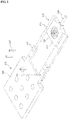
- FIG. 1 is a perspective view showing a long window apparatus according to an embodiment
- FIG. 2 is a view showing the lung window apparatus according to an embodiment when it is separated
- FIG. 3 shows a front view and a bottom view of the lung window apparatus according to an embodiment
- FIG. 4 shows a vertical cross-sectional view of the lung window apparatus according to an embodiment.
- a lung window apparatus may include an open window 100, a suction tube 102, and a tilting mount seat 104.
- the open window has a conical shape with open top and bottom and a diameter is increased from its upper part to its lower part.
- the open window 100 is brought in contact with a lung tissue on the bottom and a cover glass seat 106 is placed over the open window 100.
- a cover glass 110 is placed on the cover glass seat 106 and an objective lens 120 is placed over the cover glass 110.
- the suction tube 102 extends to a suction device (not shown) from a side of the open window 100.
- a cross-section of a lung tissue is brought in contact with the bottom of the open window 100, the cover glass 110 is placed over the open window 100, and the suction tube 102 is placed on a side of the open window 100, so it is possible to keep the inside of the open window 100 vacuum when obtaining an image.
- the tilting mount seat 104 extends from a side of the open window 100 and has a plurality of fastening holes 130, and a tilting mount 140 is coupled through at least some of the fastening holes 130.
- the tilting mount 140 is a kinematic tilting mount and maintains the lung window apparatus and the objective lens 120 in parallel by adjusting the angle of the lung window apparatus.
- the lung window apparatus may be provided by combining first plate 200 and a second plate 202, which are individual parts, with each other.
- the lung window apparatus comprising the tilting mount seat 104 and the open window 100 by putting the first plate 200 and the second plate 220 such that first protrusions 212 formed on a side of a first body 210 of the first plate 200 and second protrusions 222 formed on a side of a second body 220 of the second plate overlap each other, and then fastening the plates with bolts 230.
- the open window 100 is formed in the first body 210 and the tilting mount seat 104 is formed in the second body 220.
- the first protrusions 212 are smaller in thickness than the first body 220 and the second protrusions 222 are smaller in thickness than the second body 220.
- the first body 210 and the second body 220 may be the same in thickness, and the entire thickness when the first protrusions 212 and the second protrusions 222 overlap each other may be the same as the thickness of the first body 210 and the second body 220.
- the first plate 200 and the second plate 202 have steps, and when the first protrusions 212 and the second protrusion 222 overlap each other, the entire thickness is uniform.
- FIG. 5 is a view showing the configuration of a confocal microscope system and arrangement of the lung window apparatus and the objective lens according to an embodiment.
- a process of obtaining an image according to the embodiment is as follows.
- the angle of the lung window apparatus is adjusted using the tilting mount 140 placed on the tilting mount seat 104 of the lung window apparatus.
- laser beams having a plurality of wavelengths are radiated to a lung tissue through the open window 100 of the lung window apparatus.
- a fluorescent signal excited in the lung tissue is detected through a detector.
- the confocal microscopic system includes four laser sources 500-1 to 500-4 respectively four wavelengths of 405nm, 488nm, 561nm, and 640nm within the visible light band, a polygonal rotation mirror 502, and a galvanometer mirror 504, and generates an XY raster scanning pattern, using these components.
- the confocal microscopic system may comprise a plurality of neutral density filters ND, mirrors M, and Dichroic beam splitters DBS, and beam pass filters BPF and photomultiplier tubes for detecting a fluorescent signal excited in a lung tissue.
- An optical system was designed to have an observation view of 250 ⁇ 250 ⁇ m 2 at the focus when using a ⁇ 40 objective lens (LUCPlanFL, NA0.6; Olympus) and a fluorescent signal was detected and processed by photomultiplier tubes individually and frame grabbers (Matrox, SOLIOS) that are provided for wavelengths such that 2D images having cellular-level resolution and being able to be sectioned in the Z-axial direction could be obtained at a speed of 30 sheets per second.
- LOCPlanFL ⁇ 40 objective lens
- NA0.6 opticallympus
- the lung window apparatus By attaching the lung window apparatus according to an embodiment to the confocal microscope system and radiating laser beams to a lung tissue through an objective lens, it is possible to obtaining cellular-level images in real time through excited fluorescent signals.
- FIG. 6 is a view showing a lung tissue image obtained using a microaspiration-based lung window apparatus and a confocal microscope system according to an embodiment.
- a lung tissue has a pulmonary alveolus and a capillary vessel surrounding the pulmonary alveolus and the capillary vessel has a vascular endothelial cell and a basement membrane covering the vascular endothelial cell.
- a black circular pulmonary alveoli and a capillary vessel (red in FIG. 6A and green in FIG. 6B ) composed of vascular endothelial cells surrounding the lungs are found.
- nuclei green in FIG. 6B .
- type I pulmonary cells type II pulmonary alveoli
- nuclei of macrophages around the pulmonary cells could be found.
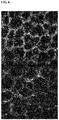
- FIG. 7 is a view showing an image obtained by continuously imaging movement of erythrocyte after injecting FITC-Dextran into a C57BL6/J mouse obtained using a microaspiration-based lung window apparatus and a confocal microscope system according to an embodiment.
- An image for observing movement of erythrocyte and leukocyte was checked in consideration of influence on cells in a lung tissue due to microaspiration.
- An image of erythrocyte contrasted by black was obtained by injecting FITC-Dextran into a blood vessel of the C57BL6/J mouse, and as in FIG. 7 , it was found that movement of the erythrocyte was continued and was not influenced by microaspiration.
- FIG. 8 is a view showing an image obtained by continuously imaging movement of leukocyte in the LysM-GFP mouse obtained using a microaspiration-based lung window apparatus and a confocal microscope system according to an embodiment.
- the apparatus was useful for low-invasive and microscopic access to a lung tissue of an animal model without interfering with physiological circulation. Further, it was found that the apparatus was suitable for securing stable images of lung parenchyma and blood vessels and obtaining images for finding out interaction of cells and single cellular-level movement.
Landscapes
- Health & Medical Sciences (AREA)
- Life Sciences & Earth Sciences (AREA)
- Physics & Mathematics (AREA)
- Engineering & Computer Science (AREA)
- General Health & Medical Sciences (AREA)
- Surgery (AREA)
- Biomedical Technology (AREA)
- Heart & Thoracic Surgery (AREA)
- Medical Informatics (AREA)
- Molecular Biology (AREA)
- Pathology (AREA)
- Animal Behavior & Ethology (AREA)
- Biophysics (AREA)
- Public Health (AREA)
- Veterinary Medicine (AREA)
- Optics & Photonics (AREA)
- Chemical & Material Sciences (AREA)
- Analytical Chemistry (AREA)
- General Physics & Mathematics (AREA)
- Multimedia (AREA)
- Physiology (AREA)
- Pulmonology (AREA)
- Microscoopes, Condenser (AREA)
- Nuclear Medicine, Radiotherapy & Molecular Imaging (AREA)
- Radiology & Medical Imaging (AREA)
- Investigating, Analyzing Materials By Fluorescence Or Luminescence (AREA)
Applications Claiming Priority (2)
| Application Number | Priority Date | Filing Date | Title |
|---|---|---|---|
| KR1020150123216A KR101743283B1 (ko) | 2015-08-31 | 2015-08-31 | 생체 내 폐조직 미세영상 획득을 위한 미세흡인 기반 폐 윈도우 장치 및 이를 이용한 영상 획득 방법 |
| PCT/KR2016/009720 WO2017039316A1 (ko) | 2015-08-31 | 2016-08-31 | 생체 내 폐조직 미세영상 획득을 위한 미세흡인 기반 폐 원도우 장치 및 이를 이용한 영상 획득 방법 |
Publications (4)
| Publication Number | Publication Date |
|---|---|
| EP3345546A1 true EP3345546A1 (de) | 2018-07-11 |
| EP3345546A4 EP3345546A4 (de) | 2019-05-29 |
| EP3345546C0 EP3345546C0 (de) | 2023-10-04 |
| EP3345546B1 EP3345546B1 (de) | 2023-10-04 |
Family
ID=58188002
Family Applications (1)
| Application Number | Title | Priority Date | Filing Date |
|---|---|---|---|
| EP16842282.2A Active EP3345546B1 (de) | 2015-08-31 | 2016-08-31 | Auf mikroaspiration basierende lungenfenstervorrichtung zum erhalt eines mikroskopischen bildes von in-vivo-lungengewebe |
Country Status (6)
| Country | Link |
|---|---|
| US (1) | US10437035B2 (de) |
| EP (1) | EP3345546B1 (de) |
| JP (1) | JP6630831B2 (de) |
| KR (1) | KR101743283B1 (de) |
| CN (1) | CN108601555B (de) |
| WO (1) | WO2017039316A1 (de) |
Families Citing this family (1)
| Publication number | Priority date | Publication date | Assignee | Title |
|---|---|---|---|---|
| CN109030438A (zh) * | 2018-07-06 | 2018-12-18 | 广州蓝勃生物科技有限公司 | 一种用于多波长荧光检测的光路模组 |
Family Cites Families (26)
| Publication number | Priority date | Publication date | Assignee | Title |
|---|---|---|---|---|
| JPS5421752A (en) * | 1977-07-19 | 1979-02-19 | Toshiba Corp | Stage device for microscopes |
| JP3214805B2 (ja) * | 1995-07-17 | 2001-10-02 | シャープ株式会社 | 対物レンズ調整機構 |
| US5907425A (en) * | 1995-12-19 | 1999-05-25 | The Board Of Trustees Of The Leland Stanford Junior University | Miniature scanning confocal microscope |
| AU3493800A (en) * | 1999-02-17 | 2000-09-04 | Lucid, Inc. | Cassette for facilitating optical sectioning of a retained tissue specimen |
| US20060100666A1 (en) * | 2000-04-20 | 2006-05-11 | Pulmosonix Pty. Ltd. | Apparatus and method for lung analysis |
| US6414779B1 (en) * | 2000-11-30 | 2002-07-02 | Opeical Biopsy Technologies, Inc. | Integrated angled-dual-axis confocal scanning endoscopes |
| US6898006B2 (en) * | 2001-12-26 | 2005-05-24 | Olympus Optical Co., Ltd. | Microscope |
| CN1439878A (zh) * | 2003-01-17 | 2003-09-03 | 陕西超英生物医学研究开发有限公司 | 自身抗体检测组织芯片 |
| CN1253716C (zh) * | 2004-01-08 | 2006-04-26 | 中南大学湘雅医学院肿瘤研究所 | 一种用于肿瘤早期诊断的组织芯片及制备器具 |
| US7761129B2 (en) | 2004-05-11 | 2010-07-20 | Koninklijke Philips Electronics N.V. | Measurement head for non-invasive blood analysis |
| US7945077B2 (en) * | 2005-11-30 | 2011-05-17 | Lawrence Livermore National Security, Llc | Hyperspectral microscope for in vivo imaging of microstructures and cells in tissues |
| JP5268282B2 (ja) * | 2007-05-15 | 2013-08-21 | 有限会社 楠屋 | 個体内部の組織学的イメージ像を観察・取得する方法 |
| JP4996977B2 (ja) * | 2007-05-25 | 2012-08-08 | オリンパス株式会社 | スタビライザおよび生体観察装置 |
| US7906076B2 (en) * | 2007-07-02 | 2011-03-15 | University Of Massachusetts | Method and apparatus for biopsy sample processing |
| US8206315B2 (en) * | 2008-09-30 | 2012-06-26 | Suros Surgical Systems, Inc. | Real-time pathology |
| KR101042505B1 (ko) * | 2008-11-27 | 2011-06-16 | 현대제철 주식회사 | 주사 전자 현미경의 시편 홀더장치 |
| CN101872064B (zh) * | 2009-04-24 | 2012-07-04 | 陈亮嘉 | 线型多波长共焦显微镜模块以及其共焦显微方法与系统 |
| CN102297873A (zh) * | 2011-05-03 | 2011-12-28 | 杭州一二八医院 | 利用软x射线显微成像进行癌细胞图形识别的方法 |
| CN202075487U (zh) * | 2011-06-03 | 2011-12-14 | 江南大学 | 自平行读数显微镜 |
| JP5930364B2 (ja) * | 2011-11-28 | 2016-06-08 | 国立大学法人京都大学 | 生体試料固定器 |
| WO2013109624A2 (en) * | 2012-01-17 | 2013-07-25 | Mayo Foundation For Medical Education And Research | Probe-based confocal laser endomicroscopy |
| JP6037732B2 (ja) * | 2012-09-03 | 2016-12-07 | オリンパス株式会社 | 浸液保持具、観察部位固定装置、及び、顕微鏡 |
| CN103202696B (zh) * | 2013-03-06 | 2014-12-17 | 王胜昱 | 基于气溶胶呼出气检测肺部疾病的建模方法 |
| US10007102B2 (en) * | 2013-12-23 | 2018-06-26 | Sakura Finetek U.S.A., Inc. | Microscope with slide clamping assembly |
| US20160095532A1 (en) * | 2014-10-03 | 2016-04-07 | Weinberg Medical Physics Llc | Method and components for in vivo determination of malignancy |
| WO2016200985A1 (en) * | 2015-06-08 | 2016-12-15 | Trustees Of Tufts College | Imaging system to characterize dynamic changes in cell and particle characteristics |
-
2015
- 2015-08-31 KR KR1020150123216A patent/KR101743283B1/ko active IP Right Grant
-
2016
- 2016-08-31 WO PCT/KR2016/009720 patent/WO2017039316A1/ko active Application Filing
- 2016-08-31 US US15/756,478 patent/US10437035B2/en active Active
- 2016-08-31 JP JP2018530459A patent/JP6630831B2/ja active Active
- 2016-08-31 EP EP16842282.2A patent/EP3345546B1/de active Active
- 2016-08-31 CN CN201680062597.XA patent/CN108601555B/zh active Active
Also Published As
| Publication number | Publication date |
|---|---|
| WO2017039316A8 (ko) | 2018-03-22 |
| EP3345546A4 (de) | 2019-05-29 |
| JP2018526688A (ja) | 2018-09-13 |
| KR20170025998A (ko) | 2017-03-08 |
| KR101743283B1 (ko) | 2017-06-02 |
| CN108601555A (zh) | 2018-09-28 |
| US10437035B2 (en) | 2019-10-08 |
| EP3345546C0 (de) | 2023-10-04 |
| JP6630831B2 (ja) | 2020-01-15 |
| CN108601555B (zh) | 2021-01-29 |
| EP3345546B1 (de) | 2023-10-04 |
| US20180246311A1 (en) | 2018-08-30 |
| WO2017039316A1 (ko) | 2017-03-09 |
Similar Documents
| Publication | Publication Date | Title |
|---|---|---|
| EP2770899B1 (de) | Gewebe und zellulare bildgebung | |
| Kirkpatrick et al. | Video-rate resonant scanning multiphoton microscopy: An emerging technique for intravital imaging of the tumor microenvironment | |
| US20190072562A1 (en) | System and method for determination of ligand-target binding by multi-photon fluorescence anisotropy microscopy | |
| JPH03115958A (ja) | 生体組織螢光観察装置 | |
| US11029504B2 (en) | Window apparatus for obtaining microscopic image of in vivo breast tissue and method for obtaining image using same | |
| JP2018139614A (ja) | 細胞観察装置及び細胞観察方法 | |
| US10437035B2 (en) | Microaspiration-based lung window apparatus for obtaining microscopic image of in vivo lung tissue and method for obtaining image using same | |
| US20090185980A1 (en) | In vivo drug screening system | |
| EP3868282A1 (de) | Mikroskopisches bildaufnahmesystem von tiefem in-vivo-gewebe und mikroskopisches bildbereitstellungsverfahren dafür | |
| Takahara et al. | Nipkow confocal imaging from deep brain tissues | |
| JP2005301065A (ja) | 観察装置 | |
| Shao et al. | 3D myofibril imaging in live cardiomyocytes via hybrid SHG-TPEF microscopy | |
| KR101767339B1 (ko) | 생체 내 췌장조직 미세영상 획득을 위한 윈도우 장치 및 이를 이용한 영상 획득 방법 | |
| CN104597016B (zh) | 倒置激光共聚焦显微镜动植物活体观测装置及方法 | |
| CN101315332A (zh) | 使用激光测定酶活性的方法和设备 | |
| KR101022803B1 (ko) | 형광영상 및 감마선영상 촬영을 위한 소 동물용 이중영상 촬영장치 | |
| Conci et al. | In vivo label-free tissue histology through a microstructured imaging window | |
| Fan et al. | A Protocol for Transverse Cardiac Slicing and Optical Mapping in Murine Heart | |
| Wood | Engineering Studies Towards Simultaneous Imaging of Membrane Potential and Calcium Transients in Beating Hearts | |
| WO2008067525A2 (en) | Method and apparatus for measuring quantity of a fluorochrome in a biological environment | |
| WO2018225382A1 (ja) | 細胞状態の解析装置および解析方法 | |
| Ramos-Gomes et al. | An Alternative Technique for Monitoring the Live Interaction of Monocytes and Tumor Cells with Nanoparticles in the Mouse Lung | |
| Singh et al. | Confocal Imaging of Intracellular calcium Cycling in the Intact Heart | |
| Stender et al. | Motion compensation of optical mapping signals from rat heart slices | |
| Cao et al. | Live imaging of subcellular structures and cellular processes in mouse intraperitoneal organs |
Legal Events
| Date | Code | Title | Description |
|---|---|---|---|
| STAA | Information on the status of an ep patent application or granted ep patent |
Free format text: STATUS: THE INTERNATIONAL PUBLICATION HAS BEEN MADE |
|
| PUAI | Public reference made under article 153(3) epc to a published international application that has entered the european phase |
Free format text: ORIGINAL CODE: 0009012 |
|
| STAA | Information on the status of an ep patent application or granted ep patent |
Free format text: STATUS: REQUEST FOR EXAMINATION WAS MADE |
|
| 17P | Request for examination filed |
Effective date: 20180312 |
|
| AK | Designated contracting states |
Kind code of ref document: A1 Designated state(s): AL AT BE BG CH CY CZ DE DK EE ES FI FR GB GR HR HU IE IS IT LI LT LU LV MC MK MT NL NO PL PT RO RS SE SI SK SM TR |
|
| AX | Request for extension of the european patent |
Extension state: BA ME |
|
| DAV | Request for validation of the european patent (deleted) | ||
| DAX | Request for extension of the european patent (deleted) | ||
| A4 | Supplementary search report drawn up and despatched |
Effective date: 20190502 |
|
| RIC1 | Information provided on ipc code assigned before grant |
Ipc: A61B 5/00 20060101ALI20190425BHEP Ipc: G02B 21/00 20060101ALI20190425BHEP Ipc: A61B 5/08 20060101AFI20190425BHEP Ipc: G02B 21/36 20060101ALI20190425BHEP |
|
| STAA | Information on the status of an ep patent application or granted ep patent |
Free format text: STATUS: EXAMINATION IS IN PROGRESS |
|
| 17Q | First examination report despatched |
Effective date: 20220517 |
|
| GRAP | Despatch of communication of intention to grant a patent |
Free format text: ORIGINAL CODE: EPIDOSNIGR1 |
|
| STAA | Information on the status of an ep patent application or granted ep patent |
Free format text: STATUS: GRANT OF PATENT IS INTENDED |
|
| INTG | Intention to grant announced |
Effective date: 20230419 |
|
| GRAS | Grant fee paid |
Free format text: ORIGINAL CODE: EPIDOSNIGR3 |
|
| GRAA | (expected) grant |
Free format text: ORIGINAL CODE: 0009210 |
|
| STAA | Information on the status of an ep patent application or granted ep patent |
Free format text: STATUS: THE PATENT HAS BEEN GRANTED |
|
| AK | Designated contracting states |
Kind code of ref document: B1 Designated state(s): AL AT BE BG CH CY CZ DE DK EE ES FI FR GB GR HR HU IE IS IT LI LT LU LV MC MK MT NL NO PL PT RO RS SE SI SK SM TR |
|
| REG | Reference to a national code |
Ref country code: GB Ref legal event code: FG4D |
|
| REG | Reference to a national code |
Ref country code: CH Ref legal event code: EP |
|
| REG | Reference to a national code |
Ref country code: IE Ref legal event code: FG4D |
|
| REG | Reference to a national code |
Ref country code: DE Ref legal event code: R096 Ref document number: 602016083257 Country of ref document: DE |
|
| U01 | Request for unitary effect filed |
Effective date: 20231012 |
|
| U07 | Unitary effect registered |
Designated state(s): AT BE BG DE DK EE FI FR IT LT LU LV MT NL PT SE SI Effective date: 20231023 |
|
| PG25 | Lapsed in a contracting state [announced via postgrant information from national office to epo] |
Ref country code: GR Free format text: LAPSE BECAUSE OF FAILURE TO SUBMIT A TRANSLATION OF THE DESCRIPTION OR TO PAY THE FEE WITHIN THE PRESCRIBED TIME-LIMIT Effective date: 20240105 |
|
| PG25 | Lapsed in a contracting state [announced via postgrant information from national office to epo] |
Ref country code: IS Free format text: LAPSE BECAUSE OF FAILURE TO SUBMIT A TRANSLATION OF THE DESCRIPTION OR TO PAY THE FEE WITHIN THE PRESCRIBED TIME-LIMIT Effective date: 20240204 |
|
| PG25 | Lapsed in a contracting state [announced via postgrant information from national office to epo] |
Ref country code: ES Free format text: LAPSE BECAUSE OF FAILURE TO SUBMIT A TRANSLATION OF THE DESCRIPTION OR TO PAY THE FEE WITHIN THE PRESCRIBED TIME-LIMIT Effective date: 20231004 |
|
| PG25 | Lapsed in a contracting state [announced via postgrant information from national office to epo] |
Ref country code: IS Free format text: LAPSE BECAUSE OF FAILURE TO SUBMIT A TRANSLATION OF THE DESCRIPTION OR TO PAY THE FEE WITHIN THE PRESCRIBED TIME-LIMIT Effective date: 20240204 Ref country code: GR Free format text: LAPSE BECAUSE OF FAILURE TO SUBMIT A TRANSLATION OF THE DESCRIPTION OR TO PAY THE FEE WITHIN THE PRESCRIBED TIME-LIMIT Effective date: 20240105 Ref country code: ES Free format text: LAPSE BECAUSE OF FAILURE TO SUBMIT A TRANSLATION OF THE DESCRIPTION OR TO PAY THE FEE WITHIN THE PRESCRIBED TIME-LIMIT Effective date: 20231004 |