EP3344157B1 - Systems for manipulating medical devices - Google Patents
Systems for manipulating medical devices Download PDFInfo
- Publication number
- EP3344157B1 EP3344157B1 EP16843162.5A EP16843162A EP3344157B1 EP 3344157 B1 EP3344157 B1 EP 3344157B1 EP 16843162 A EP16843162 A EP 16843162A EP 3344157 B1 EP3344157 B1 EP 3344157B1
- Authority
- EP
- European Patent Office
- Prior art keywords
- guidewire
- aspiration
- lumen
- distal end
- catheter
- Prior art date
- Legal status (The legal status is an assumption and is not a legal conclusion. Google has not performed a legal analysis and makes no representation as to the accuracy of the status listed.)
- Active
Links
Images


Classifications
-
- A—HUMAN NECESSITIES
- A61—MEDICAL OR VETERINARY SCIENCE; HYGIENE
- A61B—DIAGNOSIS; SURGERY; IDENTIFICATION
- A61B17/00—Surgical instruments, devices or methods
- A61B17/22—Implements for squeezing-off ulcers or the like on inner organs of the body; Implements for scraping-out cavities of body organs, e.g. bones; for invasive removal or destruction of calculus using mechanical vibrations; for removing obstructions in blood vessels, not otherwise provided for
-
- A—HUMAN NECESSITIES
- A61—MEDICAL OR VETERINARY SCIENCE; HYGIENE
- A61B—DIAGNOSIS; SURGERY; IDENTIFICATION
- A61B17/00—Surgical instruments, devices or methods
- A61B17/32—Surgical cutting instruments
- A61B17/3203—Fluid jet cutting instruments
- A61B17/32037—Fluid jet cutting instruments for removing obstructions from inner organs or blood vessels, e.g. for atherectomy
-
- A—HUMAN NECESSITIES
- A61—MEDICAL OR VETERINARY SCIENCE; HYGIENE
- A61B—DIAGNOSIS; SURGERY; IDENTIFICATION
- A61B17/00—Surgical instruments, devices or methods
- A61B17/32—Surgical cutting instruments
- A61B17/3205—Excision instruments
- A61B17/3207—Atherectomy devices working by cutting or abrading; Similar devices specially adapted for non-vascular obstructions
- A61B17/320758—Atherectomy devices working by cutting or abrading; Similar devices specially adapted for non-vascular obstructions with a rotating cutting instrument, e.g. motor driven
-
- A—HUMAN NECESSITIES
- A61—MEDICAL OR VETERINARY SCIENCE; HYGIENE
- A61B—DIAGNOSIS; SURGERY; IDENTIFICATION
- A61B17/00—Surgical instruments, devices or methods
- A61B2017/00017—Electrical control of surgical instruments
-
- A—HUMAN NECESSITIES
- A61—MEDICAL OR VETERINARY SCIENCE; HYGIENE
- A61B—DIAGNOSIS; SURGERY; IDENTIFICATION
- A61B17/00—Surgical instruments, devices or methods
- A61B2017/00367—Details of actuation of instruments, e.g. relations between pushing buttons, or the like, and activation of the tool, working tip, or the like
- A61B2017/00398—Details of actuation of instruments, e.g. relations between pushing buttons, or the like, and activation of the tool, working tip, or the like using powered actuators, e.g. stepper motors, solenoids
-
- A—HUMAN NECESSITIES
- A61—MEDICAL OR VETERINARY SCIENCE; HYGIENE
- A61B—DIAGNOSIS; SURGERY; IDENTIFICATION
- A61B17/00—Surgical instruments, devices or methods
- A61B2017/0046—Surgical instruments, devices or methods with a releasable handle; with handle and operating part separable
- A61B2017/00469—Surgical instruments, devices or methods with a releasable handle; with handle and operating part separable for insertion of instruments, e.g. guide wire, optical fibre
-
- A—HUMAN NECESSITIES
- A61—MEDICAL OR VETERINARY SCIENCE; HYGIENE
- A61B—DIAGNOSIS; SURGERY; IDENTIFICATION
- A61B17/00—Surgical instruments, devices or methods
- A61B2017/00681—Aspects not otherwise provided for
- A61B2017/00685—Archimedes screw
-
- A—HUMAN NECESSITIES
- A61—MEDICAL OR VETERINARY SCIENCE; HYGIENE
- A61B—DIAGNOSIS; SURGERY; IDENTIFICATION
- A61B17/00—Surgical instruments, devices or methods
- A61B2017/00681—Aspects not otherwise provided for
- A61B2017/00734—Aspects not otherwise provided for battery operated
-
- A—HUMAN NECESSITIES
- A61—MEDICAL OR VETERINARY SCIENCE; HYGIENE
- A61B—DIAGNOSIS; SURGERY; IDENTIFICATION
- A61B17/00—Surgical instruments, devices or methods
- A61B17/22—Implements for squeezing-off ulcers or the like on inner organs of the body; Implements for scraping-out cavities of body organs, e.g. bones; for invasive removal or destruction of calculus using mechanical vibrations; for removing obstructions in blood vessels, not otherwise provided for
- A61B2017/22038—Implements for squeezing-off ulcers or the like on inner organs of the body; Implements for scraping-out cavities of body organs, e.g. bones; for invasive removal or destruction of calculus using mechanical vibrations; for removing obstructions in blood vessels, not otherwise provided for with a guide wire
- A61B2017/22042—Details of the tip of the guide wire
- A61B2017/22044—Details of the tip of the guide wire with a pointed tip
-
- A—HUMAN NECESSITIES
- A61—MEDICAL OR VETERINARY SCIENCE; HYGIENE
- A61B—DIAGNOSIS; SURGERY; IDENTIFICATION
- A61B17/00—Surgical instruments, devices or methods
- A61B17/22—Implements for squeezing-off ulcers or the like on inner organs of the body; Implements for scraping-out cavities of body organs, e.g. bones; for invasive removal or destruction of calculus using mechanical vibrations; for removing obstructions in blood vessels, not otherwise provided for
- A61B2017/22038—Implements for squeezing-off ulcers or the like on inner organs of the body; Implements for scraping-out cavities of body organs, e.g. bones; for invasive removal or destruction of calculus using mechanical vibrations; for removing obstructions in blood vessels, not otherwise provided for with a guide wire
- A61B2017/22049—Means for locking the guide wire in the catheter
-
- A—HUMAN NECESSITIES
- A61—MEDICAL OR VETERINARY SCIENCE; HYGIENE
- A61B—DIAGNOSIS; SURGERY; IDENTIFICATION
- A61B17/00—Surgical instruments, devices or methods
- A61B17/22—Implements for squeezing-off ulcers or the like on inner organs of the body; Implements for scraping-out cavities of body organs, e.g. bones; for invasive removal or destruction of calculus using mechanical vibrations; for removing obstructions in blood vessels, not otherwise provided for
- A61B2017/22079—Implements for squeezing-off ulcers or the like on inner organs of the body; Implements for scraping-out cavities of body organs, e.g. bones; for invasive removal or destruction of calculus using mechanical vibrations; for removing obstructions in blood vessels, not otherwise provided for with suction of debris
-
- A—HUMAN NECESSITIES
- A61—MEDICAL OR VETERINARY SCIENCE; HYGIENE
- A61B—DIAGNOSIS; SURGERY; IDENTIFICATION
- A61B17/00—Surgical instruments, devices or methods
- A61B17/22—Implements for squeezing-off ulcers or the like on inner organs of the body; Implements for scraping-out cavities of body organs, e.g. bones; for invasive removal or destruction of calculus using mechanical vibrations; for removing obstructions in blood vessels, not otherwise provided for
- A61B2017/22094—Implements for squeezing-off ulcers or the like on inner organs of the body; Implements for scraping-out cavities of body organs, e.g. bones; for invasive removal or destruction of calculus using mechanical vibrations; for removing obstructions in blood vessels, not otherwise provided for for crossing total occlusions, i.e. piercing
-
- A—HUMAN NECESSITIES
- A61—MEDICAL OR VETERINARY SCIENCE; HYGIENE
- A61B—DIAGNOSIS; SURGERY; IDENTIFICATION
- A61B2217/00—General characteristics of surgical instruments
- A61B2217/002—Auxiliary appliance
- A61B2217/005—Auxiliary appliance with suction drainage system
-
- A—HUMAN NECESSITIES
- A61—MEDICAL OR VETERINARY SCIENCE; HYGIENE
- A61B—DIAGNOSIS; SURGERY; IDENTIFICATION
- A61B2217/00—General characteristics of surgical instruments
- A61B2217/002—Auxiliary appliance
- A61B2217/007—Auxiliary appliance with irrigation system
Definitions
- Embodiments of the present disclosure comprise systems and methods for manipulating one or more medical devices.
- the medical devices may include elongated medical devices including, but not limited to: guidewires (guide wires), maceration devices, for example maceration devices having an expending element (such as a basket), cutting devices, atherectomy devices, and a variety of different catheter shafts, including solid catheter shafts and hollow catheter shafts.
- Conventional guidewire manual manipulation methods often involve applying torque to the guidewire to aid its passage through tortuous, occluded, or stenosed conduits or vessels. The user may sometimes spin the guidewire within the fingers (e.g., gloved fingers) to create a torque which assists in manipulating the guidewire through the challenging anatomy.
- This technique is sometimes referred to as "helicoptering,” alluding to the spinning blades of a helicopter.
- This technique can be difficult to achieve because the typically small diameter of guidewires makes them difficult to grip. Additionally, it may be difficult to apply necessary friction to the surface of the guidewire to cause them to rotate, because guidewires are often covered with a lubricious coating. For similar reasons, it may be difficult to place a longitudinal force on the guidewires with manual manipulation, including a back-and-forth longitudinal force intended for placing an oscillatory motion on the guidewire.
- FIG. 1 illustrates an embodiment of a guidewire manipulation device 100 which is advanced over a guidewire 102.
- the guidewire 102 is introduced into a blood vessel of the patient (e.g., a femoral artery).
- the manipulation device 100 is slid over the guidewire 102 and selectively locked on to the guidewire 102.
- the user operates the manipulation device 100 to rotate or vibrate the guidewire 102 as appropriate.
- the user activates the manipulation device 100 to rotate the guidewire 102 (i.e., in a counter clockwise direction indicated by arrow 103), thereby causing the distal end of the guidewire 102 to more easily advance through the angled or curved region.
- the distal end of the guidewire 102 reaches an obstruction (e.g., an embolism) but is unable to easily pass.
- the user then activates the guidewire manipulation device 100 to vibrate (e.g., by routing between a clockwise and counter clockwise direction quickly), thereby causing the distal end of the guidewire 102 to pass through the obstruction.
- the device 100 may include a multiple, preprogrammed rotation patterns appropriate for different vessel configurations (e.g., a 180 degree clockwise rotation followed by 180 degree counter-clockwise rotation, a 90 degree clockwise rotation followed by 90 degree counter clockwise rotation or a 30 degree clockwise rotation followed by 180 degree counter clockwise rotation).
- a 180 degree clockwise rotation followed by 180 degree counter-clockwise rotation e.g., a 180 degree clockwise rotation followed by 180 degree counter-clockwise rotation, a 90 degree clockwise rotation followed by 90 degree counter clockwise rotation or a 30 degree clockwise rotation followed by 180 degree counter clockwise rotation.
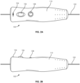
- FIGS. 2A and 2B illustrate external views of the guidewire manipulation device 100.
- the guidewire manipulation device 100 may also include a microprocessor and memory connected to the motor and a button 108 for storing and executing the preprogrammed rotation patterns.
- the guidewire 102 passes through a passage along the length of the guidewire manipulation device 100.
- the guidewire manipulation device 100 includes a locking assembly in the form of a guidewire lock switch 106 which allows the user to selectively lock the guidewire manipulation device 100 to the guidewire 102.
- the guidewire manipulation device 100 can move relative to the guidewire 102 in an unlocked state, and can move the guidewire 102 (rotationally and/or longitudinally) in a locked state.
- the guidewire manipulation device 100 also preferably includes a power indicator light 104 (e.g., an LED) which indicates if the device 100 is powered on and a rotation button 108 which causes the guidewire 102 to rotate. By pressing the button 108, the user activates the device 100.
- the device 100 may include a button, switch or similar mechanism to toggle the device 100 between rotating in a clockwise direction or a counter-clockwise direction.
- the button 108 may include multiple actuation techniques for determining clockwise or counter-clockwise rotation (e.g., sliding forward or backward, multiple button presses, etc.).
- an outer container or casing 110 is composed of a light-weight material such as plastic and has an ergonomic shape that at least partially fits in the user's hand. In this respect, the user can comfortably operate the guidewire manipulation device 100 during a procedure.
- FIGS. 3 and 4 an interior view of the guidewire manipulation device 100 within the outer easing 110 is illustrated according to an embodiment of the present disclosure.
- the guidewire 102 is engaged by the device 100 with elongated rollers 120 (also seen in the cross sectional view of FIG. 5 ).
- the device 100 includes at least three rollers, however, any number of rollers 120 are possible (e.g., 1-5 rollers).
- the button 108 is pressed, the rollers 120 rotate, thereby rotating the guidewire 102.
- the lock switch 106 raises or lowers one or more of the rollers 120 in relation to the guidewire 102, so as to lock the guidewire 102 with the device 100 when the rollers 120 are pressed against the guidewire 102 and unlock the guidewire 102 from the device 100 when the roller(s) 120 are moved away from the guidewire 102.
- One or more of the rollers 120 are preferably driven by a motor 116 which is powered by battery 114 (or alternately by A.C. power such as an outlet).
- the motor 116 connects to the roller(s) 120 by a cam 119 made up of a first linkage 118 connected to the motor 116 and a second linkage 112 connected to the roller(s) 120. In this respect, activation of the motor 116 drives the cam 119 and ultimately rotation of one or more of the rollers 120.
- FIGS. 6 and 7 illustrate another embodiment of a manual manipulation device 130 according to the present disclosure.
- the device 130 is generally similar to the previously described device 100, except that the rollers 120 and therefore rotation at the guidewire 102 is driven by a handle 126.
- depressing the handle 126 rotates the guidewire 102 in a clockwise direction (arrow 122) and releasing the handle 126 rotates the guidewire 102 in a counter clockwise direction (arrow 123).
- a switch 124 is included to change a type of rotation caused by the handle 126.
- the switch 124 may change a gear ratio and therefore the amount of rotation cause by depressing the handle.
- the switch 124 may change directions of rotation caused by depressing the handle 126.
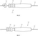
- FIGS. 8 and 9 illustrate another embodiment of a manual guidewire manipulation device 132 which is generally similar to the previously described devices 100 and 130.
- the device 132 includes a selectively locking thumb roller 134 on a distal end of the device 132.
- the thumb roller 134 includes a locked mode, seen in FIG. 8 , in which the roller 134 is engaged with the guidewire 102, thereby allowing the user to roll the roller 134 and thus the guidewire 102.
- the thumb roller 134 also includes an unlocked mode, seen in FIG. 9 , in which the roller 134 is pulled distally from the casing 136, exposing space 138 and disengaging the roller 134 from the guidewire 102.
- the unlocked mode the device 132 can be moved along the length of the guidewire 102.
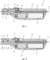
- FIGS. 10-15 illustrate another embodiment of a guidewire manipulation device 140 according to an embodiment of the present disclosure.
- the device 140 is generally similar to the previously described device 100.
- the device 140 includes a hand-held (e.g., configured to be held within a user's hand), ergonomic, outer case 142 and a manipulation button 144.
- the device 140 also includes a motor 152 powered by a battery 154 and a guidewire passage 158 configured for passing the guidewire 102.
- the device 140 includes a locking assembly in the form of a locking hub 146 (similar to the device 132) which allows the user to selectively lock the guidewire 102 with the device 140.
- the locking hub 146 allows free movement of the guidewire 102 when positioned near the case 142 ( FIG. 11 ) and locks the guidewire 102 when the hub is pulled away from the case 142 ( FIG. 12 ).
- the hub 146 includes an interior cavity with a top surface angled downward towards the case 142. Within the interior cavity is a locking wedge 150 which is located within a window 149 of a tube 148 that exposes the guidewire 102. In the unlocked position of FIG.
- the hub 146 restrains the wedge 150 but does not press down on the wedge 150, thereby allowing the guidewire 102 to slide underneath the wedge 150.
- the angled interior surface of the hub 146 forces the wedge downward against the guidewire 102, preventing the guidewire from movement relative to the device 140.
- a perspective view of the wedge 150 can also be seen in FIG. 15 .
- the motor 152 includes a worm 155 that engages a first gear section 156B of shaft 156.
- a worm 156A of shaft 158 engages gearing 148A on the outer surface of tube 148.
- the motor 152 when the motor 152 is activated, it ultimately rotates the roller assembly, or tube 148.
- the hub 146 must be in a slid-out, locked position to cause the guidewire 102 to rotate.
- the device 140 may also include a microprocessor and memory for storing and executing different rotation sequences (i.e., rotation directions and rotation speeds).
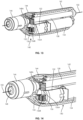
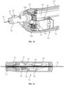
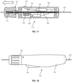
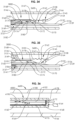
- FIGS. 16 and 17 illustrate a guidewire manipulation device 170 according to yet another embodiment according to the present disclosure.
- the device 170 is generally similar to previously described embodiments, including an outer case 184 having an actuation button 176 that is coupled to a battery 186 and a motor 178.
- the gear 180 of the motor 178 is engaged with a gear 182 that is also engaged with a geared section 181 on wedge tube 174.
- a hub 172 includes an interior, angled passage that increases in diameter in a distal direction.
- the wedge tube 174 is partially positioned within the hub 172.
- the angled passage of the hub 172 complements a distally expanding shape of the wedge tube 174, thereby preventing the wedge tube 172 from clamping or providing force on the guidewire 102 and thus allowing the guidewire 102 to slide and rotate relative to the device 170.
- the hub 172 is moved distally from the case 184, causing the smaller diameter of the interior passage of the hub 172 to wedge or clamp on to the expanded distal end of the wedge tube 174.
- the wedge lobe 174 (preferably composed of a compressible, semi-compressible or deformable material) closes around the guidewire 102, maintaining the position of the guidewire 102 relative to the device 170 and further allowing rotation of the guidewire 102.
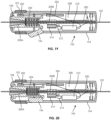
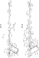
- FIGS. 18-20 illustrates another embodiment of a device 190 according to the present disclosure.
- the device 190 is generally similar to the previously described devices.
- the device 190 includes a locking assembly in the form of a guidewire lock activated by depressing a trigger 196.
- the user can rotate hub 192, either clockwise or counter clockwise to respectively rotate the guidewire 102.
- the device 190 is generally similar to the previously described embodiments, including a motor 210 powered by a battery 208, a gear 214 coupled to an output gear 212 of the motor 210 and to a geared portion 200B of a wedge tube 200 and a case 194 to contain the components.
- the motor 210 is controlled by a rocker switch 192 that is connected to a first circuit board 202 which sends the position of the rocker switch 192 to the second circuit board 206.
- the second circuit board 206 includes a microprocessor and memory for executing a plurality of rotation programs. These rotation programs direct the motor 210 to make predetermined rotation movements such as in a single direction, exponentially increasing rotational speed, quick rotation to cause vibration or a predetermined series of rotational movements. Thus, more complicated movements can be performed by the user.
- the device 190 locks on to the guidewire 102 when the user releases trigger 196 (see FIG. 19 ) and unlocks the guidewire 102 when the user depresses trigger 196.
- the trigger 196 moves an outer tubing 198 which is biased in a distal direction by a spring 204.
- the interior passage of the outer tubing 198 increases in diameter in a distal direction forming an inverted cone shape.
- An inner wedge tube 200 is positioned within the passage of the outer tubing 198 and includes a wedge 200A that increases in size in a distal direction of the device 190.
- the guidewire 102 is located within a passage of the wedge tube 200.
- the outer tubing 198 is moved distally by the spring 204, causing the smaller diameter region of the inner passage of the outer tubing 198 to press against the wedge 200A of wedge tube 200.
- the wedge 200 then compresses around the guidewire 102, locking the guidewire 102 in place relative to the device 190.
- the trigger 196 is depressed, as in FIG. 20 , a portion of the trigger 196 pushes the outer tubing 198 in a proximal direction, against the bias of the spring 204.
- the angled portions of the inner passage of the outer tubing 198 move away from the wedge 200a, allowing the inner passage of the wedge tube 200 to release the guidewire 102.
- the user can selectively lock on to and rotate the guidewire 102 (with the roller assembly, including wedge tube 200) by releasing the trigger 196 and pressing the actuation button 192.
- FIGS. 21 and 22 illustrate another embodiment of a guidewire manipulation device 220 according to the present disclosure.
- the device 220 is generally similar to the previously described embodiments. Including a battery 234 powering a motor 236 which drives a wedge tube 224 (via a gear 240 connected to geared region 224B and output gear 238) and an actuation button 228.
- the device 220 further includes a locking mechanism assembly that locks the lateral position of the guidewire 102. As seen in FIG. 21 , when the user releases the trigger 232, the device remains in a locked position, allowing the user to rotate the guidewire 102. As seen in FIG. 22 , when the user depresses the trigger 232, the device remains in an unlocked position, allowing the user to slide the device 220 along the guidewire 102 and preventing guidewire rotation.
- the trigger 232 maintains an outer tube 222 in a proximal position, proximally biased by a spring 226.
- the outer tube includes an inner passage that generally decreases in diameter in a distal direction. The inner surface of the outer tube 222 presses against a wedge portion 224A of a wedge tube 224, causing the wedge tube 224 to press against and lock onto the guidewire 102.
- the trigger 232 pushes the outer tube 222 distally, against the bias of the spring 226.
- the surface of the inner passage of the outer tube 222 moves away from the wedge 224A, releasing the wedge tube 224 from the guidewire 102.
- the systems and methods disclosed herein further comprise a guidewire manipulation device for selectively imparting motive force (rotational and/or axial/longitudinal (linear) motion) to a guidewire.
- a guidewire manipulation device for selectively locked to a guidewire and is activated to impart motive force to maneuver the guidewire to a desired location during an endovascular procedure.
- the motive force applied to the guidewire is selectively rotational or axial to facilitate moving the guidewire through a vessel and/or penetrating occlusions.
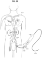
- FIG. 23 illustrates a view of a guidewire manipulation device 2100 being used on a patient 2110 according to one embodiment of the present disclosure.
- the guidewire manipulation device 2100 is a handheld device capable of fitting in the palm of a user's hand and being operated using one hand.
- the guidewire manipulation device 2100 is advanced over a guidewire 2102, i.e., the guidewire 2102 passes through a longitudinally oriented passage in the device 2100.
- the guidewire 2102 is introduced into a vessel 2106 (e.g., a femoral artery) of the patient 2110.
- the guidewire manipulation device 2100 is selectively locked to the guidewire 2102.
- the user operates the manipulation device 2100 to impart motive force (rotational and/or axial motion) to the guidewire 2102, as appropriate.
- the user locks the manipulation device 2100 to the guidewire and imparts rotational motive force to the guidewire 2102 (e.g., in a counter-clockwise direction indicated by arrow 2104), thereby causing the distal end 2108 of the guidewire 2102 to more easily advance through the angled, curved, stenosed, or occluded region of the vessel 2106.
- the device 2100 is unlocked from the guidewire and the guidewire can be further advanced through the vessel.
- the distal end 2108 of the guidewire 2102 reaches an obstruction (e.g., an embolism, including, but not limited to a thromboembolism) but is unable to pass the obstruction.
- an obstruction e.g., an embolism, including, but not limited to a thromboembolism
- the user locks the guidewire manipulation device 2100 to the guidewire 2102 and imparts a vibratory motion (e.g., rapidly oscillating between clockwise and counter-clockwise rotation). Such motion causes the distal end 2108 of the guidewire 2102 to pass through the obstruction.
- the user locks the guidewire manipulation device 2100 to the guidewire 2102 and imparts an axial motion (e.g., a linear movement of the guidewire 2102) to create a jackhammer effect.
- the user may lock the device 2100 to the guidewire 2102 and simultaneously impart both rotational and axial motion to the guidewire 2102.
- a sequence of predefined guidewire manipulations i.e., a pattern
- Various motive patterns to be selectively used in various surgical situations can be selected from memory and applied to the guidewire.
- FIG. 24 depicts a schematic block diagram of one embodiment of a guidewire manipulation device 2100.
- the guidewire manipulation device 2100 defines an axially longitudinal passage 2204 through which the guidewire 2102 is threaded during use.
- the guidewire manipulation device 2100 comprises a housing 2200, an actuator 2206, and a chuck 2202.
- the chuck 2202 comprises a guidewire locking mechanism 2208. During use, the chuck 2202 is locked to the guidewire 2102 using the looking mechanism 2208. Once locked, the actuator selectively imparts motive force (rotational motion and/or axial motion) to the guidewire 2102.
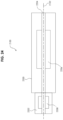
- FIG. 25 depicts a vertical cross-sectional view of one embodiment of a guidewire manipulation device 2100.
- the actuator 2206 of FIG. 24 is divided into a rotary actuator 2206A and an axial actuator 2206B such that the device may selectively apply to the guidewire: no motive force, rotary motive force or rotary and axial motive force.
- Device 2100 comprises a housing 2200 typically formed into halves that are glued, bonded, screwed, or otherwise affixed to each other to form an enclosure.
- a housing 2200 typically formed into halves that are glued, bonded, screwed, or otherwise affixed to each other to form an enclosure.
- the bushings 302A and 302B support an axle 300 on its outer surface 310.
- the axle 300 defines the passage 2204 extending axially through the axle 300.
- the guidewire 2102 is threaded through the passage 2204.
- the rotary actuator 2206A comprises the axle 300, a motor 328, a drive assembly 326, a controller 330, and a control switch 332.
- the drive assembly 326 couples rotational motion of the motor 328 to the axle 300 using a plurality of gears, further described with respect to FIG. 26 below.
- the controller 330 is simply one or more batteries that are coupled to the motor 328 via the control switch 332.
- the control switch 332 may simply apply a voltage from the one or more batteries to the motor 328 to cause the motor 328 to rotate.
- the control switch 332 is a simple single-pole, single-throw (SPST), momentary contact switch.
- the controller 330 comprises a programmable microcontroller as described with respect to FIG. 28 below.
- the switch 332 may apply voltage to cause the motor 328 to selectively rotate clockwise or counter-clockwise.
- the control switch 332 is generally mounted to be exposed to the exterior of the housing 2200 and facilitate manipulation by one hand of a user (e.g., a thumb activated push-button or slide switch.
- the axle 300 is coupled to a chuck 2202.
- the chuck 2202 comprises a coupler 304, a hub 324 and a wedge 314.
- the coupler 304 and the axle 300 have splined mating surfaces 342 for coupling the rotational motion of the axle 300 to the chuck 2202, while allowing the coupler 304 to move in an axial direction.
- the hub 324 is threaded onto the coupler 304 at surface 312.
- the wedge 314 is located in a window 352 defined by the coupler 304.
- the hub 324 retains the wedge 314 within the window 352.
- the hub 324 In a disengaged (unlocked) position, the hub 324 does not impart pressure to the wedge 314 thereby allowing the guidewire 2102 to slide freely beneath the wedge 314 and through the passage 2204.
- the hub 324 To lock (engage) the guidewire into the lock mechanism 2208, the hub 324 is rotated relative to the coupler 304 such that the angled surface 316 of the hub 324 interacts with the top surface 308 of the wedge 314.
- the wedge 314 As the hub 324 is moved relative to the coupler 304 via the mating threaded surfaces 312, the wedge 314 is forced against the guidewire 2102. Consequently, the guidewire 2102 is captured between the wedge 314 and the coupler 304 and thereby locked into the chuck 2202.
- any motion of the chuck 2202 e.g., rotational and/or longitudinal
- the coupler 304 comprises a spring seat 354 supporting a first end of a spring 306.
- the second end of spring 306 rests against a flange 322 that extends from the inner surface of the housing 2200.
- the spring 306 is one embodiment of a resilient member that biases the coupler 304 inwardly toward the axle 300.
- the coupler 304 further comprises a flange 320 that extends radially from the outer surface of the coupler 304.
- the flange 320 is positioned along the coupler 304 to limit the amount of axial movement that can be imparted to the chuck 2202.
- the flange 320 abuts the housing flange 322. As such, the spring 306 biases the coupler 304 to maintain contact between the flange 320 and the flange 322.
- the bottom surface 356 of the hub 324 is dimpled.
- the surface 356 interacts with a protrusion 336 extending from the exterior surface of the housing 2200 proximate the surface 356 of the hub 324.
- the spring 306 insures that the protrusion 336 interacts with the dimpled surface 356.
- the hub 324 is rotated relative to the coupler 304 along the threads 312 to decouple the protrusion 336 from the surface 356.
- the locking mechanism 2208 retains the guidewire 2102 such that rotational motion of the axle 300 is imparted to the guidewire 2102 without imparting axial motion.
- the axial motion actuator 2206B comprises the hub 324, spring 306, coupler 304 and the housing 2200.
- FIG. 26 depicts a cross sectional view of the drive assembly 326 of the rotary actuator 2206A taken along line 26-26 of FIG. 25 in accordance with one embodiment of the present disclosure.
- the drive assembly 326 comprises a motor gear 400, an intermediary gear 402 and an axle gear 404.
- the motor 328 of FIG. 25 is coupled to the motor gear 400 to impart rotational motion to the motor gear 400.
- the axle gear 404 is formed as an integral part of this surface of the axle 300 of FIG. 25 .
- the intermediary gear 402 is designed to provide a gear ratio between the motor gear 400 and axle gear 404.
- the diameters and the number of teeth of each gear is considered to be a design choice that will define the speed of rotational motion of the guidewire 2102 as well as the oscillatory speed of the axial motion.
- the motor 328 of FIG. 25 may be coupled to the axle via other forms of drive assemblies, e.g., direct drive, worm gear, and/or the like.
- the specific motor and drive assembly characteristics are considered a design choice to develop specific guidewire rotation speed and torque.
- the drive assembly may be adjustable to facilitate creating specific speed and torque profiles or adjustments. One form of adjustments may be facilitated by the use of a stepper motor that can be controlled with a pulse width modulated signal produced by the controller, as discussed below.
- An alternative embodiment for imparting rotary motive force in selectable directions uses a gear train comprising two larger diameter spur gears mounted on a common shaft that is driven constantly in one direction by an electric motor.
- Each of the two spur gears has a section of its teeth, something over 1/2 its total number, removed. The removed sections of teeth are positioned such that only one or the other of two additional smaller spur gears, each located to be driven by one of these common shaft gears, will be driven at a time.
- the two smaller spur gears are then used one at a time to drive the gear on the axle, but the positioning of one additional gear between just one of these driving gears and the axle gear results in the rotational direction of the axle being reversed when that set is driving the axle gear.
- Another embodiment if only forward and reverse is required without a near constant rotational speed in either direction, has the spur gear on the axle driven by a pivoted 1/4 pie-shaped plate.
- the toothed curved section opposite the pivot near the tip would be configured to have the correct pitch radius to mesh with the axle spur gear.
- This pivoted gear section plate would have, running upwards from its pivot, a slot in its face in which a pin, mounted off-center and a disc, could slide up and down freely. As an electric motor turns this disc in a constant direction, it would cause the pivoted plate to wobble back and forth so that its gear section drives the axle spur gear in one direction and then in the reverse direction.
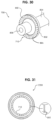
- FIG. 27 depicts a perspective view of the hub 324 in accordance with one embodiment of the present disclosure.
- the hub 324 comprises a surface 356 having a plurality of dimples 504 and spaces 502 between the dimples 504.
- the hub 324 further comprises a threaded interior surface 312.
- the threaded interior surface 312 is adapted to interact with a threaded exterior surface of the coupler 304 to adjust the position of the hub relative to the coupler 304 and the wedge 314.
- the dimples 504 and the spaces 502 between the dimples 504 are adapted to interact with the protrusion 336 to impart axial motion to the chuck 2202.
- the spacing of the dimples and the speed of the motor control the oscillation rate of the axial motion.
- the depth of the dimples 504 relative to the spaces 502 on the surface 356 controls the travel distance of the axial motion.
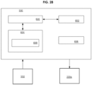
- FIG. 28 depicts a block diagram of the controller 330 in accordance with one embodiment of the present disclosure.
- the controller 330 comprises a microcontroller 600, support circuits 602, memory 604 and a power supply 606.
- the microcontroller 600 may be one or more of many commercially available microcontrollers, microprocessors, application specific integrated circuits (ASIC), and the like.
- the support circuits 602 comprise well known circuits that facilitate the operation of the microcontroller 600 including, but not limited to, clock circuits, cache, power supplies, input/output circuits, indicators, sensors, and/or the like.
- the power supply 606 comprises one or more batteries.
- the power supply 606 may comprise an AC to DC converter to allow the guidewire manipulation device to be plugged into a wall socket.
- the power supply 606 may comprise one or more batteries and a charging circuit for the batteries may be inductively coupled to a base charger.
- the memory 604 may be any form of memory device used to store digital instructions for the microcontroller 600 as well as data.
- the memory 604 is random access memory or read only memory comprising control code 608 (e.g., computer readable instructions) that are used to control the actuator 2206 to impart motion to the guidewire 2102.
- control code 608 e.g., computer readable instructions
- the programs utilized by the microcontroller 600 to control the actuator 2206 are generally controlled by the control switch 332 and/or another input device.
- the motor 328 is a stepper motor that is controlled using, for example, a pulse width modulated signal produced by the controller 330 to impart specific torque and/or speed profiles to the motor 328.
- predefined programs can be generated and selected through manipulation of the switch 332 to enable a user to overcome specific types of obstructions within the path of the guidewire. For example, if a surgeon encounters a specific type of embolism, a specific program defining the motion of the guidewire to overcome the obstruction can be selected and implemented.
- Various programs can be generated through empirical study of guidewire utilization in endovascular procedures. To select a particular motion pattern, the switch may be a slide switch having a plurality of selectable positions, where each position corresponds to a different motion pattern.
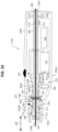
- FIG. 29 depicts a vertical cross-sectional view of a guidewire manipulation device 650 according to an alternative embodiment of the present disclosure.
- the use of axial motion is selected through manipulation of a mechanical switch 702.
- this embodiment selectively imparts to a guidewire: no motive force, rotary motive force, or rotary and axial motive force.
- the device 650 comprises a rotational actuator 2206A as described above with respect to FIG. 25 .
- a coupler 700 comprises a spring seat 750, a dimpled flange 710 and a switch stop 752.
- a slidable switch 702 comprises an extension 704 that interacts with a switch seat 752.
- the switch seat 752 and the spring seat 750 define a space 706 that captures the switch extension 704.
- Manipulation of the switch 702 causes the coupler 700 to move axially along the surface that mates with the axle 300.
- a spring 708 is positioned between the spring seat 750 and the housing flange 322. The spring 708 biases the coupler 700 inwardly toward the axle 300.
- the dimpled flange 710 radially extends from the coupler 700. One surface of the dimpled flange 710 abuts the housing flange 322 to limit the distance the coupler 700 moves in an axial direction.
- the dimpled flange 710 has a surface aligned with a dimpled surface 712 of the housing 2200.
- the guidewire 2102 When the guidewire 2102 is locked to the chuck 2202 and the rotational actuator 2206A is activated, the guidewire 2102 rotates without any axial movement. As described further with respect to FIG. 32 below, when the switch 702 is moved forward to cause the dimpled surface of flange 710 to engage the dimpled surface 712, the guidewire 2102 axial motive force is imparted to the guidewire 2102.
- FIG. 30 depicts a partial perspective view of the coupler 700 in accordance with one embodiment of the present disclosure.
- the coupler 700 has an aperture 806 through which the guidewire 2102 is threaded.
- the dimpled flange 710 comprises a radially extending flange 802 having a plurality of dimples 800 formed in the surface 801.
- the dimples 800 are formed as a sequence of wedges.
- the surface 801 of the flange 802 is varied such that interaction with a corresponding surface causes axial movement of the coupler 700.
- FIG. 31 depicts a cross-sectional view of the housing 2200 taken along line 31-31 in FIG. 29 .
- the surface 712 comprises corresponding protrusions shaped to interact with the dimples 800 in the surface 801 of the coupler 700.
- the surface 712 may comprise complementary wedges 900 to the surface 801 of the coupler 700. The shape of the wedges 900 defines, in part, the distance travelled, the rate of acceleration of the guidewire 2102, and the speed of the oscillation of the guidewire 2102.
- FIG. 32 depicts an embodiment of the guidewire manipulation device 650 of FIG. 29 where the dimpled flange 710 has been engaged the protrusion surface 712.
- the switch 702 has moved the coupler 700 forward to facilitate engagement of the surfaces 710 and 712.
- the guidewire 2102 rotates as shown in arrow 1002 and axially oscillates as represented by arrow 1000.
- FIG. 33 depicts a vertical cross-sectional view of a portion of a guidewire manipulation device 1100.
- Device 1100 comprises an axial actuator 2206B that can be selectively utilized without imparting rotational motion of the guidewire. As such, with this embodiment, the device 1100 selectively imparts to the guide wire: no motive force, rotary motive force, axial motive force, or axial and rotary motive force.
- the device 1100 comprises a linear actuator 1116 coupled to a shaft 1114 that interacts with a fulcrum 1112.
- the linear actuator 1116 imparts linear motion to one portion of the fulcrum 1112.
- the fulcrum is mounted upon a pivot point 1120 such that the fulcrum 1112 rotates about the pivot point 1120 as a linear motive force is applied to the fulcrum 1112.
- a second end of the fulcrum 1112 interacts with a coupler 1104.
- the coupler 110 as with prior embodiments, has a splined surface that interacts with the axle 300 to impart rotational motion to the coupler 1104, as needed.
- the coupler 1104 comprises a spring seat 1108.
- a spring 1106 is positioned between the housing 1102 and the spring seat 1108 to bias the coupler 1104 toward the axle 300.
- the fulcrum 1112 couples to the spring seat 1108 such that motion of the fulcrum 1112 axially moves the coupler 1104. In this manner, without any rotational motion the linear actuator 1116 imparts axial motion to the coupler 1104 and to guidewire 2102 locked in the chuck 2202.
- the linear actuator 1116 may be a solenoid, piezoelectric actuator, linear motor, rotary motor and ball screw or rack/pinion, and/or the like.
- a hammer-drill type assembly may be used to impart axial force to the guidewire.
- the controller 330 in a manner similar to that described for controlling the motor 328 of FIG. 25 may control the linear actuator 1116.
- FIG. 34 shows an open distal end 3158 of an aspiration lumen 3160 of an aspiration catheter 3000 for aspirating thrombus within a blood vessel 3600.
- a skive 3162 may be formed in a polymer jacket 3146 of the aspiration catheter 3000, to aid entry of a thrombus 3164 that is aspirated into the aspiration lumen 3160 (in the direction of arrow 3180) by the combination of the vacuum created by a vacuum source (e.g., VacLok ® Syringe, vacuum bottle) and the injection of fluid into the distal end of the aspiration lumen 3160, as described below.
- the skive 3162 also minimizes the chances of the open distal end 3158 being sucked against a blood vessel wall 3166.
- a distal supply tube 3168 of the aspiration catheter 3000 has a closed distal end 3170.
- it may be occluded during manufacture using adhesive, epoxy, hot melt adhesive or an interference member, such as a metallic or polymeric plug.
- the aspiration catheter 3000 may have a blunt or non-angled tip, instead of the skive 3162.
- the distal supply tube 3168 may be closed off by melting a portion of it.
- the distal supply tube 3168 has a lumen 3176 extending its length and an orifice 3172 formed through its wall 3174 at a location adjacent and proximal to the closed distal end 3170.
- the orifice 3172 may have a diameter between about 0.0508 mm (0.002 inches) and about 0.1016 mm (0.004 inches), or about 0.0787 mm (0.0031 inches).
- the inner diameter of the distal supply tube 3168 may be between about 0.3048 mm (0.012 inches) and about 0.4826 mm (0.019 inches), or between about 0.3556 mm (0.014 inches and about 0.4318 mm (0.017 inches) or about 0.3937 mm (0.0155 inches).
- the lumen 3176 of the distal supply tube 3168 is a continuation of an overall flow path emanating from a fluid source (e.g., saline bag, saline bottle) including an extension tubing (not shown).
- the lumen 3176 of the distal supply tube 3168 may taper, for example, from an inner diameter of about 0.3937 mm (0.0155 inches) at a proximal portion to an inner diameter of about 0.2974 mm (0.011 inches) at a distal portion.
- the equivalent of a taper may be achieved by bonding different diameter tubing to each other, resulting in a stepped-down tubing inner diameter.
- different diameter tapered tubing may be bonded to each other, for a combination of tapering and step-down of diameter.
- An output pressure wave (for example, of saline injected via a pump) causes a liquid injectate to flow through the flow path, including a distal supply tube 3168 (arrow 3182), and causes a fluid jet 3178 to exit the orifice 3172 at a high velocity.
- the fluid jet 3178 serves to macerate thrombus 3164 that is sucked into the aspiration lumen 3160, and also can serve to dilute the thrombus. This maceration and dilution assures that there is continuous flow through the aspiration lumen 3160 so that it will not clog.
- the fluid jet 3178 is configured to be contained within the aspiration lumen 3160, and to not exit into a blood vessel or other body lumen.
- a guidewire tube 3132 having a distal end 3136 and a proximal end 3137 and having a distal port 3139 and a proximal port 3141 is secured to the aspiration catheter 3000 with attachment materials 3186.
- the guidewire tube 3132 of FIG. 34 is shown having a length that is shorter than the length of the aspiration catheter 3000 (sometimes referred to as a rapid exchange catheter), in other embodiments, the guidewire tube 3132 may extend substantially the entire length of the aspiration catheter 3000.
- the aspiration catheter 3000 may have a length of between 100 cm and 180 cm, and the guidewire tube 3132 may have a length of 28 cm or less.
- the guidewire tube 3132 may be a length of 25 cm or less. In some embodiments, the guidewire tube may have a length of 10 cm or less. In some embodiments the guidewire tube may have a length of 3 cm or less. In some embodiments, the guidewire tube may have a length of between about 3 cm and about 28 cm.
- the guidewire tube 3132 may be located adjacent (i.e., lateral) to the aspiration lumen 3160, or may be located co-axially within the aspiration lumen 3160.
- An additional guidewire 3102 may be used along with any aspiration catheter (including, for example, the aspiration catheter 3000) to facilitate the movement of aspirated or macerated thrombus through a catheter lumen, for example, through the aspiration lumen 3160 of the aspiration catheter 3000.
- the guidewire 3102 is secured at its proximal end 3188 ( FIG. 37 ) to any of the embodiments of the guidewire manipulation device 100, 132, 140, 170, 190, 220, 2100, 650, 1100.
- a distal end 3143 includes a straight portion 3145. In embodiments not claimed, the distal end may include a curved portion 3147, or a combination of a straight portion 3145 and a curved portion 3147.
- the guidewire 3102 may include a curved portion 3149 which is not located at the very distal end 3143.
- the curved portion 3147, 3149 may comprise a single arc or multiple arcs, but may generally comprise any non-straight pattern.
- the one or more arcs may be contained within a plane, or they may be three-dimensional.
- the curved portion 3147, 3149 may comprise a helix, such as a single diameter helix or a tapering diameter helix.
- the tapering diameter helix may taper such that the diameter increases as it extends distally, or such that the diameter decreases as it extends distally. In some cases, a fully straight guidewire 3102 may be used.
- either the straight portion 3145 of the distal end 3143 or the curved portion 3147 of the distal end 3143 may be placed adjacent or within the thrombus 3164 by inserting the guidewire 3102 through the aspiration lumen 3160 of the aspiration catheter 3000, and then operating the guidewire manipulation device 100, 132, 140, 170, 190, 220, 2100, 650, 1100 to rotate, longitudinally cycle, or otherwise move the guidewire 3102.
- the movement caused at the distal end 3143 of the guidewire 3102 serves to help to break up or macerate the thrombus 3164, and also help to move the partially or completely macerated thrombus 3164 (or a portion thereof) towards the aspiration catheter 3000 and particularly towards the open distal end 3158 of the aspiration lumen 3160 of the aspiration catheter 3000.
- the curved portion 3149 within the aspiration lumen 3160 of the aspiration catheter 3000 also serves to facilitate the movement of the partially or completely macerated thrombus 3164 (or a portion thereof) through the aspiration lumen 3160 of the aspiration catheter 3000, towards a proximal end of the aspiration lumen 3160.
- the curved portion 3149 may also serve to help center the guidewire 3102 within the aspiration lumen 3160 or to stabilize the guidewire 3102 as it is rotated or longitudinally moved by the guidewire manipulation device 100, 132, 140, 170, 190, 220, 2100, 650, 1100.
- the guidewire 3102 may be slowly pulled proximally during the aspiration of the thrombus 3164, so that the curved portion 3149 helps to translate portions of thrombus.
- the curved portion 3149 may be replaced by a straight portion.
- a guidewire may comprise an outer coil extending along its longitudinal axis, which comprise external contours that will serve to macerate or translate a portion of thrombus.
- the guidewire manipulation device 100, 132, 140, 170, 190, 220, 2100, 650, 1100 may be operated such that the guidewire 3102 is rotated in a direction such that the curved portion 3149 (or the straight portion of helical coil) rotates in a direction that preferentially moves the portion of thrombus proximally in the aspiration lumen, in a similar action to an impeller or Archimedes screw.
- the guidewire manipulation device 100, 132, 140, 170, 190, 220, 2100, 650, 1100 may be attached to a guidewire 3102 that is already in place (i.e., through a guidewire lumen) to guide the catheter, and then the guidewire manipulation device may be activated to move (rotate, longitudinally translate, etc.) the guidewire 3102 to help dislodge the thrombus or other embolus so that it can be fully aspirated/evacuated and removed from the aspiration lumen 3160, thus eliminating the clog.
- the guidewire 3102 or other elongate medical devices may be fabricated from a number of different biocompatible materials, including, but not limited to stainless steels or shape-memory alloys such as nickel-titanium alloys (Nitinol).
- both the aspiration catheter 3000 and the guidewire 3102 may be inserted (separately or together) through a delivery catheter, such as a coronary guiding catheter.
- FIG. 35 illustrates the aspiration catheter 3000 and a guidewire 3102 inserted through a delivery catheter 3151, such as a coronary guiding catheter, but in this case, the guidewire 3102 is radially adjacent the aspiration catheter, within an annulus between the interior of the delivery catheter 3151 and the exterior of the aspiration catheter 3000.
- the guidewire 3102 may be moved or manipulated by the guidewire manipulation device 100, 132, 140, 170, 190, 220, 2100, 650, 1100 such that the distal end 3143 aids the maceration or movement of the thrombus 3164 not only into the aspiration lumen 3160 of the aspiration catheter 3000, but also into the lumen 3153 of the delivery catheter 3151.
- the curved portion 3149 (or a straight portion) is configured to aid the movement of the thrombus 3164 (or a portion thereof) through the lumen 3153 of the delivery catheter 3151.
- the guidewire 3102 may be slowly pulled proximally during the aspiration of the thrombus 3164, so that the curved portion 3149 helps to translate portions of thrombus 3164.
- two guidewires 3102 and two guidewire manipulation devices 100, 132, 140, 170, 190, 220, 2100, 650, 1100 may be used, in a combination of the methods of FIG. 34 and FIG. 35 .
- the aspiration catheters described herein may include any standard aspiration catheter having one or more aspiration lumens. Aspiration catheters used herein may include the ACE TM or INDIGO ® catheters produced by Penumbra, Inc. of Alameda, CA, USA.
- Aspiration catheters and aspiration systems may include those described in U.S. Patent Application Publication No. 2015/0282821 to Look et al., published October 8, 2015 .
- Aspiration catheters and aspiration systems may include those described in U.S. Patent Application Publication No. 2015/0327875 to Look et al., published November 19, 2015 .
- FIG. 38 illustrates a system for treating thrombus 4246.
- the system for treating thrombus 4246 includes a delivery catheter 3151 having a lumen 3153 through which an aspiration catheter 3000 is placed.
- a guidewire 3102 may be inserted either through the lumen 3153 of the delivery catheter 3151, or (as shown in FIG. 38 ) through a lumen of the aspiration catheter 3000, for example, through the aspiration lumen 3160 of the aspiration catheter 3000.
- the guidewire 3102 is configured to be manipulated (rotationally and/or longitudinally) by a guidewire manipulation device 4231 having a housing 4232 and a handle 4237.
- the guidewire manipulation device 4231 may include any of the embodiments described herein, or may include embodiments of guidewire manipulation devices such as those disclosed in co-pending U.S. patent application Ser. No. 15/235,920, filed on August 12, 2016 and entitled "System and Method for Manipulating an Elongate Medical Device.”
- the delivery catheter 3151 has a proximal end 3192 and a distal end 3190, with the proximal end 3192 coupled to a y-connector 4244 by a luer connection 4248.
- the luer connection 4248 may include in some embodiments a female luer attached to the proximal end 3192 of the delivery catheter 3151 and a male luer at the distal end of the y-connector 4244.
- a hemostasis valve 4250 at the proximal end of the y-connector 4244 is configured to seal around a shaft 4252 of the aspiration catheter 3000, and may include a Touhy-Borst, a spring-loaded seal, a duckbill seal, or other seals.
- a connector 4254 is attached to the proximal end 4256 of the aspiration catheter 3000.
- the connector 4254 includes a central bore 4258 which is in fluid communication with the aspiration lumen 3160, and which terminates in a connector 4261 (for example, a female luer connector).
- a port 4260 is in fluid communication with the lumen 3176 of the distal supply tube 3168 ( FIG. 34 ).
- the port 4260 may be configured to be coupled to a source of pressurized fluid 4268 (e.g., normal saline).
- the connector 4261 is configured to be coupled to a connector 4263 at the distal end of a y-connector 4265.
- the connector 4263 may comprise a male luer.
- the y-connector 4265 includes a hemostasis valve 4267 (Touhy-Borst, spring-loaded seal, etc.) and a sideport 4269.
- the hemostasis valve 4267 is configured to seal around the guidewire 3102.
- the sideport 4269 of the y-connector 4265 is configured to be coupled to a vacuum source 4266.
- the sideport 4262 of y-connector 4244 may additionally be configured to be coupled to a vacuum source 4270, and/or may be used for injections of fluids, such as contrast media.
- the aspiration catheter 3000 includes an open distal end 3158, which may include a skive 3162.
- the guidewire 3102 is shown in FIG. 38 having a distal end 3143 which includes a curved portion 3147 and a straight portion 3145, though other distal configurations are also contemplated, including curved only or straight only.
- the guidewire 3102 is shown extending through the aspiration lumen 3160 of the aspiration catheter 3000 and proximally through the connector 4254 and through the y-connector 4265.
- the guidewire 3102 may be secured at its proximal end 3188 to a rotatable chuck 4207, which is rotatably carried by the guidewire manipulation device 4231.
- the chuck 4207 may be manipulated to selectively grip and ungrip (engage and unengage, lock and unlock, etc.) the guidewire 3102 via a collet, or any equivalent means.
- the guidewire manipulation device 4231 is configured to be supported by the hand of a user, and includes the handle 4237 which has one or more controls 4243.
- the handle 4237 may extend in a generally perpendicular direction from the axis of the guidewire 3102 as it extends through the housing 4262, and may angle towards a distal end 4236 of the housing 4232 (as shown in FIG. 38 ) in a reverse gun handle grip.
- the handle 4237 may have a standard gun handle grip (see FIG.
- the controls 4243 are shown in FIG. 38 carried on a distally-facing surface 4239 of the handle 4237, and may be configured in this embodiment to be operated by one or more finger of the hand of the user, which may include non-thumb fingers.
- the controls 4243 may include an activation button 4214 which is configured to turn power on an off, for example, to power a motor (not shown) which is configured to rotate and/or longitudinally move the guidewire 3102.
- a control knob 4217 may be configured to increase or decrease a rotation speed (e.g., of the motor) or to select a plurality of different manipulation routines.
- the manipulation routines may be stored within memory that is carried within the guidewire manipulation device 4231, for example, on a circuit board.
- the circuit board may include a controller, as described in relation to the other embodiments herein.
- An exemplary manipulation routine may include rotating the guidewire 3102 in a first rotational direction eight rotations, and then rotating the guidewire 3102 in a second, opposite, rotational direction eight rotations.
- Another manipulation routine may include rotating continuously in a single direction.
- Another manipulation routine may include rotating continuously in one direction while repeatedly translating the guidewire 3102 distally and proximally (longitudinal cycling).
- the controls 4243 may be carried on a proximally-facing surface 4238 of the handle 4237, and may be configured to be operated primarily by the thumb of the hand of the user.
- the motor may be connected to the chuck 4207 directly, or by other drive elements, including gearing, which may be used to change speeds, torques, or rotational directions.
- the drive elements may include those described in relation to any of the embodiments disclosed herein.
- the vacuum source 4266 may be coupled to the sideport 4269 of the y-connector 4265, and thrombus may thus be aspirated through the aspiration lumen 3160 of the aspiration catheter 3000.
- the vacuum source 4266 may comprise a syringe, a vacuum chamber, or a vacuum pump. Syringes with lockable plungers, for example syringes having volumes of between about 20 ml and about 30 ml, may be used as the vacuum source.
- the user may simultaneously or sequentially operate the guidewire manipulation device 4231 to rotate and/or longitudinally move the guidewire 3102, in order to aid the maceration of the thrombus and/or the movement of the thrombus or pieces of the thrombus through the aspiration lumen 3160.
- FIG. 37 illustrates a system for treating thrombus 5200.
- the system for treating thrombus 5200 includes a sheath 5202 having a lumen 5204 passing therethrough through which a microcatheter 5206 is placed.
- a guidewire 3102 may be inserted a lumen 5208 of the microcatheter 5206.
- the guidewire 3102 is configured to be manipulated (rotationally and/or longitudinally) by a guidewire manipulation device 5231 having a housing 5232 and a handle 5237.
- the guidewire manipulation device 5231 may include any of the embodiments described herein, or may include embodiments of guidewire manipulation devices such as those disclosed in co-pending U.S. patent application Ser. No.
Landscapes
- Health & Medical Sciences (AREA)
- Life Sciences & Earth Sciences (AREA)
- Surgery (AREA)
- Animal Behavior & Ethology (AREA)
- General Health & Medical Sciences (AREA)
- Engineering & Computer Science (AREA)
- Biomedical Technology (AREA)
- Heart & Thoracic Surgery (AREA)
- Veterinary Medicine (AREA)
- Public Health (AREA)
- Vascular Medicine (AREA)
- Medical Informatics (AREA)
- Molecular Biology (AREA)
- Nuclear Medicine, Radiotherapy & Molecular Imaging (AREA)
- Orthopedic Medicine & Surgery (AREA)
- Surgical Instruments (AREA)
- Media Introduction/Drainage Providing Device (AREA)
- Cardiology (AREA)
- Oral & Maxillofacial Surgery (AREA)
- Transplantation (AREA)
Priority Applications (1)
| Application Number | Priority Date | Filing Date | Title |
|---|---|---|---|
| EP25167455.2A EP4552589A3 (en) | 2015-09-03 | 2016-09-03 | Systems for manipulating medical devices |
Applications Claiming Priority (4)
| Application Number | Priority Date | Filing Date | Title |
|---|---|---|---|
| US201562214192P | 2015-09-03 | 2015-09-03 | |
| US201662286429P | 2016-01-24 | 2016-01-24 | |
| US15/256,488 US10561440B2 (en) | 2015-09-03 | 2016-09-02 | Systems and methods for manipulating medical devices |
| PCT/US2016/050302 WO2017041062A1 (en) | 2015-09-03 | 2016-09-03 | Systems and methods for manipulating medical devices |
Related Child Applications (1)
| Application Number | Title | Priority Date | Filing Date |
|---|---|---|---|
| EP25167455.2A Division EP4552589A3 (en) | 2015-09-03 | 2016-09-03 | Systems for manipulating medical devices |
Publications (3)
| Publication Number | Publication Date |
|---|---|
| EP3344157A1 EP3344157A1 (en) | 2018-07-11 |
| EP3344157A4 EP3344157A4 (en) | 2018-10-03 |
| EP3344157B1 true EP3344157B1 (en) | 2025-04-02 |
Family
ID=58188622
Family Applications (2)
| Application Number | Title | Priority Date | Filing Date |
|---|---|---|---|
| EP16843162.5A Active EP3344157B1 (en) | 2015-09-03 | 2016-09-03 | Systems for manipulating medical devices |
| EP25167455.2A Pending EP4552589A3 (en) | 2015-09-03 | 2016-09-03 | Systems for manipulating medical devices |
Family Applications After (1)
| Application Number | Title | Priority Date | Filing Date |
|---|---|---|---|
| EP25167455.2A Pending EP4552589A3 (en) | 2015-09-03 | 2016-09-03 | Systems for manipulating medical devices |
Country Status (5)
| Country | Link |
|---|---|
| US (4) | US10561440B2 (cg-RX-API-DMAC7.html) |
| EP (2) | EP3344157B1 (cg-RX-API-DMAC7.html) |
| JP (1) | JP6884972B2 (cg-RX-API-DMAC7.html) |
| CN (2) | CN113662623B (cg-RX-API-DMAC7.html) |
| WO (1) | WO2017041062A1 (cg-RX-API-DMAC7.html) |
Families Citing this family (52)
| Publication number | Priority date | Publication date | Assignee | Title |
|---|---|---|---|---|
| EP2120737B1 (en) | 2007-02-05 | 2020-04-01 | Boston Scientific Limited | Thrombectomy apparatus |
| US9510854B2 (en) | 2008-10-13 | 2016-12-06 | Boston Scientific Scimed, Inc. | Thrombectomy catheter with control box having pressure/vacuum valve for synchronous aspiration and fluid irrigation |
| US10238406B2 (en) | 2013-10-21 | 2019-03-26 | Inari Medical, Inc. | Methods and apparatus for treating embolism |
| US9883877B2 (en) | 2014-05-19 | 2018-02-06 | Walk Vascular, Llc | Systems and methods for removal of blood and thrombotic material |
| US10561440B2 (en) | 2015-09-03 | 2020-02-18 | Vesatek, Llc | Systems and methods for manipulating medical devices |
| AU2016341439B2 (en) | 2015-10-23 | 2021-07-08 | Inari Medical, Inc. | Intravascular treatment of vascular occlusion and associated devices, systems, and methods |
| US10994115B2 (en) * | 2016-02-09 | 2021-05-04 | Oridion Medical 1987 Ltd. | Luer connector with on-board connection indicator |
| CN113368367B (zh) | 2016-02-24 | 2024-03-29 | 禾木(中国)生物工程有限公司 | 柔性增强的神经血管导管 |
| US10492805B2 (en) | 2016-04-06 | 2019-12-03 | Walk Vascular, Llc | Systems and methods for thrombolysis and delivery of an agent |
| WO2018080590A1 (en) | 2016-10-24 | 2018-05-03 | Inari Medical | Devices and methods for treating vascular occlusion |
| US20180207397A1 (en) * | 2017-01-23 | 2018-07-26 | Walk Vascular, Llc | Systems and methods for removal of blood and thrombotic material |
| US11039846B2 (en) | 2017-04-25 | 2021-06-22 | Biosense Webster (Israel) Ltd. | Guidewire manipulator |
| JP6938681B2 (ja) | 2017-05-23 | 2021-09-22 | 朝日インテック株式会社 | 補助ジェット吸引血栓摘出カテーテルおよびその使用方法 |
| CN109316224B (zh) * | 2017-08-01 | 2024-02-09 | 上海蓝脉医疗科技有限公司 | 血栓去除装置 |
| US11559322B2 (en) * | 2017-08-03 | 2023-01-24 | Biosense Webster (Israel) Ltd. | Multi-functional ENT tool |
| US11154314B2 (en) | 2018-01-26 | 2021-10-26 | Inari Medical, Inc. | Single insertion delivery system for treating embolism and associated systems and methods |
| WO2019152727A1 (en) | 2018-02-02 | 2019-08-08 | Kalera Medical, Inc. | Devices and methods for minimally invasive kidney stone removal by combined aspiration and irrigation |
| US11678905B2 (en) * | 2018-07-19 | 2023-06-20 | Walk Vascular, Llc | Systems and methods for removal of blood and thrombotic material |
| EP3817673B1 (en) * | 2018-08-07 | 2024-11-20 | Cardio Flow, Inc. | Atherectomy devices |
| US11766539B2 (en) | 2019-03-29 | 2023-09-26 | Incept, Llc | Enhanced flexibility neurovascular catheter |
| US11712313B2 (en) * | 2019-07-23 | 2023-08-01 | Siemens Medical Solutions Usa, Inc. | Dual manipulation for robotic catheter system |
| US11864779B2 (en) | 2019-10-16 | 2024-01-09 | Inari Medical, Inc. | Systems, devices, and methods for treating vascular occlusions |
| US11439799B2 (en) | 2019-12-18 | 2022-09-13 | Imperative Care, Inc. | Split dilator aspiration system |
| US12201506B2 (en) | 2019-12-18 | 2025-01-21 | Imperative Care, Inc. | Rotatable thrombus engagement tool |
| CN116234508A (zh) | 2020-06-05 | 2023-06-06 | 伊纳里医疗有限公司 | 可再捕获的漏斗导管以及相关联的系统和方法 |
| WO2022174175A1 (en) | 2021-02-15 | 2022-08-18 | Walk Vascular, Llc | Systems and methods for removal of blood and thrombotic material |
| US12274458B2 (en) * | 2021-02-15 | 2025-04-15 | Walk Vascular, Llc | Systems and methods for removal of blood and thrombotic material |
| WO2022187307A1 (en) * | 2021-03-03 | 2022-09-09 | Covidien Lp | Guidewires |
| US11696793B2 (en) | 2021-03-19 | 2023-07-11 | Crossfire Medical Inc | Vascular ablation |
| US12582426B2 (en) | 2021-04-17 | 2026-03-24 | Inquis Medical, Inc. | Apparatuses for removing obstructive material from body lumens |
| US11679195B2 (en) | 2021-04-27 | 2023-06-20 | Contego Medical, Inc. | Thrombus aspiration system and methods for controlling blood loss |
| US12290274B2 (en) * | 2021-05-25 | 2025-05-06 | Arthrex, Inc. | Dynamically controlling a distal window opening in a rotary surgical shaver |
| JP2024524386A (ja) | 2021-06-28 | 2024-07-05 | インクイス メディカル,インコーポレーテッド | 閉塞性物質の除去を制御するための装置および方法 |
| CN113926055B (zh) * | 2021-10-27 | 2023-09-08 | 黄达 | 一种冠心病介入治疗导丝牵引装置 |
| US12558117B2 (en) | 2021-11-03 | 2026-02-24 | Clearstream Technologies Limited | Rotational atherectomy device |
| EP4463083A4 (en) | 2022-01-11 | 2025-12-03 | Inari Medical Inc | DEVICES FOR REMOVING CLOT MATERIAL FROM INTRAVASCULARLY IMPLANTED DEVICES, AND ASSOCIATED SYSTEMS AND METHODS |
| EP4537867A3 (en) | 2022-03-02 | 2025-05-21 | Calyxo, Inc. | Kidney stone treatment system |
| CN119698258A (zh) | 2022-04-22 | 2025-03-25 | 因奎斯医疗公司 | 用于移除凝块的抽取设备 |
| CN114521939B (zh) * | 2022-04-24 | 2022-09-06 | 北京智愈医疗科技有限公司 | 一种自动水刀实现方法及系统 |
| US20230380850A1 (en) * | 2022-05-26 | 2023-11-30 | Neuravi Limited | Funnel aspiration catheter |
| CN115089269B (zh) * | 2022-06-09 | 2024-04-09 | 清华大学 | 旋切式血管减容设备 |
| US20240108412A1 (en) | 2022-09-29 | 2024-04-04 | Calyxo, Inc. | Tool guiding device for kidney stone treatment apparatus |
| AU2023371657A1 (en) | 2022-11-04 | 2025-05-15 | Solvein Inc. | Catheters and related methods for aspiration and controlled delivery of closure agents |
| US11911581B1 (en) | 2022-11-04 | 2024-02-27 | Controlled Delivery Systems, Inc. | Catheters and related methods for the aspiration controlled delivery of closure agents |
| WO2024145533A2 (en) | 2022-12-28 | 2024-07-04 | Inquis Medical, Inc. | Clot sensing methods and apparatuses |
| AU2024207180A1 (en) | 2023-01-09 | 2025-07-17 | Inari Medical, Inc. | Catheter for use with clot treatment systems |
| WO2025088528A1 (en) * | 2023-10-24 | 2025-05-01 | Rapid Medical Ltd. | Actuator control for guidable endovascular mesh device, and applications thereof |
| CN117562629A (zh) * | 2023-11-15 | 2024-02-20 | 上海微创医疗器械(集团)有限公司 | 医用旋磨装置及旋磨方法 |
| WO2025106851A1 (en) | 2023-11-16 | 2025-05-22 | Inari Medical, Inc. | Automatic locking and unlocking vacuum syringes, and associated systems and methods |
| US12171917B1 (en) | 2024-01-08 | 2024-12-24 | Imperative Care, Inc. | Devices for blood capture and reintroduction during aspiration procedure |
| WO2025166320A1 (en) * | 2024-02-01 | 2025-08-07 | University Of Pittsburgh - Of The Commonwealth System Of Higher Education | Handheld oscillating wire torque device |
| WO2025235015A1 (en) | 2024-05-10 | 2025-11-13 | Inari Medical, Inc. | Mechanical thrombectomy assemblies with relief features, and associated devices, systems, and methods |
Family Cites Families (622)
| Publication number | Priority date | Publication date | Assignee | Title |
|---|---|---|---|---|
| US1144268A (en) | 1915-06-22 | Frederick William Vickery | Laying-machine. | |
| US1114268A (en) | 1913-10-14 | 1914-10-20 | Charles Edmund Kells | Method for surgically cleansing wounds and other surfaces. |
| US1148093A (en) | 1915-03-22 | 1915-07-27 | Charles Edmund Kells | Apparatus for surgically cleansing surfaces. |
| US2804075A (en) | 1955-11-14 | 1957-08-27 | Ruth O Borden | Non-clogging surgical aspirator |
| US3007490A (en) | 1958-06-26 | 1961-11-07 | Allis Chalmers Mfg Co | Rotary valve control |
| US3012766A (en) | 1958-10-02 | 1961-12-12 | Bix Company | Heat treating basket |
| US3034018A (en) | 1959-12-18 | 1962-05-08 | Bosch Arma Corp | Transistorized breakerless ignition system |
| US3429313A (en) | 1966-02-01 | 1969-02-25 | Ram Domestic Products Co | Medical drainage pump |
| US3631847A (en) | 1966-03-04 | 1972-01-04 | James C Hobbs | Method and apparatus for injecting fluid into the vascular system |
| NL145136C (cg-RX-API-DMAC7.html) | 1967-07-25 | 1900-01-01 | ||
| US3494363A (en) | 1969-04-01 | 1970-02-10 | Technical Resources Inc | Control for devices used in surgery |
| US3620650A (en) | 1969-12-05 | 1971-11-16 | Robert F Shaw | Gas-disabled liquid-pumping apparatus |
| US3707967A (en) | 1970-10-01 | 1973-01-02 | Tecna Corp | Steady flow regenerative peritoneal dialysis system and method |
| US3693613A (en) | 1970-12-09 | 1972-09-26 | Cavitron Corp | Surgical handpiece and flow control system for use therewith |
| US3847140A (en) | 1971-12-16 | 1974-11-12 | Catheter & Instr Corp | Operating handle for spring guides |
| US3748435A (en) | 1971-12-16 | 1973-07-24 | Welding Research Inc | Wire attitude control |
| US3807401A (en) | 1972-06-21 | 1974-04-30 | Department Of Health Education | Anticoagulating blood suction device |
| US3818913A (en) | 1972-08-30 | 1974-06-25 | M Wallach | Surgical apparatus for removal of tissue |
| US3916892A (en) | 1974-04-29 | 1975-11-04 | Haemonetics Corp | Phlebotomy needle system incorporating means to add anticoagulant and wash liquid |
| US3930505A (en) | 1974-06-24 | 1976-01-06 | Hydro Pulse Corporation | Surgical apparatus for removal of tissue |
| US3918453A (en) | 1974-07-01 | 1975-11-11 | Baxter Laboratories Inc | Surgical suction device |
| US3955573A (en) | 1974-10-11 | 1976-05-11 | Sorenson Research Co., Inc. | Anticoagulant delivery device and method |
| US4030503A (en) | 1975-11-05 | 1977-06-21 | Clark Iii William T | Embolectomy catheter |
| US4274411A (en) | 1979-03-30 | 1981-06-23 | Dotson Robert S Jun | Fluid operated ophthalmic irrigation and aspiration device |
| US4299221A (en) | 1979-09-28 | 1981-11-10 | Stryker Corporation | Irrigation and suction handpiece |
| US4465470A (en) | 1982-06-04 | 1984-08-14 | Kelman Charles D | Apparatus for and method of irrigating and aspirating an eye |
| US4573476A (en) | 1983-11-14 | 1986-03-04 | Ruiz Oscar F | Angiographic catheter |
| US5197951A (en) | 1983-12-14 | 1993-03-30 | Mahurkar Sakharam D | Simple double lumen catheter |
| US4574812A (en) | 1984-04-18 | 1986-03-11 | The Kendall Company | Arterial thrombus detection system and method |
| US5024651A (en) | 1984-05-14 | 1991-06-18 | Surgical Systems & Instruments, Inc. | Atherectomy system with a sleeve |
| US5135531A (en) | 1984-05-14 | 1992-08-04 | Surgical Systems & Instruments, Inc. | Guided atherectomy system |
| US5306244A (en) | 1984-05-14 | 1994-04-26 | Surgical Systems & Instruments, Inc. | Method of guidewire insertion |
| US4957482A (en) | 1988-12-19 | 1990-09-18 | Surgical Systems & Instruments, Inc. | Atherectomy device with a positive pump means |
| US4886490A (en) | 1984-05-14 | 1989-12-12 | Surgical Systems & Instruments, Inc. | Atherectomy catheter system and method of using the same |
| US4842579B1 (en) | 1984-05-14 | 1995-10-31 | Surgical Systems & Instr Inc | Atherectomy device |
| US5007896A (en) | 1988-12-19 | 1991-04-16 | Surgical Systems & Instruments, Inc. | Rotary-catheter for atherectomy |
| US6440148B1 (en) * | 1984-05-14 | 2002-08-27 | Samuel Shiber | Stent unclogging system with stepped spiral |
| US5653696A (en) | 1984-05-14 | 1997-08-05 | Surgical Systems & Instruments, Inc. | Stent unclogging method |
| US5443443A (en) | 1984-05-14 | 1995-08-22 | Surgical Systems & Instruments, Inc. | Atherectomy system |
| US5002553A (en) | 1984-05-14 | 1991-03-26 | Surgical Systems & Instruments, Inc. | Atherectomy system with a clutch |
| US5334211A (en) | 1984-05-14 | 1994-08-02 | Surgical System & Instruments, Inc. | Lumen tracking atherectomy system |
| US4894051A (en) | 1984-05-14 | 1990-01-16 | Surgical Systems & Instruments, Inc. | Atherectomy system with a biasing sleeve and method of using the same |
| US4979939A (en) | 1984-05-14 | 1990-12-25 | Surgical Systems & Instruments, Inc. | Atherectomy system with a guide wire |
| US4883458A (en) | 1987-02-24 | 1989-11-28 | Surgical Systems & Instruments, Inc. | Atherectomy system and method of using the same |
| US4569344A (en) | 1984-07-23 | 1986-02-11 | Ballard Medical Products | Aspirating/ventilating apparatus and method |
| DE8426270U1 (de) | 1984-09-06 | 1985-02-14 | Veltrup, Elmar Michael, Dipl.-Ing., 4150 Krefeld | Vorrichtung zum entfernen von festkoerpern oder ablagerungen aus koerpergefaessen |
| US4790813A (en) | 1984-12-17 | 1988-12-13 | Intravascular Surgical Instruments, Inc. | Method and apparatus for surgically removing remote deposits |
| US4832685A (en) | 1985-06-05 | 1989-05-23 | Coopervision, Inc. | Fluid flow control system and connecting fitting therefor |
| US4700705A (en) | 1985-08-12 | 1987-10-20 | Intravascular Surgical Instruments, Inc. | Catheter based surgical methods and apparatus therefor |
| US4770654A (en) | 1985-09-26 | 1988-09-13 | Alcon Laboratories Inc. | Multimedia apparatus for driving powered surgical instruments |
| US4702733A (en) | 1985-11-22 | 1987-10-27 | Innovative Surgical Products, Inc. | Foot actuated pinch valve and high vacuum source for irrigation/aspiration handpiece system |
| US5135482A (en) | 1985-12-31 | 1992-08-04 | Arnold Neracher | Hydrodynamic device for the elimination of an organic deposit obstructing a vessel of a human body |
| GB8602732D0 (en) | 1986-02-04 | 1986-03-12 | Univ Brunel | Taking samples from patients |
| US4728319A (en) | 1986-03-20 | 1988-03-01 | Helmut Masch | Intravascular catheter |
| DE3715418A1 (de) | 1986-05-08 | 1987-11-12 | Olympus Optical Co | Lithotom |
| US4740203A (en) | 1986-06-05 | 1988-04-26 | Thomas J. Fogarty | Refillable injection device |
| US5527274A (en) | 1986-06-09 | 1996-06-18 | Development Collaborative Corporation | Catheter for chemical contact dissolution of gallstones |
| US4715853A (en) | 1986-09-19 | 1987-12-29 | Ideal Instruments, Inc. | Back-fill syringe |
| US4747821A (en) | 1986-10-22 | 1988-05-31 | Intravascular Surgical Instruments, Inc. | Catheter with high speed moving working head |
| EP0287920B1 (de) | 1987-04-22 | 1991-05-15 | Siemens Aktiengesellschaft | Kolbenpumpe für ein Medikamentendosiergerät |
| US5057098A (en) | 1987-05-01 | 1991-10-15 | Ophthalmocare, Inc. | Apparatus and method for extracting cataract tissue |
| US5011468A (en) | 1987-05-29 | 1991-04-30 | Retroperfusion Systems, Inc. | Retroperfusion and retroinfusion control apparatus, system and method |
| US4857046A (en) | 1987-10-21 | 1989-08-15 | Cordis Corporation | Drive catheter having helical pump drive shaft |
| DE8714529U1 (de) | 1987-10-31 | 1988-12-08 | Lindenberg, Josef, 7500 Karlsruhe | Vorrichtung zur Thromboembolectomie |
| US4854325A (en) | 1987-11-09 | 1989-08-08 | Stevens Robert C | Reciprocating guidewire method |
| US4886507A (en) | 1988-02-01 | 1989-12-12 | Medex, Inc. | Y connector for angioplasty procedure |
| US5073168A (en) | 1988-10-05 | 1991-12-17 | Danforth John W | Y-adaptor and percutaneous sheath for intravascular catheters |
| SE462414B (sv) | 1988-11-15 | 1990-06-25 | Paal Svedman | Instrument foer avlaegsning av vaevnad |
| US5011488A (en) * | 1988-12-07 | 1991-04-30 | Robert Ginsburg | Thrombus extraction system |
| US5129887A (en) | 1988-12-07 | 1992-07-14 | Scimed Life Systems, Inc. | Adjustable manifold for dilatation catheter |
| US5197795A (en) | 1989-06-30 | 1993-03-30 | Gruhn Usa, Inc. | Adjustable-length removably-mountable holder system |
| US5318529A (en) | 1989-09-06 | 1994-06-07 | Boston Scientific Corporation | Angioplasty balloon catheter and adaptor |
| US5055109A (en) | 1989-10-05 | 1991-10-08 | Advanced Cardiovascular Systems, Inc. | Torque transmitting assembly for intravascular devices |
| US5091656A (en) | 1989-10-27 | 1992-02-25 | Storz Instrument Company | Footswitch assembly with electrically engaged detents |
| US5163433A (en) | 1989-11-01 | 1992-11-17 | Olympus Optical Co., Ltd. | Ultrasound type treatment apparatus |
| US5324263A (en) | 1989-11-02 | 1994-06-28 | Danforth Biomedical, Inc. | Low profile high performance interventional catheters |
| US5074841A (en) | 1990-01-30 | 1991-12-24 | Microcision, Inc. | Atherectomy device with helical cutter |
| US5158564A (en) | 1990-02-14 | 1992-10-27 | Angiomed Ag | Atherectomy apparatus |
| NL9000356A (nl) | 1990-02-14 | 1991-09-02 | Cordis Europ | Drainage-catheter. |
| US5084010A (en) * | 1990-02-20 | 1992-01-28 | Devices For Vascular Intervention, Inc. | System and method for catheter construction |
| US5125893A (en) | 1990-04-16 | 1992-06-30 | Dryden Gale E | Suction catheter with wall lumen for irrigation |
| US5073164A (en) | 1990-05-02 | 1991-12-17 | Hollister William H | Suction catheter |
| DE4018736A1 (de) | 1990-06-12 | 1992-01-02 | Wigbert S Prof Dr Med Rau | Hochdruck-aspirationskatheter zur wiedereroeffnung von krankhaft verschlossenen gefaessen |
| US5195954A (en) | 1990-06-26 | 1993-03-23 | Schnepp Pesch Wolfram | Apparatus for the removal of deposits in vessels and organs of animals |
| US5520189A (en) | 1990-07-13 | 1996-05-28 | Coraje, Inc. | Intravascular ultrasound imaging guidewire |
| US6007513A (en) * | 1990-07-17 | 1999-12-28 | Aziz Yehia Anis | Removal of tissue |
| US6676627B1 (en) | 1990-08-06 | 2004-01-13 | Possis Medical, Inc. | Crossflow thrombectomy catheter and system |
| US6129697A (en) | 1990-08-06 | 2000-10-10 | Possis Medical, Inc. | Thrombectomy and tissue removal device |
| CA2048120A1 (en) | 1990-08-06 | 1992-02-07 | William J. Drasler | Thrombectomy method and device |
| US5078722A (en) | 1990-08-14 | 1992-01-07 | Cordis Corporation | Method and apparatus for removing deposits from a vessel |
| US5064428A (en) | 1990-09-18 | 1991-11-12 | Cook Incorporated | Medical retrieval basket |
| DK1027906T3 (da) | 1990-10-09 | 2005-08-01 | Medtronic Inc | Indretning eller apparat til manipulering af materie |
| US5527292A (en) | 1990-10-29 | 1996-06-18 | Scimed Life Systems, Inc. | Intravascular device for coronary heart treatment |
| CA2095043A1 (en) | 1990-10-29 | 1992-04-30 | Daniel O. Adams | Guide catheter system for angioplasty balloon catheter |
| US5496267A (en) | 1990-11-08 | 1996-03-05 | Possis Medical, Inc. | Asymmetric water jet atherectomy |
| US5916192A (en) | 1991-01-11 | 1999-06-29 | Advanced Cardiovascular Systems, Inc. | Ultrasonic angioplasty-atherectomy catheter and method of use |
| US5234407A (en) | 1991-03-06 | 1993-08-10 | Baxter International Inc. | Method and device for exchanging cardiovascular guide catheter while a previously inserted angioplasty guide wire remains in place |
| JP2939893B2 (ja) | 1991-04-24 | 1999-08-25 | バクスター インターナショナル インコーポレーテッド | 交換可能な一体式−ワイヤーバルーンカテーテル |
| US5290247A (en) | 1991-05-21 | 1994-03-01 | C. R. Bard, Inc. | Intracoronary exchange apparatus and method |
| US5569275A (en) * | 1991-06-11 | 1996-10-29 | Microvena Corporation | Mechanical thrombus maceration device |
| US5284486A (en) * | 1991-06-11 | 1994-02-08 | Microvena Corporation | Self-centering mechanical medical device |
| US5490837A (en) | 1991-07-05 | 1996-02-13 | Scimed Life Systems, Inc. | Single operator exchange catheter having a distal catheter shaft section |
| US5584803A (en) | 1991-07-16 | 1996-12-17 | Heartport, Inc. | System for cardiac procedures |
| US5261877A (en) | 1991-07-22 | 1993-11-16 | Dow Corning Wright | Method of performing a thrombectomy procedure |
| DE4126886A1 (de) | 1991-08-14 | 1993-02-18 | Hp Medica Gmbh | Spuelkatheter |
| US5254085A (en) | 1991-09-19 | 1993-10-19 | Xomed-Treace Inc. | Aspiration system with positive pressure |
| US5571087A (en) | 1992-02-10 | 1996-11-05 | Scimed Life Systems, Inc. | Intravascular catheter with distal tip guide wire lumen |
| US5242404A (en) | 1992-02-12 | 1993-09-07 | American Cyanamid Company | Aspiration control system |
| JP2580816Y2 (ja) | 1992-02-26 | 1998-09-17 | 晴夫 高瀬 | 脂肪等組織吸引用サクションチューブ |
| US5356375A (en) | 1992-04-06 | 1994-10-18 | Namic U.S.A. Corporation | Positive pressure fluid delivery and waste removal system |
| WO1993019679A1 (en) | 1992-04-07 | 1993-10-14 | The Johns Hopkins University | A percutaneous mechanical fragmentation catheter system |
| WO1993020876A1 (en) | 1992-04-14 | 1993-10-28 | Du-Med B.V. | Electronic catheter displacement sensor |
| US5368566A (en) | 1992-04-29 | 1994-11-29 | Cardiovascular Dynamics, Inc. | Delivery and temporary stent catheter having a reinforced perfusion lumen |
| US5322504A (en) | 1992-05-07 | 1994-06-21 | United States Surgical Corporation | Method and apparatus for tissue excision and removal by fluid jet |
| US5389072A (en) | 1992-06-05 | 1995-02-14 | Mircor Biomedical, Inc. | Mechanism for manipulating a tool and flexible elongate device using the same |
| DE4221931C1 (cg-RX-API-DMAC7.html) | 1992-07-03 | 1993-07-08 | Harald Dr. 8521 Moehrendorf De Mang | |
| US5524180A (en) | 1992-08-10 | 1996-06-04 | Computer Motion, Inc. | Automated endoscope system for optimal positioning |
| US5243997A (en) | 1992-09-14 | 1993-09-14 | Interventional Technologies, Inc. | Vibrating device for a guide wire |
| US5524635A (en) * | 1992-09-14 | 1996-06-11 | Interventional Technologies Inc. | Apparatus for advancing a guide wire |
| US5443078A (en) | 1992-09-14 | 1995-08-22 | Interventional Technologies, Inc. | Method for advancing a guide wire |
| US5312427A (en) | 1992-10-16 | 1994-05-17 | Shturman Cardiology Systems, Inc. | Device and method for directional rotational atherectomy |
| JPH06125915A (ja) | 1992-10-21 | 1994-05-10 | Inter Noba Kk | カテーテル式医療機器 |
| US5368555A (en) | 1992-12-29 | 1994-11-29 | Hepatix, Inc. | Organ support system |
| US5626563A (en) | 1993-01-12 | 1997-05-06 | Minnesota Mining And Manufacturing Company | Irrigation system with tubing cassette |
| US5910252A (en) | 1993-02-12 | 1999-06-08 | Cobe Laboratories, Inc. | Technique for extracorporeal treatment of blood |
| US5403276A (en) | 1993-02-16 | 1995-04-04 | Danek Medical, Inc. | Apparatus for minimally invasive tissue removal |
| US5403274A (en) | 1993-03-15 | 1995-04-04 | Cannon; Louis A. | Perfusion catheter and method of use |
| US5327906A (en) | 1993-04-28 | 1994-07-12 | Medtronic, Inc. | Steerable stylet handle |
| US5325868A (en) | 1993-05-04 | 1994-07-05 | Kimmelstiel Carey D | Self-gripping medical wire torquer |
| US5413561A (en) | 1993-05-13 | 1995-05-09 | Cathco, Inc. | Guiding catheter with sealing cap system for reducing blood loss when inserting guiding catheters |
| US5342306A (en) | 1993-05-26 | 1994-08-30 | Don Michael T Anthony | Adjustable catheter device |
| US5342293A (en) | 1993-06-22 | 1994-08-30 | Allergan, Inc. | Variable vacuum/variable flow phacoemulsification method |
| NL9301181A (nl) | 1993-07-05 | 1995-02-01 | Cordis Europ | Werkwijze voor het vervaardigen van een catheter met ten minste één hoge-druklumen en catheter. |
| CA2127637C (en) | 1993-07-26 | 2006-01-03 | Scott Bair | Fluid jet surgical cutting tool |
| US6113576A (en) | 1993-08-04 | 2000-09-05 | Lake Region Manufacturing, Inc. | Thrombolysis catheter system with fixed length infusion zone |
| US5392778A (en) | 1993-08-11 | 1995-02-28 | B. Braun Medical, Inc. | Guidewire torque device for single-hand manipulation |
| WO1995006878A1 (fr) | 1993-08-31 | 1995-03-09 | Aloka Co., Ltd. | Appareil de pipettage dote d'une fonction de detection de fermeture |
| US5577674A (en) | 1993-09-08 | 1996-11-26 | Somat Corporation | Waste pulping and liquid extraction system and method including automatic bag feeding |
| US5419772A (en) | 1993-09-29 | 1995-05-30 | Teitz; Bernard R. | Surgical irrigation apparatus for cleaning and sterilizing wounds and surgical areas during surgery |
| US5462529A (en) | 1993-09-29 | 1995-10-31 | Technology Development Center | Adjustable treatment chamber catheter |
| US5476450A (en) | 1993-11-04 | 1995-12-19 | Ruggio; Joseph M. | Apparatus and method for aspirating intravascular, pulmonary and cardiac obstructions |
| US5605545A (en) | 1994-05-05 | 1997-02-25 | Northgate Technologies Incorporated | Tubing system for delivering fluid to a surgical site |
| JPH07299078A (ja) | 1994-05-09 | 1995-11-14 | Olympus Optical Co Ltd | 内視鏡用電気切開装置 |
| US5478331A (en) | 1994-05-11 | 1995-12-26 | Localmed, Inc. | Multi-function proximal end adapter for catheter |
| WO1996001079A1 (en) | 1994-07-01 | 1996-01-18 | Scimed Life Systems, Inc. | Intravascular device utilizing fluid to extract occlusive material |
| EP1221307B1 (en) | 1994-07-08 | 2010-02-17 | ev3 Inc. | System for performing an intravascular procedure |
| NL9401184A (nl) | 1994-07-19 | 1996-03-01 | Cordis Europ | Zuigcatheter. |
| US5507738A (en) | 1994-08-05 | 1996-04-16 | Microsonic Engineering Devices Company, Inc. | Ultrasonic vascular surgical system |
| US5634475A (en) | 1994-09-01 | 1997-06-03 | Datascope Investment Corp. | Guidewire delivery assist device and system |
| FR2724564B1 (fr) | 1994-09-16 | 1997-04-04 | Boussignac Georges | Dispositif d'assistance respiratoire |
| US5785685A (en) | 1994-09-16 | 1998-07-28 | Scimed Life Systems, Inc. | Balloon catheter with improved pressure source |
| US5647847A (en) | 1994-09-16 | 1997-07-15 | Scimed Life Systems, Inc. | Balloon catheter with improved pressure source |
| US5634933A (en) | 1994-09-29 | 1997-06-03 | Stryker Corporation | Powered high speed rotary surgical handpiece chuck and tools therefore |
| AU3761995A (en) * | 1994-10-03 | 1996-04-26 | Heart Technology, Inc. | Transluminal thrombectomy apparatus |
| US5624394A (en) | 1994-10-28 | 1997-04-29 | Iolab Corporation | Vacuum system and a method of operating a vacuum system |
| US5520635A (en) | 1994-12-16 | 1996-05-28 | Gelbfish; Gary A. | Method and associated device for removing clot |
| DE59609338D1 (de) | 1995-03-28 | 2002-07-18 | Straub Medical Ag Wangs | Katheter zum ablösen von abnormalen ablagerungen in menschlichen blutgefässen |
| US5795322A (en) | 1995-04-10 | 1998-08-18 | Cordis Corporation | Catheter with filter and thrombus-discharge device |
| WO1996035469A1 (en) | 1995-05-10 | 1996-11-14 | Cardiogenesis Corporation | System for treating or diagnosing heart tissue |
| US5827229A (en) | 1995-05-24 | 1998-10-27 | Boston Scientific Corporation Northwest Technology Center, Inc. | Percutaneous aspiration thrombectomy catheter system |
| US5938645A (en) | 1995-05-24 | 1999-08-17 | Boston Scientific Corporation Northwest Technology Center Inc. | Percutaneous aspiration catheter system |
| US5944686A (en) | 1995-06-07 | 1999-08-31 | Hydrocision, Inc. | Instrument for creating a fluid jet |
| US6216573B1 (en) | 1995-06-07 | 2001-04-17 | Hydrocision, Inc. | Fluid jet cutting system |
| US5871462A (en) | 1995-06-07 | 1999-02-16 | Hydrocision, Inc. | Method for using a fluid jet cutting system |
| US5713878A (en) | 1995-06-07 | 1998-02-03 | Surgi-Jet Corporation | Hand tightenable high pressure connector |
| US6027460A (en) | 1995-09-14 | 2000-02-22 | Shturman Cardiology Systems, Inc. | Rotatable intravascular apparatus |
| US5843022A (en) | 1995-10-25 | 1998-12-01 | Scimied Life Systems, Inc. | Intravascular device utilizing fluid to extract occlusive material |
| US5642997A (en) | 1996-02-01 | 1997-07-01 | Gregg, Ii; Robert H. | Laser excisional new attachment procedure |
| US5895398A (en) | 1996-02-02 | 1999-04-20 | The Regents Of The University Of California | Method of using a clot capture coil |
| US5762996A (en) | 1996-04-15 | 1998-06-09 | Lucas; Daniel R. | Silicone balloon catheter |
| NL1003056C2 (nl) | 1996-05-07 | 1997-11-10 | Cordis Europ | Zuigkatheter met hemostase-inrichting. |
| US6019728A (en) | 1996-05-08 | 2000-02-01 | Kabushiki Kaisha Tokai Rika Denki Seisakusho | Catheter and sensor having pressure detecting function |
| US6152909A (en) | 1996-05-20 | 2000-11-28 | Percusurge, Inc. | Aspiration system and method |
| US6958059B2 (en) | 1996-05-20 | 2005-10-25 | Medtronic Ave, Inc. | Methods and apparatuses for drug delivery to an intravascular occlusion |
| US5833644A (en) | 1996-05-20 | 1998-11-10 | Percusurge, Inc. | Method for emboli containment |
| US6022336A (en) | 1996-05-20 | 2000-02-08 | Percusurge, Inc. | Catheter system for emboli containment |
| US6544276B1 (en) | 1996-05-20 | 2003-04-08 | Medtronic Ave. Inc. | Exchange method for emboli containment |
| US6129698A (en) | 1996-05-24 | 2000-10-10 | Beck; Robert C | Catheter |
| US5662671A (en) | 1996-07-17 | 1997-09-02 | Embol-X, Inc. | Atherectomy device having trapping and excising means for removal of plaque from the aorta and other arteries |
| US6569147B1 (en) | 1996-07-26 | 2003-05-27 | Kensey Nash Corporation | Systems and methods of use for delivering beneficial agents for revascularizing stenotic bypass grafts and other occluded blood vessels and for other purposes |
| US6830577B2 (en) | 1996-07-26 | 2004-12-14 | Kensey Nash Corporation | System and method of use for treating occluded vessels and diseased tissue |
| US6652546B1 (en) | 1996-07-26 | 2003-11-25 | Kensey Nash Corporation | System and method of use for revascularizing stenotic bypass grafts and other occluded blood vessels |
| US6905505B2 (en) | 1996-07-26 | 2005-06-14 | Kensey Nash Corporation | System and method of use for agent delivery and revascularizing of grafts and vessels |
| US6080170A (en) | 1996-07-26 | 2000-06-27 | Kensey Nash Corporation | System and method of use for revascularizing stenotic bypass grafts and other occluded blood vessels |
| US5779721A (en) | 1996-07-26 | 1998-07-14 | Kensey Nash Corporation | System and method of use for revascularizing stenotic bypass grafts and other blood vessels |
| US5855567A (en) | 1996-08-22 | 1999-01-05 | Scimed Life Systems, Inc. | Catheter management system |
| US5836909A (en) | 1996-09-13 | 1998-11-17 | Cosmescu; Ioan | Automatic fluid control system for use in open and laparoscopic laser surgery and electrosurgery and method therefor |
| US5730734A (en) | 1996-11-14 | 1998-03-24 | Scimed Life Systems, Inc. | Catheter systems with interchangeable parts |
| US5827243A (en) | 1996-11-29 | 1998-10-27 | Palestrant; Aubrey M. | Collapsible aspiration catheter |
| US6165188A (en) | 1996-12-02 | 2000-12-26 | Angiotrax, Inc. | Apparatus for percutaneously performing myocardial revascularization having controlled cutting depth and methods of use |
| US5810770A (en) | 1996-12-13 | 1998-09-22 | Stryker Corporation | Fluid management pump system for surgical procedures |
| US6146355A (en) | 1996-12-30 | 2000-11-14 | Myelotec, Inc. | Steerable catheter |
| US5893857A (en) | 1997-01-21 | 1999-04-13 | Shturman Cardiology Systems, Inc. | Handle for atherectomy device |
| AU6688398A (en) | 1997-03-06 | 1998-09-22 | Percusurge, Inc. | Intravascular aspiration system |
| US5908395A (en) * | 1997-03-17 | 1999-06-01 | Advanced Cardiovascular Systems, Inc. | Vibrating guidewire |
| US5772674A (en) | 1997-03-31 | 1998-06-30 | Nakhjavan; Fred K. | Catheter for removal of clots in blood vessels |
| DE19717790A1 (de) | 1997-04-26 | 1998-10-29 | Convergenza Ag | Vorrichtung mit einem therapeutischen Katheter |
| US5885244A (en) | 1997-05-14 | 1999-03-23 | Cordis Corporation & University Of Miami | Synchronous, pulsatile angioplasty system |
| US6176844B1 (en) | 1997-05-22 | 2001-01-23 | Peter Y. Lee | Catheter system for the isolation of a segment of blood vessel |
| US6090118A (en) * | 1998-07-23 | 2000-07-18 | Mcguckin, Jr.; James F. | Rotational thrombectomy apparatus and method with standing wave |
| US6179809B1 (en) | 1997-09-24 | 2001-01-30 | Eclipse Surgical Technologies, Inc. | Drug delivery catheter with tip alignment |
| US6554794B1 (en) | 1997-09-24 | 2003-04-29 | Richard L. Mueller | Non-deforming deflectable multi-lumen catheter |
| AU712738B2 (en) | 1997-09-24 | 1999-11-18 | Eclipse Surgical Technologies, Inc. | Steerable catheter |
| US5957901A (en) | 1997-10-14 | 1999-09-28 | Merit Medical Systems, Inc. | Catheter with improved spray pattern for pharmaco-mechanical thrombolysis therapy |
| US6033366A (en) | 1997-10-14 | 2000-03-07 | Data Sciences International, Inc. | Pressure measurement device |
| US5908435A (en) | 1997-10-23 | 1999-06-01 | Samuels; Shaun L. W. | Expandable lumen device and method of use |
| US6156046A (en) | 1997-11-07 | 2000-12-05 | Prolifix Medical, Inc. | Methods and systems for treating obstructions in a body lumen |
| US6183432B1 (en) | 1997-11-13 | 2001-02-06 | Lumend, Inc. | Guidewire and catheter with rotating and reciprocating symmetrical or asymmetrical distal tip |
| US6050986A (en) | 1997-12-01 | 2000-04-18 | Scimed Life Systems, Inc. | Catheter system for the delivery of a low volume liquid bolus |
| US6622367B1 (en) | 1998-02-03 | 2003-09-23 | Salient Interventional Systems, Inc. | Intravascular device and method of manufacture and use |
| US6295990B1 (en) | 1998-02-03 | 2001-10-02 | Salient Interventional Systems, Inc. | Methods and systems for treating ischemia |
| US9586023B2 (en) | 1998-02-06 | 2017-03-07 | Boston Scientific Limited | Direct stream hydrodynamic catheter system |
| US7879022B2 (en) | 1998-02-06 | 2011-02-01 | Medrad, Inc. | Rapid exchange fluid jet thrombectomy device and method |
| US6875193B1 (en) | 1998-02-06 | 2005-04-05 | Possis Medical, Inc. | Rapid exchange fluid jet thrombectomy device and method |
| US6676637B1 (en) | 1998-02-06 | 2004-01-13 | Possis Medical, Inc. | Single operator exchange fluid jet thrombectomy method |
| US5989210A (en) | 1998-02-06 | 1999-11-23 | Possis Medical, Inc. | Rheolytic thrombectomy catheter and method of using same |
| US6224570B1 (en) | 1998-02-06 | 2001-05-01 | Possis Medical, Inc. | Rheolytic thrombectomy catheter and method of using same |
| US20070225615A1 (en) | 2006-03-22 | 2007-09-27 | Revascular Therapeutics Inc. | Guidewire controller system |
| US20060074442A1 (en) | 2000-04-06 | 2006-04-06 | Revascular Therapeutics, Inc. | Guidewire for crossing occlusions or stenoses |
| US6824550B1 (en) | 2000-04-06 | 2004-11-30 | Norbon Medical, Inc. | Guidewire for crossing occlusions or stenosis |
| IL123646A (en) | 1998-03-11 | 2010-05-31 | Refael Beyar | Remote control catheterization |
| US6423032B2 (en) | 1998-03-13 | 2002-07-23 | Arteria Medical Science, Inc. | Apparatus and methods for reducing embolization during treatment of carotid artery disease |
| US6001112A (en) | 1998-04-10 | 1999-12-14 | Endicor Medical, Inc. | Rotational atherectomy device |
| US6666874B2 (en) * | 1998-04-10 | 2003-12-23 | Endicor Medical, Inc. | Rotational atherectomy system with serrated cutting tip |
| US6482217B1 (en) | 1998-04-10 | 2002-11-19 | Endicor Medical, Inc. | Neuro thrombectomy catheter |
| US6190357B1 (en) | 1998-04-21 | 2001-02-20 | Cardiothoracic Systems, Inc. | Expandable cannula for performing cardiopulmonary bypass and method for using same |
| US6293960B1 (en) | 1998-05-22 | 2001-09-25 | Micrus Corporation | Catheter with shape memory polymer distal tip for deployment of therapeutic devices |
| US6579270B2 (en) | 1998-06-04 | 2003-06-17 | Alcon Manufacturing, Ltd. | Liquefracture handpiece tip |
| US6196989B1 (en) | 1998-06-04 | 2001-03-06 | Alcon Laboratories, Inc. | Tip for liquefracture handpiece |
| US6331171B1 (en) | 1998-06-04 | 2001-12-18 | Alcon Laboratories, Inc. | Tip for a liquefracture handpiece |
| FR2779934B1 (fr) | 1998-06-17 | 2001-01-05 | Saphir Medical Sa | Piece a main a commande pneumatique pour applications chirurgicales et medicales |
| US5911722A (en) | 1998-07-23 | 1999-06-15 | Millenium Devices Llc | Leban/Gordon surgical hand driver |
| US6231588B1 (en) | 1998-08-04 | 2001-05-15 | Percusurge, Inc. | Low profile catheter for angioplasty and occlusion |
| US7193521B2 (en) | 1998-10-29 | 2007-03-20 | Medtronic Minimed, Inc. | Method and apparatus for detecting errors, fluid pressure, and occlusions in an ambulatory infusion pump |
| US7621893B2 (en) | 1998-10-29 | 2009-11-24 | Medtronic Minimed, Inc. | Methods and apparatuses for detecting occlusions in an ambulatory infusion pump |
| US7766873B2 (en) | 1998-10-29 | 2010-08-03 | Medtronic Minimed, Inc. | Method and apparatus for detecting occlusions in an ambulatory infusion pump |
| US6283719B1 (en) | 1998-11-05 | 2001-09-04 | Frantz Medical Development Ltd | Detecting obstructions in enteral/parenteral feeding tubes and automatic removal of clogs therefrom |
| US5989271A (en) | 1998-11-09 | 1999-11-23 | Possis Medical, Inc. | Flexible tip rheolytic thrombectomy catheter and method of constructing same |
| US6585705B1 (en) | 1999-01-15 | 2003-07-01 | Maginot Catheter Technologies, Inc. | Retractable catheter systems |
| US6146396A (en) | 1999-03-05 | 2000-11-14 | Board Of Regents, The University Of Texas System | Declotting method and apparatus |
| US6599271B1 (en) | 1999-04-13 | 2003-07-29 | Syntec, Inc. | Ophthalmic flow converter |
| US6238405B1 (en) | 1999-04-30 | 2001-05-29 | Edwards Lifesciences Corp. | Percutaneous material removal device and method |
| US6790215B2 (en) | 1999-04-30 | 2004-09-14 | Edwards Lifesciences Corporation | Method of use for percutaneous material removal device and tip |
| US6918921B2 (en) | 1999-05-07 | 2005-07-19 | Salviac Limited | Support frame for an embolic protection device |
| US6350271B1 (en) | 1999-05-17 | 2002-02-26 | Micrus Corporation | Clot retrieval device |
| US6375635B1 (en) | 1999-05-18 | 2002-04-23 | Hydrocision, Inc. | Fluid jet surgical instruments |
| US6616679B1 (en) | 1999-07-30 | 2003-09-09 | Incept, Llc | Rapid exchange vascular device for emboli and thrombus removal and methods of use |
| JP2001070438A (ja) | 1999-09-02 | 2001-03-21 | Sentan Kagaku Gijutsu Incubation Center:Kk | 生体用精密スクリューポンプ |
| US6702830B1 (en) | 1999-09-17 | 2004-03-09 | Bacchus Vascular, Inc. | Mechanical pump for removal of fragmented matter and methods of manufacture and use |
| US6454775B1 (en) | 1999-12-06 | 2002-09-24 | Bacchus Vascular Inc. | Systems and methods for clot disruption and retrieval |
| US7655016B2 (en) | 1999-09-17 | 2010-02-02 | Covidien | Mechanical pump for removal of fragmented matter and methods of manufacture and use |
| US6615835B1 (en) | 1999-09-20 | 2003-09-09 | Ballard Medical Products | Flexible multiple port adaptor |
| US6554791B1 (en) | 1999-09-29 | 2003-04-29 | Smisson-Cartledge Biomedical, Llc | Rapid infusion system |
| CA2321221A1 (en) | 1999-10-13 | 2001-04-13 | Debra M. Kozak | Crossflow thrombectomy catheter and system |
| AU2614901A (en) | 1999-10-22 | 2001-04-30 | Boston Scientific Corporation | Double balloon thrombectomy catheter |
| US8414543B2 (en) | 1999-10-22 | 2013-04-09 | Rex Medical, L.P. | Rotational thrombectomy wire with blocking device |
| GB9927898D0 (en) | 1999-11-25 | 2000-01-26 | Ssl Int Plc | Irrigation of a hollow body |
| US7494484B2 (en) | 1999-12-10 | 2009-02-24 | Beck Robert C | Method of removing particulate debris with an interventional device |
| EP1241993B1 (en) | 1999-12-22 | 2007-03-28 | Boston Scientific Limited | Endoluminal occlusion-irrigation catheter |
| US6511493B1 (en) | 2000-01-10 | 2003-01-28 | Hydrocision, Inc. | Liquid jet-powered surgical instruments |
| US6451017B1 (en) | 2000-01-10 | 2002-09-17 | Hydrocision, Inc. | Surgical instruments with integrated electrocautery |
| US6663613B1 (en) | 2000-01-25 | 2003-12-16 | Bacchus Vascular, Inc. | System and methods for clot dissolution |
| US6929633B2 (en) * | 2000-01-25 | 2005-08-16 | Bacchus Vascular, Inc. | Apparatus and methods for clot dissolution |
| US6808505B2 (en) | 2000-02-01 | 2004-10-26 | Kadan Jeffrey S | Diagnostic needle arthroscopy and lavage system |
| US7811250B1 (en) | 2000-02-04 | 2010-10-12 | Boston Scientific Scimed, Inc. | Fluid injectable single operator exchange catheters and methods of use |
| US7163504B1 (en) | 2000-02-16 | 2007-01-16 | Advanced Cardiovascular Systems, Inc. | Multi-lumen fluted balloon radiation centering catheter |
| US6752800B1 (en) | 2000-02-18 | 2004-06-22 | Intraluminal Therapeutics Inc. | Catheter handle for controlling the advancement of a guide wire |
| US6719717B1 (en) | 2000-03-17 | 2004-04-13 | Advanced Research & Technology Institute, Inc. | Thrombectomy treatment system and method |
| US20010031981A1 (en) | 2000-03-31 | 2001-10-18 | Evans Michael A. | Method and device for locating guidewire and treating chronic total occlusions |
| DE60121556T2 (de) | 2000-04-05 | 2007-06-28 | Pathway Medical Technologies, Inc., Redmond | System und Verfahren zum Entfernen von intraluminalem Material |
| US7517352B2 (en) * | 2000-04-07 | 2009-04-14 | Bacchus Vascular, Inc. | Devices for percutaneous remote endarterectomy |
| US6533772B1 (en) | 2000-04-07 | 2003-03-18 | Innex Corporation | Guide wire torque device |
| US6544231B1 (en) | 2000-05-22 | 2003-04-08 | Medcanica, Inc. | Catch, stop and marker assembly for a medical instrument and medical instrument incorporating the same |
| EP1289596B1 (en) | 2000-05-31 | 2008-01-16 | Fox Hollow Technologies, Inc. | Embolization protection system for vascular procedures |
| US6824545B2 (en) | 2000-06-29 | 2004-11-30 | Concentric Medical, Inc. | Systems, methods and devices for removing obstructions from a blood vessel |
| WO2002004048A2 (en) | 2000-07-07 | 2002-01-17 | Fluidsense Corporation | Method and apparatus for determining air content and pressure of a liquid in an infusion line |
| US6572578B1 (en) | 2000-08-25 | 2003-06-03 | Patrick A. Blanchard | Fluid-jet catheter and its application to flexible endoscopy |
| US7108674B2 (en) | 2000-08-30 | 2006-09-19 | Radius International Limited Partnership | Catheter |
| WO2002026289A1 (en) | 2000-09-28 | 2002-04-04 | Beck Robert C | Catheter system |
| US7094216B2 (en) | 2000-10-18 | 2006-08-22 | Medrad, Inc. | Injection system having a pressure isolation mechanism and/or a handheld controller |
| US6758824B1 (en) | 2000-11-06 | 2004-07-06 | Suros Surgical Systems, Inc. | Biopsy apparatus |
| US20020058904A1 (en) | 2000-11-08 | 2002-05-16 | Robert Boock | Thrombus removal device |
| JP4276834B2 (ja) | 2000-12-27 | 2009-06-10 | コーニンクレッカ フィリップス エレクトロニクス エヌ ヴィ | 生体情報及び血液処理装置情報管理システム |
| US7766894B2 (en) | 2001-02-15 | 2010-08-03 | Hansen Medical, Inc. | Coaxial catheter system |
| JP3845857B2 (ja) | 2001-03-15 | 2006-11-15 | ニプロ株式会社 | 簡易薬液注入器 |
| US7044958B2 (en) | 2001-04-03 | 2006-05-16 | Medtronic Vascular, Inc. | Temporary device for capturing embolic material |
| US20030065287A1 (en) | 2001-04-03 | 2003-04-03 | Spohn Michael A. | Encoding and sensing of syringe information |
| ES2290293T3 (es) | 2001-04-27 | 2008-02-16 | Hydrocision, Inc. | Cartuchos de bombeo a alta presion para aplicaciones de bombeo e infusion medicas y quirurgicas. |
| US7374560B2 (en) | 2001-05-01 | 2008-05-20 | St. Jude Medical, Cardiology Division, Inc. | Emboli protection devices and related methods of use |
| US7604612B2 (en) | 2001-05-01 | 2009-10-20 | St. Jude Medical, Cardiology Division, Inc. | Emboli protection devices and related methods of use |
| US7422579B2 (en) | 2001-05-01 | 2008-09-09 | St. Jude Medical Cardiology Divison, Inc. | Emboli protection devices and related methods of use |
| US7635342B2 (en) | 2001-05-06 | 2009-12-22 | Stereotaxis, Inc. | System and methods for medical device advancement and rotation |
| DE60229630D1 (de) | 2001-05-06 | 2008-12-11 | Stereotaxis Inc | System zum vorschieben eines Katheter |
| US6623507B2 (en) | 2001-05-07 | 2003-09-23 | Fathy M.A. Saleh | Vascular filtration device |
| DE10123278C1 (de) | 2001-05-10 | 2002-06-13 | Univ Hamburg | Vorrichtung zur Beatmung mit einem Endotrachealtubus |
| US6635070B2 (en) | 2001-05-21 | 2003-10-21 | Bacchus Vascular, Inc. | Apparatus and methods for capturing particulate material within blood vessels |
| JP2003010194A (ja) | 2001-06-29 | 2003-01-14 | Nippon Clean Engine Lab Co Ltd | 液流の逆噴射技術を用いたカテーテルによる血管内施術方法、並びにその装置 |
| US20030013986A1 (en) | 2001-07-12 | 2003-01-16 | Vahid Saadat | Device for sensing temperature profile of a hollow body organ |
| AU2002322520A1 (en) | 2001-07-17 | 2003-03-03 | Kerberos Proximal Solutions | Fluid exchange system for controlled and localized irrigation and aspiration |
| US20050085769A1 (en) | 2001-07-17 | 2005-04-21 | Kerberos Proximal Solutions | Fluid exchange system for controlled and localized irrigation and aspiration |
| US20030023263A1 (en) | 2001-07-24 | 2003-01-30 | Incept Llc | Apparatus and methods for aspirating emboli |
| JP2004537380A (ja) | 2001-08-08 | 2004-12-16 | ハイドロシジョン・インコーポレーテッド | 高圧迅速分離ハンドピースを備えた医療器具 |
| GB2378734A (en) | 2001-08-14 | 2003-02-19 | Carmeli Adahan | Disposable pump with detachable motor |
| US6902540B2 (en) | 2001-08-22 | 2005-06-07 | Gerald Dorros | Apparatus and methods for treating stroke and controlling cerebral flow characteristics |
| CA2499276C (en) | 2001-09-17 | 2008-12-02 | Hydrocision, Inc. | Surgical rotary abrader |
| US20030055404A1 (en) | 2001-09-17 | 2003-03-20 | Moutafis Timothy E. | Endoscopic rotary abraders |
| JP2003101194A (ja) | 2001-09-21 | 2003-04-04 | Hitachi Chem Co Ltd | プリント配線板の製造方法 |
| EP1434611B1 (en) | 2001-10-12 | 2006-06-07 | Coloplast A/S | Sealing device |
| WO2003035142A2 (en) | 2001-10-25 | 2003-05-01 | Emory University | Catheter for modified perfusion |
| CA2495911C (en) | 2001-11-21 | 2011-06-07 | Hydrocision, Inc. | Liquid jet surgical instruments incorporating channel openings aligned along the jet beam |
| US6755812B2 (en) | 2001-12-11 | 2004-06-29 | Cardiac Pacemakers, Inc. | Deflectable telescoping guide catheter |
| GB0130139D0 (en) | 2001-12-18 | 2002-02-06 | Dca Design Int Ltd | Improvements in and relating to a medicament injection apparatus |
| DE10202378B4 (de) | 2002-01-23 | 2005-07-21 | Dürr Dental GmbH & Co. KG | Dentales Behandlungsgerät |
| US7311690B2 (en) | 2002-02-25 | 2007-12-25 | Novashunt Ag | Implantable fluid management system for the removal of excess fluid |
| JP2003260127A (ja) | 2002-03-10 | 2003-09-16 | Nippon Clean Engine Lab Co Ltd | 流体の加圧逆噴射供給による吸引方法とその装置 |
| JP2003290236A (ja) | 2002-04-06 | 2003-10-14 | Nippon Clean Engine Lab Co Ltd | 流体の衝突拡散供給と吸引を行なうカテーテル装置 |
| US20030220556A1 (en) | 2002-05-20 | 2003-11-27 | Vespro Ltd. | Method, system and device for tissue characterization |
| US7179269B2 (en) * | 2002-05-20 | 2007-02-20 | Scimed Life Systems, Inc. | Apparatus and system for removing an obstruction from a lumen |
| US20030236533A1 (en) | 2002-06-20 | 2003-12-25 | The Regents Of The University Of California | Shape memory polymer actuator and catheter |
| US20030236489A1 (en) | 2002-06-21 | 2003-12-25 | Baxter International, Inc. | Method and apparatus for closed-loop flow control system |
| US7831297B2 (en) | 2003-05-24 | 2010-11-09 | Scottsdale Medical Devices, Inc. | Guide wire torque device |
| US7232452B2 (en) | 2002-07-12 | 2007-06-19 | Ev3 Inc. | Device to create proximal stasis |
| US7166120B2 (en) | 2002-07-12 | 2007-01-23 | Ev3 Inc. | Catheter with occluding cuff |
| JP2004049704A (ja) | 2002-07-23 | 2004-02-19 | Nipro Corp | 医療用吸引器 |
| US6893414B2 (en) | 2002-08-12 | 2005-05-17 | Breg, Inc. | Integrated infusion and aspiration system and method |
| US6991625B1 (en) | 2002-08-23 | 2006-01-31 | Medical Components, Inc. | Shielded tip catheter |
| JP2005538383A (ja) | 2002-09-10 | 2005-12-15 | プラコア・インコーポレーテッド | 血小板機能を監視する方法および装置 |
| US20040049225A1 (en) | 2002-09-11 | 2004-03-11 | Denison Andy E. | Aspiration catheter |
| US8298161B2 (en) | 2002-09-12 | 2012-10-30 | Intuitive Surgical Operations, Inc. | Shape-transferring cannula system and method of use |
| US20070167804A1 (en) | 2002-09-18 | 2007-07-19 | Byong-Ho Park | Tubular compliant mechanisms for ultrasonic imaging systems and intravascular interventional devices |
| US7998107B2 (en) | 2002-09-24 | 2011-08-16 | Kensey Nash Corporation | Interventional procedure drive and control system |
| US7993108B2 (en) | 2002-10-09 | 2011-08-09 | Abbott Diabetes Care Inc. | Variable volume, shape memory actuated insulin dispensing pump |
| JP2006502784A (ja) * | 2002-10-18 | 2006-01-26 | シア アリー | 撮像案内ワイヤを備えるアテローム切除システム |
| US8162966B2 (en) | 2002-10-25 | 2012-04-24 | Hydrocision, Inc. | Surgical devices incorporating liquid jet assisted tissue manipulation and methods for their use |
| WO2004041343A1 (en) | 2002-11-04 | 2004-05-21 | Lynn Lawrence A D O | Catheter flushing fluid lock system and method |
| US7115100B2 (en) | 2002-11-15 | 2006-10-03 | Ethicon, Inc. | Tissue biopsy and processing device |
| AU2003295963B2 (en) | 2002-11-25 | 2009-09-03 | Boston Scientific Limited | Injection device for treating mammalian body |
| US7998114B2 (en) | 2003-01-06 | 2011-08-16 | Maquet Cardiovascular Llc | Method and apparatus for regulating pressure during medical procedures |
| US7699804B2 (en) | 2003-01-31 | 2010-04-20 | Creare Inc. | Fluid ejection system |
| EP1445001B1 (en) | 2003-02-07 | 2006-11-22 | Pierpont Family Limited Partnership | Catheter system for performing angioplasty |
| US7393339B2 (en) | 2003-02-21 | 2008-07-01 | C. R. Bard, Inc. | Multi-lumen catheter with separate distal tips |
| US20040181209A1 (en) | 2003-03-14 | 2004-09-16 | Gross James R. | Multiple port catheter connector |
| US7316678B2 (en) | 2003-03-28 | 2008-01-08 | Kensey Nash Corporation | Catheter with associated extension lumen |
| US7776005B2 (en) | 2003-03-28 | 2010-08-17 | Covidien Ag | Triple lumen catheter with occlusion resistant tip |
| US20040199201A1 (en) | 2003-04-02 | 2004-10-07 | Scimed Life Systems, Inc. | Embolectomy devices |
| US20040215222A1 (en) * | 2003-04-25 | 2004-10-28 | Michael Krivoruchko | Intravascular material removal device |
| US7618434B2 (en) | 2003-05-12 | 2009-11-17 | University Of Florida Research Foundation, Inc. | Devices and methods for disruption and removal of luminal occlusions |
| US7862575B2 (en) | 2003-05-21 | 2011-01-04 | Yale University | Vascular ablation apparatus and method |
| US20060129091A1 (en) | 2004-12-10 | 2006-06-15 | Possis Medical, Inc. | Enhanced cross stream mechanical thrombectomy catheter with backloading manifold |
| JP2005006779A (ja) | 2003-06-17 | 2005-01-13 | Terumo Corp | 生体管腔洗浄装置 |
| US7588033B2 (en) | 2003-06-18 | 2009-09-15 | Breathe Technologies, Inc. | Methods, systems and devices for improving ventilation in a lung area |
| US20050004594A1 (en) * | 2003-07-02 | 2005-01-06 | Jeffrey Nool | Devices and methods for aspirating from filters |
| US20050043682A1 (en) | 2003-08-22 | 2005-02-24 | Cannuflow Incorporated | Flexible inflow/outflow cannula and flexible instrument port |
| US6969368B2 (en) | 2003-09-02 | 2005-11-29 | The Anspach Effort, Inc. | Suction and directional irrigation apparatus |
| US8317770B2 (en) | 2006-04-06 | 2012-11-27 | Medtronic, Inc. | Systems and methods of identifying catheter malfunctions using pressure sensing |
| US7220269B1 (en) | 2003-11-06 | 2007-05-22 | Possis Medical, Inc. | Thrombectomy catheter system with occluder and method of using same |
| CN104397869B (zh) | 2003-11-07 | 2016-06-08 | 美国无烟烟草有限责任公司 | 烟草组合物 |
| US7744604B2 (en) | 2003-11-13 | 2010-06-29 | Lawrence Livermore National Security, Llc | Shape memory polymer medical device |
| US7887510B2 (en) | 2003-12-08 | 2011-02-15 | Boehringer Laboratories, Inc. | Suction control apparatus and methods for maintaining fluid flow without compromising sterile lines |
| US7976533B2 (en) | 2003-12-22 | 2011-07-12 | Medela Holding Ag | Drainage apparatus and method |
| US7951073B2 (en) | 2004-01-21 | 2011-05-31 | Boston Scientific Limited | Endoscopic device having spray mechanism and related methods of use |
| CN1913935B (zh) | 2004-01-26 | 2010-05-12 | 导管治疗有限公司 | 带有可调环的导管组件 |
| US7857792B2 (en) | 2004-03-05 | 2010-12-28 | Future Medical System S.A. | Cassette for irrigation or aspiration machine for endoscopy |
| US8092483B2 (en) | 2004-03-06 | 2012-01-10 | Medtronic, Inc. | Steerable device having a corewire within a tube and combination with a functional medical component |
| US20070118165A1 (en) | 2004-03-08 | 2007-05-24 | Demello Jonathan R | System and method for removal of material from a blood vessel using a small diameter catheter |
| US7615032B2 (en) | 2004-03-24 | 2009-11-10 | Windcrest Llc | Vascular guidewire control apparatus |
| US7905710B2 (en) | 2004-03-26 | 2011-03-15 | Hospira, Inc. | System and method for improved low flow medical pump delivery |
| US20060063973A1 (en) | 2004-04-21 | 2006-03-23 | Acclarent, Inc. | Methods and apparatus for treating disorders of the ear, nose and throat |
| US20050240120A1 (en) | 2004-04-26 | 2005-10-27 | Modesitt D B | Vise and method of use |
| US8920402B2 (en) | 2004-04-27 | 2014-12-30 | The Spectranetics Corporation | Thrombectomy and soft debris removal device |
| US7959608B2 (en) | 2004-04-27 | 2011-06-14 | The Spectranetics Corporation | Thrombectomy and soft debris removal device |
| KR100560483B1 (ko) | 2004-05-04 | 2006-03-13 | 삼성에스디아이 주식회사 | 이차 전지 |
| JP5129568B2 (ja) | 2004-05-21 | 2013-01-30 | アニシージア・セイフティ・プロダクツ・エルエルシー | 脈管注入ラインから気泡を検出し、除去するためのシステム |
| IL162318A (en) | 2004-06-03 | 2011-07-31 | Tal Wenderow | Transmission for a remote catheterization system |
| US7662144B2 (en) | 2004-06-22 | 2010-02-16 | Boston Scientific Scimed, Inc. | Catheter shaft with improved manifold bond |
| US7931659B2 (en) | 2004-09-10 | 2011-04-26 | Penumbra, Inc. | System and method for treating ischemic stroke |
| US8444668B2 (en) | 2004-09-17 | 2013-05-21 | DePuy Synthes Products, LLC | Expandable vascular occlusion device |
| JP2006087643A (ja) * | 2004-09-24 | 2006-04-06 | Terumo Corp | 血管内異物吸引装置 |
| US7753880B2 (en) | 2004-09-28 | 2010-07-13 | Stryker Corporation | Method of operating a surgical irrigation pump capable of performing a priming operation |
| US7479106B2 (en) | 2004-09-30 | 2009-01-20 | Boston Scientific Scimed, Inc. | Automated control of irrigation and aspiration in a single-use endoscope |
| WO2006039511A2 (en) | 2004-09-30 | 2006-04-13 | Boston Scientific Scimed, Inc. | System and method of obstruction removal |
| US7819887B2 (en) | 2004-11-17 | 2010-10-26 | Rex Medical, L.P. | Rotational thrombectomy wire |
| US20080009784A1 (en) | 2004-11-22 | 2008-01-10 | Leedle John D | Dialysis catheter |
| US20060229550A1 (en) | 2004-12-14 | 2006-10-12 | Hydrocision, Incorporated | Liquid jet surgical instrument |
| US7691095B2 (en) | 2004-12-28 | 2010-04-06 | St. Jude Medical, Atrial Fibrillation Division, Inc. | Bi-directional steerable catheter control handle |
| US20060142630A1 (en) | 2004-12-29 | 2006-06-29 | Attila Meretei | Systems and methods for treating a thrombus in a blood vessel |
| US7491192B2 (en) | 2004-12-30 | 2009-02-17 | C. R. Bard, Inc. | Cardiovascular access catheter with slit valve |
| US7740780B2 (en) | 2005-01-20 | 2010-06-22 | Hamboly M Samy Ahmed | Multitube catheter and method for making the same |
| US9017350B2 (en) * | 2005-01-25 | 2015-04-28 | Covidien Lp | Expandable occlusive structure |
| US20060184186A1 (en) | 2005-02-16 | 2006-08-17 | Medtronic Vascular, Inc. | Drilling guidewire for treating chronic total occlusion |
| US20060253099A1 (en) | 2005-04-21 | 2006-11-09 | Medtronic Vascular, Inc. | Guiding catheter with resiliently compressible occluder |
| US20080097291A1 (en) | 2006-08-23 | 2008-04-24 | Hanson Ian B | Infusion pumps and methods and delivery devices and methods with same |
| IL179618A0 (en) | 2006-11-27 | 2007-10-31 | Eyoca Medical Ltd | Device for inducing vibrations |
| US7938851B2 (en) | 2005-06-08 | 2011-05-10 | Xtent, Inc. | Devices and methods for operating and controlling interventional apparatus |
| EP1909864B1 (en) | 2005-06-13 | 2012-10-17 | Smith & Nephew, Inc. | Surgical fluid management |
| US20070005030A1 (en) | 2005-06-21 | 2007-01-04 | Hopkins Mark A | Aspiration control via flow or impedance |
| WO2007002154A2 (en) | 2005-06-21 | 2007-01-04 | Medrad, Inc. | Medical fluid injection and inflation system |
| US20120330196A1 (en) | 2005-06-24 | 2012-12-27 | Penumbra Inc. | Methods and Apparatus for Removing Blood Clots and Tissue from the Patient's Head |
| US20070016105A1 (en) | 2005-06-27 | 2007-01-18 | Mamourian Alexander C | Wire torque apparatus, wire insertion devices, improved aneurysm clips and improved aneurysm clip applicators |
| US20070078438A1 (en) | 2005-07-05 | 2007-04-05 | Okid Corporation | Catheter assembly and sheath tear assistant tool |
| US8221348B2 (en) | 2005-07-07 | 2012-07-17 | St. Jude Medical, Cardiology Division, Inc. | Embolic protection device and methods of use |
| US8012766B2 (en) | 2005-08-01 | 2011-09-06 | Ortho-Clinical Diagnostics, Inc. | Prediction of aspirated volume of a liquid |
| US8021351B2 (en) | 2005-08-18 | 2011-09-20 | Medtronic Vascular, Inc. | Tracking aspiration catheter |
| US7938820B2 (en) | 2005-08-18 | 2011-05-10 | Lumen Biomedical, Inc. | Thrombectomy catheter |
| GR20050100452A (el) | 2005-09-02 | 2007-04-25 | Estelle Enterprises Limited | Συστημα καθετηρα ανταλλαγης υγρων |
| US7713240B2 (en) | 2005-09-13 | 2010-05-11 | Medtronic Minimed, Inc. | Modular external infusion device |
| US7935077B2 (en) | 2005-09-28 | 2011-05-03 | Medrad, Inc. | Thrombectomy catheter deployment system |
| US8202243B2 (en) | 2005-10-27 | 2012-06-19 | Novartis Ag | Fluid pressure sensing chamber |
| US8398582B2 (en) | 2005-10-27 | 2013-03-19 | Novartis Ag | Fluid pressure sensing chamber |
| US7947039B2 (en) | 2005-12-12 | 2011-05-24 | Covidien Ag | Laparoscopic apparatus for performing electrosurgical procedures |
| WO2007078463A1 (en) | 2005-12-22 | 2007-07-12 | The Trustees Of Columbia University In The City Of New York | Systems and methods for intravascular cooling |
| CN101394877B (zh) | 2006-01-24 | 2011-07-27 | 海德鲁西昂公司 | 远端形状选择性可控的液体喷射外科器械 |
| CN104162200B (zh) | 2006-02-09 | 2018-03-27 | 德卡产品有限公司 | 外围系统 |
| US7608063B2 (en) | 2006-02-23 | 2009-10-27 | Medrad, Inc. | Dual lumen aspiration catheter system |
| US7972282B2 (en) * | 2006-03-20 | 2011-07-05 | Merit Medical Systems, Inc. | Torque device for a medical guidewire |
| US7981073B2 (en) | 2006-03-30 | 2011-07-19 | Moellstam Anders | Method and device for irrigation of body cavities |
| US7846175B2 (en) | 2006-04-03 | 2010-12-07 | Medrad, Inc. | Guidewire and collapsable filter system |
| US20070239182A1 (en) * | 2006-04-03 | 2007-10-11 | Boston Scientific Scimed, Inc. | Thrombus removal device |
| US20070249990A1 (en) | 2006-04-20 | 2007-10-25 | Ioan Cosmescu | Automatic smoke evacuator and insufflation system for surgical procedures |
| WO2007124076A1 (en) | 2006-04-21 | 2007-11-01 | Abbott Laboratories | Guidewire handling device |
| EP2019628A4 (en) | 2006-04-25 | 2014-03-05 | Hydrocision Inc | ELECTROFORMED SURGICAL INSTRUMENT WITH LIQUID SPREAD |
| US8048032B2 (en) | 2006-05-03 | 2011-11-01 | Vascular Solutions, Inc. | Coaxial guide catheter for interventional cardiology procedures |
| US7520858B2 (en) | 2006-06-05 | 2009-04-21 | Physical Logic Ag | Catheter with pressure sensor and guidance system |
| ES2751017T3 (es) | 2006-06-08 | 2020-03-30 | Hoffmann La Roche | Sistema para detectar una oclusión en un tubo |
| US20070299306A1 (en) | 2006-06-21 | 2007-12-27 | Parasher Vinod K | Probe assembly for endoscopic procedures |
| US9492192B2 (en) | 2006-06-30 | 2016-11-15 | Atheromed, Inc. | Atherectomy devices, systems, and methods |
| US9314263B2 (en) | 2006-06-30 | 2016-04-19 | Atheromed, Inc. | Atherectomy devices, systems, and methods |
| US20080004645A1 (en) | 2006-06-30 | 2008-01-03 | Atheromed, Inc. | Atherectomy devices and methods |
| US8007506B2 (en) | 2006-06-30 | 2011-08-30 | Atheromed, Inc. | Atherectomy devices and methods |
| US8628549B2 (en) | 2006-06-30 | 2014-01-14 | Atheromed, Inc. | Atherectomy devices, systems, and methods |
| US20090018566A1 (en) | 2006-06-30 | 2009-01-15 | Artheromed, Inc. | Atherectomy devices, systems, and methods |
| US8361094B2 (en) | 2006-06-30 | 2013-01-29 | Atheromed, Inc. | Atherectomy devices and methods |
| GB0613981D0 (cg-RX-API-DMAC7.html) | 2006-07-13 | 2006-08-23 | Shturman Leonid | |
| EP2073884B1 (en) | 2006-08-02 | 2018-10-10 | Osprey Medical Inc. | Microvascular obstruction detection and therapy |
| US7918835B2 (en) | 2006-08-21 | 2011-04-05 | Tyco Healthcare Group Lp | Compliant guard for use with an aspiration instrument |
| EP1891998B1 (en) | 2006-08-24 | 2019-03-13 | Alka Kumar | Surgical aspiration system |
| US8876754B2 (en) | 2006-08-31 | 2014-11-04 | Bayer Medical Care Inc. | Catheter with filtering and sensing elements |
| US8652086B2 (en) | 2006-09-08 | 2014-02-18 | Abbott Medical Optics Inc. | Systems and methods for power and flow rate control |
| EP2462881B1 (en) | 2006-10-04 | 2016-08-24 | Boston Scientific Limited | Interventional catheters |
| US8394078B2 (en) | 2006-10-04 | 2013-03-12 | Medrad, Inc. | Interventional catheters incorporating an active aspiration system |
| EP1911474B1 (en) | 2006-10-11 | 2012-07-11 | Alka Kumar | Efficient continuous flow irrigation system |
| WO2008049088A2 (en) | 2006-10-21 | 2008-04-24 | Rollins Aaron M D | Guidewire manipulation device |
| US8226635B2 (en) | 2006-10-23 | 2012-07-24 | Boston Scientific Scimed, Inc. | Device for circulating heated fluid |
| US8414521B2 (en) | 2006-11-06 | 2013-04-09 | Aardvark Medical, Inc. | Irrigation and aspiration devices and methods |
| US8152786B2 (en) | 2006-11-07 | 2012-04-10 | Osprey Medical, Inc. | Collection catheter and kit |
| US8317773B2 (en) | 2006-11-07 | 2012-11-27 | Angio Dynamics, Inc. | Catheter with open faced sloped end portion |
| US8246641B2 (en) * | 2006-11-08 | 2012-08-21 | Cook Medical Technolgies, LLC | Thrombus removal device |
| WO2008079828A2 (en) | 2006-12-20 | 2008-07-03 | Onset Medical Corporation | Expandable trans-septal sheath |
| US7591816B2 (en) | 2006-12-28 | 2009-09-22 | St. Jude Medical, Atrial Fibrillation Division, Inc. | Irrigated ablation catheter having a pressure sensor to detect tissue contact |
| US7914549B2 (en) | 2007-01-05 | 2011-03-29 | Hesham Morsi | Mechanical embolectomy and suction catheter |
| EP2120737B1 (en) | 2007-02-05 | 2020-04-01 | Boston Scientific Limited | Thrombectomy apparatus |
| NL1033434C2 (nl) | 2007-02-21 | 2008-08-22 | Multilevelcontrol B V | Medisch-tandheelkundige instrumenten. |
| US9254144B2 (en) | 2007-03-30 | 2016-02-09 | Covidien Lp | Methods and apparatus for thrombectomy system |
| US8900214B2 (en) | 2007-03-30 | 2014-12-02 | Onset Medical Corporation | Expandable trans-septal sheath |
| US20080249501A1 (en) | 2007-04-09 | 2008-10-09 | Medtronic Vascular, Inc. | Methods for Simultaneous Injection and Aspiration of Fluids During a Medical Procedure |
| US7951112B2 (en) | 2007-05-16 | 2011-05-31 | Smiths Medical Asd, Inc. | Pump module for use in a medical fluid dispensing system |
| JP5128847B2 (ja) | 2007-05-22 | 2013-01-23 | オリンパスメディカルシステムズ株式会社 | 内視鏡 |
| US7798999B2 (en) | 2007-06-05 | 2010-09-21 | Cook Incorporated | Adjustable length catheter |
| US8974418B2 (en) | 2007-06-12 | 2015-03-10 | Boston Scientific Limited | Forwardly directed fluid jet crossing catheter |
| US7914482B2 (en) | 2007-06-13 | 2011-03-29 | Dana Llc | Vacuum surge suppressor for surgical aspiration systems |
| ES2471118T3 (es) | 2007-06-22 | 2014-06-25 | Ekos Corporation | Método y aparato para el tratamiento de hemorragias intracraneales |
| US8858490B2 (en) | 2007-07-18 | 2014-10-14 | Silk Road Medical, Inc. | Systems and methods for treating a carotid artery |
| US8157760B2 (en) | 2007-07-18 | 2012-04-17 | Silk Road Medical, Inc. | Methods and systems for establishing retrograde carotid arterial blood flow |
| JP2009039216A (ja) | 2007-08-07 | 2009-02-26 | Terumo Corp | 液体噴流放出チューブ |
| JP4311483B2 (ja) | 2007-08-10 | 2009-08-12 | セイコーエプソン株式会社 | 液体噴射装置およびそれを用いた手術器具 |
| JP5115088B2 (ja) | 2007-08-10 | 2013-01-09 | セイコーエプソン株式会社 | 手術具 |
| US10342701B2 (en) | 2007-08-13 | 2019-07-09 | Johnson & Johnson Surgical Vision, Inc. | Systems and methods for phacoemulsification with vacuum based pumps |
| US7998020B2 (en) | 2007-08-21 | 2011-08-16 | Stereotaxis, Inc. | Apparatus for selectively rotating and/or advancing an elongate device |
| US7753868B2 (en) | 2007-08-21 | 2010-07-13 | Cook Critical Care Incorporated | Multi-lumen catheter |
| US9248253B2 (en) | 2007-08-21 | 2016-02-02 | Cook Medical Technologies Llc | Winged catheter assembly |
| US20090082722A1 (en) | 2007-08-21 | 2009-03-26 | Munger Gareth T | Remote navigation advancer devices and methods of use |
| CN201079629Y (zh) | 2007-10-15 | 2008-07-02 | 徐加成 | 医用冲洗引流管 |
| US8585713B2 (en) | 2007-10-17 | 2013-11-19 | Covidien Lp | Expandable tip assembly for thrombus management |
| WO2009052506A1 (en) | 2007-10-19 | 2009-04-23 | Navilyst Medical, Inc. | Recirculation minimizing catheter |
| US8500697B2 (en) | 2007-10-19 | 2013-08-06 | Pressure Products Medical Supplies, Inc. | Transseptal guidewire |
| US8007490B2 (en) | 2007-10-19 | 2011-08-30 | Cook Medical Technologies Llc | Reduced width dual-lumen catheter |
| US8070762B2 (en) | 2007-10-22 | 2011-12-06 | Atheromed Inc. | Atherectomy devices and methods |
| US8236016B2 (en) | 2007-10-22 | 2012-08-07 | Atheromed, Inc. | Atherectomy devices and methods |
| US8292841B2 (en) | 2007-10-26 | 2012-10-23 | C. R. Bard, Inc. | Solid-body catheter including lateral distal openings |
| DE102007053370B3 (de) | 2007-11-09 | 2009-02-26 | Carl Zeiss Surgical Gmbh | Chirurgisches System zur Steuerung von Fluid |
| US8348896B2 (en) | 2007-11-19 | 2013-01-08 | Mallinckrodt Llc | Patency check with pressure monitoring |
| US8262645B2 (en) | 2007-11-21 | 2012-09-11 | Actuated Medical, Inc. | Devices for clearing blockages in in-situ artificial lumens |
| US8323268B2 (en) | 2007-12-06 | 2012-12-04 | The Alfred E. Mann Foundation For Scientific Research | Implantable infusion devices including apparatus for confirming fluid flow and systems, apparatus and methods associated with same |
| US20090292212A1 (en) | 2008-05-20 | 2009-11-26 | Searete Llc, A Limited Corporation Of The State Of Delaware | Circulatory monitoring systems and methods |
| US20090287120A1 (en) | 2007-12-18 | 2009-11-19 | Searete Llc, A Limited Liability Corporation Of The State Of Delaware | Circulatory monitoring systems and methods |
| US8034018B2 (en) | 2007-12-20 | 2011-10-11 | Bausch & Lomb Incorporated | Surgical system having means for stopping vacuum pump |
| US8734374B2 (en) | 2007-12-20 | 2014-05-27 | Angiodynamics, Inc. | Systems and methods for removing undesirable material within a circulatory system during a surgical procedure |
| PL2242826T3 (pl) | 2007-12-21 | 2012-10-31 | Loders Croklaan Bv | Sposób wytwarzania produktu w postaci oleju palmowego |
| SG154343A1 (en) | 2008-01-08 | 2009-08-28 | Ting Choon Meng | Method and apparatus for intra-articular injection or aspiration |
| US8986246B2 (en) | 2008-01-16 | 2015-03-24 | Catheter Robotics Inc. | Remotely controlled catheter insertion system |
| US7867192B2 (en) | 2008-02-29 | 2011-01-11 | The Alfred E. Mann Foundation For Scientific Research | Ambulatory infusion devices and methods with blockage detection |
| EP2257320A2 (en) | 2008-03-12 | 2010-12-08 | Bluesky Medical Group Inc. | Negative pressure dressing and method of using same |
| DE112009000700B4 (de) | 2008-03-20 | 2025-10-02 | Boston Scientific Limited | Hydrodynamisches Direktstrom-Kathetersystem |
| US8066677B2 (en) | 2008-03-21 | 2011-11-29 | Medtronic Vascular, Inc | Rapid exchange catheter with tear resistant guidewire shaft |
| US9333287B2 (en) | 2008-04-08 | 2016-05-10 | Jet Prep Ltd. | Body passage cleansing device |
| EP2271390A4 (en) | 2008-04-11 | 2016-07-20 | Covidien Lp | MONORAIL NEURO MICRO CATHETER FOR DISTRIBUTING MEDICAL DEVICES FOR THE TREATMENT OF STROKE, PROCESSES AND PRODUCTS |
| BRPI0802006B1 (pt) | 2008-04-17 | 2020-12-15 | Universidade Federal De Minas Gerais | Dispositivo de controle e monitoração da pressão de vácuo em sistemas de aspiração de secreções biológicas |
| US9078671B2 (en) * | 2008-04-17 | 2015-07-14 | Warsaw Orthopedic, Inc. | Surgical tool |
| US8140146B2 (en) | 2008-05-30 | 2012-03-20 | General Electric Company | Catheter tip device and method for manufacturing same |
| DE102009055227B3 (de) | 2009-12-23 | 2011-06-22 | Human Med AG, 19061 | Verfahren zur Förderung eines Fluids sowie Vorrichtung zur Erzeugung eines Volumenstromes |
| EP2307086B1 (en) | 2008-07-03 | 2015-04-15 | Hotspur Technologies, Inc | Apparatus for treating obstructions within body lumens |
| US8070694B2 (en) | 2008-07-14 | 2011-12-06 | Medtronic Vascular, Inc. | Fiber based medical devices and aspiration catheters |
| US20100030134A1 (en) | 2008-07-29 | 2010-02-04 | Fitzgerald Matthew J | Precision orifice safety device |
| US8465456B2 (en) | 2008-07-31 | 2013-06-18 | Boston Scientific Scimed, Inc. | Extendable aspiration catheter |
| EP2158828A1 (en) | 2008-08-25 | 2010-03-03 | Koninklijke Philips Electronics N.V. | Device for frothing milk, comprising means for preventing blockage of an air restriction by milk residue |
| US9005237B2 (en) | 2008-08-29 | 2015-04-14 | Rapid Medical Ltd. | Device and method for clot capture |
| US8758364B2 (en) | 2008-08-29 | 2014-06-24 | Rapid Medical Ltd. | Device and method for clot engagement and capture |
| US8864792B2 (en) | 2008-08-29 | 2014-10-21 | Rapid Medical, Ltd. | Device and method for clot engagement |
| US9034008B2 (en) | 2008-08-29 | 2015-05-19 | Rapid Medical Ltd. | Device and method involving stabilization during clot removal |
| WO2010023671A2 (en) | 2008-08-29 | 2010-03-04 | Rapid Medical Ltd. | Embolectomy device |
| EP2346549A2 (en) | 2008-10-01 | 2011-07-27 | Alfredo R. Zarate | Methods of improving fluid delivery |
| US8223028B2 (en) | 2008-10-10 | 2012-07-17 | Deka Products Limited Partnership | Occlusion detection system and method |
| US9510854B2 (en) | 2008-10-13 | 2016-12-06 | Boston Scientific Scimed, Inc. | Thrombectomy catheter with control box having pressure/vacuum valve for synchronous aspiration and fluid irrigation |
| WO2010045373A1 (en) | 2008-10-14 | 2010-04-22 | The Cleveland Clinic Foundation | Vascular guidewire system and method |
| US20110152920A1 (en) | 2008-12-02 | 2011-06-23 | Rapid Medical Ltd. | Embolectomy device |
| US8162919B2 (en) | 2008-12-08 | 2012-04-24 | Bausch & Lomb Incorporated | Flow control system based on leakage |
| US8267891B2 (en) | 2008-12-18 | 2012-09-18 | Alcon Research, Ltd. | Gilled phacoemulsification irrigation sleeve |
| JP2012513292A (ja) | 2008-12-23 | 2012-06-14 | シルク・ロード・メディカル・インコーポレイテッド | 急性虚血性脳卒中の治療方法及び治療システム |
| AU2010203588B2 (en) | 2009-01-07 | 2014-01-16 | Liquet Technologies, Inc. | Tissue removal devices, systems and methods |
| CA2750478C (en) | 2009-01-23 | 2015-04-07 | Endoluminal Sciences Pty Ltd. | Endovascular devices and associated systems and methods |
| US8287485B2 (en) | 2009-01-28 | 2012-10-16 | Olympus Medical Systems Corp. | Treatment system for surgery and control method of treatment system for surgery |
| WO2010093630A2 (en) | 2009-02-10 | 2010-08-19 | Vesatek, Llc | Method and apparatus for manipulating a surgical guidewire |
| US20100204672A1 (en) * | 2009-02-12 | 2010-08-12 | Penumra, Inc. | System and method for treating ischemic stroke |
| US8608699B2 (en) | 2009-03-31 | 2013-12-17 | Tandem Diabetes Care, Inc. | Systems and methods to address air, leaks and occlusions in an insulin pump system |
| DE102009016859B4 (de) | 2009-04-08 | 2018-06-14 | Erbe Elektromedizin Gmbh | Wasserstrahlchirurgieinstrument |
| US8353858B2 (en) | 2009-06-03 | 2013-01-15 | Medrad, Inc. | Rapid exchange fluid jet catheter and method |
| WO2010141752A1 (en) | 2009-06-03 | 2010-12-09 | Silk Road Medical, Inc. | System and methods for controlling retrograde carotid arterial blood flow |
| US8970384B2 (en) | 2009-06-14 | 2015-03-03 | Roche Diagnostics Operations, Inc. | Devices and methods for malfunctions recognition in a therapeutic dispensing device |
| US8986252B2 (en) | 2009-07-13 | 2015-03-24 | Nestec S.A. | Cassettes and methods of using same |
| US8926561B2 (en) | 2009-07-30 | 2015-01-06 | Tandem Diabetes Care, Inc. | Infusion pump system with disposable cartridge having pressure venting and pressure feedback |
| JP4655163B1 (ja) | 2009-08-26 | 2011-03-23 | セイコーエプソン株式会社 | 流体噴射装置、流体噴射装置の制御方法 |
| CA2773316C (en) | 2009-09-09 | 2016-01-26 | Abiomed, Inc. | Method for simultaneously delivering fluid to a dual lumen catheter with a single fluid source |
| ATE530213T1 (de) | 2009-09-10 | 2011-11-15 | Hoffmann La Roche | Medizinische infusionspumpe und verfahren zur bestimmung der ursache einer stromunterbrechung in der pumpe |
| US8291337B2 (en) | 2009-09-22 | 2012-10-16 | Cerner Innovation, Inc. | Infusion management |
| US8317786B2 (en) | 2009-09-25 | 2012-11-27 | AthroCare Corporation | System, method and apparatus for electrosurgical instrument with movable suction sheath |
| WO2011037838A1 (en) | 2009-09-25 | 2011-03-31 | Neuroenterprises, Llc | Regulated gravity-based cerebral spinal fluid drainage device |
| EP2485638B1 (en) | 2009-10-07 | 2016-11-30 | Endophys Holdings, LLC | Pressure-sensing medical device |
| US8209060B2 (en) | 2009-11-05 | 2012-06-26 | Smiths Medical Asd, Inc. | Updating syringe profiles for a syringe pump |
| US8876757B2 (en) | 2009-11-12 | 2014-11-04 | Abbott Medical Optics Inc. | Fluid level detection system |
| EP2498806B1 (en) | 2009-11-12 | 2014-12-31 | Ramot at Tel-Aviv University Ltd. | Compositions comprising pedf and uses of same in the treatment and prevention of ovary-related syndromes |
| US8398579B2 (en) | 2009-12-16 | 2013-03-19 | Medrad, Inc. | Catheter including composite guide and methods for use of the same |
| US8337175B2 (en) | 2009-12-22 | 2012-12-25 | Smith & Nephew, Inc. | Disposable pumping system and coupler |
| WO2011082272A2 (en) | 2009-12-31 | 2011-07-07 | Deka Products Limited Partnership | Infusion pump assembley |
| JP5819854B2 (ja) | 2010-01-11 | 2015-11-24 | モータス ジーアイ メディカル テクノロジーズ リミテッド | 身体の腔を浄化するためのシステム |
| WO2011091075A1 (en) | 2010-01-19 | 2011-07-28 | Jeffrey Alan Klein | Sterile disposable remote pneumatic actuators |
| CN201603160U (zh) | 2010-01-24 | 2010-10-13 | 邓仲存 | 一种改进的脑室引流管 |
| JP2011177407A (ja) | 2010-03-03 | 2011-09-15 | Seiko Epson Corp | 流体噴射装置 |
| WO2011130256A2 (en) | 2010-04-13 | 2011-10-20 | Lumen Biomedical, Inc. | Embolectomy devices and methods for treatment of acute ischemic stroke condition |
| US8246573B2 (en) | 2010-04-27 | 2012-08-21 | Medtronic, Inc. | Detecting empty medical pump reservoir |
| US9023070B2 (en) * | 2010-05-13 | 2015-05-05 | Rex Medical, L.P. | Rotational thrombectomy wire coupler |
| US8764779B2 (en) | 2010-05-13 | 2014-07-01 | Rex Medical, L.P. | Rotational thrombectomy wire |
| US9795406B2 (en) | 2010-05-13 | 2017-10-24 | Rex Medical, L.P. | Rotational thrombectomy wire |
| US8663259B2 (en) * | 2010-05-13 | 2014-03-04 | Rex Medical L.P. | Rotational thrombectomy wire |
| US8936447B2 (en) | 2010-08-26 | 2015-01-20 | Carefusion 303, Inc. | IV pump dual piston disposable cassette and system |
| US9107691B2 (en) * | 2010-10-19 | 2015-08-18 | Distal Access, Llc | Apparatus for rotating medical devices, systems including the apparatus, and associated methods |
| US9585667B2 (en) | 2010-11-15 | 2017-03-07 | Vascular Insights Llc | Sclerotherapy catheter with lumen having wire rotated by motor and simultaneous withdrawal from vein |
| US9180043B2 (en) | 2010-11-15 | 2015-11-10 | Focal Cool, Llc | Apparatus for treatment of reperfusion injury |
| EP2654821B1 (en) | 2010-12-22 | 2019-05-08 | Smith & Nephew, Inc. | Apparatuses for negative pressure wound therapy |
| US9624915B2 (en) | 2011-03-09 | 2017-04-18 | Fresenius Medical Care Holdings, Inc. | Medical fluid delivery sets and related systems and methods |
| US9055964B2 (en) * | 2011-03-15 | 2015-06-16 | Angio Dynamics, Inc. | Device and method for removing material from a hollow anatomical structure |
| US9549753B2 (en) | 2011-04-01 | 2017-01-24 | Christopher Burnside Gordon | Fluid jet cell harvester and cellular delivery system |
| WO2012162230A1 (en) | 2011-05-20 | 2012-11-29 | Impulse Biomedical, Inc. | Feeding tube cleaning devices and methods |
| AU2012259929B2 (en) | 2011-05-20 | 2016-08-04 | Nihon Medi-Physics Co., Ltd. | Novel compound having affinity for amyloid |
| RU2014100352A (ru) | 2011-06-23 | 2015-07-27 | Дебиотех С.А. | Способ и система для детектирования неисправности мэмс-микронасоса |
| US8702678B2 (en) | 2011-08-03 | 2014-04-22 | Venous Therapy, Inc. | Assemblies, systems, and methods for infusing therapeutic agents into the body |
| US10779855B2 (en) * | 2011-08-05 | 2020-09-22 | Route 92 Medical, Inc. | Methods and systems for treatment of acute ischemic stroke |
| US20130190701A1 (en) | 2012-01-19 | 2013-07-25 | Kirn Medical Design Llc | Medical tube unclogging system and related method |
| US9238122B2 (en) | 2012-01-26 | 2016-01-19 | Covidien Lp | Thrombectomy catheter systems |
| JP5575281B2 (ja) | 2012-01-26 | 2014-08-20 | コヴィディエン リミテッド パートナーシップ | 血栓摘出カテーテルシステム |
| US9770289B2 (en) * | 2012-02-10 | 2017-09-26 | Myromed, Llc | Vacuum powered rotary devices and methods |
| JP2013180156A (ja) | 2012-03-05 | 2013-09-12 | Sumitomo Bakelite Co Ltd | 医療機器 |
| CA2875074A1 (en) | 2012-03-17 | 2013-09-26 | Abbott Medical Optics Inc. | Surgical cassette |
| CN102698328B (zh) | 2012-06-08 | 2014-12-03 | 李广成 | 血肿清除器的双容器式平衡灌洗装置 |
| US9050127B2 (en) | 2012-06-27 | 2015-06-09 | Boston Scientific Limited | Consolidated atherectomy and thrombectomy catheter |
| US8454557B1 (en) | 2012-07-19 | 2013-06-04 | Asante Solutions, Inc. | Infusion pump system and method |
| US9332999B2 (en) | 2012-08-13 | 2016-05-10 | Covidien Lp | Apparatus and methods for clot disruption and evacuation |
| US9332998B2 (en) | 2012-08-13 | 2016-05-10 | Covidien Lp | Apparatus and methods for clot disruption and evacuation |
| EP2916902B1 (en) * | 2012-11-08 | 2020-09-30 | Minerva Surgical, Inc. | Apparatus for rotating medical devices, systems including the apparatus. |
| US8784434B2 (en) | 2012-11-20 | 2014-07-22 | Inceptus Medical, Inc. | Methods and apparatus for treating embolism |
| US9539022B2 (en) * | 2012-11-28 | 2017-01-10 | Microvention, Inc. | Matter conveyance system |
| US9042938B2 (en) | 2012-12-27 | 2015-05-26 | Google Technology Holdings LLC | Method and apparatus for device-to-device communication |
| US20140303658A1 (en) | 2013-02-13 | 2014-10-09 | Bayer Medical Care Inc. | Thrombectomy Catheter System |
| US20140228869A1 (en) | 2013-02-13 | 2014-08-14 | Medrad, Inc. | Thrombectomy catheter |
| US9283040B2 (en) | 2013-03-13 | 2016-03-15 | The Spectranetics Corporation | Device and method of ablative cutting with helical tip |
| US9456872B2 (en) | 2013-03-13 | 2016-10-04 | The Spectranetics Corporation | Laser ablation catheter |
| US9883885B2 (en) | 2013-03-13 | 2018-02-06 | The Spectranetics Corporation | System and method of ablative cutting and pulsed vacuum aspiration |
| US8715314B1 (en) | 2013-03-15 | 2014-05-06 | Insera Therapeutics, Inc. | Vascular treatment measurement methods |
| US10201315B2 (en) | 2013-03-15 | 2019-02-12 | Atrium Medical Corporation | Fluid analyzer and associated methods |
| US8690907B1 (en) | 2013-03-15 | 2014-04-08 | Insera Therapeutics, Inc. | Vascular treatment methods |
| US9693789B2 (en) | 2013-03-29 | 2017-07-04 | Silk Road Medical, Inc. | Systems and methods for aspirating from a body lumen |
| JP2014200617A (ja) | 2013-04-10 | 2014-10-27 | セイコーエプソン株式会社 | 流体注入装置、及び、詰まり検出方法 |
| CA2910034C (en) | 2013-04-26 | 2022-08-30 | Med-Logics, Inc. | Tissue removal device, systems, and methods using vacuum pulses and ultrasonic vibrations |
| US9539402B2 (en) | 2013-06-10 | 2017-01-10 | Guidance Airway Solutions, Llc | Combined laryngo-tracheal anesthetic and stylet device |
| US9289575B2 (en) | 2013-06-20 | 2016-03-22 | Philip J. Dye | Catheter |
| US9259237B2 (en) | 2013-07-12 | 2016-02-16 | Inceptus Medical, Llc | Methods and apparatus for treating pulmonary embolism |
| CN105744918B (zh) | 2013-10-02 | 2020-11-20 | 凯希特许有限公司 | 具有电子反馈的一次性减压治疗系统 |
| US9782195B2 (en) | 2013-11-20 | 2017-10-10 | Board Of Regents Of The University Of Nebraska | Fluid jet arterial surgical device |
| US9265512B2 (en) | 2013-12-23 | 2016-02-23 | Silk Road Medical, Inc. | Transcarotid neurovascular catheter |
| US20150374391A1 (en) | 2014-03-07 | 2015-12-31 | Inceptus Medical, Llc | Methods and apparatus for treating small vessel thromboembolisms |
| DE102014204799A1 (de) | 2014-03-14 | 2015-09-17 | Siemens Aktiengesellschaft | Verfahren und Vorrichtung zur Darstellung eines Gefäßes |
| US9820761B2 (en) | 2014-03-21 | 2017-11-21 | Route 92 Medical, Inc. | Rapid aspiration thrombectomy system and method |
| US9433427B2 (en) | 2014-04-08 | 2016-09-06 | Incuvate, Llc | Systems and methods for management of thrombosis |
| US9248221B2 (en) | 2014-04-08 | 2016-02-02 | Incuvate, Llc | Aspiration monitoring system and method |
| CA2949968C (en) * | 2014-04-28 | 2021-10-12 | Distal Access, Llc | Tissue resectors with cutting wires, hand-operated tissue resector systems and associated methods |
| US9883877B2 (en) | 2014-05-19 | 2018-02-06 | Walk Vascular, Llc | Systems and methods for removal of blood and thrombotic material |
| CA2939315C (en) | 2014-06-09 | 2018-09-11 | Inceptus Medical, Llc | Retraction and aspiration device for treating embolism and associated systems and methods |
| WO2016027198A1 (en) | 2014-08-21 | 2016-02-25 | Koninklijke Philips N.V. | Device and methods for crossing occlusions |
| EP4674460A3 (en) | 2015-02-04 | 2026-03-25 | Route 92 Medical, Inc. | Rapid aspiration thrombectomy system |
| US10238853B2 (en) | 2015-04-10 | 2019-03-26 | Silk Road Medical, Inc. | Methods and systems for establishing retrograde carotid arterial blood flow |
| US10702292B2 (en) | 2015-08-28 | 2020-07-07 | Incuvate, Llc | Aspiration monitoring system and method |
| US10561440B2 (en) | 2015-09-03 | 2020-02-18 | Vesatek, Llc | Systems and methods for manipulating medical devices |
| US10226263B2 (en) | 2015-12-23 | 2019-03-12 | Incuvate, Llc | Aspiration monitoring system and method |
| EP3416568A4 (en) | 2016-02-16 | 2019-10-16 | Insera Therapeutics, Inc. | SUCTION DEVICES AND ANCHORED FLOW REVERSING DEVICES |
| US10492805B2 (en) | 2016-04-06 | 2019-12-03 | Walk Vascular, Llc | Systems and methods for thrombolysis and delivery of an agent |
| US10492821B2 (en) | 2016-06-24 | 2019-12-03 | Hydrocision, Inc. | Selective tissue removal treatment device |
| US9770551B1 (en) | 2017-01-13 | 2017-09-26 | Joel S. Faden | Apparatus and methods of dispensing fluid intravenously and flushing lines of intravenous fluid administration systems |
| US20180207397A1 (en) | 2017-01-23 | 2018-07-26 | Walk Vascular, Llc | Systems and methods for removal of blood and thrombotic material |
| JP6938681B2 (ja) | 2017-05-23 | 2021-09-22 | 朝日インテック株式会社 | 補助ジェット吸引血栓摘出カテーテルおよびその使用方法 |
| US10716880B2 (en) | 2018-06-15 | 2020-07-21 | Incuvate, Llc | Systems and methods for aspiration and monitoring |
| US10531883B1 (en) | 2018-07-20 | 2020-01-14 | Syntheon 2.0, LLC | Aspiration thrombectomy system and methods for thrombus removal with aspiration catheter |
| EP3806757B1 (en) | 2018-07-24 | 2024-10-09 | Penumbra, Inc. | Apparatus and methods for controlled clot aspiration |
| US20200345904A1 (en) | 2019-05-01 | 2020-11-05 | Neuravi Limited | Aspiration control valve |
-
2016
- 2016-09-02 US US15/256,488 patent/US10561440B2/en active Active
- 2016-09-03 CN CN202110938491.4A patent/CN113662623B/zh active Active
- 2016-09-03 CN CN201680050057.XA patent/CN108024804B/zh active Active
- 2016-09-03 EP EP16843162.5A patent/EP3344157B1/en active Active
- 2016-09-03 WO PCT/US2016/050302 patent/WO2017041062A1/en not_active Ceased
- 2016-09-03 JP JP2018506326A patent/JP6884972B2/ja active Active
- 2016-09-03 EP EP25167455.2A patent/EP4552589A3/en active Pending
-
2019
- 2019-12-19 US US16/721,151 patent/US11672561B2/en active Active
-
2022
- 2022-08-15 US US17/887,787 patent/US20220387073A1/en not_active Abandoned
- 2022-08-15 US US17/887,749 patent/US20220387072A1/en not_active Abandoned
Also Published As
| Publication number | Publication date |
|---|---|
| US11672561B2 (en) | 2023-06-13 |
| US20220387073A1 (en) | 2022-12-08 |
| US20220387072A1 (en) | 2022-12-08 |
| CN113662623B (zh) | 2024-12-03 |
| US20170065396A1 (en) | 2017-03-09 |
| JP2018530364A (ja) | 2018-10-18 |
| EP3344157A4 (en) | 2018-10-03 |
| EP3344157A1 (en) | 2018-07-11 |
| CN108024804B (zh) | 2021-08-31 |
| US10561440B2 (en) | 2020-02-18 |
| JP6884972B2 (ja) | 2021-06-09 |
| EP4552589A2 (en) | 2025-05-14 |
| WO2017041062A1 (en) | 2017-03-09 |
| US20200121356A1 (en) | 2020-04-23 |
| CN108024804A (zh) | 2018-05-11 |
| EP4552589A3 (en) | 2025-11-19 |
| CN113662623A (zh) | 2021-11-19 |
Similar Documents
| Publication | Publication Date | Title |
|---|---|---|
| US20220387072A1 (en) | Systems and methods for manipulating medical devices | |
| US6162214A (en) | Corning device for myocardial revascularization | |
| CN109152583B (zh) | 用于溶解血栓和传送药剂的系统和方法 | |
| US7713235B2 (en) | Interventional catheters incorporating an active aspiration system | |
| US8394078B2 (en) | Interventional catheters incorporating an active aspiration system | |
| EP4678203A2 (en) | Devices for minimally invasive kidney stone removal by combined aspiration and irrigation | |
| EP2574294A1 (en) | Rotating occlusion treatment system | |
| WO2007146526A2 (en) | Tissue debulking device and method of using the same | |
| WO2007142830A2 (en) | Vertebral treatment device , system and methods of use | |
| US20240225715A1 (en) | Segmental vascular ablation | |
| CN119968166A (zh) | 用于血栓去除装置的造影剂注射和可视化系统及方法 | |
| US20250177029A1 (en) | Segmental vascular ablation | |
| CN115998376A (zh) | 一种切除装置 |
Legal Events
| Date | Code | Title | Description |
|---|---|---|---|
| STAA | Information on the status of an ep patent application or granted ep patent |
Free format text: STATUS: THE INTERNATIONAL PUBLICATION HAS BEEN MADE |
|
| PUAI | Public reference made under article 153(3) epc to a published international application that has entered the european phase |
Free format text: ORIGINAL CODE: 0009012 |
|
| STAA | Information on the status of an ep patent application or granted ep patent |
Free format text: STATUS: REQUEST FOR EXAMINATION WAS MADE |
|
| 17P | Request for examination filed |
Effective date: 20180219 |
|
| AK | Designated contracting states |
Kind code of ref document: A1 Designated state(s): AL AT BE BG CH CY CZ DE DK EE ES FI FR GB GR HR HU IE IS IT LI LT LU LV MC MK MT NL NO PL PT RO RS SE SI SK SM TR |
|
| AX | Request for extension of the european patent |
Extension state: BA ME |
|
| RIN1 | Information on inventor provided before grant (corrected) |
Inventor name: LOOK, DAVID M. Inventor name: CULBERT, BRADLEY S. |
|
| A4 | Supplementary search report drawn up and despatched |
Effective date: 20180831 |
|
| RIC1 | Information provided on ipc code assigned before grant |
Ipc: A61B 17/00 20060101AFI20180827BHEP Ipc: A61B 17/3207 20060101ALI20180827BHEP Ipc: A61B 17/22 20060101ALI20180827BHEP |
|
| DAV | Request for validation of the european patent (deleted) | ||
| DAX | Request for extension of the european patent (deleted) | ||
| STAA | Information on the status of an ep patent application or granted ep patent |
Free format text: STATUS: EXAMINATION IS IN PROGRESS |
|
| 17Q | First examination report despatched |
Effective date: 20220211 |
|
| RAP1 | Party data changed (applicant data changed or rights of an application transferred) |
Owner name: WALK VASCULAR, LLC |
|
| P01 | Opt-out of the competence of the unified patent court (upc) registered |
Effective date: 20230623 |
|
| GRAP | Despatch of communication of intention to grant a patent |
Free format text: ORIGINAL CODE: EPIDOSNIGR1 |
|
| STAA | Information on the status of an ep patent application or granted ep patent |
Free format text: STATUS: GRANT OF PATENT IS INTENDED |
|
| INTG | Intention to grant announced |
Effective date: 20241021 |
|
| GRAS | Grant fee paid |
Free format text: ORIGINAL CODE: EPIDOSNIGR3 |
|
| GRAA | (expected) grant |
Free format text: ORIGINAL CODE: 0009210 |
|
| STAA | Information on the status of an ep patent application or granted ep patent |
Free format text: STATUS: THE PATENT HAS BEEN GRANTED |
|
| AK | Designated contracting states |
Kind code of ref document: B1 Designated state(s): AL AT BE BG CH CY CZ DE DK EE ES FI FR GB GR HR HU IE IS IT LI LT LU LV MC MK MT NL NO PL PT RO RS SE SI SK SM TR |
|
| REG | Reference to a national code |
Ref country code: GB Ref legal event code: FG4D |
|
| REG | Reference to a national code |
Ref country code: CH Ref legal event code: EP |
|
| REG | Reference to a national code |
Ref country code: IE Ref legal event code: FG4D |
|
| REG | Reference to a national code |
Ref country code: DE Ref legal event code: R096 Ref document number: 602016091791 Country of ref document: DE |
|
| REG | Reference to a national code |
Ref country code: NL Ref legal event code: FP |
|
| REG | Reference to a national code |
Ref country code: AT Ref legal event code: MK05 Ref document number: 1780492 Country of ref document: AT Kind code of ref document: T Effective date: 20250402 |
|
| PG25 | Lapsed in a contracting state [announced via postgrant information from national office to epo] |
Ref country code: ES Free format text: LAPSE BECAUSE OF FAILURE TO SUBMIT A TRANSLATION OF THE DESCRIPTION OR TO PAY THE FEE WITHIN THE PRESCRIBED TIME-LIMIT Effective date: 20250402 Ref country code: FI Free format text: LAPSE BECAUSE OF FAILURE TO SUBMIT A TRANSLATION OF THE DESCRIPTION OR TO PAY THE FEE WITHIN THE PRESCRIBED TIME-LIMIT Effective date: 20250402 Ref country code: PT Free format text: LAPSE BECAUSE OF FAILURE TO SUBMIT A TRANSLATION OF THE DESCRIPTION OR TO PAY THE FEE WITHIN THE PRESCRIBED TIME-LIMIT Effective date: 20250804 |
|
| REG | Reference to a national code |
Ref country code: LT Ref legal event code: MG9D |
|
| PG25 | Lapsed in a contracting state [announced via postgrant information from national office to epo] |
Ref country code: GR Free format text: LAPSE BECAUSE OF FAILURE TO SUBMIT A TRANSLATION OF THE DESCRIPTION OR TO PAY THE FEE WITHIN THE PRESCRIBED TIME-LIMIT Effective date: 20250703 Ref country code: NO Free format text: LAPSE BECAUSE OF FAILURE TO SUBMIT A TRANSLATION OF THE DESCRIPTION OR TO PAY THE FEE WITHIN THE PRESCRIBED TIME-LIMIT Effective date: 20250702 |
|
| PG25 | Lapsed in a contracting state [announced via postgrant information from national office to epo] |
Ref country code: PL Free format text: LAPSE BECAUSE OF FAILURE TO SUBMIT A TRANSLATION OF THE DESCRIPTION OR TO PAY THE FEE WITHIN THE PRESCRIBED TIME-LIMIT Effective date: 20250402 |
|
| PG25 | Lapsed in a contracting state [announced via postgrant information from national office to epo] |
Ref country code: BG Free format text: LAPSE BECAUSE OF FAILURE TO SUBMIT A TRANSLATION OF THE DESCRIPTION OR TO PAY THE FEE WITHIN THE PRESCRIBED TIME-LIMIT Effective date: 20250402 |
|
| PG25 | Lapsed in a contracting state [announced via postgrant information from national office to epo] |
Ref country code: HR Free format text: LAPSE BECAUSE OF FAILURE TO SUBMIT A TRANSLATION OF THE DESCRIPTION OR TO PAY THE FEE WITHIN THE PRESCRIBED TIME-LIMIT Effective date: 20250402 |
|
| PG25 | Lapsed in a contracting state [announced via postgrant information from national office to epo] |
Ref country code: AT Free format text: LAPSE BECAUSE OF FAILURE TO SUBMIT A TRANSLATION OF THE DESCRIPTION OR TO PAY THE FEE WITHIN THE PRESCRIBED TIME-LIMIT Effective date: 20250402 |
|
| PG25 | Lapsed in a contracting state [announced via postgrant information from national office to epo] |
Ref country code: RS Free format text: LAPSE BECAUSE OF FAILURE TO SUBMIT A TRANSLATION OF THE DESCRIPTION OR TO PAY THE FEE WITHIN THE PRESCRIBED TIME-LIMIT Effective date: 20250702 |
|
| PG25 | Lapsed in a contracting state [announced via postgrant information from national office to epo] |
Ref country code: IS Free format text: LAPSE BECAUSE OF FAILURE TO SUBMIT A TRANSLATION OF THE DESCRIPTION OR TO PAY THE FEE WITHIN THE PRESCRIBED TIME-LIMIT Effective date: 20250802 |
|
| PG25 | Lapsed in a contracting state [announced via postgrant information from national office to epo] |
Ref country code: LV Free format text: LAPSE BECAUSE OF FAILURE TO SUBMIT A TRANSLATION OF THE DESCRIPTION OR TO PAY THE FEE WITHIN THE PRESCRIBED TIME-LIMIT Effective date: 20250402 |
|
| REG | Reference to a national code |
Ref country code: DE Ref legal event code: R097 Ref document number: 602016091791 Country of ref document: DE |
|
| PG25 | Lapsed in a contracting state [announced via postgrant information from national office to epo] |
Ref country code: SM Free format text: LAPSE BECAUSE OF FAILURE TO SUBMIT A TRANSLATION OF THE DESCRIPTION OR TO PAY THE FEE WITHIN THE PRESCRIBED TIME-LIMIT Effective date: 20250402 Ref country code: DK Free format text: LAPSE BECAUSE OF FAILURE TO SUBMIT A TRANSLATION OF THE DESCRIPTION OR TO PAY THE FEE WITHIN THE PRESCRIBED TIME-LIMIT Effective date: 20250402 |
|
| PG25 | Lapsed in a contracting state [announced via postgrant information from national office to epo] |
Ref country code: CZ Free format text: LAPSE BECAUSE OF FAILURE TO SUBMIT A TRANSLATION OF THE DESCRIPTION OR TO PAY THE FEE WITHIN THE PRESCRIBED TIME-LIMIT Effective date: 20250402 |
|
| PG25 | Lapsed in a contracting state [announced via postgrant information from national office to epo] |
Ref country code: EE Free format text: LAPSE BECAUSE OF FAILURE TO SUBMIT A TRANSLATION OF THE DESCRIPTION OR TO PAY THE FEE WITHIN THE PRESCRIBED TIME-LIMIT Effective date: 20250402 |
|
| PG25 | Lapsed in a contracting state [announced via postgrant information from national office to epo] |
Ref country code: SK Free format text: LAPSE BECAUSE OF FAILURE TO SUBMIT A TRANSLATION OF THE DESCRIPTION OR TO PAY THE FEE WITHIN THE PRESCRIBED TIME-LIMIT Effective date: 20250402 Ref country code: RO Free format text: LAPSE BECAUSE OF FAILURE TO SUBMIT A TRANSLATION OF THE DESCRIPTION OR TO PAY THE FEE WITHIN THE PRESCRIBED TIME-LIMIT Effective date: 20250402 |
|
| PG25 | Lapsed in a contracting state [announced via postgrant information from national office to epo] |
Ref country code: IT Free format text: LAPSE BECAUSE OF FAILURE TO SUBMIT A TRANSLATION OF THE DESCRIPTION OR TO PAY THE FEE WITHIN THE PRESCRIBED TIME-LIMIT Effective date: 20250402 |
|
| PLBE | No opposition filed within time limit |
Free format text: ORIGINAL CODE: 0009261 |
|
| STAA | Information on the status of an ep patent application or granted ep patent |
Free format text: STATUS: NO OPPOSITION FILED WITHIN TIME LIMIT |
|
| REG | Reference to a national code |
Ref country code: CH Ref legal event code: L10 Free format text: ST27 STATUS EVENT CODE: U-0-0-L10-L00 (AS PROVIDED BY THE NATIONAL OFFICE) Effective date: 20260211 |
|
| 26N | No opposition filed |
Effective date: 20260105 |