EP3343103B1 - Luminaire à del comportant des effets de lumière d'arrière-plan - Google Patents
Luminaire à del comportant des effets de lumière d'arrière-plan Download PDFInfo
- Publication number
- EP3343103B1 EP3343103B1 EP18156524.3A EP18156524A EP3343103B1 EP 3343103 B1 EP3343103 B1 EP 3343103B1 EP 18156524 A EP18156524 A EP 18156524A EP 3343103 B1 EP3343103 B1 EP 3343103B1
- Authority
- EP
- European Patent Office
- Prior art keywords
- light
- group
- light sources
- illumination device
- sources
- Prior art date
- Legal status (The legal status is an assumption and is not a legal conclusion. Google has not performed a legal analysis and makes no representation as to the accuracy of the status listed.)
- Active
Links
- 230000001795 light effect Effects 0.000 title description 6
- 238000005286 illumination Methods 0.000 claims description 45
- 238000000034 method Methods 0.000 claims description 12
- 230000008878 coupling Effects 0.000 claims description 5
- 238000010168 coupling process Methods 0.000 claims description 5
- 238000005859 coupling reaction Methods 0.000 claims description 5
- YGDPIDTZOQGPAX-UHFFFAOYSA-N 1,2,3,4,5-pentachloro-6-(2,3,4,6-tetrachlorophenyl)benzene Chemical compound ClC1=C(Cl)C(Cl)=CC(Cl)=C1C1=C(Cl)C(Cl)=C(Cl)C(Cl)=C1Cl YGDPIDTZOQGPAX-UHFFFAOYSA-N 0.000 description 13
- 239000003086 colorant Substances 0.000 description 6
- 230000003287 optical effect Effects 0.000 description 6
- 239000007787 solid Substances 0.000 description 5
- 230000000694 effects Effects 0.000 description 4
- 230000006870 function Effects 0.000 description 3
- YAHNWSSFXMVPOU-UHFFFAOYSA-N 2,3',4,4',5'-Pentachlorobiphenyl Chemical compound ClC1=CC(Cl)=CC=C1C1=CC(Cl)=C(Cl)C(Cl)=C1 YAHNWSSFXMVPOU-UHFFFAOYSA-N 0.000 description 2
- 239000000654 additive Substances 0.000 description 2
- 230000000996 additive effect Effects 0.000 description 2
- 238000004891 communication Methods 0.000 description 2
- 230000001419 dependent effect Effects 0.000 description 2
- 238000010586 diagram Methods 0.000 description 2
- 238000005516 engineering process Methods 0.000 description 2
- 238000009434 installation Methods 0.000 description 2
- 150000003071 polychlorinated biphenyls Chemical class 0.000 description 2
- 239000012780 transparent material Substances 0.000 description 2
- ZDDZPDTVCZLFFC-UHFFFAOYSA-N 1,2,4,5-tetrachloro-3-(4-chlorophenyl)benzene Chemical compound C1=CC(Cl)=CC=C1C1=C(Cl)C(Cl)=CC(Cl)=C1Cl ZDDZPDTVCZLFFC-UHFFFAOYSA-N 0.000 description 1
- 230000002730 additional effect Effects 0.000 description 1
- 238000006243 chemical reaction Methods 0.000 description 1
- 238000001816 cooling Methods 0.000 description 1
- 229910052736 halogen Inorganic materials 0.000 description 1
- 150000002367 halogens Chemical class 0.000 description 1
- 230000002452 interceptive effect Effects 0.000 description 1
- 239000000463 material Substances 0.000 description 1
- 239000011159 matrix material Substances 0.000 description 1
- 230000036651 mood Effects 0.000 description 1
- 238000000465 moulding Methods 0.000 description 1
- 230000001151 other effect Effects 0.000 description 1
- 229920000642 polymer Polymers 0.000 description 1
Images


Classifications
-
- F—MECHANICAL ENGINEERING; LIGHTING; HEATING; WEAPONS; BLASTING
- F21—LIGHTING
- F21S—NON-PORTABLE LIGHTING DEVICES; SYSTEMS THEREOF; VEHICLE LIGHTING DEVICES SPECIALLY ADAPTED FOR VEHICLE EXTERIORS
- F21S10/00—Lighting devices or systems producing a varying lighting effect
- F21S10/02—Lighting devices or systems producing a varying lighting effect changing colors
- F21S10/023—Lighting devices or systems producing a varying lighting effect changing colors by selectively switching fixed light sources
-
- F—MECHANICAL ENGINEERING; LIGHTING; HEATING; WEAPONS; BLASTING
- F21—LIGHTING
- F21V—FUNCTIONAL FEATURES OR DETAILS OF LIGHTING DEVICES OR SYSTEMS THEREOF; STRUCTURAL COMBINATIONS OF LIGHTING DEVICES WITH OTHER ARTICLES, NOT OTHERWISE PROVIDED FOR
- F21V5/00—Refractors for light sources
- F21V5/007—Array of lenses or refractors for a cluster of light sources, e.g. for arrangement of multiple light sources in one plane
-
- H—ELECTRICITY
- H05—ELECTRIC TECHNIQUES NOT OTHERWISE PROVIDED FOR
- H05B—ELECTRIC HEATING; ELECTRIC LIGHT SOURCES NOT OTHERWISE PROVIDED FOR; CIRCUIT ARRANGEMENTS FOR ELECTRIC LIGHT SOURCES, IN GENERAL
- H05B45/00—Circuit arrangements for operating light-emitting diodes [LED]
-
- H—ELECTRICITY
- H05—ELECTRIC TECHNIQUES NOT OTHERWISE PROVIDED FOR
- H05B—ELECTRIC HEATING; ELECTRIC LIGHT SOURCES NOT OTHERWISE PROVIDED FOR; CIRCUIT ARRANGEMENTS FOR ELECTRIC LIGHT SOURCES, IN GENERAL
- H05B45/00—Circuit arrangements for operating light-emitting diodes [LED]
- H05B45/20—Controlling the colour of the light
-
- F—MECHANICAL ENGINEERING; LIGHTING; HEATING; WEAPONS; BLASTING
- F21—LIGHTING
- F21V—FUNCTIONAL FEATURES OR DETAILS OF LIGHTING DEVICES OR SYSTEMS THEREOF; STRUCTURAL COMBINATIONS OF LIGHTING DEVICES WITH OTHER ARTICLES, NOT OTHERWISE PROVIDED FOR
- F21V21/00—Supporting, suspending, or attaching arrangements for lighting devices; Hand grips
- F21V21/14—Adjustable mountings
- F21V21/30—Pivoted housings or frames
-
- F—MECHANICAL ENGINEERING; LIGHTING; HEATING; WEAPONS; BLASTING
- F21—LIGHTING
- F21V—FUNCTIONAL FEATURES OR DETAILS OF LIGHTING DEVICES OR SYSTEMS THEREOF; STRUCTURAL COMBINATIONS OF LIGHTING DEVICES WITH OTHER ARTICLES, NOT OTHERWISE PROVIDED FOR
- F21V29/00—Protecting lighting devices from thermal damage; Cooling or heating arrangements specially adapted for lighting devices or systems
- F21V29/50—Cooling arrangements
- F21V29/60—Cooling arrangements characterised by the use of a forced flow of gas, e.g. air
- F21V29/67—Cooling arrangements characterised by the use of a forced flow of gas, e.g. air characterised by the arrangement of fans
- F21V29/677—Cooling arrangements characterised by the use of a forced flow of gas, e.g. air characterised by the arrangement of fans the fans being used for discharging
-
- F—MECHANICAL ENGINEERING; LIGHTING; HEATING; WEAPONS; BLASTING
- F21—LIGHTING
- F21V—FUNCTIONAL FEATURES OR DETAILS OF LIGHTING DEVICES OR SYSTEMS THEREOF; STRUCTURAL COMBINATIONS OF LIGHTING DEVICES WITH OTHER ARTICLES, NOT OTHERWISE PROVIDED FOR
- F21V29/00—Protecting lighting devices from thermal damage; Cooling or heating arrangements specially adapted for lighting devices or systems
- F21V29/50—Cooling arrangements
- F21V29/70—Cooling arrangements characterised by passive heat-dissipating elements, e.g. heat-sinks
- F21V29/74—Cooling arrangements characterised by passive heat-dissipating elements, e.g. heat-sinks with fins or blades
-
- F—MECHANICAL ENGINEERING; LIGHTING; HEATING; WEAPONS; BLASTING
- F21—LIGHTING
- F21V—FUNCTIONAL FEATURES OR DETAILS OF LIGHTING DEVICES OR SYSTEMS THEREOF; STRUCTURAL COMBINATIONS OF LIGHTING DEVICES WITH OTHER ARTICLES, NOT OTHERWISE PROVIDED FOR
- F21V7/00—Reflectors for light sources
- F21V7/0083—Array of reflectors for a cluster of light sources, e.g. arrangement of multiple light sources in one plane
-
- F—MECHANICAL ENGINEERING; LIGHTING; HEATING; WEAPONS; BLASTING
- F21—LIGHTING
- F21W—INDEXING SCHEME ASSOCIATED WITH SUBCLASSES F21K, F21L, F21S and F21V, RELATING TO USES OR APPLICATIONS OF LIGHTING DEVICES OR SYSTEMS
- F21W2131/00—Use or application of lighting devices or systems not provided for in codes F21W2102/00-F21W2121/00
- F21W2131/40—Lighting for industrial, commercial, recreational or military use
- F21W2131/406—Lighting for industrial, commercial, recreational or military use for theatres, stages or film studios
-
- F—MECHANICAL ENGINEERING; LIGHTING; HEATING; WEAPONS; BLASTING
- F21—LIGHTING
- F21Y—INDEXING SCHEME ASSOCIATED WITH SUBCLASSES F21K, F21L, F21S and F21V, RELATING TO THE FORM OR THE KIND OF THE LIGHT SOURCES OR OF THE COLOUR OF THE LIGHT EMITTED
- F21Y2105/00—Planar light sources
- F21Y2105/10—Planar light sources comprising a two-dimensional array of point-like light-generating elements
- F21Y2105/12—Planar light sources comprising a two-dimensional array of point-like light-generating elements characterised by the geometrical disposition of the light-generating elements, e.g. arranging light-generating elements in differing patterns or densities
-
- F—MECHANICAL ENGINEERING; LIGHTING; HEATING; WEAPONS; BLASTING
- F21—LIGHTING
- F21Y—INDEXING SCHEME ASSOCIATED WITH SUBCLASSES F21K, F21L, F21S and F21V, RELATING TO THE FORM OR THE KIND OF THE LIGHT SOURCES OR OF THE COLOUR OF THE LIGHT EMITTED
- F21Y2113/00—Combination of light sources
- F21Y2113/10—Combination of light sources of different colours
- F21Y2113/13—Combination of light sources of different colours comprising an assembly of point-like light sources
-
- F—MECHANICAL ENGINEERING; LIGHTING; HEATING; WEAPONS; BLASTING
- F21—LIGHTING
- F21Y—INDEXING SCHEME ASSOCIATED WITH SUBCLASSES F21K, F21L, F21S and F21V, RELATING TO THE FORM OR THE KIND OF THE LIGHT SOURCES OR OF THE COLOUR OF THE LIGHT EMITTED
- F21Y2113/00—Combination of light sources
- F21Y2113/20—Combination of light sources of different form
-
- F—MECHANICAL ENGINEERING; LIGHTING; HEATING; WEAPONS; BLASTING
- F21—LIGHTING
- F21Y—INDEXING SCHEME ASSOCIATED WITH SUBCLASSES F21K, F21L, F21S and F21V, RELATING TO THE FORM OR THE KIND OF THE LIGHT SOURCES OR OF THE COLOUR OF THE LIGHT EMITTED
- F21Y2115/00—Light-generating elements of semiconductor light sources
- F21Y2115/10—Light-emitting diodes [LED]
-
- G—PHYSICS
- G02—OPTICS
- G02B—OPTICAL ELEMENTS, SYSTEMS OR APPARATUS
- G02B26/00—Optical devices or arrangements for the control of light using movable or deformable optical elements
- G02B26/08—Optical devices or arrangements for the control of light using movable or deformable optical elements for controlling the direction of light
-
- G—PHYSICS
- G02—OPTICS
- G02B—OPTICAL ELEMENTS, SYSTEMS OR APPARATUS
- G02B5/00—Optical elements other than lenses
- G02B5/02—Diffusing elements; Afocal elements
- G02B5/0273—Diffusing elements; Afocal elements characterized by the use
- G02B5/0278—Diffusing elements; Afocal elements characterized by the use used in transmission
-
- H—ELECTRICITY
- H05—ELECTRIC TECHNIQUES NOT OTHERWISE PROVIDED FOR
- H05B—ELECTRIC HEATING; ELECTRIC LIGHT SOURCES NOT OTHERWISE PROVIDED FOR; CIRCUIT ARRANGEMENTS FOR ELECTRIC LIGHT SOURCES, IN GENERAL
- H05B45/00—Circuit arrangements for operating light-emitting diodes [LED]
- H05B45/30—Driver circuits
- H05B45/32—Pulse-control circuits
- H05B45/325—Pulse-width modulation [PWM]
Definitions
- the present invention relates to an illumination device comprising a number of light sources and a number of light collecting means arranged in a housing.
- the number of light collecting means collect light from at least one of the light sources and convert the collected light into a number of source light beams.
- the light source beams are emitted from said housing.
- Light fixtures creating various effects are getting more and more used in the entertainment industry in order to create various light effects and mood lighting in connection with live shows, TV shows, sport events or as a part on architectural installation.
- Entertainment light fixtures creates typically a light beam having a beam width and a divergence and can for instance be wash/flood fixtures creating a relatively wide light beam with a uniform light distribution or it can be profile fixtures adapted to project image onto a target surface.
- the light fixtures typically create the lighting effect at a distance from the light fixture it self and the light fixture is thus not as interesting and esthetic to look at.
- the fixture manufactures tries as a consequence to provide the fixtures with esthetic designs in order to make the fixtures more interesting to look at.
- This is very difficult as the housing of the fixtures typical dependents on physical requirements defined by the technical specifications of the fixture such as optics, mechanics, electronics, cooling etc.
- the LED component has further as a light source changed the look of most lighting luminaries, when using multiple LEDs to replace a single light source. This implies for all lighting industries - general, domestic, industrial, entertainment etc. The most visible change is that all multiple light sources are now exposed to the viewer and the light emits from a larger area. Now that most LED fixtures have visible LEDs, some customers dislike the look of multiple light dots. The dotted "funfair" look appears both on light fixtures which mixes the colors before the light is emitted from the housing and also of light fixtures where the colors are mixed in the air or at the wall. Instead a more uniform, even light exit is requested, to avoid the cheap looking "funfair" look with an extreme amount of light sources.
- a light-conducting unit has two separate light coupling surfaces for feeding the light emission of the first light source to the first coupling surface and for feeding the second light source to the second coupling surface.
- US2008062681 relates to a multiparameter light, which incorporates an LED (light emitting diode) tracking ring surrounding a main output lens.
- the LED tracking ring is capable of additive colour mixing and in turn can simulate the colour of the main projected light projecting from the main output aperture or output lens of the multiparameter light.
- the object of the present invention is to solve the above described limitations related to prior art. This is achieved by an illumination device and method as described in the independent claims.
- the dependent claims describe possible embodiments of the present invention. The advantages and benefits of the present invention are described in the detailed description of the invention.
- the present invention is described in view of a moving head lighting fixture including a number of LEDs that generate a light beam, however the person skilled in the art realizes that the present invention relates to illumination devices using any kind of light source such as discharge lamps, OLEDs, plasma sources, halogen sources, fluorescent light sources, etc. and/or combinations thereof. It is to be understood that the illustrated embodiments are simplified and illustrates the principles of the present invention rather than showing an exact embodiment. The skilled person will thus understand that the present invention can be embodied in many different ways and also comprise further components in addition to the shown components.
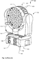
- Figure 1a-1b illustrates an illumination device according to prior art, where fig. 1a is a perspective view and fig 1b is an exploded view.
- the illumination device is a moving head lighting fixture 101 comprising a base 103, a yoke 105 rotatable connected to the base and a head rotatable connected 107 to the yoke.
- the head comprises a number of light sources and a number of light collecting means 109 arranged in the head housing 111.
- the light collecting means collect light from at the light sources and convert the collected light into a number of source light beams 113 (only one illustrated), which are emitted from the housing.
- the head housing 107 is a "bucket" shaped head housing 111 wherein a display 115 (visible from the rear side of the head), main PCB 117 (Printed Circuit Board), a fan 119, a heat sink 121, an LED PCB 123, and lens assembly are stacked.
- the lens assembly comprises a lens holder 125 and a lens array comprising the light collecting means 109.
- the head is rotatable connected to the yoke by two tilt bearings 127 and which are supported by the yoke 105.
- a tilt motor 129 is adapted to rotate the head through a tilt belt 131 connected to one of the tilt bearings 127.
- the yoke comprises two interlocked yoke shell parts 132 which are mounted to a yoke frame 134 where on the tilt bearings, tilt motor, pan motor and pan bearing are arranged.
- the LED PCB 123 comprises a number of LEDs emitting light and which in cooperation with the light collecting means 109 in the lens array generate a number of light source beams.
- the main PCB comprises controlling circuits and driving circuits (not shown) for controlling the LEDs as known in the art of illumination devices.
- the main PCB comprises further a number of switches (not shown) which extend through a number of holes in the head housing 111. The switches and display act as a user interface allowing a user to communicate with the moving head lighting fixture.
- the yoke are connected to a pan bearing 133 rotatable connected to the base 103.
- a pan motor 135 is adapted to rotate the yoke through a pan belt 137 connected to the pan bearing 133.
- the base comprises 5-Pin XLR male 139 and female 141 connectors for DMX signals as known in the art of entertainment lighting; input 143 and output power 145 connectors, power supply PCB's (not shown) and fan (not shown). The fan forces air into the base through vent holes 147.
- This prior art illumination device uses multiple LEDs to replace a single light source as known prior the introduction of the LED component as a widely used light source.
- Such illumination device changes its visible appearance as the multiple light sources are now exposed to the viewer and the light emits from a larger area. If the light luminaries are a color mixing version with single color LEDs, then all LED colors used are visible. However some customers dislike the look of multiple light dots. Instead a more uniform, even light exit is requested, to avoid the cheap looking "funfair" look with an extreme amount of light sources.
- the illuminating device illustrated in fig. 1a and 1b is just one example of a prior art illumination derive and the skilled person realize that a large number of different embodiments provided by a large number of manufactures exits.
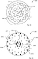
- Figures 2a-d illustrate a simplified embodiment of an illumination device according to the present invention.
- Fig. 2a is a top view and fig. 2b is a top view with the light guide 213 and light collecting means 209 removed.
- Fig. 2c and 2b is cross sectional views along line A-A and B-B respectively.
- the illumination device 201 comprises a number of light sources arranged in at least a first group of light sources 203 (indicated as white quadrangles) and in a second group of light sources 205 (indicated as black quadrangles).
- the light sources are mounted on a PCB 207 (printed circuit board) and the two groups of light sources can be controlled individually for instance by a controller (not shown) as known in the art of lighting.
- the controller is thus adapted to treat the two groups of light sources as at least two individual light sources which can be individually controlled.
- the illumination device also can be adapted to divide each group of light sources into a number of sub-groups which also can be controlled individual and that it is also possible to control each single light source individually.
- a number of light collecting means 209 are arrange above and around the first group light sources 203 and is adapted to collect light from the first group of light sources and convert the collected light into a number of source light beams 211.
- the light collecting means 209 can be embodied as any optical component capable of collecting light from the light sources and convert the light into light beams and can for instance be optical lenses, light mixers, TIR lenses etc.
- the light collecting means 209 are embodied as TIR lenses as known in the prior art and the skilled person realizes that the TIR lens can be designed according the light output of the light source and the descried optical properties of the source light beam 211.
- a light guide 213 is arranged above the PCB 207 and the light guide 213 comprises an input section 217 and an output section 219.
- the light guide receives light from the second group of light sources 205 at the input section 217 and guides the received light to the output section 219, which is adapted to emit the received light at an area 218 between at least two of the source light beams 211.
- the light beams 211 will merge into one large light beams as the distance to the illumination device increases.
- the area between at least two light source beam can be defined as all points which seen from above the light source beams lie on a straight line that intercepts at least a part of both light beams.
- the light guide 213 is embodied as a solid transparent material and light rays entering an input section will be internally reflected to an output section where the light rays is coupled out of the light guide.
- the light guide 213 is form as a light guide disc comprising a number of openings wherein the light collecting means are arranged and a number of protrusions 220 protruding backward from the light guide disc.
- the protrusions are adapted to fit above the light sources 205 of the second group and the input sections are situated at the bottom surface of the protrusions.
- the output sections constitute the front area of the light guide disc. The light entering the input sections is firstly internally reflected through the protrusions and is then reflected at angled reflection surfaces 222 in a direction substantially along the plane of the disc.
- the light source 205a belonging to the second group of light sources emits a number of light rays (illustrated as thin solid lines).
- the light rays enter the light guide 213 at input section 217a where after they experience internal reflection inside the light guide and are hereby guided to the output section 219a where the light rays are coupled out of the light guide 213.
- the output section 219a where the light rays are coupled out of the light guide 213.
- the light source 205b belonging to the second group of light sources emits a number of light rays (illustrated as thin solid lines) which enter the light guide 213 at input section 217b and is coupled out of the light guide 213 at output section 219b.
- light sources 205c and 205d generates light beams which is emitted from output sections 219c and 219d respectively. The result is that the areas between the light beams can be illuminated by the second group of light sources 205 and the dotted look the prior art light fixtures can be avoided.
- the output sections 219 are adapted to couple the light rays out of the light guide. This can for instance be achieved by adjusting the roughness of the surface of the light guide at the output sections whereby the light rays does not experience total internal reflection when they hit the rough surface and as consequences the light is coupled out of the light guide.
- the surface of the light guide 213 can be treated with a material which will scatter the light hitting the output section. Another opportunity is to angle to bottom and top surface of the light guide relatively to each other, which results the fact the incident angle of the light rays traveling inside the light guide will change.
- the output sections can be adapted to couple the light out of the light guide in a homogenized way such that the entire front surface of the light guide disc appears as one homogeneous illuminating surface.
- the light guide and out coupling can for instance be constructed using techniques known in the art of background lighting from TV displays and/or mobile phone displays.
- the light guide is shaped as a disc however it is be understood that the light guide can have any shape.
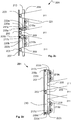
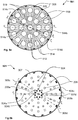
- Figures 3a-3d illustrate another embodiment of an illumination device according to the present invention.
- Fig. 3a is a top view and fig. 3b is a top view with the light guide 313 and light collecting means 209 removed.
- Fig. 3c and 3d is cross sectional views along line C-C and D-D respectively.
- the first group of light sources 203 (indicated as white quadrangles) is arrange on a PCB 207 with the light colleting means 209 arranged above the light sources and a number of source light beams 211 are hereby created.
- at part of the light sources of the second group 205 are mounted on the PCB 207 as in fig. 2a-2d .
- the light source 205a and 205b emits a number of light rays (illustrated as thin solid lines) which enter the light guide 313 respectively at input section 217a and 217b and is coupled out of the light guide 313 at output sections 219a and 219b.
- another part 305 of the second group light sources are arrange circumferentially around the light guide 313 and mounted on a number of upstanding PCBs 308 which are perpendicularly in relation to PCB 207. The consequence it that the circumferential wall of the light guide 313 can act as input sector 317.
- the source 305c and 305d emit a number of light rays (illustrated as thin solid lines) which enter the light guide 313 respectively at input section 317cand 317d and is coupled out of the light guide 313 at output sections 319c and 319d.
- the inner ring of light sources also can be adapted to emit light directly into the light guide for instance by arranging these light sources around the center light collecting means and letting the light sources emit light outwardly in relation the center of the light guide.
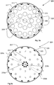
- Fig. 4 illustrates an embodiment which is similar to the embodiment in fig 3a-3d , however the light guide 413 have been modified, such that the output sections 417 have been arrange in a predetermined pattern and light will thus only exit the light guide at these areas.
- the second group of light sources can be used to create an optical pattern between the light beams and this optical pattern can be used to create light effects which can be observed by a spectator looking at the illumination device.
- the light sources can be arranged such light from one or a sub-group of light sources illuminated a specific output section and the illumination device can be adapted to control the sub-groups individually. This makes it possible to control different part of the optical pattern individually for instance by turning on/off, changing color certain parts of the predertertmined pattern.
- the predetermined pattern can in this way be used as a dynamic pattern which can be used to crate several of interesting light effects.
- the predetermined pattern of the light guide 413 can for instance be created by treating the upper surface of the light guide in predetermined pattern such that light is only coupled out of the light guide at these areas while the light rays experience internal reflection at the other areas. It also possible to achieve the same effect by using a multiple number of light guides which acts as individual light guides (for instance as illustrated in fig. 6a and 6b ) rather than being integrated as one light guide disc.
- Figures 5a-5e illustrates another embodiment of an illumination device according to the present invention.
- Fig. 5a is a top view and fig. 5b is a top view with the light guides 513, collecting means 209 removed and diffuser regions 512 removed.
- Fig. 5c, 5d and 5e is cross sectional views along line E-E, F-F and G-G respectively.
- the first group of light sources 203 (indicated as white quadrangles) is arrange on a PCB 207 with the light colleting means 209 arranged above the light sources and a number of source light beams 211 are hereby created.
- a part of the light sources of the second group 205 (illustrated in black quadrangles) are mounted on the PCB 207 while another part 305 of the second group light sources are arranged on number of upstanding PCBs 308 which are perpendicularly in relation to PCB 207.
- a number of light guides 514 (illustrated in detailing in fig. 6a and 6b ) comprising an input section and output section is arranged above the PCB 207.
- the light guides 514 is adapted to receive light from at least one the second group light sources at the input section and to guide the received light to the output section 519, which is adapted to emit the received light at an area between at least two of the source light beams 211.
- the illumination device comprises a third group of light sources 504 (illustrated as cross-hatched quadrangles) arranged on the PCB 207 and a number of diffuser regions 512 arranged above the PCB 207 and between at least two light source beam.
- the diffuser regions 514 is adapted to receive light from at least one of the light sources of the third group of light sources and to diffuse the received light.
- light source 205a and 205b emits a number of light rays (illustrated as thin solid lines) which respectively enters light guide 514a and 514b at input sections 517a and 517b and is coupled out of the light guide 514a and 514b at output sections 519a and 519b.
- the source 305c and 305d emit a number of light rays (illustrated as thin solid lines) which respectively enter the light guide 514c and 514d at input section 517c and 517d and is coupled out of the light guides at output sections 519c and 519d.
- 5e light sources 504a-d will illuminate the diffraction regions 512a-d and the light from these light sources will be diffused into many directions as illustrated by arrows 516a-516d.
- the consequence is that the dotted look of an illumination device as known in the prior art can be avoided and the illumination device can at the same time be used to crated graphical light effects by controlling the second group of light sources.
- the diffuser regions can for instance be embodied as one single solid body of a transparent material, which is adapted to diffuse light hitting the solid body. For instance by molding the solid body in transparent polymer and treating the surfaces such that they will diffuse light.
- the solid body can be contracted with a number of holes were in the light collecting means 209 and light guides 514 can be arranged.
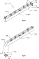
- Fig 6a and fig. 6b respectively illustrated the two types light guides used in fig 5a-5e .
- the light guide in fig. 6a correspond the light guides 514 (for instance 514c and 514d of fig. 5a-e ) which are adapted to receive light form the light sources 305 arranged circumferentially around the PCB 207.
- the light guide is constructed of a transparent rod 601 comprising an input section 602 and an output section 603.
- the output section constitutes one surface of the rod and has been treated such that the light will be coupled out of this surface as illustrated by arrows 605.
- the light source 305 is a 4 in 1 LED light source comprising a red die R, Green die G, blue die B and white die W and can thus create a large amount of different color by using additive color mixing.
- the light rod assists also in mixing the colors from the 4 LED dies.
- the light guide in fig. 6b correspond the light guides 514 (for instance 514a and 514b of fig. 5a-e ) which are adapted to receive light form the light sources 205 on the PCB 207.
- This light guide comprises a bend 606 which is adapted to reflect light coming from the input section towards the output section 603.
- Fig. 7 illustrates a block diagram of the illumination device according the present invention.
- the illumination device comprises a control unit 701 comprising a processor 703 and a memory 705.
- the first group of light sources 203 and the second group of light sources 205 is connected to the control unit 701 and is arranged according to the present invention.
- the processor acts as controlling means and is adapted to control the first group 203 of light sources and the second group 205 of light sources individually. Meaning the processing means can control one of the groups of light sources without controlling the other group of light sources.
- the controlling can for instance adapted to control the color and/or intensity of the light sources and can be based on any type of communication signals known in the art of lightning e.g. PWM, AM, FM, binary signals etc.
- the first 203 and second 205 group of light sources array can thus be controlled individually and independently of each other can thus be treated as two individually and independently groups of light sources. It is to be understood that the individually light sources of each groups be controlled by the same control signal, supplied with individual control signals and/or grouped in subgroups where each subgroup receive the same control signal.
- the controlling means is adapted to control said first group of light sources based on an input signal indicative of a first target color of said first group of light sources.
- the input signal can be any signal capable of communication parameters and can for instance be based on one of the following protocols USITT DMX 512, USITT DMX 512 1990, USITT DMX 512-A, DMX-512-A including RDM as covered by ANSI E1.11 and ANSI E1.20 standards or Wireless DMX.
- ACN designates Architecture for Control Networks; ANSI E1.17 - 2006).
- the input signal can for instance be indicative of a first target color can be any parameter defining the color of the light that the first group light sources shall generate, for instance RGB values, color coordinates in color maps etc.
- the controlling means can be adapted to control the second group of light sources based on the input signal indicative of the first target color of whereby the second group of light sources can be adapted generate substantial the same color as the color generated by the first group of light sources.
- a color scheme such that the color of the second array is adjusted such that the color of the second group of light sources is different but esthetic matches each other according to a predetermined color scheme.
- the input signal can also be indicative of a second target color and the color of the second group of light sources can be controlled based on this second target color parameter.
- the illumination device also can comprise a third group 504 of light sources as illustrated in connection with fig. 5a-e .
- This group can be controlled in similar manners as the two other groups of light sources.
- the second and third group of light sources can functions as background lighting with own DMX control and both color and intensity can be varied independently of the first group of light sources. They can also be intensity and color linked with primary LED color in a predetermined manner or has separate control for contrast colors or other intensity. This adjustment/control of the light sources can be done remotely from central control unit or at the fixture itself. The consequence is that a new light effect can be created as the area between the light beams can have another color emitted by the second group of light sources. This look can by dynamic if first group of light sources and the second group of light sources are independently controlled as known in the art of entertainment lighting.
Claims (16)
- Dispositif d'éclairage (201) comprenant :• un certain nombre de sources de lumière agencées dans au moins un premier groupe de sources de lumière (203) et dans un deuxième groupe de sources de lumière (205), dans lequel ledit premier groupe de sources de lumière et ledit deuxième groupe de sources de lumière peuvent être commandés individuellement ;• un certain nombre de moyens de collecte de lumière (209), ledit nombre de moyens de collecte de lumière (209) collectent la lumière dudit premier groupe de sources de lumière et convertissent ladite lumière collectée en un certain nombre de faisceaux lumineux source (211) ;• au moins un guide de lumière (213) comprenant une section d'entrée (217) et une section de sortie, ledit guide de lumière reçoit la lumière générée par ledit deuxième groupe de sources de lumière (205) au niveau de ladite section d'entrée (217) et transfère ladite lumière reçue vers ladite section de sortie, ladite section de sortie étant adaptée pour émettre ladite lumière reçue au niveau d'une zone entre au moins deux desdits faisceaux lumineux source ; dans lequel ledit guide de lumière est formé en tant que disque de guidage de lumière, caractérisé en ce que le disque de guidage de lumière comprend un certain nombre d'ouvertures dans lequel les moyens de collecte de lumière (209) sont agencés ; et dans lequel une zone avant du disque de guidage de lumière comprend ladite section de sortie et ladite section de sortie est adaptée pour diffuser ladite lumière émise dans de nombreuses directions.
- Dispositif d'éclairage (201) selon la revendication 1 ; dans lequel un certain nombre de saillies font saillie vers l'arrière du disque de guidage de lumière ; la lumière entrant dans la section d'entrée (217) est d'abord réfléchie à l'intérieur par les saillies et est ensuite réfléchie à des surfaces de réflexion inclinées dans une direction sensiblement le long du plan du disque.
- Dispositif d'éclairage (201) selon la revendication 2 ; dans lequel les saillies sont adaptées pour s'ajuster au-dessus du deuxième groupe de sources de lumière (205) et la section d'entrée (217) est située au niveau de la surface inférieure des saillies.
- Dispositif d'éclairage (201) selon les revendications 1-3 caractérisé en ce que ledit dispositif d'éclairage comprend des moyens de commande adaptés pour commander individuellement ledit premier groupe de sources de lumière (205) et ledit deuxième groupe de sources de lumière.
- Dispositif d'éclairage (201) selon la revendication 4 caractérisé en ce que ledit moyen de commande est adapté pour commander ledit premier groupe de sources de lumière (205) sur la base d'un signal d'entrée indiquant une première couleur cible.
- Dispositif d'éclairage (201) selon la revendication 5 caractérisé en ce que lesdits moyens de commande sont adaptés pour commander ledit deuxième groupe de sources de lumière (205) sur la base de ladite première couleur cible.
- Dispositif d'éclairage (201) selon les revendications 4-5 caractérisé en ce que ledit signal d'entrée indique en outre une deuxième couleur cible et en ce que lesdits moyens de commande sont adaptés pour commander ledit deuxième groupe de sources de lumière (205) sur la base de ladite deuxième couleur cible.
- Dispositif d'éclairage (201) selon les revendications 1-7 caractérisé en ce que lesdits secteurs de sortie et lesdites sources de lumière (205) dudit deuxième groupe de sources de lumière (205) sont agencés selon un motif prédéterminé, de sorte que chacun desdits secteurs de sortie émette de la lumière d'au moins une desdites sources de lumière dudit deuxième groupe et en ce que lesdits moyens de commande sont adaptés pour commander lesdites sources de lumière éclairant chaque secteur de sortie individuellement
- Dispositif d'éclairage (201) selon les revendications 1-8 caractérisé en ce que ledit nombre de sources de lumière (205) est agencé en outre dans un troisième groupe de source de lumière et en ce que ledit dispositif d'éclairage comprend en outre au moins une région de diffuseur agencée entre au moins deux desdits faisceaux lumineux de source, ladite région de diffuseur reçoit et diffuse la lumière générée par ledit troisième groupe de sources de lumière.
- Luminaire à tête mobile comprenant :∘ une base (103),∘ un étrier (105) relié de manière rotative à ladite base,∘ une tête reliée audit étrier rotatif (105),caractérisé en ce que ladite tête comprend un dispositif d'éclairage (201) selon les revendications 1-9.
- Procédé de commande d'un dispositif d'éclairage (201) comprenant les étapes de :• agencement d'un certain nombre de sources de lumière dans au moins un premier groupe de sources de lumière et dans un deuxième groupe de sources de lumière ;• création d'un certain nombre de faisceaux de source de lumière par adaptation d'un certain nombre de moyens de collecte de lumière (209) pour collecter la lumière dudit premier groupe de sources de lumière et pour convertir ladite lumière collectée dans ledit nombre de faisceaux lumineux source ;• guidage de la lumière générée par ledit deuxième groupe de sources de lumière vers une zone entre au moins deux desdits faisceaux lumineux source en utilisant un guide de lumière (213) ; dans lequel ledit guide de lumière (213) est formé en tant que disque de guidage de lumière, comprenant un certain nombre d'ouvertures dans lequel les moyens de collecte de lumière (209) sont agencés ; et dans lequel une zone avant du disque de guidage de lumière comprend ladite section de sortie et ladite section de sortie est adaptée pour diffuser ladite lumière émise dans de nombreuses directions.
- Procédé selon la revendication 11 caractérisé en ce que ladite étape de guidage de lumière guidant la lumière générée par ledit deuxième groupe de sources de lumière vers une zone entre au moins deux desdits faisceaux lumineux source en utilisant un guide de lumière (213) comprend les étapes de :• émission de lumière dans ledit guide de lumière (213) par une section d'entrée ;• transfert de ladite lumière vers une section de sortie, ladite section de sortie étant positionnée entre au moins deux desdits faisceaux lumineux source ;• couplage de ladite lumière hors dudit guide de lumière (213) à travers ladite section de sortie.
- Procédé selon les revendications 11-12 caractérisé en ce que ledit procédé comprend les étapes de :• commande dudit premier groupe de sources de lumière sur la base d'une première couleur cible ;• commande dudit deuxième groupe de sources de lumière sur une deuxième couleur cible.
- Procédé selon les revendications 11-13 caractérisé en ce que ledit procédé comprend l'étape de :• agencement dudit nombre de sources de lumière agencées dans un troisième groupe de sources de lumière ;• éclairage d'une zone entre au moins deux desdits faisceaux de source de lumière par fourniture de moyens de diffusion entre au moins deux desdits faisceaux de source de lumière et par adaptation desdites moyens de diffusion pour recevoir la lumière générée par ledit troisième groupe de sources de lumière et diffuser ladite lumière reçue.
- Procédé selon les revendications 14 caractérisé en ce que ledit procédé comprend les étapes de :• commande dudit troisième groupe de sources de lumière sur la base d'une troisième couleur cible.
- Procédé selon la revendication 15 caractérisé en ce que ledit procédé comprend les étapes de :• détermination d'au moins ladite deuxième couleur cible ou d'au moins ladite troisième couleur cible sur la base de ladite première couleur cible.
Applications Claiming Priority (4)
| Application Number | Priority Date | Filing Date | Title |
|---|---|---|---|
| DKPA201000361A DK177579B1 (en) | 2010-04-23 | 2010-04-23 | Led light fixture with background lighting |
| EP15183887.7A EP2988064B1 (fr) | 2010-04-23 | 2011-04-05 | Luminaire à del avec retroéclairage |
| PCT/DK2011/050112 WO2011131199A1 (fr) | 2010-04-23 | 2011-04-05 | Luminaire à diodes électroluminescentes à effets de rétroéclairage muni de secondes sources de lumière à lumière guidée |
| EP11771616.7A EP2561274B1 (fr) | 2010-04-23 | 2011-04-05 | Luminaire à diodes électroluminescentes à effets de rétroéclairage muni de secondes sources de lumière à lumière guidée |
Related Parent Applications (2)
| Application Number | Title | Priority Date | Filing Date |
|---|---|---|---|
| EP15183887.7A Division EP2988064B1 (fr) | 2010-04-23 | 2011-04-05 | Luminaire à del avec retroéclairage |
| EP11771616.7A Division EP2561274B1 (fr) | 2010-04-23 | 2011-04-05 | Luminaire à diodes électroluminescentes à effets de rétroéclairage muni de secondes sources de lumière à lumière guidée |
Publications (2)
| Publication Number | Publication Date |
|---|---|
| EP3343103A1 EP3343103A1 (fr) | 2018-07-04 |
| EP3343103B1 true EP3343103B1 (fr) | 2019-08-07 |
Family
ID=44833737
Family Applications (4)
| Application Number | Title | Priority Date | Filing Date |
|---|---|---|---|
| EP11771614.2A Active EP2561272B1 (fr) | 2010-04-23 | 2011-04-05 | Luminaire à diodes électroluminescentes à rétroéclairage utilisant un groupe de lumières diffuses intermédiaire commandé |
| EP11771616.7A Active EP2561274B1 (fr) | 2010-04-23 | 2011-04-05 | Luminaire à diodes électroluminescentes à effets de rétroéclairage muni de secondes sources de lumière à lumière guidée |
| EP15183887.7A Active EP2988064B1 (fr) | 2010-04-23 | 2011-04-05 | Luminaire à del avec retroéclairage |
| EP18156524.3A Active EP3343103B1 (fr) | 2010-04-23 | 2011-04-05 | Luminaire à del comportant des effets de lumière d'arrière-plan |
Family Applications Before (3)
| Application Number | Title | Priority Date | Filing Date |
|---|---|---|---|
| EP11771614.2A Active EP2561272B1 (fr) | 2010-04-23 | 2011-04-05 | Luminaire à diodes électroluminescentes à rétroéclairage utilisant un groupe de lumières diffuses intermédiaire commandé |
| EP11771616.7A Active EP2561274B1 (fr) | 2010-04-23 | 2011-04-05 | Luminaire à diodes électroluminescentes à effets de rétroéclairage muni de secondes sources de lumière à lumière guidée |
| EP15183887.7A Active EP2988064B1 (fr) | 2010-04-23 | 2011-04-05 | Luminaire à del avec retroéclairage |
Country Status (8)
| Country | Link |
|---|---|
| US (3) | US9144120B2 (fr) |
| EP (4) | EP2561272B1 (fr) |
| JP (3) | JP5587494B2 (fr) |
| CN (3) | CN102859269B (fr) |
| BR (2) | BR112012027038B1 (fr) |
| DK (2) | DK177579B1 (fr) |
| RU (2) | RU2539316C2 (fr) |
| WO (2) | WO2011131197A1 (fr) |
Families Citing this family (71)
| Publication number | Priority date | Publication date | Assignee | Title |
|---|---|---|---|---|
| US9562672B2 (en) | 2011-10-23 | 2017-02-07 | Martin Professional A/S | Illumination device with multi-colored light beam |
| US10663652B2 (en) * | 2011-12-30 | 2020-05-26 | Fraen Corporation | Light mixing systems with a glass light pipe |
| KR20140136427A (ko) | 2011-12-30 | 2014-11-28 | 프라엔 코퍼레이션 에스.알.엘. | 광 혼합 렌즈들 및 시스템들 |
| US9995872B2 (en) | 2011-12-30 | 2018-06-12 | Fraen Corporation | Light mixing systems with a glass light pipe |
| DK177371B1 (en) * | 2012-02-14 | 2013-02-25 | Martin Professional As | Animation and gobo forming means for illumination device |
| EP2828573B1 (fr) * | 2012-03-18 | 2017-05-10 | Robe Lighting, Inc | Système de collimation amélioré pour luminaire à del |
| ES1077248Y (es) * | 2012-06-05 | 2012-09-17 | Antares Iluminacion Sa | Dispositivo proyector de luz |
| TWM441214U (en) * | 2012-06-07 | 2012-11-11 | Lextar Electronics Corp | Light source module |
| JP6192279B2 (ja) * | 2012-06-08 | 2017-09-06 | 日立アプライアンス株式会社 | 照明装置 |
| US9927079B2 (en) | 2012-09-11 | 2018-03-27 | Abl Ip Holding Llc | Recessed luminaire |
| KR101284156B1 (ko) * | 2012-12-11 | 2013-07-10 | 고인홍 | 독자적으로 점소등되는 led어레이들을 갖는 led 조명장치 |
| US9851072B2 (en) * | 2013-04-09 | 2017-12-26 | Philips Lighting Holding B.V. | Arrangement for changing the visual appearance of a target object |
| DK3004732T3 (da) * | 2013-06-07 | 2022-09-12 | Harman Professional Denmark Aps | Led-pixel-enhed med dynamiske lysspredervirkninger |
| ITMI20131386A1 (it) * | 2013-08-12 | 2015-02-13 | Clay Paky Spa | Proiettore da palcoscenico |
| WO2015033296A1 (fr) | 2013-09-09 | 2015-03-12 | Koninklijke Philips N.V. | Luminaire à motif d'émission sélectionnable |
| US9995463B2 (en) | 2013-10-05 | 2018-06-12 | Martin Professional Aps | Illumination device with spinning zoom lens |
| US10873998B2 (en) * | 2013-11-20 | 2020-12-22 | Signify Holding B.V. | Methods and apparatus for controlling illumination of a multiple light source lighting unit |
| CN103851525B (zh) * | 2014-02-23 | 2016-02-24 | 中山市蓝河光电照明科技有限公司 | 一种多功能车用灯 |
| CN104930425A (zh) * | 2014-03-19 | 2015-09-23 | 深圳市海洋王照明工程有限公司 | 一种机车灯 |
| CN104930427A (zh) * | 2014-03-19 | 2015-09-23 | 深圳市海洋王照明工程有限公司 | 矿用led机车灯 |
| US9549441B2 (en) * | 2014-03-20 | 2017-01-17 | The Boeing Company | Lighting device to simulate natural motion |
| DE202014102004U1 (de) * | 2014-04-29 | 2015-07-31 | Zumtobel Lighting Gmbh | Anordnung zur Lichtabgabe für die Raumbeleuchtung |
| EP2955430B1 (fr) | 2014-06-12 | 2019-07-31 | Harman Professional Denmark ApS | Dispositif d'éclairage avec des faisceaux de lumière uniforme |
| USD744156S1 (en) * | 2014-06-25 | 2015-11-24 | Martin Professional Aps | Light lens |
| EP2993393B1 (fr) * | 2014-09-03 | 2018-08-22 | Vignal C.E.A. S.A. | Appareil d'éclairage |
| US10718474B1 (en) | 2014-11-20 | 2020-07-21 | The Light Source, Inc. | Lighting fixture with closely-packed LED components |
| CN104748010B (zh) * | 2015-03-19 | 2017-11-17 | 佛山市百特思舞台设备有限公司 | 一种led灯光投射方法与所用灯光投射装置 |
| FR3041077B1 (fr) * | 2015-09-15 | 2018-09-07 | Valeo Vision | Dispositif lumineux, notamment pour vehicule automobile et projecteur comprenant un tel dispositif. |
| US10962209B2 (en) | 2015-12-15 | 2021-03-30 | Wangs Alliance Corporation | LED lighting methods and apparatus |
| US11686459B2 (en) | 2015-12-15 | 2023-06-27 | Wangs Alliance Corporation | LED lighting methods and apparatus |
| GB201602029D0 (en) * | 2016-02-04 | 2016-03-23 | Aurora Ltd | Horticultural lighting device |
| US10359184B2 (en) * | 2016-02-05 | 2019-07-23 | Timothy Lee Anderson | Laser based visual effect device and system |
| US10132992B2 (en) | 2016-03-20 | 2018-11-20 | Robe Lighting S.R.O. | Special flower effects beam and washlight luminaire |
| CN109312902B (zh) * | 2016-04-01 | 2020-10-20 | 罗布照明公司 | 具有特殊效果功能的染色光照明装置 |
| CN107435882B (zh) * | 2016-05-27 | 2020-11-03 | 小丝电工株式会社 | 照明装置 |
| US10086751B2 (en) * | 2016-06-24 | 2018-10-02 | Ford Global Technologies, Llc | Vehicle lighting system having a spotlight |
| US10352539B2 (en) * | 2016-10-24 | 2019-07-16 | Chauvet & Sons, Llc | Yoke effect multi-beam lighting device and system |
| IT201700022288A1 (it) * | 2017-02-28 | 2018-08-28 | Innovation Green Tech S R L | Dispositivo di illuminazione per la crescita delle piante |
| FR3063335B1 (fr) * | 2017-02-28 | 2021-07-02 | Valeo Vision | Dispositif lumineux pour vehicule automobile comprenant une source de lumiere comportant une pluralite d'elements emissifs |
| BR112019018693A2 (pt) * | 2017-03-10 | 2020-04-07 | Roland Kohen Ran | dispositivo de conexão rápida para instalações elétricas embutidas |
| EP3392556B1 (fr) * | 2017-04-19 | 2020-12-16 | Harman Professional Denmark ApS | Dispositif d'éclairage multisourceur avec dimmer variable |
| JP6249430B1 (ja) * | 2017-05-16 | 2017-12-20 | 株式会社佐藤工業所 | 照明装置 |
| US11812525B2 (en) * | 2017-06-27 | 2023-11-07 | Wangs Alliance Corporation | Methods and apparatus for controlling the current supplied to light emitting diodes |
| DE102017211141A1 (de) * | 2017-06-30 | 2019-01-03 | Osram Gmbh | Effektleuchte, leuchtengruppe, anordnung und verfahren |
| RU2672258C1 (ru) * | 2017-07-21 | 2018-11-13 | Юрий Афанасьевич Зыкин | Сигнально-осветительный фонарь |
| TWI625489B (zh) * | 2017-07-21 | 2018-06-01 | 久鐵工業股份有限公司 | 複合式燈具 |
| BE1025429B1 (fr) * | 2017-07-24 | 2019-02-21 | Schreder Sa | Système d’éclairage à distribution lumineuse réglable |
| CN108019628B (zh) * | 2017-11-06 | 2019-07-30 | 宁波凯耀电器制造有限公司 | 设旋转片的led灯及其装配方法 |
| CN108036242A (zh) * | 2018-01-16 | 2018-05-15 | 佛山市百特思舞台设备有限公司 | 一种文物艺术品展陈的照明装置及其照明方法 |
| USD866028S1 (en) | 2018-04-17 | 2019-11-05 | Black & Decker Inc. | Area light |
| US10585292B2 (en) | 2018-06-28 | 2020-03-10 | Fraen Corporation | Low-profile color-mixing lightpipe |
| USD943794S1 (en) * | 2018-10-29 | 2022-02-15 | Event Concept Limited | Lamp |
| USD951511S1 (en) * | 2018-10-29 | 2022-05-10 | Event Concept Limited | Lamp |
| USD921256S1 (en) * | 2018-11-28 | 2021-06-01 | Shenzhen Huadian Lighting Co., Ltd. | LED stadium light |
| WO2020151984A1 (fr) | 2019-01-21 | 2020-07-30 | Lumileds Holding B.V. | Système d'éclairage avec élément de motif |
| WO2020212464A1 (fr) * | 2019-04-18 | 2020-10-22 | Signify Holding B.V. | Dispositif d'illumination, système d'éclairage et procédé destiné à commander le dispositif d'illumination |
| US20220225487A1 (en) * | 2019-04-18 | 2022-07-14 | Signify Holding B.V. | Sparkle spot light |
| US10551034B1 (en) | 2019-05-15 | 2020-02-04 | Richard S. Belliveau | Multicell theatrical light incorporating a plurality of diffuse aureoles |
| US11598517B2 (en) | 2019-12-31 | 2023-03-07 | Lumien Enterprise, Inc. | Electronic module group |
| CN110985903B (zh) | 2019-12-31 | 2020-08-14 | 江苏舒适照明有限公司 | 一种灯模组 |
| KR20210117726A (ko) * | 2020-03-20 | 2021-09-29 | 엘지이노텍 주식회사 | 조명모듈 및 조명장치 |
| CN111503556B (zh) | 2020-04-23 | 2020-11-27 | 江苏舒适照明有限公司 | 一种射灯结构 |
| EP4163907A4 (fr) | 2020-06-05 | 2023-08-30 | Guangzhou Haoyang Electronic Co., Ltd. | Écran d'affichage de forme unique, lampe à pixels de forme unique, et procédé de commande pour lampe à pixels de forme unique |
| CN113838384B (zh) * | 2020-06-05 | 2023-03-21 | 广州市浩洋电子股份有限公司 | 一种异形显示屏、异形像素灯及异形像素灯的控制方法 |
| US11181251B1 (en) * | 2020-10-19 | 2021-11-23 | Xiamen Leedarson Lighting Co., Ltd | Lighting apparatus |
| DE102020127949A1 (de) * | 2020-10-23 | 2022-04-28 | Helge Hoffmann | Scheinwerfersystem und Scheinwerfer |
| CN112558383B (zh) * | 2021-01-05 | 2022-02-01 | 深圳市本特利科技有限公司 | 一种用于水下目标探测变焦照明设备 |
| EP4080112A1 (fr) | 2021-04-22 | 2022-10-26 | Harman Professional Denmark ApS | Dispositif d'éclairage doté d'un effet d'émulation de source de lumière |
| US11812532B2 (en) | 2021-05-27 | 2023-11-07 | Wangs Alliance Corporation | Multiplexed segmented lighting lamina |
| US11767964B2 (en) | 2021-11-15 | 2023-09-26 | Robe Lighting S.R.O. | Homogenization of an LED array |
| US11802682B1 (en) | 2022-08-29 | 2023-10-31 | Wangs Alliance Corporation | Modular articulating lighting |
Family Cites Families (81)
| Publication number | Priority date | Publication date | Assignee | Title |
|---|---|---|---|---|
| GB818164A (en) | 1955-08-19 | 1959-08-12 | Paul Guenther Erbsloeh | Improvements in headlamps |
| SU1682716A1 (ru) * | 1989-04-11 | 1991-10-07 | И.А. Коробченко | Декоративный светильник |
| RU2006737C1 (ru) * | 1990-05-30 | 1994-01-30 | Юлия Алексеевна Щепочкина | Осветительное устройство |
| SU1756737A1 (ru) * | 1990-10-29 | 1992-08-23 | Государственный оптический институт им.С.И.Вавилова | Декоративный светильник |
| RU2037084C1 (ru) * | 1992-12-22 | 1995-06-09 | Сысун Виктор Викторович | Прожектор |
| US5816681A (en) * | 1995-11-02 | 1998-10-06 | Kaiser Optical Systems, Inc. | Inconspicuous light sources particularly for vehicular applications |
| US5803579A (en) * | 1996-06-13 | 1998-09-08 | Gentex Corporation | Illuminator assembly incorporating light emitting diodes |
| US7352339B2 (en) * | 1997-08-26 | 2008-04-01 | Philips Solid-State Lighting Solutions | Diffuse illumination systems and methods |
| US6016038A (en) * | 1997-08-26 | 2000-01-18 | Color Kinetics, Inc. | Multicolored LED lighting method and apparatus |
| US6969960B2 (en) * | 1999-09-10 | 2005-11-29 | Belliveau Richard S | Image projection lighting device |
| JP2002208492A (ja) * | 2001-01-11 | 2002-07-26 | Almex Inc | サーチライトを使用した夜間照明システム |
| US7077525B2 (en) * | 2001-02-06 | 2006-07-18 | Optics 1, Inc | Led-based flashlight |
| US6749310B2 (en) * | 2001-09-07 | 2004-06-15 | Contrast Lighting Services, Inc. | Wide area lighting effects system |
| US7358929B2 (en) * | 2001-09-17 | 2008-04-15 | Philips Solid-State Lighting Solutions, Inc. | Tile lighting methods and systems |
| JP2003245392A (ja) * | 2002-02-22 | 2003-09-02 | Asahi Matsushita Electric Works Ltd | 照明装置 |
| DE10210780A1 (de) | 2002-03-12 | 2004-04-08 | Hella Kg Hueck & Co. | Innenleuchte für Fahrzeuge mit einer Streuscheibe |
| US6802612B2 (en) * | 2002-03-15 | 2004-10-12 | Hewlett-Packard Development Company, L.P. | Configurations for color displays by the use of lenticular optics |
| US20030231489A1 (en) * | 2002-06-18 | 2003-12-18 | Yu-Teng Hsiao | Coupling system for securing an illuminating light to a cap visor |
| JP3989412B2 (ja) * | 2002-10-21 | 2007-10-10 | オリンパス株式会社 | 照明装置及び画像投影装置 |
| JP2004141240A (ja) * | 2002-10-22 | 2004-05-20 | Fuji Photo Film Co Ltd | 放射線検出用カセッテおよび画像情報管理システム |
| US6802622B2 (en) * | 2002-11-15 | 2004-10-12 | Chih-Ching Hsien | Flashlight with convex lens assembly providing multiple focuses |
| DE10260831B3 (de) * | 2002-12-23 | 2004-04-15 | Lisa Dräxlmaier GmbH | Beleuchtungssystem für Anzeigen in Fahrzeugen |
| US7015825B2 (en) * | 2003-04-14 | 2006-03-21 | Carpenter Decorating Co., Inc. | Decorative lighting system and decorative illumination device |
| JP2005017576A (ja) * | 2003-06-25 | 2005-01-20 | Yokogawa Electric Corp | プロジェクタ用光源 |
| US7163317B2 (en) * | 2003-07-21 | 2007-01-16 | Wybron, Inc. | Color-changing apparatus, and associated method, for a light assembly |
| RU2274801C2 (ru) * | 2003-12-05 | 2006-04-20 | ОАО "Завод светотехнической арматуры" | Многоцветный комбинированный прожектор-фара |
| JP4482728B2 (ja) | 2003-12-28 | 2010-06-16 | 株式会社新井製作所 | 光拡散素子 |
| RU41114U1 (ru) * | 2004-03-18 | 2004-10-10 | Ногинов Александр Леонидович | Декоративный многоцветный светильник |
| RU40781U1 (ru) * | 2004-03-18 | 2004-09-27 | Ногинов Александр Леонидович | Декоративный многоцветный светильник |
| JP4335719B2 (ja) * | 2004-03-19 | 2009-09-30 | スタンレー電気株式会社 | 車両用灯具 |
| JP2005317348A (ja) * | 2004-04-28 | 2005-11-10 | Toshiba Lighting & Technology Corp | 表示装置及び信号灯 |
| JP2008512837A (ja) * | 2004-09-09 | 2008-04-24 | コーニンクレッカ フィリップス エレクトロニクス エヌ ヴィ | 発光体 |
| US7901089B2 (en) * | 2004-11-19 | 2011-03-08 | Whiterock Design, Llc | Optical system with array light source |
| US20070019415A1 (en) * | 2005-04-22 | 2007-01-25 | Itt Industries | LED floodlight system |
| DE102005022832A1 (de) * | 2005-05-11 | 2006-11-16 | Arnold & Richter Cine Technik Gmbh & Co. Betriebs Kg | Scheinwerfer für Film- und Videoaufnahmen |
| JP2006319149A (ja) * | 2005-05-13 | 2006-11-24 | Sony Corp | 光源装置およびその製造方法並びに光源装置を用いた表示装置 |
| JP2006322968A (ja) * | 2005-05-17 | 2006-11-30 | Toranto:Kk | 表示装置 |
| CN101258426A (zh) * | 2005-07-13 | 2008-09-03 | 皇家飞利浦电子股份有限公司 | 点光源的照明系统 |
| DE102005036018B4 (de) * | 2005-08-01 | 2014-03-27 | Volkswagen Ag | Beleuchtungsvorrichtung für ein Fahrzeug |
| CN2876546Y (zh) * | 2005-08-18 | 2007-03-07 | 付刚 | 导光板 |
| WO2007027521A1 (fr) * | 2005-08-27 | 2007-03-08 | 3M Innovative Properties Company | Ensemble d'eclairage et systeme associe |
| JP4764181B2 (ja) * | 2006-01-17 | 2011-08-31 | 三菱重工業株式会社 | 光源用ランプおよびプロジェクター |
| US8998444B2 (en) * | 2006-04-18 | 2015-04-07 | Cree, Inc. | Solid state lighting devices including light mixtures |
| FR2901345B1 (fr) * | 2006-05-16 | 2008-07-18 | Valeo Vision Sa | Dispositif d'eclairage et/ou de signalisation pour vehicule automobile. |
| KR20090048611A (ko) * | 2006-07-28 | 2009-05-14 | 티아이알 테크놀로지 엘피 | 에지 방출 소자를 포함하는 광원 |
| US7600891B2 (en) | 2006-09-07 | 2009-10-13 | Belliveau Richard S | Theatre light apparatus incorporating LED tracking system |
| RU2462002C2 (ru) * | 2006-10-31 | 2012-09-20 | Конинклейке Филипс Электроникс Н.В. | Источник света, содержащий светоизлучающие кластеры |
| WO2008066785A2 (fr) * | 2006-11-27 | 2008-06-05 | Philips Solid-State Lighting Solutions, Inc. | Procédés et appareil pour fournir un éclairage par projection uniforme |
| RU65442U1 (ru) * | 2007-02-19 | 2007-08-10 | Открытое акционерное общество "Конструкторское бюро электроизделий XXI века" | Прожекторный блок |
| US20080197783A1 (en) * | 2007-02-20 | 2008-08-21 | Chia-Teh Chen | Composite illumination module |
| JP4861512B2 (ja) * | 2007-04-06 | 2012-01-25 | コーニンクレッカ フィリップス エレクトロニクス エヌ ヴィ | 照明構造 |
| EP2153115B1 (fr) * | 2007-05-04 | 2021-07-07 | Signify Holding B.V. | Montages à base de led et procédés associés pour le contrôle thermique |
| WO2008152561A1 (fr) * | 2007-06-14 | 2008-12-18 | Koninklijke Philips Electronics N.V. | Luminaire à base de del à forme de faisceau réglable |
| JP2009009809A (ja) * | 2007-06-27 | 2009-01-15 | Nec Lighting Ltd | 照明器具 |
| CN101680636B (zh) * | 2007-07-27 | 2011-12-07 | 夏普株式会社 | 照明装置和液晶显示装置 |
| US20100204841A1 (en) * | 2007-09-07 | 2010-08-12 | Koninklijke Philips Electronics N.V. | Methods and apparatus for providing led-based spotlight illumination in stage lighting applications |
| WO2009081382A1 (fr) | 2007-12-22 | 2009-07-02 | Philips Solid-State Lighting Solutions Inc. | Luminaires à led destinés à l'éclairage architectural de grande envergure |
| JP5022210B2 (ja) * | 2007-12-25 | 2012-09-12 | パナソニック株式会社 | スポットライト |
| US7995014B2 (en) * | 2007-12-26 | 2011-08-09 | National Central University | Method of increasing color gamut of a color display |
| US20090196627A1 (en) * | 2008-02-05 | 2009-08-06 | Martin Professional A/S | Distributed driver and can bus communication protocol |
| CN201180949Y (zh) * | 2008-02-25 | 2009-01-14 | 蒋伟楷 | 多光源电脑舞台灯 |
| WO2009114646A2 (fr) * | 2008-03-11 | 2009-09-17 | Robe Lighting Inc. | Luminaires à réseau de del |
| US20090231852A1 (en) * | 2008-03-17 | 2009-09-17 | Martin Professional A/S | Positioning encoding in a light fixture |
| EP2117284B1 (fr) * | 2008-03-17 | 2012-04-11 | Martin Professional A/S | Boucle de sécurité pour appareil d'éclairage |
| EP2103864A1 (fr) * | 2008-03-17 | 2009-09-23 | Martin Professional A/S | Positionnement absolu d'accessoire |
| US7988346B2 (en) * | 2008-03-24 | 2011-08-02 | Ibis Tek, Llc | All-LED visible light and IR light headlamp |
| EP3361833A3 (fr) * | 2008-04-14 | 2018-10-31 | Digital Lumens Incorporated | Systèmes d'éclairage modulaires |
| DE102008019926B4 (de) * | 2008-04-21 | 2011-07-07 | Fraunhofer-Gesellschaft zur Förderung der angewandten Forschung e.V., 80686 | Beleuchtungsvorrichtung und Verfahren zur Erzeugung einer flächigen Lichtausgabe |
| CN201209834Y (zh) * | 2008-05-22 | 2009-03-18 | 嘉力时(集团)有限公司 | 一种新型摇头灯及其装饰装置 |
| JP2009295309A (ja) * | 2008-06-03 | 2009-12-17 | Calsonic Kansei Corp | 照明装置 |
| CN201232928Y (zh) * | 2008-07-15 | 2009-05-06 | 梁立人 | Led透射散射灯 |
| JP5522912B2 (ja) * | 2008-08-25 | 2014-06-18 | パナソニック株式会社 | 照明器具 |
| JP5091808B2 (ja) * | 2008-09-02 | 2012-12-05 | 株式会社小糸製作所 | 車両用灯具 |
| CN101672455B (zh) * | 2008-09-09 | 2011-06-01 | 扬升照明股份有限公司 | 光源模块 |
| US8075165B2 (en) * | 2008-10-14 | 2011-12-13 | Ledengin, Inc. | Total internal reflection lens and mechanical retention and locating device |
| JP5353353B2 (ja) * | 2009-03-23 | 2013-11-27 | スタンレー電気株式会社 | 車両用信号灯具 |
| US20100296279A1 (en) * | 2009-05-25 | 2010-11-25 | Hun-Yuan Ko | Table lamp with an adjustable projecting area |
| WO2011033394A1 (fr) * | 2009-09-16 | 2011-03-24 | Koninklijke Philips Electronics N.V. | Emetteur de lumière à distribution angulaire de points colorés prédéfinie |
| US9435493B2 (en) * | 2009-10-27 | 2016-09-06 | Cree, Inc. | Hybrid reflector system for lighting device |
| US8508116B2 (en) * | 2010-01-27 | 2013-08-13 | Cree, Inc. | Lighting device with multi-chip light emitters, solid state light emitter support members and lighting elements |
| US9765944B2 (en) * | 2012-12-11 | 2017-09-19 | GE Lighting Solutions, LLC | Troffer luminaire system having total internal reflection lens |
-
2010
- 2010-04-23 DK DKPA201000361A patent/DK177579B1/en active
-
2011
- 2011-04-05 EP EP11771614.2A patent/EP2561272B1/fr active Active
- 2011-04-05 EP EP11771616.7A patent/EP2561274B1/fr active Active
- 2011-04-05 EP EP15183887.7A patent/EP2988064B1/fr active Active
- 2011-04-05 EP EP18156524.3A patent/EP3343103B1/fr active Active
- 2011-04-05 CN CN201180020462.4A patent/CN102859269B/zh active Active
- 2011-04-05 US US13/642,237 patent/US9144120B2/en active Active
- 2011-04-05 US US13/321,288 patent/US8482226B2/en active Active
- 2011-04-05 DK DK11771614.2T patent/DK2561272T3/en active
- 2011-04-05 CN CN201180018962.4A patent/CN102844612B/zh active Active
- 2011-04-05 BR BR112012027038-9A patent/BR112012027038B1/pt active IP Right Grant
- 2011-04-05 RU RU2012144005/07A patent/RU2539316C2/ru active
- 2011-04-05 CN CN201310659104.9A patent/CN103791321B/zh active Active
- 2011-04-05 JP JP2013505333A patent/JP5587494B2/ja active Active
- 2011-04-05 RU RU2012144006/07A patent/RU2527055C2/ru active
- 2011-04-05 BR BR112012027036-2A patent/BR112012027036B1/pt active IP Right Grant
- 2011-04-05 WO PCT/DK2011/050110 patent/WO2011131197A1/fr active Application Filing
- 2011-04-05 WO PCT/DK2011/050112 patent/WO2011131199A1/fr active Application Filing
- 2011-04-05 JP JP2013505332A patent/JP5467175B2/ja active Active
-
2012
- 2012-11-14 US US13/676,243 patent/US9781779B2/en active Active
-
2014
- 2014-03-27 JP JP2014065323A patent/JP5756543B2/ja active Active
Non-Patent Citations (1)
| Title |
|---|
| None * |
Also Published As
Similar Documents
| Publication | Publication Date | Title |
|---|---|---|
| EP3343103B1 (fr) | Luminaire à del comportant des effets de lumière d'arrière-plan | |
| US9326347B2 (en) | Light fixture with background display using diffuse pixels between nondiffuse light sources | |
| US9562672B2 (en) | Illumination device with multi-colored light beam | |
| US9995463B2 (en) | Illumination device with spinning zoom lens | |
| US8950895B2 (en) | Moving head light fixture with protruding diffuser cover and multiple light sources | |
| EP2955430B1 (fr) | Dispositif d'éclairage avec des faisceaux de lumière uniforme |
Legal Events
| Date | Code | Title | Description |
|---|---|---|---|
| PUAI | Public reference made under article 153(3) epc to a published international application that has entered the european phase |
Free format text: ORIGINAL CODE: 0009012 |
|
| STAA | Information on the status of an ep patent application or granted ep patent |
Free format text: STATUS: THE APPLICATION HAS BEEN PUBLISHED |
|
| AC | Divisional application: reference to earlier application |
Ref document number: 2988064 Country of ref document: EP Kind code of ref document: P Ref document number: 2561274 Country of ref document: EP Kind code of ref document: P |
|
| AK | Designated contracting states |
Kind code of ref document: A1 Designated state(s): AL AT BE BG CH CY CZ DE DK EE ES FI FR GB GR HR HU IE IS IT LI LT LU LV MC MK MT NL NO PL PT RO RS SE SI SK SM TR |
|
| RAP1 | Party data changed (applicant data changed or rights of an application transferred) |
Owner name: HARMAN PROFESSIONAL DENMARK APS |
|
| STAA | Information on the status of an ep patent application or granted ep patent |
Free format text: STATUS: REQUEST FOR EXAMINATION WAS MADE |
|
| 17P | Request for examination filed |
Effective date: 20190102 |
|
| RBV | Designated contracting states (corrected) |
Designated state(s): AL AT BE BG CH CY CZ DE DK EE ES FI FR GB GR HR HU IE IS IT LI LT LU LV MC MK MT NL NO PL PT RO RS SE SI SK SM TR |
|
| RIC1 | Information provided on ipc code assigned before grant |
Ipc: F21V 21/14 20060101ALI20190423BHEP Ipc: H05B 37/02 20060101ALI20190423BHEP Ipc: F21Y 113/10 20160101ALN20190423BHEP Ipc: F21W 131/406 20060101AFI20190423BHEP Ipc: F21Y 113/20 20160101ALN20190423BHEP Ipc: F21Y 113/13 20160101ALN20190423BHEP Ipc: F21V 5/00 20180101ALN20190423BHEP Ipc: F21V 21/30 20060101ALN20190423BHEP Ipc: F21Y 115/10 20160101ALN20190423BHEP Ipc: G02B 6/00 20060101ALI20190423BHEP Ipc: F21V 7/00 20060101ALN20190423BHEP Ipc: F21S 10/00 20060101ALI20190423BHEP Ipc: F21Y 105/12 20160101ALN20190423BHEP Ipc: H05B 33/08 20060101ALI20190423BHEP Ipc: G02B 5/02 20060101ALI20190423BHEP Ipc: F21S 10/02 20060101ALI20190423BHEP Ipc: G02B 26/08 20060101ALN20190423BHEP Ipc: F21Y 105/10 20160101ALN20190423BHEP |
|
| GRAP | Despatch of communication of intention to grant a patent |
Free format text: ORIGINAL CODE: EPIDOSNIGR1 |
|
| STAA | Information on the status of an ep patent application or granted ep patent |
Free format text: STATUS: GRANT OF PATENT IS INTENDED |
|
| INTG | Intention to grant announced |
Effective date: 20190531 |
|
| GRAS | Grant fee paid |
Free format text: ORIGINAL CODE: EPIDOSNIGR3 |
|
| GRAA | (expected) grant |
Free format text: ORIGINAL CODE: 0009210 |
|
| STAA | Information on the status of an ep patent application or granted ep patent |
Free format text: STATUS: THE PATENT HAS BEEN GRANTED |
|
| AC | Divisional application: reference to earlier application |
Ref document number: 2561274 Country of ref document: EP Kind code of ref document: P Ref document number: 2988064 Country of ref document: EP Kind code of ref document: P |
|
| AK | Designated contracting states |
Kind code of ref document: B1 Designated state(s): AL AT BE BG CH CY CZ DE DK EE ES FI FR GB GR HR HU IE IS IT LI LT LU LV MC MK MT NL NO PL PT RO RS SE SI SK SM TR |
|
| REG | Reference to a national code |
Ref country code: GB Ref legal event code: FG4D |
|
| REG | Reference to a national code |
Ref country code: CH Ref legal event code: EP Ref country code: AT Ref legal event code: REF Ref document number: 1164443 Country of ref document: AT Kind code of ref document: T Effective date: 20190815 |
|
| REG | Reference to a national code |
Ref country code: DE Ref legal event code: R096 Ref document number: 602011061208 Country of ref document: DE |
|
| REG | Reference to a national code |
Ref country code: IE Ref legal event code: FG4D |
|
| REG | Reference to a national code |
Ref country code: NL Ref legal event code: MP Effective date: 20190807 |
|
| REG | Reference to a national code |
Ref country code: LT Ref legal event code: MG4D |
|
| PG25 | Lapsed in a contracting state [announced via postgrant information from national office to epo] |
Ref country code: PT Free format text: LAPSE BECAUSE OF FAILURE TO SUBMIT A TRANSLATION OF THE DESCRIPTION OR TO PAY THE FEE WITHIN THE PRESCRIBED TIME-LIMIT Effective date: 20191209 Ref country code: NO Free format text: LAPSE BECAUSE OF FAILURE TO SUBMIT A TRANSLATION OF THE DESCRIPTION OR TO PAY THE FEE WITHIN THE PRESCRIBED TIME-LIMIT Effective date: 20191107 Ref country code: NL Free format text: LAPSE BECAUSE OF FAILURE TO SUBMIT A TRANSLATION OF THE DESCRIPTION OR TO PAY THE FEE WITHIN THE PRESCRIBED TIME-LIMIT Effective date: 20190807 Ref country code: BG Free format text: LAPSE BECAUSE OF FAILURE TO SUBMIT A TRANSLATION OF THE DESCRIPTION OR TO PAY THE FEE WITHIN THE PRESCRIBED TIME-LIMIT Effective date: 20191107 Ref country code: LT Free format text: LAPSE BECAUSE OF FAILURE TO SUBMIT A TRANSLATION OF THE DESCRIPTION OR TO PAY THE FEE WITHIN THE PRESCRIBED TIME-LIMIT Effective date: 20190807 Ref country code: HR Free format text: LAPSE BECAUSE OF FAILURE TO SUBMIT A TRANSLATION OF THE DESCRIPTION OR TO PAY THE FEE WITHIN THE PRESCRIBED TIME-LIMIT Effective date: 20190807 Ref country code: FI Free format text: LAPSE BECAUSE OF FAILURE TO SUBMIT A TRANSLATION OF THE DESCRIPTION OR TO PAY THE FEE WITHIN THE PRESCRIBED TIME-LIMIT Effective date: 20190807 Ref country code: SE Free format text: LAPSE BECAUSE OF FAILURE TO SUBMIT A TRANSLATION OF THE DESCRIPTION OR TO PAY THE FEE WITHIN THE PRESCRIBED TIME-LIMIT Effective date: 20190807 |
|
| REG | Reference to a national code |
Ref country code: AT Ref legal event code: MK05 Ref document number: 1164443 Country of ref document: AT Kind code of ref document: T Effective date: 20190807 |
|
| PG25 | Lapsed in a contracting state [announced via postgrant information from national office to epo] |
Ref country code: RS Free format text: LAPSE BECAUSE OF FAILURE TO SUBMIT A TRANSLATION OF THE DESCRIPTION OR TO PAY THE FEE WITHIN THE PRESCRIBED TIME-LIMIT Effective date: 20190807 Ref country code: LV Free format text: LAPSE BECAUSE OF FAILURE TO SUBMIT A TRANSLATION OF THE DESCRIPTION OR TO PAY THE FEE WITHIN THE PRESCRIBED TIME-LIMIT Effective date: 20190807 Ref country code: AL Free format text: LAPSE BECAUSE OF FAILURE TO SUBMIT A TRANSLATION OF THE DESCRIPTION OR TO PAY THE FEE WITHIN THE PRESCRIBED TIME-LIMIT Effective date: 20190807 Ref country code: ES Free format text: LAPSE BECAUSE OF FAILURE TO SUBMIT A TRANSLATION OF THE DESCRIPTION OR TO PAY THE FEE WITHIN THE PRESCRIBED TIME-LIMIT Effective date: 20190807 Ref country code: GR Free format text: LAPSE BECAUSE OF FAILURE TO SUBMIT A TRANSLATION OF THE DESCRIPTION OR TO PAY THE FEE WITHIN THE PRESCRIBED TIME-LIMIT Effective date: 20191108 Ref country code: IS Free format text: LAPSE BECAUSE OF FAILURE TO SUBMIT A TRANSLATION OF THE DESCRIPTION OR TO PAY THE FEE WITHIN THE PRESCRIBED TIME-LIMIT Effective date: 20191207 |
|
| PG25 | Lapsed in a contracting state [announced via postgrant information from national office to epo] |
Ref country code: TR Free format text: LAPSE BECAUSE OF FAILURE TO SUBMIT A TRANSLATION OF THE DESCRIPTION OR TO PAY THE FEE WITHIN THE PRESCRIBED TIME-LIMIT Effective date: 20190807 |
|
| PG25 | Lapsed in a contracting state [announced via postgrant information from national office to epo] |
Ref country code: RO Free format text: LAPSE BECAUSE OF FAILURE TO SUBMIT A TRANSLATION OF THE DESCRIPTION OR TO PAY THE FEE WITHIN THE PRESCRIBED TIME-LIMIT Effective date: 20190807 Ref country code: IT Free format text: LAPSE BECAUSE OF FAILURE TO SUBMIT A TRANSLATION OF THE DESCRIPTION OR TO PAY THE FEE WITHIN THE PRESCRIBED TIME-LIMIT Effective date: 20190807 Ref country code: DK Free format text: LAPSE BECAUSE OF FAILURE TO SUBMIT A TRANSLATION OF THE DESCRIPTION OR TO PAY THE FEE WITHIN THE PRESCRIBED TIME-LIMIT Effective date: 20190807 Ref country code: AT Free format text: LAPSE BECAUSE OF FAILURE TO SUBMIT A TRANSLATION OF THE DESCRIPTION OR TO PAY THE FEE WITHIN THE PRESCRIBED TIME-LIMIT Effective date: 20190807 Ref country code: EE Free format text: LAPSE BECAUSE OF FAILURE TO SUBMIT A TRANSLATION OF THE DESCRIPTION OR TO PAY THE FEE WITHIN THE PRESCRIBED TIME-LIMIT Effective date: 20190807 Ref country code: PL Free format text: LAPSE BECAUSE OF FAILURE TO SUBMIT A TRANSLATION OF THE DESCRIPTION OR TO PAY THE FEE WITHIN THE PRESCRIBED TIME-LIMIT Effective date: 20190807 |
|
| PG25 | Lapsed in a contracting state [announced via postgrant information from national office to epo] |
Ref country code: CZ Free format text: LAPSE BECAUSE OF FAILURE TO SUBMIT A TRANSLATION OF THE DESCRIPTION OR TO PAY THE FEE WITHIN THE PRESCRIBED TIME-LIMIT Effective date: 20190807 Ref country code: SK Free format text: LAPSE BECAUSE OF FAILURE TO SUBMIT A TRANSLATION OF THE DESCRIPTION OR TO PAY THE FEE WITHIN THE PRESCRIBED TIME-LIMIT Effective date: 20190807 Ref country code: IS Free format text: LAPSE BECAUSE OF FAILURE TO SUBMIT A TRANSLATION OF THE DESCRIPTION OR TO PAY THE FEE WITHIN THE PRESCRIBED TIME-LIMIT Effective date: 20200224 Ref country code: SM Free format text: LAPSE BECAUSE OF FAILURE TO SUBMIT A TRANSLATION OF THE DESCRIPTION OR TO PAY THE FEE WITHIN THE PRESCRIBED TIME-LIMIT Effective date: 20190807 |
|
| REG | Reference to a national code |
Ref country code: DE Ref legal event code: R097 Ref document number: 602011061208 Country of ref document: DE |
|
| PLBE | No opposition filed within time limit |
Free format text: ORIGINAL CODE: 0009261 |
|
| STAA | Information on the status of an ep patent application or granted ep patent |
Free format text: STATUS: NO OPPOSITION FILED WITHIN TIME LIMIT |
|
| PG2D | Information on lapse in contracting state deleted |
Ref country code: IS |
|
| 26N | No opposition filed |
Effective date: 20200603 |
|
| PG25 | Lapsed in a contracting state [announced via postgrant information from national office to epo] |
Ref country code: SI Free format text: LAPSE BECAUSE OF FAILURE TO SUBMIT A TRANSLATION OF THE DESCRIPTION OR TO PAY THE FEE WITHIN THE PRESCRIBED TIME-LIMIT Effective date: 20190807 |
|
| PG25 | Lapsed in a contracting state [announced via postgrant information from national office to epo] |
Ref country code: MC Free format text: LAPSE BECAUSE OF FAILURE TO SUBMIT A TRANSLATION OF THE DESCRIPTION OR TO PAY THE FEE WITHIN THE PRESCRIBED TIME-LIMIT Effective date: 20190807 |
|
| REG | Reference to a national code |
Ref country code: CH Ref legal event code: PL |
|
| PG25 | Lapsed in a contracting state [announced via postgrant information from national office to epo] |
Ref country code: FR Free format text: LAPSE BECAUSE OF NON-PAYMENT OF DUE FEES Effective date: 20200430 Ref country code: CH Free format text: LAPSE BECAUSE OF NON-PAYMENT OF DUE FEES Effective date: 20200430 Ref country code: LI Free format text: LAPSE BECAUSE OF NON-PAYMENT OF DUE FEES Effective date: 20200430 Ref country code: LU Free format text: LAPSE BECAUSE OF NON-PAYMENT OF DUE FEES Effective date: 20200405 |
|
| REG | Reference to a national code |
Ref country code: BE Ref legal event code: MM Effective date: 20200430 |
|
| PG25 | Lapsed in a contracting state [announced via postgrant information from national office to epo] |
Ref country code: BE Free format text: LAPSE BECAUSE OF NON-PAYMENT OF DUE FEES Effective date: 20200430 |
|
| PG25 | Lapsed in a contracting state [announced via postgrant information from national office to epo] |
Ref country code: IE Free format text: LAPSE BECAUSE OF NON-PAYMENT OF DUE FEES Effective date: 20200405 |
|
| PG25 | Lapsed in a contracting state [announced via postgrant information from national office to epo] |
Ref country code: MT Free format text: LAPSE BECAUSE OF FAILURE TO SUBMIT A TRANSLATION OF THE DESCRIPTION OR TO PAY THE FEE WITHIN THE PRESCRIBED TIME-LIMIT Effective date: 20190807 Ref country code: CY Free format text: LAPSE BECAUSE OF FAILURE TO SUBMIT A TRANSLATION OF THE DESCRIPTION OR TO PAY THE FEE WITHIN THE PRESCRIBED TIME-LIMIT Effective date: 20190807 |
|
| PG25 | Lapsed in a contracting state [announced via postgrant information from national office to epo] |
Ref country code: MK Free format text: LAPSE BECAUSE OF FAILURE TO SUBMIT A TRANSLATION OF THE DESCRIPTION OR TO PAY THE FEE WITHIN THE PRESCRIBED TIME-LIMIT Effective date: 20190807 |
|
| P01 | Opt-out of the competence of the unified patent court (upc) registered |
Effective date: 20230527 |
|
| PGFP | Annual fee paid to national office [announced via postgrant information from national office to epo] |
Ref country code: DE Payment date: 20230321 Year of fee payment: 13 |
|
| PGFP | Annual fee paid to national office [announced via postgrant information from national office to epo] |
Ref country code: GB Payment date: 20240320 Year of fee payment: 14 |