EP3340936B1 - Lenkbares abgabesystem für ersatzmitralklappe - Google Patents
Lenkbares abgabesystem für ersatzmitralklappe Download PDFInfo
- Publication number
- EP3340936B1 EP3340936B1 EP16842679.9A EP16842679A EP3340936B1 EP 3340936 B1 EP3340936 B1 EP 3340936B1 EP 16842679 A EP16842679 A EP 16842679A EP 3340936 B1 EP3340936 B1 EP 3340936B1
- Authority
- EP
- European Patent Office
- Prior art keywords
- slots
- proximal
- distal
- delivery system
- elongate tubular
- Prior art date
- Legal status (The legal status is an assumption and is not a legal conclusion. Google has not performed a legal analysis and makes no representation as to the accuracy of the status listed.)
- Active
Links
Images


Classifications
-
- A—HUMAN NECESSITIES
- A61—MEDICAL OR VETERINARY SCIENCE; HYGIENE
- A61F—FILTERS IMPLANTABLE INTO BLOOD VESSELS; PROSTHESES; DEVICES PROVIDING PATENCY TO, OR PREVENTING COLLAPSING OF, TUBULAR STRUCTURES OF THE BODY, e.g. STENTS; ORTHOPAEDIC, NURSING OR CONTRACEPTIVE DEVICES; FOMENTATION; TREATMENT OR PROTECTION OF EYES OR EARS; BANDAGES, DRESSINGS OR ABSORBENT PADS; FIRST-AID KITS
- A61F2/00—Filters implantable into blood vessels; Prostheses, i.e. artificial substitutes or replacements for parts of the body; Appliances for connecting them with the body; Devices providing patency to, or preventing collapsing of, tubular structures of the body, e.g. stents
- A61F2/02—Prostheses implantable into the body
- A61F2/24—Heart valves ; Vascular valves, e.g. venous valves; Heart implants, e.g. passive devices for improving the function of the native valve or the heart muscle; Transmyocardial revascularisation [TMR] devices; Valves implantable in the body
- A61F2/2442—Annuloplasty rings or inserts for correcting the valve shape; Implants for improving the function of a native heart valve
- A61F2/2466—Delivery devices therefor
-
- A—HUMAN NECESSITIES
- A61—MEDICAL OR VETERINARY SCIENCE; HYGIENE
- A61F—FILTERS IMPLANTABLE INTO BLOOD VESSELS; PROSTHESES; DEVICES PROVIDING PATENCY TO, OR PREVENTING COLLAPSING OF, TUBULAR STRUCTURES OF THE BODY, e.g. STENTS; ORTHOPAEDIC, NURSING OR CONTRACEPTIVE DEVICES; FOMENTATION; TREATMENT OR PROTECTION OF EYES OR EARS; BANDAGES, DRESSINGS OR ABSORBENT PADS; FIRST-AID KITS
- A61F2/00—Filters implantable into blood vessels; Prostheses, i.e. artificial substitutes or replacements for parts of the body; Appliances for connecting them with the body; Devices providing patency to, or preventing collapsing of, tubular structures of the body, e.g. stents
- A61F2/02—Prostheses implantable into the body
- A61F2/24—Heart valves ; Vascular valves, e.g. venous valves; Heart implants, e.g. passive devices for improving the function of the native valve or the heart muscle; Transmyocardial revascularisation [TMR] devices; Valves implantable in the body
- A61F2/2427—Devices for manipulating or deploying heart valves during implantation
- A61F2/2436—Deployment by retracting a sheath
-
- A—HUMAN NECESSITIES
- A61—MEDICAL OR VETERINARY SCIENCE; HYGIENE
- A61M—DEVICES FOR INTRODUCING MEDIA INTO, OR ONTO, THE BODY; DEVICES FOR TRANSDUCING BODY MEDIA OR FOR TAKING MEDIA FROM THE BODY; DEVICES FOR PRODUCING OR ENDING SLEEP OR STUPOR
- A61M25/00—Catheters; Hollow probes
- A61M25/0043—Catheters; Hollow probes characterised by structural features
- A61M25/005—Catheters; Hollow probes characterised by structural features with embedded materials for reinforcement, e.g. wires, coils, braids
- A61M25/0051—Catheters; Hollow probes characterised by structural features with embedded materials for reinforcement, e.g. wires, coils, braids made from fenestrated or weakened tubing layer
-
- A—HUMAN NECESSITIES
- A61—MEDICAL OR VETERINARY SCIENCE; HYGIENE
- A61F—FILTERS IMPLANTABLE INTO BLOOD VESSELS; PROSTHESES; DEVICES PROVIDING PATENCY TO, OR PREVENTING COLLAPSING OF, TUBULAR STRUCTURES OF THE BODY, e.g. STENTS; ORTHOPAEDIC, NURSING OR CONTRACEPTIVE DEVICES; FOMENTATION; TREATMENT OR PROTECTION OF EYES OR EARS; BANDAGES, DRESSINGS OR ABSORBENT PADS; FIRST-AID KITS
- A61F2/00—Filters implantable into blood vessels; Prostheses, i.e. artificial substitutes or replacements for parts of the body; Appliances for connecting them with the body; Devices providing patency to, or preventing collapsing of, tubular structures of the body, e.g. stents
- A61F2/95—Instruments specially adapted for placement or removal of stents or stent-grafts
- A61F2/9517—Instruments specially adapted for placement or removal of stents or stent-grafts handle assemblies therefor
-
- A—HUMAN NECESSITIES
- A61—MEDICAL OR VETERINARY SCIENCE; HYGIENE
- A61F—FILTERS IMPLANTABLE INTO BLOOD VESSELS; PROSTHESES; DEVICES PROVIDING PATENCY TO, OR PREVENTING COLLAPSING OF, TUBULAR STRUCTURES OF THE BODY, e.g. STENTS; ORTHOPAEDIC, NURSING OR CONTRACEPTIVE DEVICES; FOMENTATION; TREATMENT OR PROTECTION OF EYES OR EARS; BANDAGES, DRESSINGS OR ABSORBENT PADS; FIRST-AID KITS
- A61F2/00—Filters implantable into blood vessels; Prostheses, i.e. artificial substitutes or replacements for parts of the body; Appliances for connecting them with the body; Devices providing patency to, or preventing collapsing of, tubular structures of the body, e.g. stents
- A61F2/95—Instruments specially adapted for placement or removal of stents or stent-grafts
- A61F2/962—Instruments specially adapted for placement or removal of stents or stent-grafts having an outer sleeve
- A61F2/97—Instruments specially adapted for placement or removal of stents or stent-grafts having an outer sleeve the outer sleeve being splittable
-
- A—HUMAN NECESSITIES
- A61—MEDICAL OR VETERINARY SCIENCE; HYGIENE
- A61F—FILTERS IMPLANTABLE INTO BLOOD VESSELS; PROSTHESES; DEVICES PROVIDING PATENCY TO, OR PREVENTING COLLAPSING OF, TUBULAR STRUCTURES OF THE BODY, e.g. STENTS; ORTHOPAEDIC, NURSING OR CONTRACEPTIVE DEVICES; FOMENTATION; TREATMENT OR PROTECTION OF EYES OR EARS; BANDAGES, DRESSINGS OR ABSORBENT PADS; FIRST-AID KITS
- A61F2220/00—Fixations or connections for prostheses classified in groups A61F2/00 - A61F2/26 or A61F2/82 or A61F9/00 or A61F11/00 or subgroups thereof
- A61F2220/0025—Connections or couplings between prosthetic parts, e.g. between modular parts; Connecting elements
- A61F2220/0041—Connections or couplings between prosthetic parts, e.g. between modular parts; Connecting elements using additional screws, bolts, dowels or rivets, e.g. connecting screws
Definitions
- Certain examples disclosed herein relate generally to prostheses for implantation within a lumen or body cavity, and certain embodiments disclosed herein relate generally to delivery systems for a prosthesis.
- the delivery systems relate in some embodiments to replacement heart valves, such as replacement mitral heart valves
- the prostheses relate in some examples to replacement heart valves, such as replacement mitral heart valves.
- Human heart valves which include the aortic, pulmonary, mitral and tricuspid valves, function essentially as one-way valves operating in synchronization with the pumping heart.
- the valves allow blood to flow downstream, but block blood from flowing upstream.
- Diseased heart valves exhibit impairments such as narrowing of the valve or regurgitation, which inhibit the valves' ability to control blood flow.
- Such impairments reduce the heart's blood-pumping efficiency and can be a debilitating and life threatening condition.
- valve insufficiency can lead to conditions such as heart hypertrophy and dilation of the ventricle.
- extensive efforts have been made to develop methods and apparatuses to repair or replace impaired heart valves.
- Prostheses exist to correct problems associated with impaired heart valves.
- mechanical and tissue-based heart valve prostheses can be used to replace impaired native heart valves.
- substantial effort has been dedicated to developing replacement heart valves, particularly tissue-based replacement heart valves that can be delivered with less trauma to the patient than through open heart surgery.
- Replacement valves are being designed to be delivered through minimally invasive procedures and even percutaneous procedures.
- Such replacement valves often include a tissue-based valve body that is connected to an expandable frame that is then delivered to the native valve's annulus.
- prostheses including but not limited to replacement heart valves that can be compacted for delivery and then controllably expanded for controlled placement has proven to be particularly challenging.
- An additional challenge relates to the ability of such prostheses to be secured relative to intralumenal tissue, e.g., tissue within any body lumen or cavity, in an atraumatic manner.
- Delivering a prosthesis to a desired location in the human body can also be challenging.
- Obtaining access to perform procedures in the heart or in other anatomical locations may require delivery of devices percutaneously through tortuous vasculature or through open or semi-open surgical procedures.
- the ability to control the deployment of the prosthesis at the desired location can also be challenging.
- US patent application 2012/0239142 forming the closest prior art discloses a prosthetic valve (e.g., prosthetic heart valve) and a valve delivery apparatus for delivery of the prosthetic valve to a native valve site via the human vasculature.
- the delivery apparatus is particularly suited for advancing a prosthetic heart valve through the aorta (i.e., in a retrograde approach) for replacing a diseased native aortic valve.
- the delivery apparatus in particular embodiments is configured to deploy a prosthetic valve from a delivery sheath in a precise and controlled manner at the target location within the body.
- US patent application 2015/0073341 discloses a steerable medical delivery device and a method of use.
- PCT patent application WO 2011/035327 refers to a percutaneous stented valve delivery device including an inner shaft, a sheath, and a delivery capsule.
- the sheath slidably receives the inner shaft.
- a capsule proximal zone is attached to the sheath.
- a capsule distal zone is configured to transition between normal and flared states.
- a diameter of the distal zone is greater in the flared state, and the capsule includes a shape memory component that naturally assumes the normal state.
- the device is operable to perform a reversible partial deployment procedure in which a portion of the prosthesis is exposed distal the capsule and allowed to radially expand.
- the capsule can include a laser cut tube encapsulated by a polymer.
- Examples of the present disclosure are directed to a prosthesis, such as but not limited to a replacement heart valve. Further embodiments are directed to delivery systems, and further examples are directed to devices and/or methods of use to deliver and/or controllably deploy a prosthesis, such as but not limited to a replacement heart valve, to a desired location within the body.
- a replacement heart valve and methods for delivering a replacement heart valve to a native heart valve, such as a mitral valve are provided.
- valve, delivery system, etc. should not be taken as limiting, and features of any one embodiment or example discussed herein can be combined with features of other embodiments or examples as desired and when appropriate. While certain of the embodiments and examples described herein are described in connection with a transfemoral delivery approach, it should be understood that these embodiments and examples can be used for other delivery approaches such as, for example, transapical approaches. Moreover, it should be understood that certain of the features described in connection with some embodiments and examples can be incorporated with other embodiments and examples, including those which are described in connection with different delivery approaches.
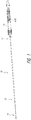
- a delivery device or system 10 is shown.
- the delivery system can be used deploy a prosthesis, such as a replacement heart valve, within the body.
- a prosthesis such as a replacement heart valve
- Replacement heart valves can be delivered to a patient's heart mitral valve annulus or other heart valve location in various ways, such as by open surgery, minimally-invasive surgery, and percutaneous or transcatheter delivery through the patient's vasculature.
- Example transfemoral approaches may be found in U.S. Pat. Pub. No. 2015/0238315, filed February 20, 2015 .
- delivery system 10 is described in connection with a percutaneous delivery approach, and more specifically a transfemoral delivery approach, it should be understood that features of delivery system 10 can be applied to other delivery system, including delivery systems for a transapical delivery approach. Further examples of devices, systems and methods are described in U.S. Provisional Application Nos. 62/163932, filed May 19, 2015 , and 62/210165, filed August 26, 2015 and U.S. Publication No. 2016/0317301 ( 15/141,684), filed April 26, 2016 .
- delivery system 10 as described herein can have components, features, and/or functionality similar to those described with respect to delivery systems, devices and methods described in at least paragraphs [0006]-[0037] and [0078]-[0170] of U.S. Provisional Application No. 62/163932, filed May 19, 2015 , including the description relating to Figures 1-40B .
- delivery system 10 as described herein can have components, features, and/or functionality similar to those described with respect to the systems, devices and methods described with respect to paragraphs [0171]-[0197] of U.S. Provisional Application No.
- the delivery system 10 can be used to deploy a prosthesis, such as a replacement heart valve as described elsewhere in this specification, within the body.
- the delivery system 10 can receive and/or cover portions of the prosthesis such as a first end 301 and second end 303 of the prosthesis 70 illustrated in Figure 3 below.
- the delivery system 10 may be used to deliver an expandable implant or prosthesis 70, where the prosthesis 70 includes the first end 301 and the second end 303, and wherein the second 303 end is configured to be deployed or expanded before the first end 301.
- the delivery system 10 can be relatively flexible. In some embodiments, the delivery system 10 is particularly suitable for delivering a replacement heart valve to a mitral valve location through a transseptal approach (e.g., between the right atrium and left atrium via a transseptal puncture).
- a transseptal approach e.g., between the right atrium and left atrium via a transseptal puncture.
- the delivery system 10 can include an elongate shaft assembly 12 comprising a proximal end 11 and a distal end 13, wherein a handle 14 is coupled to the proximal end of the assembly 12.
- the elongate shaft assembly 12 can be used to hold the prosthesis for advancement of the same through the vasculature to a treatment location.
- the delivery system 10 can further comprise a relatively rigid live-on sheath 51 surrounding the elongate shaft assembly 12 that can prevent unwanted motion of the elongate shaft assembly 12.
- the elongate shaft assembly 12 can include an implant retention area 16 (shown in Figures 2A-B with Figure 2A showing the prosthesis 70 and Figure 2B with the prosthesis 70 removed) at its distal end that can be used for this purpose.
- the elongate shaft assembly 12 can hold an expandable prosthesis in a compressed state at implant retention area 16 for advancement of the prosthesis within the body.
- the elongate shaft assembly 12 may then be used to allow controlled expansion of the prosthesis at the treatment location.
- the implant retention area 16 is shown in Figures 2A-B at the distal end of the delivery system, but may also be at other locations.
- the prosthesis 70 may be rotated in the implant retention area 16, such as through the rotation of the inner assembly 18 discussed herein.
- the elongate shaft assembly 12 can include one or more subassemblies such as an inner assembly 18, a mid shaft assembly 20, an outer sheath assembly 22, and nose cone assembly 31 as will be described in more detail below.
- the outer sheath assembly 22 can form an radially outer covering, or sheath, to surround an implant retention area 16.
- the mid shaft assembly 20 can be composed of a mid shaft 50 with its distal end attached to outer retention member or outer retention ring 40.
- the inner assembly 18 can be composed of an inner retention shaft 42 and an inner retention member 32.
- the most radially-inward assembly is the nose cone assembly 31 which includes the nose cone shaft 30 having its distal end connected to the nose cone 28.
- the elongate shaft assembly 12, and more specifically the nose cone assembly 31, inner assembly 18, mid shaft assembly 20, and outer sheath assembly 22, can be configured to deliver a prosthesis 70 positioned within the implant retention area 16 (shown in Figure 2A ) to a treatment location.
- One or more of the subassemblies can then be moved to allow the prosthesis 70 to be released at the treatment location.
- one or more of the subassemblies may be movable with respect to one or more of the other subassemblies.
- the handle 14 can include various control mechanisms that can be used to control the movement of the various subassemblies as will also be described in more detail below. In this way, the prosthesis 70 can be controllably loaded onto the delivery system 10 and then later deployed within the body.
- FIG 2A further shows an example of the prosthesis 70 that can be inserted into the delivery system 10, specifically into the implant retention area 16.
- the prosthesis is shown with only the bare metal frame illustrated.
- the implant or prosthesis 70 can take any number of different forms. A particular example of frame for a prosthesis is shown in Figure 3 , though it will be understood that other designs can also be used.
- the prosthesis 70 can include one or more sets of anchors, such as distal (or ventricular) anchors 80 extending proximally when the prosthesis frame is in an expanded configuration and proximal (or atrial) anchors 82 extending distally when the prosthesis frame is in an expanded configuration.
- the prosthesis can further include struts 72 which may end in mushroom-shaped tabs 74 at the first end 301 as well as a flap 81 surrounding the frame near the second end 303. Further discussion on the annular flap 81 can be found in U.S. App. No. 14/716,507, filed May 19, 2015 .
- the inner retention member 32, the outer retention ring 40 and the outer sheath assembly 22 can cooperate to hold the prosthesis 70 in a compacted configuration.
- the inner retention member 32 is shown engaging struts 72 at the proximal end of the prosthesis 70.
- slots located between radially extending teeth on the inner retention member 32 can receive and engage the struts 72 which may end in mushroom-shaped tabs 74 on the proximal end of the prosthesis 70.
- the outer retention ring 40 can be positioned over the inner retention member 32 so that the first end 301 of the prosthesis 70 is trapped therebetween, securely attaching it to the delivery system 10.
- the distal anchors 80 can be located in a delivered configuration where the distal anchors 80 point generally distally (as illustrated, axially away from the main body of the prosthesis frame and away from the handle of the delivery system).
- the distal anchors 80 can be restrained in this delivered configuration by the outer sheath assembly 22. Accordingly, when the outer sheath 22 is withdrawn proximally, the distal anchors 80 can flip positions to a deployed configuration (e.g., pointing generally proximally).
- Figure 2A also shows the proximal anchors 82 extending distally in their delivered configuration within the outer sheath assembly 22 and within the outer retention ring 40. In other embodiments, the distal anchors 80 can be held to point generally proximally in the delivered configuration and compressed against the body of the prosthesis frame.
- the delivery system 10 may be provided to users with a prosthesis 70 preinstalled.
- the prosthesis 70 can be loaded onto the delivery system shortly before use, such as by a physician or nurse.
- Figure 4-6 illustrate further views of delivery system 10 with different assemblies translated proximally and described in detail.
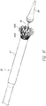
- FIG. 4 shows an outer sheath assembly 22 in its distal most position relative to nose cone 28.
- a live-on sheath 51 can be used to cover the outer sheath assembly 22 and provide structural support during bending, though its use is optional.
- the outer sheath assembly 22 is disposed so as to be slidable over the inner assembly 18, the mid shaft assembly 20, and the nose cone assembly 31.
- inner assembly 18 and the mid shaft assembly 20 can be a single piece tube or multiple pieces connected together to provide different characteristics along different sections of the tube.
- the illustrated outer sheath assembly 22 has a first segment 56, a second segment 58, and a third segment 60, where the first segment 56 is proximal to the second segment 58, and the second segment 58 is proximal to the third segment 60.
- the third segment 60 of the outer sheath is shown in contact with the proximal end of the nose cone 28. In this position, a prosthesis 70 can be held within the outer shaft assembly 22 for advancement of the same through the vasculature to a treatment location.
- the first segment 56 may be a tube and is preferably formed plastic, but could also be a metal hypotube or other material. A further discussion of the first segment 56 is below with respect to Figures 10A-10D .
- the second segment 58 can be a metal hypotube which in some embodiments may be cut or have slots.
- the tube 58 can be covered or encapsulated with a layer of ePTFE, PTFE, or other material so that the outer surface of the outer sheath assembly is generally smooth.
- the covered second segment 58 is shown in Figure 4 .
- the third segment 60 can be a tube formed of a plastic or metal material.
- the third segment is formed of ePTFE or PTFE.
- this sheathing material can be relatively thick to prevent tearing and to help maintain a self-expanding implant in a compacted configuration.
- the material of the third segment 60 is the same material as the coating on the cut hypotube 1058.
- the third segment 60 can include one or more wings or tabs 63, shown in Figure 4 , extending distally from a distal end of the third segment 60.
- the tabs 63 can be configured to bend, curve, or fold radially outward from the third segment 60.
- the one or more tabs 63 can facilitate loading of a replacement valve within the third segment 60 when the replacement valve is initially loaded into the delivery system 10.
- the one or more tabs 63 can be removed prior to use within a patient, such as shown in Figure 10 of U.S. Provisional App. No. 62/210,165 filed August 26, 2015 .
- the one or more tabs 63 can be formed by cutting the third segment 60 via methods including, but not limited to, laser cutting.
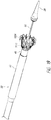
- Figure 5 illustrates the system 10 with the outer sheath assembly 22 removed (e.g., by pulling the outer sheath assembly 22 proximally), thus partially exposing the mid shaft assembly 20 including a portion of or all of a prosthesis (not shown) in the implant retention area 16.
- the mid shaft assembly 20 can be a single piece tube or multiple pieces connected together to provide different characteristics along different sections of the tube.
- it can be desirable, and/or needful, for the delivery system 10 to have greater flexibility at the distal end of the device, where flexibility is not as necessary for the proximal end.
- the illustrated mid shaft assembly 20 has a first segment 53, a second segment or mid shaft 50 distal to the first segment, and a third segment 40 distal the mid-shaft 50 being the outer retention ring 40.
- the first segment can extend distally away from the handle and be connected to the second segment or mid shaft 50 at the distal end of the first segment.
- the distal end of the second segment 50 can attach to the outer retention ring 40 (e.g., third segment).
- Each of the segments can be a tube, for example a metal or polymer tube, such as described with respect to the outer sheath assembly 22. Further discussion of the mid shaft 50 construction can be found below with respect to Figures 7-8 .
- the mid shaft assembly 20 can translate or slide over the inner assembly 18, which thereby causes the outer retention ring 40 to slide over the inner assembly 18 and encircle the inner retention member 32 described below.
- the outer retention ring 40 encircles a portion of the prosthesis 70, in particular the proximal portion, thus preventing the prosthesis 70 from expanding.
- the outer retention ring 40 can also circumferentially surround the inner retention member 32.
- the mid shaft assembly 20 can be translated proximally with respect to the inner assembly 18 into the proximally-retracted outer sheath assembly 22, thus exposing a proximal portion of the prosthesis 70 held within the outer retention ring 40.
- a taper 61 may be provided at the proximal end of the outer retention ring 40 to allow it to more easily slide into the outer sheath assembly 22. In this way the outer retention ring 40 can be used to help secure a prosthesis to or release it from the delivery system 10.
- the outer retention ring 40 can have a cylindrical or elongate tubular shape.
- the outer retention ring 40 can cover a substantial length of the prosthesis 70.
- the outer retention ring 40 can cover over 1/8, 1 ⁇ 4, 1/3, or 1 ⁇ 2 of the prosthesis 70.
- the outer retention ring 40 can cover a substantial length of the atrial anchors 82.
- the outer retention ring 40 can cover over 75%, over 80%, over 85%, or over 90% of the atrial anchors 82.
- the outer retention ring 40 can be about 15, 17, 17, 18, 19, or 20 mm in length or a range between those lengths. In some embodiments, the outer retention ring 40 can be between about 10 and about 30 mm in length.
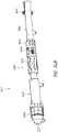
- Figure 6 shows approximately the same view as Figure 5 , but with the mid shaft assembly 20, including the outer retention ring 40 and mid shaft 50, removed, thereby partially exposing the inner assembly 18 (including the inner retention member 32 attached to inner retention shaft 42 ) and nose cone assembly 31 (including the nose cone shaft 30 attached to the nose cone 28 ).
- the inner assembly 18 can be composed of the inner retention shaft 42 with the inner retention member 32 attached to the distal end of the inner retention shaft 42.
- the inner retention shaft 42 can comprise a tube, such as a hypodermic tube or hypotube (not shown).
- the tube can be made from one of any number of different materials including nitinol, stainless steel, and medical grade plastics.
- the tube can be a single piece tube or multiple pieces connected together. Using a tube made of multiple pieces can allow the tube to provide different characteristics along different sections of the tube, such as rigidity and flexibility.
- a first segment (now shown) of the inner assembly 18 can be made of a hypotube can extend along a majority of the length of the inner assembly 18.
- metal hypotube extends from within the handle 16 at the proximal end towards the distal end up until a second segment (or inner retention shaft) 42 of the inner assembly 18 before the implant retention area 16.
- the hypotube can provide column strength (pushability) to the inner assembly.
- the handle 16 can allow for rotation of the second segment 42, which can allow for rotation of the prosthesis 70.
- a second segment 42 of the inner assembly 18 can be made of a more flexible material.
- the second segment 42 can comprise a wire such as a multi-stranded wire, wire rope, or wire coil.
- the wire can surround a more flexible tube, such as a plastic tube, or it may be formed as a tube without any additional inner materials or core.
- the wire can be a hollow core wire rope.
- the wire can provide the inner assembly 18 with strength, but it can also provide more flexibility to allow for navigating the curvosities of the vasculature, such as within the heart.
- the inner assembly 18 can also include a prosthesis retention mechanism such as an inner retention member 32 at a distal end of the second segment 42 that can be used to engage with the prosthesis, as discussed with respect to Figure 2A .
- the inner retention member 32 may be a ring and can include a plurality of slots configured to engage with struts 72 on the prosthesis 70.
- the inner retention member 32 can also be considered to be part of the implant retention area 16, and may be at the proximal end of the implant retention area 16.
- an outer retention member such as outer retention ring 40 can cover both the prosthesis and the inner retention member 32 to secure the prosthesis on the delivery system 10.
- the nose cone assembly 31 may be an elongate member, and in some embodiments, may have a nose cone 28 on its distal end.
- the nose cone 28 can be made of polyurethane for atraumatic entry and to minimize injury to venous vasculature.
- the nose cone 28 can also be radiopaque to provide for visibility under fluoroscopy.
- the nose cone shaft 30 may include a lumen sized and configured to slidably accommodate a guidewire so that the delivery system 10 can be advanced over the guidewire through the vasculature.
- the nose cone shaft 30 may be connected from the nose cone 28 to the handle, or may be formed of different segments such as the other assemblies. Further, the nose cone shaft 30 can be formed of different materials, such as plastic or metal, similar to those described in detail above.
- This view also illustrates that the nose cone shaft 36 can be slidably disposed within the inner assembly 18, thus allowing the nose cone shaft 28 (and thus nose cone 28 ) and the inner retention member 32 to move separately from one another during deployment and use.
- the inner retention member 32 and outer retention ring 40 and the delivery system 10 generally may be similar to those disclosed in U.S. Patent Nos. 8,414,644 and 8,652,203 . This is inclusive of the entire disclosure, including other apparatuses and methods described therein, and is not in any way limited to the disclosure of the inner and outer retentions and/or the delivery system.
- embodiments of the system 10 can be configured to be flexible when located in a patient and can allow for steering of the system 10 in a particular direction as desired by a user.
- embodiments of the system 10 can provide for controlled steerability to allow a user to better navigate and turn the distal end of the system 10 from the septum between the left and right atrial and into the native mitral valve annulus.
- no guidewire is required to steer the system 10.
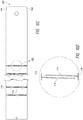
- FIG. 5 illustrates an embodiment of the second segment (e.g., mid shaft) 50 of the mid shaft assembly 20.
- the mid shaft 50 can be formed from a tube that comprises a series of discrete slots 402 that can be located along the length of the mid shaft 50.
- the slots 402 can be oriented substantially perpendicular to a longitudinal axis of the mid shaft 50 , with each slot having a proximal side, a distal side, and two circumferentially spaced apart opposite ends.
- the slots 402 in the mid shaft 50 rotate partially circumferentially around the mid shaft 50 .
- the slots 402 can form a gap configured to close upon application of a force which, in this particular slot configuration allows the mid shaft 50 to steer as guided by the configuration of the slots 402 , such as described below. By varying the characteristics of the slots 402 , different bending characteristics of the mid shaft 50 can occur.
- Figure 7 shows a flat pattern 900 of the mid shaft 50 shown in Figure 5 , where the flat pattern illustrates how the tube forming the mid shaft 50 is cut if the tube were to be longitudinally cut along its length to form slots 902 and laid flat.
- the tube formed from the flat pattern 900 can be formed by seamless drawn tubing where slots are laser cut into the tube.
- a spine 931 can be formed along its length between the ends of each slots 902 .
- the mid shaft 50 may be made of a laser cut metal tube, where the tube has a flat pattern 900 as illustrated in Figure 7 .
- the flat pattern 900 can have a series of slots 902 , in some embodiments greater than 40 slots 902 , along its length from the proximal end 904 to the distal end 906 .
- the slots 902 may be discrete slots, each spaced apart longitudinally from each other. While Figure 7 shows slots 902 that arc approximately equally spaced longitudinally from each other, other embodiments may include slots that have varying spacing there between. Slots 902 may be provided along substantially the entire length of the tube as illustrated, or may be provided only in portions along the length of the tube.
- the flat pattern 900 can be considered to include a center line 908 extending longitudinally from the proximal end to the distal end, with the slots 902 oriented perpendicular or substantially perpendicular to the center line.
- the slots 902 may be oriented perpendicular or substantially perpendicular to a longitudinal axis of the mid shaft 50 , and may extend or rotate circumferentially around the mid shaft 50 .
- Slots 902 can rotate circumferentially around the flat pattern 900 in the tubular form almost the entirety of the mid shaft 50 , for example over 80, 100, 120, 170, 180, 200, 220, 280, 300, 320, or 340 degrees circumferentially, leaving a small gap between lateral ends of each slot.
- proximal slots 921 may have the same circumferential position over a portion of the length of the tube (here the proximal slot section). As illustrated, there are 16 proximal slots 921 which may be identical to each other, each having a center portion located on the center line 908 and extending transversely from the center line 908 in a symmetrical pattern about the center line 908 (e.g., parallel to the longitudinal axis of the mid shaft 50 ).
- proximal slots 921 Distal to the proximal slots 921 are a plurality of transition slots 923 similar in shape to the proximal slots 921 , but having center portions that gradually move transversely further away from the center line 908 so that the transition slots 923 are angled relative to the center line 908 . As illustrated, there may be 5 such transition slots 923 . Whereas the proximal slots 921 are oriented perpendicular or substantially perpendicular to the longitudinal axis of the shaft 50 , the transition slots 923 are slightly angled relative to proximal slots 921 .
- Distal to the transition slots 923 are a plurality of distal slots 925 in a distal slot section, for example 21 distal slots 925 , which may have the same circumferential position over a proximal portion of the tube.
- the distal slots 925 may be identical to each other.
- the distal slots 925 may also be identical to the proximal slots 921.
- the distal slots 925 may each have a center portion that is circumferentially offset from the center portions of the proximal slots 921, and may continue longitudinally along the length of the tube from the proximalmost transition slot.
- the distal slots 925 may be oriented perpendicular or substantially perpendicular to the longitudinal axis of the shaft 50 and the center line 908.
- the slots 902 can be located at different circumferential positions along the length of the flat pattern 900.
- the center portions of the distal slots 925 and the center portions of the proximal slots 921 can be about 0-180° apart, preferably from about 45° to about 90°.
- Other circumferential changes such as, for example, 10, 20, 30, 40, 45, 50, 60, 70, 80, or 90° could be used as well.
- a majority of the slots 902 can be the proximal slots 921 and the distal slots 925, with only a small number of transition slots 923 between the two locations. Further, approximately half or more of the slots 902 can be proximal slots, though in other embodiments the number of slots 902 in these positions can change.
- the spine 931 will rotate along a circumference of the tube as well.
- the spine 932 will extend linearly along the proximal slots 921, turn at an angle to follow the transition slots 923, and again extend linearly along the distal slots 925.
- the slots 902 themselves can be generally identical throughout the length of the mid shaft 50, though there may be some minor variations. This can allow the proximal end 904 to generally always be activated (e.g., at least some slight bending) during application of a force at the distal end 906.
- Each individual slot 902 as illustrated in Figure 7 has a width (as measured circumferentially or transverse to the longitudinal axis of the mid shaft 50 ) which is much greater than its length (as measured along the longitudinal axis of the mid shaft 50 ).
- Each slot 902 forms three teeth which extend toward the distal end 906 of the mid shaft 50, with a larger tooth 916 located in the center of the slot 902 and two smaller teeth 918 symmetrically located on opposite sides of the larger tooth 916 extending at a slight angle away from the center line 908. Distal to each tooth, the slot 902 forms a center gap 919 and two side gaps 914 that the teeth move distally into when the mid shaft 50 is longitudinally compressed. Between the larger tooth 916 and the two side teeth 918 arc gaps 920 and circumfcrcntially outward from the smaller side teeth are triangular shaped gaps 912.
- each slot there is a W-shaped slot 910 which defines in part end gaps 922 having a greater length than the small end of the triangular slots 912. More generally, the ends of the slots 902 may be considered to be T-shaped, which can distribute strain evenly on the edge of the slots 902 and allow the mid shaft 50 to return to its original position after bending. All portions of each slot 902 can be connected as a single slot, or can be broken into a number of different pieces.
- the slot patterns described herein advantageously provide for a desired deformation of the slots 902 and therefore the mid shaft 50 as a force is applied to the mid shaft 50.
- a proximal force applied to a distal end of the mid shaft 50 will bend or steer the mid shaft 50 in a direction aligned with the slots 902, thereby closing the slots and bending the mid shaft 50 in the direction of the closure.
- the mid shaft 50 can bend in more than one dimension to follow the closure of the slots 902, allowing 3-dimensional bending (and thus 3-dimensional steering) in part due to the transition slots 923.
- the bending in the proximal and distal sections can occur simultaneously or in a two-part manner, depending on the size of the slots 902 and/or the strength of the force applied to the mid shaft 50.
- the proximal section having proximal slots 921 will experience the bending first, following by the transition section having transition slots 923, followed by the distal section having distal slots 925.
- the above referenced live-on sheath 51 can at least partially surround the proximal section and can stiffen the proximal section during delivery.
- the live-on sheath may at least partially cover the proximal section, providing an outer wall barrier to prevent bending of the proximal section and proximal slots 921, because it can be advantageous for the distal section and distal slots 925 to provide more guiding during implantation than the proximal slots 921.
- the proximal slots 921 it is advantageous for the proximal slots 921 to be activated by the least force because it can then always be activated during bending, thus providing stability for fine tuning the distal section 925 and providing torque to the entire delivery system 10 for additional positioning.
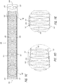
- Figures 8A-B show alternate embodiments of a flat pattern 1000 for mid shaft 50.
- the series of slots 1002 can extend generally linearly over the entire length of the mid shaft 50, extending from the proximal end 1004 to the distal end 1006, where the centers of the slots 1002 remain parallel to the longitudinal axis.
- a spine 1031 can be formed along its length between the ends of each slots 1002.
- the flat pattern 1000 of Figures 8A-8B will generally have a single plane of motion, which will be generally aligned with the center 1010 of the slots 1002.
- FIG. 8A-B shows slots 1002 that are approximately equally spaced longitudinally from each other, other embodiments may include slots that have varying spacing there between. Slots 1002 may be provided along substantially the entire length of the tube as illustrated, or may be provided only in portions along the length of the tube.
- the flat pattern 1000 can be considered to include a center line 1010 extending longitudinally from the proximal end 1004 to the distal end 1006, with the slots 1002 oriented perpendicular or substantially perpendicular to the center line.
- the slots 1002 may be oriented perpendicular or substantially perpendicular to a longitudinal axis of the mid shaft 50, and may extend or rotate circumferentially around the mid shaft 50.
- the slots can change in dimensions from the proximal end 1004 to the distal end 1006. This can allow for different articulation of the mid shaft 50 at different portions, creating a staged effect so that different sections of the mid shaft 50 bend at different times. Specifically, the further the distance from the distal end 1006, the greater the moment generated by each pound of pull, causing the proximal end 1004 to bend first, followed by the distal end 1006. Thus, a user can better control the articulation of the mid shaft 50.
- proximal slot section or proximal slots 1021 may be smaller over a portion of the length of the tube.
- proximal slots 1021 there are 16 proximal slots 1021 which may be identical to each other, each having a center portion located on the center line 1010 and extending transversely from the center line 1010 in a symmetrical pattern about the center line 1010.
- proximal slots 1021 Distal to the proximal slots 1021 are a plurality of middle slots 1023 (or a middle slot section) having a larger width than the proximal slots 1021 but remaining centered on center line 1010. As illustrated, there may be 21 such middle slots 1023.
- Distal to the middle slots 1023 are a plurality of distal slots 1025 (or a distal slot section), for example 18 distal slots 1025, which have a greater width than the middle slots 1023 and proximal slots 1021.
- the distal slots 1025 may be identical to each other.
- the distal slots 1025 may each be centered on center line 1010, and may continue longitudinally along the length of the tube from the distalmost middle slot 1023.
- Figure 8B has a similar configuration to Figure 8A , but there are transition sections between the proximal slot section and the middle slot section, and between the middle slot section and the distal slot section. In these transition sections, there are slots that gradually increase in width from the more proximal slot section to the more distal slot section.
- the spine 1031 will thus extend linearly parallel to center line 1010 but will increase in width from the proximal slots 1021 to the middle slots 1023 and further increase in width from the middle slots 1023 to the distal slots 1025.
- the decrease in slot width from the distal end 1006 to the proximal end 1004 can allow the mid shaft 50 to bend at the distal end 1006 prior to the proximal end 1004. Specifically, typically the higher the moment (e.g., force x distance from the force), the quicker the specific area will bend/deflect. In the mid shaft 50, the force is located at the distal end 1006, and thus the highest moment will be experienced at the proximal end 1004 as it is the farthest distance from the force.
- the moment e.g., force x distance from the force
- distal slots 1025 be larger than the proximal slots 1021, and thus the spine 1031 around the distal slots 1025 is smaller than around the proximal slots 1021, the distal end 1006 will bend first as there is significantly less material to bend and thus a lower moment is needed to bend, even though the distance from the force is the smallest.
- having the transition slots 1023 with a width between the width of the distal slots 1025 and the width of the proximal slots 1021 thus creating a generally gradual change in width, can provide stress relief that would otherwise concentrate near the proximal end 1004.
- the slots 1002 themselves can be generally identical in shape throughout the length of the mid shaft 50, though the dimensions (e.g., width) of the slots 1002 can vary.
- Each individual slot 1002 as illustrated in Figures 8A-B has a width (as measured circumferentially or transverse to the longitudinal axis of the mid shaft 50 ) which is much greater than its length.
- Each slot 1002 forms a single tooth 1016 which extend toward the proximal end 1004 of the mid shaft 50 and is located generally centered on longitudinal center line 1010. Proximal to the tooth 1016, the slot 1002 forms a center gap 1018 the tooth 1016 can move proximally into when the mid shaft 50 is longitudinally compressed.
- each slot there is a circular slot 1014 which defines in part end gaps having a greater length than the small end of a triangular slot 1012 located between the circular slot 1014 and the center gap 1018. All portions of each slot 1002 can be connected as a single slot, or can be broken into a number of different pieces.
- the flat pattern 1000 shown in Figures 8A-B can also allow for an organic compound bend. While the embodiment shown in Figures 8A-B generally only bends on a single plane, the mid shaft 50 can be configured to provide for slight bending outside of the plane, which can be used to properly place the implant 70 in a patient. Specifically, as the mid shaft 50 steers in the direction by a user, there can be a bending outside of the two dimensional plane. For example, there is space on the circumferential sides of the tooth 1016 for the tooth 1016 to move laterally, which gives some lateral flexibility (e.g., outside of the single plane of motion) when the mid shaft 50 impacts a portion of a patient's anatomy.
- the flat pattern 1000 can allow for a more forgiving pattern which can conform to the particular anatomy of a patient while the flat pattern 900 of Figure 7 is more rcpcatablc and provides for greater control as it docs not conform to the anatomy.
- a pull wire 612 (such as a 0.4572 mm (0.018 inch) diameter pull wire) can be used to connect the outer retention ring 40 to the handle 14.
- the handle 14 can have a steering knob/actuator 610 (shown in Figure 1 ) in order to apply a force and control the bending of the mid shaft 50.
- the pull wire 612 can be connected to the nose cone 28, thereby providing a steering point more distal than the outer retention ring 40.
- the steering knob 610 can compensate for foreshortening of the delivery system 10 during bending. As the different components of the delivery system 10 bend (for example, the mid shaft bending to close slots 402 or the hypotube 150 of the outer sheath assembly 22 bending to close slots 152 described below), the mid shaft 50 and the outer sheath assembly 22 will reduce in length due to the closure of the slots, which could cause accidental release of prosthesis 70.
- the steering knob 610 can be configured to move the outer sheath assembly 22 distally during activation of the steering knob 610, while simultaneously pulling on the pull wire 612. This can prevent unwanted relative motion of the components of the delivery system 10 or unbalanced forces, in particular unwanted release of the prosthesis 70.
- the steering knob 610 in the handle 14 can be connected to a pull wire 612 generally at the proximal end of the system 10.
- the pull wire 612 can extend through the lumen of the mid shaft 50 and on the outside of the inner assembly 18.
- the pull wire 612 can connect to the outer retention ring connecter 614 which connects the distal portion of the mid shaft 50 to the outer retention ring 40.
- the outer retention ring connecter 614 can act as a weld spot for the pull wire 612 through, for example, a groove in the outer retention ring connector 614.
- the outer retention ring connector 614 can be connected to the mid shaft 50 by a series of rivets, though the attachment mechanism is not limiting.
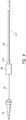
- the pull wire 612 can be connected to the handle 14 through a proximal wire connector 1200 shown in Figures 12A-12B having a proximal end 1202 and a distal end 1204.
- the proximal wire connector 1200 has a generally tubular shape which can be located/attached within a housing of the handle 14.
- the proximal wire connector 1200 can have a length of about 12.7 mm (0.50 inches).
- the pull wire 612 can extend through an aperture 1212 forming a longitudinal lumen along a length of the proximal wire connector 1200 at a distal end 1204.
- pull wire 612 can attach within the longitudinal lumen radially inward from a generally tear-drop shaped groove 1206 having a larger end 1208 nearest the proximal end 1202 and a smaller end 1210 near the distal end 1204.
- the groove 1206 can extend through a radius of the proximal wire connector 1200 to meet with the longitudinal lumen.
- the larger end 1208 can have a radius of curvature of about 6.35 mm (0.250 inches) and the smaller end 1210 can have a radius of curvature of about 0.127 mm (0.0050 inches).
- the pull wire 612 can then be welded in place in the longitudinal lumen radially inward from the larger end 1208.
- the tear-drop shaped groove 1206 is advantageous as the amount of heat the pull wire 612 is exposed to during welding decreases from the proximal end 1202 to the distal end 1204 as more mass is present neared the distal end 1204. Thus, the weld can be more consistent and less prone to issues caused by any heat-affected-zone during welding. Further, whereas most welding occurs at a 20% loss, the tear-shaped groove 1206 allows for about 5% loss or less.
- the proximal wire connector 1200 can be placed in a channel in handle 14 that narrows at one point distal to the proximal wire connector 1200.
- the channel can be pulled proximally by the steering knob 610 and once the proximal wire connector 1200 abuts the narrowed portion of the channel on its distal end, the proximal wire connector 1200 (and thus the pull wire 612 ) will be pulled proximally along with the channel, creating a proximal force on the pull wire 612.
- the mid shaft 50 will bend in the direction of the slot openings.
- the slot pattern on the mid shaft 50 will cause the mid shaft 50 to bend along the direction of the slots 402 with the enactment of the pull wire 612 force.
- the mid shaft 50 can bend in at least two directions, thus giving the device 10 3-dimcnsional stccrability.
- the disclosed method is advantageous as the pull wire 612 will not be put under compression, which could lead to kinking.
- the mid shaft 50 can translate back (e.g., "spring back") to its original position. This can occur at least partially due to the material (e.g., nitinol) and partially due to the construction of the ends of slots 902, which are generally T-shaped. This can be advantageous because, as discussed below, the pull wire 612 will not be compressed, thus avoiding kinks. In some embodiments, the mid shaft 50 will remain in the bent configuration even upon removal of the force. In some alternate embodiments, a second pull wire can be used, located in a different portion of the mid shaft 50. For example, the second pull wire can located 90° or 180° from the pull wire 612 , thus allowing for two-way steering of the mid shaft 50. A user can operate both pull wires independently, or they can operate in tandem with one another to produce the desired bend in the mid shaft 50 .
- the outer sheath assembly 22 can be composed of a number of different parts, namely a first segment 56 a second segment 58 , and a third segment 60. These different segments can have different features, builds, or constructions allowing for the segments to have properties advantageous to that particular section.
- first segment 56 which can be in the tube of a form having a lumen throughout its length.
- Figures 10A-10D illustrate the first segment 56 in an unrolled configuration, or a flat pattern for the tube.
- This segment 56 can be formed from laser cut stainless steel, though the particular material or method of cutting is not limiting.
- the first segment can be formed from a series of transverse and longitudinal slot pairs 710 , which are designed to transmit torque (e.g., rotating the delivery system 10 clockwise/counter-clockwise) while being flexible.
- the delivery system 10 can be rotated anywhere between 0 to 180° to reposition the prosthesis 70.
- Each slot of the slot pairs 710 can be composed of a shorter longitudinal slot 712 and a longer circumferential slot 714 with its end connected approximately at the middle of the longitudinal slot 712.
- the circumferential slot 714 can be slightly on angle from the longitudinal slot 712 and thus not perpendicular to the longitudinal axis.
- each of the slot pairs 710 can form a generally T-shaped pattern.
- the slot patterns can be formed with circumferential slots 714 of each slot pair generally overlapping one another circumferentially and spaced apart in the longitudinal direction.
- the longitudinal slots 712 of the pair 710 can then be located on circumferentially opposite sides of circumferential slots 714 so that they can each longitudinally overlap both of the longitudinal slots 712.
- These slot pairs 710 can then be repeated around the circumference of the first segment 56 to form slot rings 716.
- the pairs 710 can be spaced apart on the slot rings 714 to provide for tensile strength.
- the slot rings 714 can be repeated along the length of the first segment 56, wherein they can be repeated at a length of about 6.3754 mm (0.251 inches).
- the slot rings 716 can extend along approximately 971.5754 mm (38.251 inches) of the first segment 56. In some embodiments, the slot rings 716 are not found in a portion at the beginning and end of the first segment 56. This portion can be about 18.2626 mm (0.719 inches) in length. Any number of slot rings 716 can be used, and the number of slot rings 716 is not limiting.
- the longitudinal slots 712 can have a length of about 12.7, 15.24, 15.494, 17.78 or 20.32 mm (0.5, 0.6, 0.61, 0.7, or 0.8 inches), though the particular length is not limiting. Further, the longitudinal slots 712 can have a width of about 0.0127, 0.0254, 0.0381 or 0.00508 mm (0.0005, 0.001, 0.0015, or 0.0002 inches). Longitudinal slots 712 of the slot pairs 712 can be spaced about 7.6708 mm (0.302 inches) apart.
- the circumferential slots 714 can have a width (as measured circumferentially or transverse to the longitudinal axis of the mid shaft 50 ) of about 7.0231 mm (0.2765 inches).
- the circumferential slots 714 can have a width that increases in thickness, wherein the thickness portion of the circumferential slots 714 can be located in the middle of the circumferential slots 714, thus forming an extended ovaloid shape.
- This ovaloid can have a radius of about 47.7774 mm (1.881 inches).
- the thickness of the circumferential slots 714 can transition from approximately 0.0254 mm (0.001 inches) at the beginning and end of the circumferential slots 714 to about approximately double in thickness.
- Circumferential slots 714 of the slot pairs 710 can have an overlap of approximately 6.3754 mm (0.251 inches). They can be spaced apart by approximately 0.6604 mm (0.026 inches).
- Figure 10A has a proximal end 702 that is generally flat, whereas Figure 10C shows a proximal end 702 which has a pair of notches 704 which can help align the part with the handle 14, for example providing an audible or tactile "click" when installed properly.
- embodiments of the disclosed slot configuration can maintain strength and torque-transmission of, for example, stainless steel, while providing new flexibility.
- the configuration can handle compression, tension, and torque transmission with nearly 1:1 with no stretching.
- a knob on the handle 14 can translate the outer sheath assembly 22 wherein every inch of turning of the knob results in an inch of translation of the outer sheath assembly 22, hence the 1:1 ratio.
- This is advantageous over other types of shafts, such as those formed of PEBAX, which would act like a rubber band where a user would see no response for an inch of travel of the knob as the PEBAX would stretch the whole time, and a user would be unsure when the translation would reach the distal end. The distal end would then translate suddenly and with no control, which could cause serious problems in a patient.
- embodiments of the disclosed outer sheath assembly 22 can have minimal stretching. For example, if a 40lb weight were attached to the outer sheath assembly, it would only stretch about 2.54 mm (0.1 inches) over an approximate 1016 mm (40 inches) of length. Other types of sheathes, again such as PEBAX, would stretch up to 38.1 mm (1.5 inches) with the same application of force.
- the outer sheath assembly 22 can include a third segment 60 and a second segment 58, the second segment 58 being proximal to the third segment 60.
- the third segment 60 may be larger in inner diameter and outer diameter than the second segment 58, and may be sized in length and inner diameter to receive a prosthesis 70 as described herein in a collapsed configuration. These two segments can each have a different diameter, thereby forming a stepped configuration.
- the second segment 58 relative to the overall length of the delivery system 10, is still generally positioned at a distal portion of the delivery system 10 while the delivery system 10 is being used to deliver the replacement valve towards the in situ implantation site.
- the outer sheath assembly 22 may include other segments positioned proximal of the second segment 58. Such segments may, for example, couple the second segment 58 to a handle of the delivery system 10.
- the third segment 60 can be positioned radially outward from a replacement valve when the delivery system 10 is in an initial, delivery configuration such that the replacement valve is maintained in the delivery system 10 in an undeployed configuration.
- the second segment 58 can be formed from a hypotube 150 (such as a nitinol hypotube) as shown in the embodiment in Figures 11A-E showing a flat pattern of the hypotube 150.
- the hypotube 150 can have a plurality of spaced slots 152 extending along the length from a distal end 156 to a proximal end 154 of the hypotube 150.
- a spine 161 can be formed along its length between the ends of each slots 152.
- the slots 152 can be generally open and wide towards the middle, thereby allowing ePTFE to pass through the slots so that the first side and second side can be sintered together during manufacturing, thereby fully covering the hypotube 150 in ePTFE.
- the slots 152 can be a number, e.g., greater than 40, generally repeating and identical slots that extend along the length of the hypotube 150. Slots 152 may be provided along substantially the entire length of the tube as illustrated, or may be provided only in portions along the length of the tube. In some embodiments, as shown in Figure 11B-C , the hypotube 150 may have a pair of rectangular slots 157 on its proximal and distal ends 156. The rectangular slots 157 can differ in size between the two ends or may be the same in size. In some embodiments, the hypotube 150 may only have the rectangular slots 157 on the proximal end 154, and instead the spaced slots 152 can extend almost to the distalmost end 156. This configuration is shown in Figure 11A .
- the slots 152 may be formed with a generally H-shaped structure centered on the hypotubc 150.
- the slots 152 may have a generally T-shaped ends 153 spaced circumferentially opposite one another on the flat hypotube 150. These T-shaped ends 153 can be connected by a circumferential slot 155 extending circumferentially between the two slots.
- the circumferential slot 155 can change in height between the two w-shaped slots. For example, the circumferential slot 155 can have a greater height in the middle than where the circumferential slot 155 connects to the T-shaped ends 153.
- each of the slots 152 may generally have the same dimensions along the length of the hypotube 150.
- the slots 152 may change in width between the proximal end 154 to the distal end 156.
- the proximal end may have slots 152 having a smaller width than the slots at the distal end 156.
- the slots 152 can progressively increase in width from the proximal end 154 to the distal end 154, where the majority of slots are the large width slots.
- the first three slots 152 from the proximal end can have a shorter width than the slots 152 on the proximal end, with the first three slots 152 increasing in width from the proximalmost slot to the distalmost slot of the first three slots 152. Any number of slots and slot configurations can be used.
- This progression of slot size can be useful in making strain apply more evenly across the hypotube 150 as a proximal force applied to the distal end 154 tends to apply first to the proximal-most slot.
- smaller slots 152 at the proximal end 154 can withstand a greater force as there is more material.
- the spine 161 will increase in width from the proximal end 154 to the distal end 156, while remaining generally parallel with the longitudinal axis of the hypotube 150.
- slots can be used.
- slots can be spaced offset from one another to create, for example, a spiral pattern.
- adjacent slots can be offset by about 90°, thereby forming a repeating pattern along the longitudinal lengths of the hypotube 150.
- the outer sheath assembly 22 can include a lumen running therethrough to allow the sheath assembly 22 to be moveable or slideable relative to components contained therein.
- the walls forming the third segment 60 and/or the walls forming the second segment 58 can be formed from one or more materials, such as PTFE, ePTFE, PEBAX, ULTEM, PEEK, urcthanc, nitinol, stainless steel, and/or any other biocompatible material.
- the third segment 60 is formed from one or more materials which allow the third segment 60 to be compliant and flexible while still maintaining a sufficient degree of radial strength to maintain a replacement valve within the third segment 60 without substantial radial deformation which could increase friction between the third segment 60 and a replacement valve contained therein, sufficient column strength to resist buckling of the third segment 60, and sufficient tear resistance to reduce the likelihood that the replacement valve causes the third segment 60 to tear. Flexibility of the third segment 60 can be advantageous, particularly for a transseptal approach. For example, while being retracted along a curved member, the third segment 60 can follow the curved member without applying significant forces upon the curved member which may cause the curved member to decrease in radius. Rather, the third segment 60 can bend and/or kink as it is being retracted along such a curved member such that the radius of the curved member is maintained.
- the hypotube 150 can be optimized for maximum flexibility and minimum strain while providing for structural rigidity.
- the hypotube 150 can be formed from stainless still instead of nitinol, which can advantageously incase processing/manufacturing, though other materials can be used as well.
- the hypotube 150 can be about 139.7, 152.4, 160.02, 165.1, 177.8 or 190.5 mm (5.5, 6.0, 6.3, 6.5, 7.0, or 7.5 inches) in length, the particular dimensions of the hypotube 150 is not limiting.
- the delivery system 10 can be used in a method for percutaneous delivery of the replacement mitral valve to treat patients with moderate to severe mitral regurgitation.
- the below methods are just a few examples of the how the delivery system may be used. It will be understood that the delivery systems described herein can be used as part of other methods as well.
- the delivery system 10 can be placed in the ipsilateral femoral vein 1074 and advanced to the right atrium 1076. A transseptal puncture using known techniques can then be performed to obtain access to the left atrium 1078. The delivery system 10 can then be advanced in to the left atrium 1078 and then to the left ventricle 1080. Figure 13 shows the delivery system 10 extending from the ipsilateral femoral vein 1074 to the left atrium 1078.
- a guide wire is not necessary to position the delivery system 10 in the proper position, although in other embodiments, one or more guide wires may still be used.
- a user can be able to steer the delivery system 10 through the complex areas of the heart in order to place a replacement mitral valve in line with the native mitral valve.
- This task can be performed with or without the use of a guide wire with the above disclosed system.
- the distal end of the delivery system can be inserted into the left atrium 1078.
- a user can then turn the steering knob 610 on the handle 14 in order to cause bending of the mid shaft 50, and thus the distal end of the delivery system 10.
- a user can then continue to pass the bent delivery system through the transseptal puncture and into the left atrium 1078.
- a user can then further manipulate the steering knob 610 to create an even greater bend in the mid shaft 50.
- a user can torque the entire delivery system 10 to further manipulate and control the position of the delivery system 10. In the fully bent configuration, a user can then place the replacement mitral valve in the proper location.
- This can advantageously allow delivery of a replacement valve to an in situ implantation site, such as a native mitral valve, via a wider variety of approaches, such as a transseptal approach.
- Figure 14 illustrates the bending motion of the outer sheath assembly 22.
- the mid shaft 50 (not shown but within outer sheath assembly 22 ) can be bent through actuation of the steering knob 610.
- the mid shaft 50 As the mid shaft 50 is bent, it will press against an inner surface of the outer sheath assembly 22, thereby forcing the outer sheath assembly 22 to bend along with the mid shaft 50.
- an inner surface of the mid shaft 50 will press against an outer surface of the inner retention shaft 42, which will press against the nose cone shaft 30, thus bending the inner retention shaft 42 and the nose cone shaft 30 along with the mid shaft 50. Accordingly, the distal end of the delivery system 50 will bend as shown in Figure 14 due to the actuation of the mid shaft 50.
- the outer sheath assembly 22, specifically second segment 58 can be substantially bent to conform to the bending of the mid shaft 50.
- the embodiment shown in Figure 14 can allow for three-dimensional bending of the delivery system 10.
- the nose cone 28 can be angled approximately 90° from a longitudinal axis of the delivery system 10 when in an unbent position.
- Figure 14 shows one particular position, and the delivery system 10 can be bent into other angles as well.
- the delivery system 10 can be bent in a manner to align with the anatomy of a heart, thus allowing the delivery system 10 to pass through the transseptal puncture and position the delivery system 10 to deliver a prosthesis 70 into the mitral valve annulus.
- the bending experienced by the delivery system especially between the right atrium 1076 and the mitral valve are relatively complex and are generally not in a single plane, although single plane flexibility can be used. This part of the delivery system may experience bending between 110-180 degrees and typically between 130-160 degrees, of course this is dependent on the actual anatomy of the patient.
- FIG 15 illustrates a schematic representation of an example of a replacement heart valve (prosthesis 70 ) positioned within a native mitral valve of a heart 83. Further details regarding how the prosthesis 70 may be positioned at the native mitral valve are described in U.S. Patent Publication No. 2015/0328000 ( 14/716,507), filed May 19, 2015 , including but not limited to Figures 13A-15 and paragraphs [0036]-[0045].
- a portion of the native mitral valve is shown schematically and represents typical anatomy, including a left atrium 1078 positioned above an annulus 106 and a left ventricle 1080 positioned below the annulus 106.
- the portion of the prosthesis 70 disposed upstream of the annulus 106 (toward the left atrium 1078 ) can be referred to as being positioned supra-annularly.
- the portion generally within the annulus 106 is referred to as positioned intra-annularly.
- the portion downstream of the annulus 106 is referred to as being positioned sub-annularly (toward the left ventricle 1080 ).
- the replacement heart valve (e.g., prosthesis 70 ) can be disposed so that the mitral annulus 106 is between the distal anchors 80 and the proximal anchors 82.
- the prosthesis 70 can be positioned such that ends or tips of the distal anchors 80 contact the annulus 106 as shown, for example, in Figure 15 .
- the prosthesis 10 can be positioned such that ends or tips of the distal anchors 80 do not contact the annulus 106.
- the prosthesis 70 can be positioned such that the distal anchors 80 do not extend around the leaflet 108.
- the prosthesis 70 can be at least partially surrounded by an annular flap 81 between the distal anchors 82 and the proximal anchors 82.
- This flap 81 can wrap around the frame of the prosthesis 70 and help position the prosthesis 70 in the desired position in the body.
- the replacement heart valve 70 can be positioned so that the ends or tips of the distal anchors 80 are on a ventricular side of the mitral annulus 106 and the ends or tips of the proximal anchors 82 are on an atrial side of the mitral annulus 106.
- the distal anchors 80 can be positioned such that the ends or tips of the distal anchors 80 are on a ventricular side of the native leaflets beyond a location where chordae tendineae 110 connect to free ends of the native leaflets.
- the distal anchors 80 may extend between at least some of the chordae tendineae 110 and, in some situations such as those shown in Figure 15 , can contact or engage a ventricular side of the annulus 106.
- the distal anchors 80 may not contact the annulus 106, though the distal anchors 80 may still contact the native leaflet 108. In some situations, the distal anchors 80 can contact tissue of the left ventricle 104 beyond the annulus 106 and/or a ventricular side of the leaflets.
- the distal anchors 80 (along with the frame) can be moved toward the ventricular side of the annulus 106 with the distal anchors 80 extending between at least some of the chordae tendineae 110 to provide tension on the chordae tendineae 110.
- the degree of tension provided on the chordae tendineae 110 can differ. For example, little to no tension may be present in the chordae tendineae 110 where the leaflet 108 is shorter than or similar in size to the distal anchors 80. A greater degree of tension may be present in the chordae tendineae 110 where the leaflet 108 is longer than the distal anchors 80 and, as such, takes on a compacted form and is pulled proximally. An even greater degree of tension may be present in the chordae tendineae 110 where the leaflets 108 are even longer relative to the distal anchors 80.
- the leaflet 108 can be sufficiently long such that the distal anchors 80 do not contact the annulus 106.
- the proximal anchors 82 can be positioned such that the ends or tips of the proximal anchors 82 are adjacent the atrial side of the annulus 106 and/or tissue of the left atrium 1078 beyond the annulus 106. In some situations, some or all of the proximal anchors 82 may only occasionally contact or engage atrial side of the annulus 106 and/or tissue of the left atrium 1078 beyond the annulus 106. For example, as illustrate in Figure 15 , the proximal anchors 82 may be spaced from the atrial side of the annulus 106 and/or tissue of the left atrium 1078 beyond the annulus 106. The proximal anchors 82 could provide axial stability for the prosthesis 10.
- some or all of the proximal anchors 82 may not contact an annular flap 81. This may occur when the annular flap 81 is in a collapsed configuration although it may also occur when the annular flap 81 is in an expanded configuration. In some situations, some or all of the proximal anchors 82 may contact the annular flap 81. This may occur when the annular flap 81 is in an expanded configuration although it may also occur when the annular flap 81 is in a collapsed configuration. It is also contemplated that some or all of the proximal anchors 82 may contact the atrial side of the annulus 106 and/or tissue of the left atrium 1078 beyond the annulus 106
- the annular flap 81 can be positioned such that a proximal portion of the annular flap 81 is positioned along or adjacent an atrial side of the annulus 106.
- the proximal portion can be positioned between the atrial side of the annulus 106 and the proximal anchors 82.
- the proximal portion can extend radially outward such that the annular flap 81 is positioned along or adjacent tissue of the left atrium 1078 beyond the annulus 106.
- the annular flap 81 can create a seal over the atrial side of the annulus 106 when the flap 81 is in the expanded state.
- FIG 16 illustrates an alternate example of a valve prosthesis 1010 which can be used in conjunction with the delivery systems disclosed herein.
- the illustrated prosthesis 1010 includes a frame 1020 that may be self-expanding or balloon expandable.
- the prosthesis 1010 may be a replacement valve that can be designed to replace a damaged or diseased native heart valve such as a mitral valve, as discussed above.
- the additional features of the replacement valve are not shown in Figure 16 in order to more clearly illustrate features of the frame 1020.
- the prosthesis 1010 is not limited to being a replacement valve.
- FIG 16 that only a front portion of the frame 1020 is shown for further ease of illustration.
- the frame 1020 can be made of many different materials, but is preferably made from metal.
- the frame 1020 can be made from a shape memory material, such as nitinol.
- a wire frame or a metal tube can be used to make the frame 1020.
- the wire frame of a metal tube can be cut or etched to remove all but the desired metal skeleton.
- a metal tube is laser cut in a repeating pattern to form the frame 1020.
- one of the anchors 1022 can include an eyelet, which can help manufacturing with alignment.
- the eyelet can serve as a reference position for frame dimensional measurements as well as alignment. However, the eyelet may not be included in all examples.
- the flat pattern can be cut from a metal tube and then the tube can be shaped and/or bent to the expanded shape shown in Figure 16 .
- the frame 1020 is self-expanding so that it naturally assumes the expanded shape or configuration.
- the frame 1020 can further be expanded and/or compressed and/or otherwise worked to have the desired shape or shapes, such as for introduction and implantation.
- the frame when in an expanded configuration, such as in a fully expanded configuration, has a bulbous or slightly bulbous shape, with a middle portion 1033 being larger than the proximal 1032 and distal 1034 ends.
- the inside diameter of the both ends can be the same, or it can be bigger on one end than the other, while still having a middle portion 1033 larger than both the proximal and distal ends 1032/1034.
- the effective diameter of the distal frame end 1034 is smaller than the effective diameter of the middle portion 1033.
- the bulbous shape of the frame 1020 can advantageously allow the frame 1020 to engage a native valve annulus or other body cavity, while spacing the inlet and outlet from the heart or vessel wall.
- the frame 1020 may not have a bulbous portion, and can have substantially the same outer dimension along its entire length (e.g., cylindrical), or it may have one end larger than the other end.
- the prosthesis 1010 and frame 1020 may be similar to the replacement heart valves and associated frames disclosed in U.S. Patent No. 8,403,983 , U.S. Publication Nos. 2010/0298931 , 2011/0313515 , 2012/0078353 , 2014/0277390 , 2014/0277422 , and 2014/0277427 , and U.S. Pat. Pub. No. 2016/0317301 ( 15/141,684), filed April 26, 2016 . This is inclusive of the entire disclosure and is not in any way limited to the disclosure of the replacement heart valves and associated frames.
- FIG. 16 illustrates the frame in an expanded configuration with a number of proximal struts 1012 that extend substantially longitudinally to enlarged proximal ends 1013.
- a proximal row of circumferentially-expansible struts 1017 connects the proximal struts 1012, having a zig-zag or undulating shape such that between each proximal strut 1012, the struts 1017 form a V-shape. From the distal ends of each of the V's, vertical struts 1015 extend substantially longitudinally in a distal direction.
- the distal ends of the vertical struts 1015 then connect to a row of diamond-shaped cells 1023 formed by a plurality of circumferentially-expansible struts 1014 having a zig-zag or undulating shape.
- the proximalmost row of struts 1014 extend distally away from the distal ends of the vertical struts 1015 in a V-shapc, thereby forming hexagonal-shaped cells 1021 bounded by the proximal row of struts 1017, the vertical struts 1015, and the proximalmost row of struts 1014.
- the example of Figure 16 further comprises a second, distal row of diamond-shaped cells 1023 further defined by additional circumferentially-expansible struts 1014, wherein the proximalmost corner of the second row of diamond-shaped cells 1023 coincides with the distalmost corner of the hexagonal-shaped cells 1021 and the side corners of the diamond-shaped cells in the first, proximal row.
- the proximal struts 1012 and the vertical struts 1015 may be arranged so that they are parallel or generally or substantially parallel to a longitudinal axis of the frame.
- the proximal struts 1012 and the vertical struts 1015 can further be inclined relative to the longitudinal axis so that the proximal ends of the proximal struts 1012 are closer to the longitudinal axis than distal ends of the proximal struts 1012.
- the longitudinal axis of the frame 1020 may be defined as the central axis that extends through the center of the frame 1020 between the proximal 1032 and distal 1034 ends.
- the illustrated example includes one ring, or row of hexagonal or generally hexagonal cells 1021 shown in proximal portion 1016 of the frame 1020, and two rows of diamond-shaped cells 1023 shown in distal portion 1018.
- the proximal portion 1016 includes the portion of the hexagonal cells 1021 extending proximally from the distal end of vertical struts 1015 and may be considered to be or to include a substantially non-foreshortening portion. Foreshortening refers to the ability of the frame to longitudinally shorten as the frame radially expands.
- the distal portion 1018 includes the diamond-shaped cells 1023 extending distally from the distal ends of the vertical struts 1015 and may be considered a foreshortening portion.
- the hexagonal cells 1021 can be irregular hexagons.
- the hexagonal cells 1021 can be symmetrical about a vertical axis extending from proximal to distal ends of the hexagonal cell 1021.
- Vertical struts 1015 can form opposite sides, while circumferentially-expansible struts 1014 of two adjacent diamond-shaped cells 1023 in the proximalmost row can form a base of the hexagonal cell 1021 ending at a distalmost corner that is distal to the distal ends of the vertical struts 1015.
- circumferentially-expansible struts 1014 can connect to the vertical struts 1015.
- the proximal row of circumfcrcntially-cxpansiblc struts 1017 can form the upper sides of the hexagonal cell 1021 that extend to a proximalmost corner of the hexagonal cell 1021 that is proximal to the proximal ends of vertical struts 1015.
- These circumferentially-expansible struts 1017 can connect to the proximal ends of the vertical struts 1015.
- two of the sides of the hexagonal cells 1021 can be one length, while the other four sides of the hexagonal cells 1021 can be a greater length.
- the two sides with the same length can be generally parallel to one another.
- the frame 1020 has a proximal portion 1016 and a distal portion 1018.
- the proximal struts 1012 and the majority of the hexagonal cells 1021 are included in the proximal portion 1016, while circumferentially-expansible struts 1014 form the distal portion 1018 having a first, proximal row of diamond-shaped cells 1023 and a second, distal row of diamond-shaped cells 1023.
- adjacent cells between the proximal row and the distal row may share common struts.
- the diamond-shaped cells 1023 in the second, distal row may have a larger longitudinal height than the diamond-shaped cells 1023 in the first, proximal row.
- the struts 1014 become more parallel with respect to the longitudinal axis of the frame, causing an outer diameter of the frame to decrease and the longitudinal length of the frame to increase in the distal portion 1018.
- the longitudinal length of the frame can decrease due to foreshortening of the diamond-shaped cells 1023 in distal portion 1018.
- the frame length does not substantially change length in the proximal portion 1016 due to the vertical struts 1015, although the proximal row of circumferentially-expansible struts 1017 in the proximal portion 1016 may allow for some foreshortening.
- the frame 1020 shown in Figure 16 can have a relatively squat configuration.
- the ratio of the width of the largest portion of the frame 1020 to the height (e.g., extending from the proximal 1032 to distal end 1034 ) of the frame 1020 when the frame is in its expanded configuration can be about 3:1, about 2.5:1, about 2.0:1, about 1.5:1, about 4:3, about 1.3:1, about 1.25:1, or about 1.0:1.
- the width at the largest portion of the frame 1020 can be greater than the height.
- the frame 1020 can have a larger aspect ratio than the prosthesis 70 shown in Figure 15 .
- the height of portion 1016 can be greater than, equal to, or less than the height of portion 1018.
- the height of proximal portion 1016 can be approximately 1 ⁇ 2 the height of distal portion 1018.
- the frame 1020 can have an overall height of about 32mm (or about 32mm).
- the frame 1020 can have an inner diameter of 40mm (or about 40mm).
- the frame 1020 can have a height of 29, 30, 31, 33, 34, 35, or 36 mm (or about 29, about 30, about 31, about 33, about 34, about 35, or about 36mm).
- Foreshortening of the frame 1020 can be used to engage and secure the prosthesis to intralumenal tissue in a body cavity, for example tissue at or adjacent a native valve, such as a native valve annulus and/or leaflets.
- Opposing anchors 1022, 1024 can be constructed on the frame 1020 so that portions of the anchors, such as tips or ends 1026, 1028, move closer together as the frame foreshortens. As one example, this can allow the anchors 1022, 1024 to grasp tissue on opposite sides of the native mitral annulus to thereby secure the prosthesis at the mitral valve.
- one set of anchors (such as anchors 1024 ) are secured to or grasp tissue, while the other set of anchors (such as anchors 1022) are used to provide stabilization and help align the prosthesis, and may or may not directly engage tissue, as described further below.
- the anchors 1022, 1024 and anchor tips 1026, 1028 are preferably located along the frame 1020 with at least part of the foreshortening portion positioned between the anchors so that a portion of the anchors will move closer together with expansion of the frame.
- distal anchors 1024 are connected to the distal portion 1018, and may extend from distalmost corners of the diamond-shaped cells 1023. As illustrated, the distal anchors 1024 extend distally from distalmost corners of the proximal row of diamond-shaped cells 1023, such that the second, distal row of diamond-shaped cells 1023 extend longitudinally alongside a portion of the distal anchors.
- each of the anchors 1022, 1024 is positioned or extends generally radially outwardly from the frame 1020 so that the anchor tips 1026, 1028 are generally spaced away or radially outward from the rest of the frame 1020 and from where the base of the anchors connect to the frame.
- the anchor tips may be located radially outward from the middle portion 1033 of the frame, with the tips 1026 and 1028 being axially spaced from one another.
- the middle portion 1033 which has the largest cross-sectional dimension when the frame is radially expanded, can be defined by the proximalmost row of diamond-shaped cells 1023.
- the anchors 1022, 1024 can include a base located on the anchor on a side opposite the tip. The base can be for example where the anchor begins to extend from or away from the frame 1020.
- Proximal anchors 1022 are shown having a single strut extending into the hexagonal cells 1021 of portion 1016.
- the anchor 1022 extends from a proximal intersection of two segments of the hexagonal cell 1021, for example, from the proximalmost corner of the hexagonal cells 1021.
- the proximal anchors 1022 extend generally distally into the hexagonal cells 1021 while curving outwards away from the frame 1020.
- the anchor 1022 extends radially outwardly from the frame 1020 as it extends generally distally towards the tip 1026.
- the tips 1026 of the proximal anchors 1022 can end after extending approximately half the length or more of the hexagonal cells 1021. Further, the tips 1026 can extend farther outwards than the main body of the frame 1020.
- the tip 1026 of the anchor 1022 also includes an enlarged or bulbed portion 1026, which can be generally circular in shape, though the particular shape is not limiting.
- the bulbed portion 1026 is located at the distal end, though the bulbed portion 1026 can be positioned in other locations along the anchor 1022.
- the bulbed portion 1026 can have a radius greater than the width of the rest of the anchor 1022, making the bulbed portion 1026 larger than the rest of the anchor 1022.
- the enlarged or bulbed portions can extend in a direction generally or substantially perpendicular to the longitudinal axis, caused for example by gradual bending of the anchor 1022 distally and radially outwardly.
- the distal anchors 1024 are shown having looped ends 1048.
- the looped ends can be larger near the tip to form a type of elongated teardrop.
- the tips 1028 may be substantially flat.
- the looped end may assist the frame in not getting caught up on structures at or near the treatment location.
- each loop can be configured so that when the frame is deployed in-situ and expands, the movement of each loop from a delivered position to a deployed position avoids getting caught on the papillary muscles.
- Each distal anchor 1024 is connected to the frame at a base 1042.
- the base of the distal anchor may be at a location where the corners of adjacent cells meet, such that the base is proximal to the distal end 1034 of the frame.
- the base of the distal anchor may be at a distal most corner of a cell, which corresponds to a distal most point on the frame
- the distal anchors as illustrated extend from the base 1042 generally distally before bending back around in an arcuate and/or bent segment where the distal anchor extends generally proximally and radially outwardly from the frame.
- the anchors 1024 may also extend generally distally and radially inwardly from the base with respect to the frame such that the distal most point on the prosthesis has a smaller inside diameter than where the base 1042 connects to the frame.
- the inside diameter at the distal most point can be the same or substantially the same as the inside diameter of the proximal end, or may be smaller.
- the anchors 1024 may extend distally from the base 1042 and bend or curve radially inwardly and then curve approximately in a half-circle first further radially inwardly, and then around so that the anchor extends radially outwardly. This half-circle can provide a space for the distal ends of the leaflets to be stored, such as in the configurations described below.
- the anchors may then extend in a linear segment radially outwardly and proximally. Finally, the anchor may extend towards the tip 1028 in a direction parallel or substantially parallel to the longitudinal axis.
- the anchor as illustrated is bent around about 180 degrees from its base so that the tip 1028 extends in the opposite, proximal direction, which may be parallel or substantially parallel to the longitudinal axis of the frame.
- the distal anchors 1024 are bent near the tips 1028 such that the ends of the anchors point proximally and are generally parallel with the longitudinal axis of the frame.
- the tip 1028 may extend generally proximally but still extend radially outwardly inclined or at an acute angle relative to the longitudinal axis of the frame
- each of the anchors can extend radially outwardly from the frame at an anchor base and terminate at an anchor tip.
- the anchors can be connected to the frame at one of many different locations including apices, junctions, other parts of struts, etc.
- the anchors can comprise first, second, third, or more spaced apart bending stages along the length of each anchor.
- the anchors can also extend either distally or proximally before and/or after one or more of the bending stages. A portion of the anchor may extend with the frame before or after any bending stages.
- the tips or ends 1013 of proximal struts 1012 can be enlarged relative to other portions of the tips 1013.
- the ends of tips 1013 can have a generally "mushroom" shape.
- the proximal struts 1012 and enlarged tips 1013 can form locking tabs used to engage a locking mechanism of a delivery system for the prosthesis.
- the longitudinal extensions 1012 and the mushroom tips 1013 can be inclined generally radially inward.
- Figure 17 shows the location of the prosthesis 1010 (with only the frame 1020 showing) delivered to a native mitral valve and located between left atrium 1078 and left ventricle 1080.
- the prosthesis 1010 may engage native tissue in a manner similar to that discussed in detail above with conjunction to Figure 15 .
- Figures 18-21 illustrate a method of delivery of the prosthesis 1010 to a desired anatomical position in a patient, such as to replace a mitral valve, to illustrate how the delivery system 10 is utilized to release the prosthesis. While the below disclosure is discussed with relation to prosthesis 1010, similar or the same procedure can be performed with respect to prosthesis 70.
- the prosthesis 1010 can be located within the system 10, similar to as shown in Figure 2A .
- the distal end 1034 of the prosthesis 1010, and specifically the distal anchors 1024, are restrained within the third segment 60 of the outer sheath assembly 22, thus preventing expansion of the prosthesis 1010.
- the distal anchors 1024 can extend distally when positioned in the third segment 60.
- the proximal end 1032 of the prosthesis 1010 is restrained within the outer retention ring 40 and within a portion of the inner retention member 32.
- the system 10 can first be positioned to a particular location in a patient's body, such as at the native mitral valve, through the use of the steering mechanisms discussed herein or other techniques.
- the outer sheath assembly 22 can be moved relatively proximally away from the nose cone 28 to uncover at least a portion of the prosthesis 1010, in particular the distal end 1034 of the prosthesis 1010.
- the distal anchors 1024 can flip proximally and the distal end 1034 begins to expand radially outward.
- the nose cone is positioned in the left ventricle, thus having the prosthesis 1010 be generally perpendicular to the plane of the mitral annulus.
- the distal anchors 1024 which may be considered ventricular anchors, expand radially outward within the left ventricle.
- the distal anchors 1024 can be located above the papillary heads, but below the mitral annulus and mitral leaflets. In some examples, the distal anchors 1024 may contact and/or extend between the chordae in the left ventricle, as well as contact the leaflets, as they expand radially.
- the distal anchors 1024 may not contact and/or extend between the chordae or contact the leaflets. Depending on the position of the prosthesis 1010, the distal ends of the distal anchors 1024 may be at or below where the chordae connect to the free edge of the native leaflets.
- outer sheath assembly 22 can be further moved relatively away from the nose cone 28 to further uncover the prosthesis 1010.
- the distal end 1034 of the prosthesis 1010 is expanded outwardly.
- the proximal end 1032 of the prosthesis 1010 can remain covered by the outer retention ring 40 during this step such that the proximal end 1032 remains in a radially compacted state.
- the system 10 may be withdrawn proximally so that the distal anchors 1024 capture and engage the leaflets of the mitral valve, or may be moved proximally to reposition the prosthesis 1010.
- the system 10 may be torqued, which may cause the distal anchors 1024 to put tension on the chordae through which at least some of the distal anchors may extend between. However, in some examples the distal anchors 1024 may not put tension on the chordae. In some examples, the distal anchors 1024 may capture the native leaflet and be between the chordae without any further movement of the system 10 after withdrawing the outer sheath assembly 22.
- the system 10 may be moved proximally or distally to cause the distal or ventricular anchors 1024 to properly capture the native mitral valve leaflets.
- the tips of the ventricular anchors 1024 may be moved proximally to engage a ventricular side of the native annulus, so that the native leaflets are positioned between the anchors 1024 and the body of the prosthesis 1010.
- the prosthesis 1010 When the prosthesis 1010 is in its final position, there may or may not be tension on the chordae, though the distal anchors 1024 can be located between at least some of the chordae.
- the outer retention ring 40 can be moved relatively proximally to expose the inner retention member 32, thus beginning the expansion of the proximal end 1032 of the prosthesis 1010.
- the proximal end 1032 of the prosthesis 1010 may be expanded within the left atrium.
- the outer retention ring 40 can continue to be moved proximally such that the proximal end 1032 of the prosthesis 1010 can radially expand to its fully expanded configuration.
- the nose cone 28 can be withdrawn through the center of the expanded prosthesis 1010 and into the outer sheath assembly 22. The system 10 can then be removed from the patient.
- FIGs 22-24B show embodiments of a delivery system 5000 which can have some modifications over the above-discussed system 10.
- components discussed below can be incorporated into the system 10 above, but for ease of disclosure they will be discussed separately below. Further, reference numbers discussed above are used for unmodified components discussed below.
- the delivery system 5000 can be utilized similar to how system 10 was described to deliver prostheses such as the prostheses 70 and 1010.
- the delivery system 5000 can include an elongate shaft assembly 5012 comprising a proximal end 5011 and a distal end 5013, wherein a handle 5014 is coupled to the proximal end of the assembly 5012.
- the elongate shaft assembly 5012 can be used to hold the prosthesis 70/1010 for advancement of the same through the vasculature to a treatment location.
- a stationary sheath (or shaft) 5021 Surrounding the outer sheath assembly 22 can be a stationary sheath (or shaft) 5021.
- the stationary sheath 5021 can extend partially down the length of the system 5000.
- the proximal end of the stationary sheath 5021 can be fixed to the handle 5014.
- the introducer sheath 5023 Surrounding the stationary sheath 5021 can be the integrated (or live-on) introducer sheath 5023.
- the introducer sheath 5023 can be relatively rigid, and approximately a foot in length, though the particular dimensions are not limiting.
- the introducer sheath 5023 can contain a hemostasis gasket within its lumen that can seal with the stationary sheath 5021.
- introducer sheath 5023 can be a braided 72D Pebax shaft with a PTFE internal liner, though other materials can be used as well.
- the introducer sheath 5023 can include a port assembly 5025 for flushing of the lumen of the introducer sheath 5023.
- the stationary sheath 5021 allows the outer sheath assembly 22 to be withdrawn through the introducer sheath 5023 without unwanted movement of the system 5000. For example, if the gasket of the introducer sheath 5023 was sealed onto the outer sheath assembly 22, attempts to retract the outer sheath assembly 22 may move the entire system 5000 forward instead due to the high friction of the gasket on the outer sheath assembly 22.
- the delivery system 5000 can include a spacer sleeve 5020 located concentrically between the mid shaft 50 of the mid shaft assembly 20 and the inner retention shaft 42 of the inner assembly 18 and proximal to the outer retention ring 40.
- the pull wire 612 can pass along an outer surface of the spacer sleeve 5020.
- the spacer sleeve 5020 can be made of a polymer material such as braided Pebax and can be lined, for example with PTFE, on the inner diameter, though the particular material is not limiting.
- the spacer sleeve 5020 can advantageously reduce friction as the mid shaft 50 and inner retention shaft 42 are made of metal.
- the mid shaft 50 can have teeth that would break on the inner retention shaft 42 upon bending of the mid shaft assembly 20.
- the spacer sleeve 5020 can act as a buffer between the mid shaft 50 and the inner retention shaft 42.
- the spacer sleeve 5020 can take up any gap in radius between the mid shaft 50 and the inner retention shaft 42, preventing compressing or snaking of the inner assembly 18 during bending.
- the spacer sleeve 5020 can float between the two layers (inner assembly 18 running through its lumen and the mid shaft assembly 20 being on the outside) which can take out any of the extra space.
- the inner assembly 18 no longer snakes and is held concentric. This can lead to a 1:1 motion during prosthesis 70/1010 release and a smooth and reliable prosthesis 70/1010 release.
- the spacer sleeve 5020 can be mechanically contained by the other lumens and components (e.g., radially by the inner assembly 18 and mid shaft assembly 20 and longitudinally by the outer retention ring 40 and the first segment 43 of the mid shaft assembly 20 ), and is thus not physically attached to any of the other components, allowing the spacer sleeve 5020 to be "floating" in that area.
- the spacer sleeve 5020 may have a shorter length than the mid shaft 50, in some embodiments approximately 1 cm shorter.
- the floating aspect of the spacer sleeve 5020 allows it to move where needed during deflection and provide a support and/or lubricious bear surface/surfaces.
- the spacer sleeve 5020 can be connected to other components.
- Figures 24A-B show an embodiment of a handle 5014 that can be used in conjunction with the systems discussed in detail above.
- Figure 25 illustrates a cross-section of the handle 5014 in the distal position.
- the handle 5014 can include an outer sheath assembly knob 5033 which can be rotated for translating the outer sheath 22, a deflection knob 5032 which can be rotated for bending the system 5000 (specifically activating the pull wires 612 to deflect the mid shaft 50 ), an indicator 5036 (discussed below), a mid shaft retraction knob 5035 which can be rotated for translating the mid shaft assembly 20, and a nose cone articulator 5037 which can be translated longitudinally for translating the nose cone assembly 31.
- the deflection knob 5032 can distally pull the pull wire 612 while also proximally pushing the mid shaft assembly 20, thus preventing accidental release of the prosthesis 70/1010.
- the deflection knob 5032, indicator section 5036, and mid shaft retraction knob 5035 can be generally connected and translated as one section, or sleigh, 5038 over the rest of the handle 5014 designated as stationary portion 5030.
- the stationary portion 5030 includes outer threads 5031 that can be threadably attached to the mid shaft retraction knob 5035, such as with inner threads 5041.
- the proximal end of the mid shaft assembly 20 can be attached to an internal surface of the mid shaft retraction knob 5035.
- the mid shaft retraction knob 5035 As the mid shaft retraction knob 5035 is rotated, it translates proximally or distally on the outer threads 5031 of the handle 5014.
- the mid shaft assembly 20, deflection knob 5032, and indicator section 5036 translate along the thread as well.
- the sleigh 5038 can have a distal position ( Figure 24A ) and a proximal position ( Figure 24B ) where the sleigh 5038 is translated over the threads 5031 of the stationary portion 5030 of the handle 5014.
- Indicators section 5036 can include indicators on the outer surface of the handle 5014 in order to provide a user with visual or auditory indications of the locations of certain parts of the system 5000.
- the indicators 5036 can provide visual or auditory indications of the deflection of the distal end of the system 5000.
- the indicator 5036 can contain "speed bumps" on an inside surface of a slot that can provide a clicking sound as the distal end of the system 5000 is deflected.
- the indicators 5036 can include a number of a tab running through a slot with a number of markings, each marking being one rotation of the deflection knob 5032 as the tab passes through the slot.
- proximal connections of the mid shaft assembly 20 and the inner assembly 18 can include snap features to secure them (typically as rigid hypotubes on their proximal end) to the internal portions of the handle 5014. These snap features can provide strong connections and can resist both torque and compression/tension. In some embodiments, the snap connections can be supported externally from another component, which further prevents them from disengaging during use. Additionally, in some embodiments an O-ring can be used to seal the snap mechanisms hemostatically.
- the distal end 5013 of the system 5000 is positioned into the desired location, such as at the mitral valve.
- the deflection knob 5032 can be rotated to pull the pull wire 612 attached to the outer retention ring 40.
- the mid shaft 50 will bend along the direction of the pull wire 612.
- this bending can be used to position the system 5000, in particular the distal end, at the desired patient location, such as at the native mitral valve.
- rotation of the deflection knob can help steer the distal end of the delivery system 5000 through the septum and left atrium and into the left ventricle so that the prosthesis 1010 is located at the native mitral valve.
- rotation of the deflection knob 5032 can push the mid shaft 50 distally, in some cases simultaneously with the pulling of the pull wire 612, thus preventing unwanted release of the prosthesis 1010.
- the deflection knob 5032 can perform this action by having two sets of threads 5043/5045 on its internal surface that are in opposite directions. One of the threads is attached to the pull wire 612, and the other is attached to the mid shaft 50. Thus, when the deflection knob 5032 is rotated, one set of threads 5043 pull the pull wire 612 proximally while the other set of threads 5045 push the mid shaft 50 distally.
- the system 5000 can be used to place the prosthesis 1010, covered by the outer sheath assembly 22 at this time, so that a central portion of the prosthesis 1010 is along the plane formed by the native mitral annulus.
- the atrial anchors 1022 can be located in the left atrium and the ventricular anchors 1024 can be located in the left ventricle.
- the outer sheath assembly knob 5033 can be rotated in order to retract the outer sheath assembly 22 proximally relative to the nose cone 28, as shown in Figure 18 .
- the distal end of the prosthesis 1010 begins to expand, and the ventricular anchors 1024 flip from a distal position within outer sheath assembly 22 to a proximal position outside of the outer sheath assembly 22.
- the ventricular anchors 1024 can be located below the native mitral valve leaflets and between the chordae at this time, or may be distal to where the chordae connect to the free edge of the native valve leaflets.
- the outer sheath assembly knob 5033 can be rotated further in order to further retract the outer sheath assembly 22, exposing the outer retention ring 40 as shown in Figure 19 .
- the prosthesis 1010 can be repositioned as need be in the mitral valve area.
- the system 5000 can be moved proximally or distally to capture the native valve leaflets by the ventricular anchors 1024, with the ventricular anchors 1024 positioned behind (or radially outward) of the native valve leaflets.
- rotation of the outer sheath assembly knob 5033 to release the prosthesis 1010 will cause the ventricular anchors 1024 to hold the native mitral valve leaflets, such as shown in Figure 15 as well as extend between chordae.
- the system 5000 can be moved proximally to capture and hold the native mitral valve leaflets.
- the mid shaft retraction knob 5035 can then be rotated to retract the mid shaft assembly 20 proximally, as shown in Figure 20 . This allows the proximal end of the prosthesis 1010 to begin expanding. Further rotation of the mid shaft retraction knob 5035 exposes the inner retention ring 32, thus releasing the prosthesis 1010 and allowing it to fully expand into position as shown in Figure 21 , giving the prosthesis 1010 the final position shown in Figure 15 and Figure 17 .
- the nose cone articulator 5037 can be moved proximally in order to withdraw the nose cone 28 through the prosthesis 1010 and into the outer sheath assembly 22 so that the nose cone 28 does not catch on tissue while removing the system 5000. Once the nose cone 28 is in the proper position, the entire system 5000 can be withdrawn from the patient.
- the above recited ranges can be specific ranges, and not within a particular % of the value. For example, within less than or equal to 10 wt./vol. % of, within less than or equal to 5 wt./vol. % of, within less than or equal to 1 wt./vol. % of, within less than or equal to 0.1 wt./vol. % of, and within less than or equal to 0.01 wt./vol. % of the stated amount.
Landscapes
- Health & Medical Sciences (AREA)
- Cardiology (AREA)
- Life Sciences & Earth Sciences (AREA)
- Biomedical Technology (AREA)
- Engineering & Computer Science (AREA)
- General Health & Medical Sciences (AREA)
- Heart & Thoracic Surgery (AREA)
- Animal Behavior & Ethology (AREA)
- Public Health (AREA)
- Veterinary Medicine (AREA)
- Vascular Medicine (AREA)
- Transplantation (AREA)
- Oral & Maxillofacial Surgery (AREA)
- Pulmonology (AREA)
- Biophysics (AREA)
- Anesthesiology (AREA)
- Hematology (AREA)
- Prostheses (AREA)
- Surgery (AREA)
- Nuclear Medicine, Radiotherapy & Molecular Imaging (AREA)
- Medical Informatics (AREA)
- Molecular Biology (AREA)
Claims (14)
- Abgabesystem (10) zum Abgeben eines expandierbaren Implantats (70) an einer Körperstelle, wobei das Abgabesystem (10) Folgendes umfasst:
eine langgestreckte Schaftbaugruppe (12), die ein proximales Ende (11) und ein distales Ende (13) umfasst, wobei die langgestreckte Schaftbaugruppe (12) einen Implantathaltebereich (16) umfasst, der dazu konfiguriert ist, das expandierbare Implantat (70) in einer komprimierten Konfiguration zu halten, wobei die langgestreckte Schaftbaugruppe (12) Folgendes umfasst:einen langgestreckten rohrförmigen Schaft (50), der ein proximales Ende (904; 1004) und ein distales Ende (906; 1006) sowie eine sich zwischen dem proximalen Ende (904; 1004) und dem distalen Ende (906; 1006) erstreckende Längsachse umfasst, wobei der langgestreckte rohrförmige Schaft (50) eine Vielzahl von Schlitzen (902; 1002) umfasst, die in Längsrichtung entlang einer Länge des langgestreckten rohrförmigen Schafts (50) beabstandet sind, wobei jeder der Vielzahl von Schlitzen (902; 1002) im Wesentlichen senkrecht zu der Längsachse ausgerichtet ist und eine proximale Seite, eine distale Seite und zwei in Umfangsrichtung beabstandete gegenüberliegende Enden umfasst;wobei jeder Schlitz (902; 1002) einen Spalt zwischen der proximalen und der distalen Seite des Schlitzes (902; 1002) bildet, der dazu konfiguriert ist, sich bei Ausübung einer Kraft auf den langgestreckten rohrförmigen Schaft (50) zu schließen;wobei die gegenüberliegenden Enden der Schlitze (902; 1002) durch einen Rückenabschnitt (931; 1031), der sich in Längsrichtung entlang der Länge des langgestreckten rohrförmigen Schafts (50) erstreckt, voneinander getrennt sind;wobei die Position und/oder die Form der Schlitze (902; 1002) entlang der Länge des langgestreckten rohrförmigen Schafts (50) variiert, um unterschiedlichen Abschnitten des langgestreckten rohrförmigen Schafts (50) unterschiedliche Biegeeigenschaften bereitzustellen;wobei die Vielzahl von Schlitzen (1002) über die Länge des langgestreckten rohrförmigen Schafts (50) variierende Breiten aufweist, wobei die Breiten der Schlitze (1002) zwischen den beiden in Umfangsrichtung beabstandeten gegenüberliegenden Enden definiert sind; unddadurch gekennzeichnet, dass die Vielzahl von Schlitzen (1002) einen ersten Schlitzabschnitt mit einer Vielzahl von Schlitzen (1021) mit einer ersten Breite, einen zweiten Schlitzabschnitt mit einer Vielzahl von Schlitzen (1023) mit einer zweiten Breite und einen dritten Schlitzabschnitt mit einer Vielzahl von Schlitzen (1025) mit einer dritten Breite umfasst, wobei die dritte Breite größer ist als die zweite Breite und die zweite Breite größer ist als die erste Breite. - Abgabesystem (10) zum Abgeben eines expandierbaren Implantats (70) an einer Körperstelle, wobei das Abgabesystem (10) Folgendes umfasst.
eine langgestreckte Schaftbaugruppe (12), die ein proximales Ende (11) und ein distales Ende (13) umfasst, wobei die langgestreckte Schaftbaugruppe (12) einen Implantathaltebereich (16) umfasst, der dazu konfiguriert ist, das expandierbare Implantat (70) in einer komprimierten Konfiguration zu halten, wobei die langgestreckte Schaftbaugruppe (12) Folgendes umfasst:einen langgestreckten rohrförmigen Schaft (50), der ein proximales Ende (904; 1004) und ein distales Ende (906; 1006) sowie eine sich zwischen dem proximalen Ende (904; 1004) und dem distalen Ende (906; 1006) erstreckende Längsachse umfasst, wobei der langgestreckte rohrförmige Schaft (50) eine Vielzahl von Schlitzen (902; 1002) beinhaltet, die in Längsrichtung entlang einer Länge des langgestreckten rohrförmigen Schafts (50) beabstandet sind, wobei jeder der Vielzahl von Schlitzen (902; 1002) im Wesentlichen senkrecht zu der Längsachse ausgerichtet ist und eine proximale Seite, eine distale Seite und zwei in Umfangsrichtung beabstandete gegenüberliegende Enden umfasst;wobei jeder Schlitz (902; 1002) einen Spalt zwischen der proximalen und der distalen Seite des Schlitzes (902; 1002) bildet, der dazu konfiguriert ist, sich bei Ausübung einer Kraft auf den langgestreckten rohrförmigen Schaft (50) zu schließen;wobei die gegenüberliegenden Enden der Schlitze (902; 1002) durch einen Rückenabschnitt (931; 1031), der sich in Längsrichtung entlang der Länge des langgestreckten rohrförmigen Schafts (50) erstreckt, voneinander beabstandet sind;wobei die Position und/oder die Form der Schlitze (902; 1002) entlang der Länge des langgestreckten rohrförmigen Schafts (50) variiert, um unterschiedlichen Abschnitten des langgestreckten rohrförmigen Schafts (50) unterschiedliche Biegeeigenschaften bereitzustellen;dadurch gekennzeichnet, dass die Vielzahl von Schlitzen (902) einen proximalen Schlitzabschnitt, der sich parallel zu der Längsachse des langgestreckten rohrförmigen Schafts (50) erstreckt, einen Übergangsschlitzabschnitt, der in Bezug zu der Längsachse winklig angeordnet ist, um den Übergangsschlitzabschnitt von einer mit dem proximalen Schlitzabschnitt ausgerichteten Umfangsstelle zu einer zweiten Umfangsstelle zu bewegen, und einen distalen Schlitzabschnitt umfasst, der sich von der zweiten Umfangsstelle erstreckt und parallel zu der Längsachse des langgestreckten rohrförmigen Schafts (50) verläuft, wobei der distale Schlitzabschnitt in Umfangsrichtung zu dem proximalen Schlitzabschnitt versetzt ist. - Abgabesystem nach Anspruch 1, wobei die Vielzahl von Schlitzen (902) einen proximalen Schlitzabschnitt, der sich parallel zu der Längsachse des langgestreckten rohrförmigen Schafts (50) erstreckt, einen Übergangsschlitzabschnitt, der in Bezug zu der Längsachse winklig angeordnet ist, um den Übergangsschlitzabschnitt von einer mit dem proximalen Schlitzabschnitt ausgerichteten ersten Umfangsstelle zu einer zweiten Umfangsstelle zu bewegen, und einen distalen Schlitzabschnitt umfasst, der sich von der zweiten Umfangsstelle erstreckt und parallel zu der Längsachse des langgestreckten rohrförmigen Schafts (50) verläuft, wobei der distale Schlitzabschnitt in Umfangsrichtung zu dem proximalen Schlitzabschnitt versetzt ist.
- Abgabesystem nach Anspruch 2 oder 3, wobei der proximale Schlitzabschnitt eine Vielzahl von identischen Schlitzen (921) umfasst und der distale Schlitzabschnitt eine Vielzahl von identischen Schlitzen (925) umfasst.
- Abgabesystem nach Anspruch 1, wobei die Vielzahl von Schlitzen (1002) einen ersten Übergangsabschnitt zwischen dem ersten Schlitzabschnitt und dem zweiten Schlitzabschnitt sowie einen zweiten Übergangsabschnitt zwischen dem zweiten Schlitzabschnitt und dem dritten Schlitzabschnitt umfasst, wobei der erste Übergangsabschnitt eine Vielzahl von Schlitzen mit unterschiedlichen Breiten umfasst, die zwischen der ersten Breite und der zweiten Breite liegen, und wobei der zweite Übergangsabschnitt eine Vielzahl von Schlitzen mit unterschiedlichen Breiten umfasst, die zwischen der zweiten Breite und der dritten Breite liegen.
- Abgabesystem nach einem der Ansprüche 1 bis 5, wobei jeder der Vielzahl von Schlitzen (902; 1002) einen zentralen Zahn (916; 1016) und dreieckige Spalte (912; 1012) umfasst, die auf gegenüberliegenden Seiten des zentralen Zahns (916; 1016) positioniert sind.
- Abgabesystem nach einem der Ansprüche 1 bis 6, ferner umfassend einen oder mehrere Zugdrähte (612), der/die dazu konfiguriert ist/sind, eine Kraft auszuüben, die ein Biegen des langgestreckten rohrförmigen Schafts (50) entlang der Vielzahl von Schlitzen (902; 1002) bewirkt.
- Abgabesystem nach einem der Ansprüche 1 bis 7, ferner umfassend einen Griff (14), der einen Aktor (610) umfasst, welcher dazu konfiguriert ist, ein kontrolliertes Biegen des langgestreckten rohrförmigen Schafts (50) entlang der Vielzahl von Schlitzen (902; 1002) zu bewirken.
- Abgabesystem nach Anspruch 8, ferner umfassend einen oder mehrere Zugdrähte (612), der/die dazu konfiguriert ist/sind, eine Kraft auszuüben, die ein Biegen des langgestreckten rohrförmigen Schafts (50) entlang der Vielzahl von Schlitzen (902; 1002) bewirkt, wobei der eine oder die mehreren Zugdrähte (612) an einem tropfenförmigen Verbindungselement (1200) in Kommunikation mit dem Aktor (610) angebracht ist/sind.
- Abgabesystem nach einem der Ansprüche 1 bis 9, wobei die langgestreckte Schaftbaugruppe (12) ferner einen Haltering (32) an dem distalen Ende des langgestreckten rohrförmigen Schafts (50) umfasst, der dazu konfiguriert ist, mindestens einen Abschnitt des expandierbaren Implantats (70) radial zurückzuhalten.
- Abgabesystem nach Anspruch 10, wobei sich ein oder mehrere Zugdrähte (612) innerhalb des langgestreckten rohrförmigen Schafts (50) erstreckt/erstrecken und an einem proximalen Abschnitt des Haltering (32) angebracht ist/sind, wobei der eine oder die mehreren Zugdrähte (612) dazu konfiguriert ist/sind, eine Kraft auszuüben, die ein Biegen des langgestreckten rohrförmigen Schafts (50) entlang der Vielzahl von Schlitzen (902; 1002) bewirkt.
- Abgabesystem nach einem der Ansprüche 1 bis 11, wobei die langgestreckte Schaftbaugruppe (12) ferner eine äußere Schaftbaugruppe (22) umfasst, die über den langgestreckten rohrförmigen Schaft (50) verschiebbar ist, wobei die äußere Schaftbaugruppe (22) dazu konfiguriert ist, mindestens einen Abschnitt des expandierbaren Implantats (70) radial zurückzuhalten.
- Abgabesystem nach Anspruch 12, ferner umfassend einen Betätigungsknopf (610), der dazu konfiguriert ist, den langgestreckten rohrförmigen Schaft (50) zu biegen, während gleichzeitig die äußere Schaftbaugruppe (22) distal bewegt wird.
- Abgabesystem nach einem der Ansprüche 1 bis 13, wobei die langgestreckte Schaftbaugruppe (12) ferner eine innere Schaftbaugruppe (18) umfasst, die innerhalb der langgestreckten Schaftbaugruppe (12) verschiebbar und dazu konfiguriert ist, ein proximales Ende des expandierbaren Implantats (70) in Eingriff zu nehmen.
Priority Applications (2)
| Application Number | Priority Date | Filing Date | Title |
|---|---|---|---|
| EP21150598.7A EP3834777B1 (de) | 2015-08-28 | 2016-08-26 | Lenkbares abgabesystem für ersatzmitralklappe |
| EP24154688.6A EP4389085A3 (de) | 2015-08-28 | 2016-08-26 | Lenkbares abgabesystem für eine mitralklappenersatz und verfahren zur verwendung |
Applications Claiming Priority (4)
| Application Number | Priority Date | Filing Date | Title |
|---|---|---|---|
| US201562211574P | 2015-08-28 | 2015-08-28 | |
| US201662349326P | 2016-06-13 | 2016-06-13 | |
| US15/245,669 US10350066B2 (en) | 2015-08-28 | 2016-08-24 | Steerable delivery system for replacement mitral valve and methods of use |
| PCT/US2016/048957 WO2017040269A1 (en) | 2015-08-28 | 2016-08-26 | Steerable delivery system for replacement mitral valve and methods of use |
Related Child Applications (3)
| Application Number | Title | Priority Date | Filing Date |
|---|---|---|---|
| EP21150598.7A Division-Into EP3834777B1 (de) | 2015-08-28 | 2016-08-26 | Lenkbares abgabesystem für ersatzmitralklappe |
| EP21150598.7A Division EP3834777B1 (de) | 2015-08-28 | 2016-08-26 | Lenkbares abgabesystem für ersatzmitralklappe |
| EP24154688.6A Division EP4389085A3 (de) | 2015-08-28 | 2016-08-26 | Lenkbares abgabesystem für eine mitralklappenersatz und verfahren zur verwendung |
Publications (3)
| Publication Number | Publication Date |
|---|---|
| EP3340936A1 EP3340936A1 (de) | 2018-07-04 |
| EP3340936A4 EP3340936A4 (de) | 2018-09-19 |
| EP3340936B1 true EP3340936B1 (de) | 2021-02-17 |
Family
ID=58103321
Family Applications (3)
| Application Number | Title | Priority Date | Filing Date |
|---|---|---|---|
| EP16842679.9A Active EP3340936B1 (de) | 2015-08-28 | 2016-08-26 | Lenkbares abgabesystem für ersatzmitralklappe |
| EP24154688.6A Pending EP4389085A3 (de) | 2015-08-28 | 2016-08-26 | Lenkbares abgabesystem für eine mitralklappenersatz und verfahren zur verwendung |
| EP21150598.7A Active EP3834777B1 (de) | 2015-08-28 | 2016-08-26 | Lenkbares abgabesystem für ersatzmitralklappe |
Family Applications After (2)
| Application Number | Title | Priority Date | Filing Date |
|---|---|---|---|
| EP24154688.6A Pending EP4389085A3 (de) | 2015-08-28 | 2016-08-26 | Lenkbares abgabesystem für eine mitralklappenersatz und verfahren zur verwendung |
| EP21150598.7A Active EP3834777B1 (de) | 2015-08-28 | 2016-08-26 | Lenkbares abgabesystem für ersatzmitralklappe |
Country Status (6)
| Country | Link |
|---|---|
| US (4) | US10350066B2 (de) |
| EP (3) | EP3340936B1 (de) |
| CN (3) | CN112386370B (de) |
| CA (3) | CA3098226C (de) |
| ES (1) | ES2977933T3 (de) |
| WO (1) | WO2017040269A1 (de) |
Cited By (15)
| Publication number | Priority date | Publication date | Assignee | Title |
|---|---|---|---|---|
| US11311376B2 (en) | 2019-06-20 | 2022-04-26 | Neovase Tiara Inc. | Low profile prosthetic mitral valve |
| US11357622B2 (en) | 2016-01-29 | 2022-06-14 | Neovase Tiara Inc. | Prosthetic valve for avoiding obstruction of outflow |
| US11389291B2 (en) | 2013-04-04 | 2022-07-19 | Neovase Tiara Inc. | Methods and apparatus for delivering a prosthetic valve to a beating heart |
| US11389294B2 (en) | 2012-05-30 | 2022-07-19 | Neovasc Tiara Inc. | Methods and apparatus for loading a prosthesis onto a delivery system |
| US11413139B2 (en) | 2011-11-23 | 2022-08-16 | Neovasc Tiara Inc. | Sequentially deployed transcatheter mitral valve prosthesis |
| US11419720B2 (en) | 2010-05-05 | 2022-08-23 | Neovasc Tiara Inc. | Transcatheter mitral valve prosthesis |
| US11464631B2 (en) | 2016-11-21 | 2022-10-11 | Neovasc Tiara Inc. | Methods and systems for rapid retraction of a transcatheter heart valve delivery system |
| US11491006B2 (en) | 2019-04-10 | 2022-11-08 | Neovasc Tiara Inc. | Prosthetic valve with natural blood flow |
| US11497602B2 (en) | 2012-02-14 | 2022-11-15 | Neovasc Tiara Inc. | Methods and apparatus for engaging a valve prosthesis with tissue |
| US11602429B2 (en) | 2019-04-01 | 2023-03-14 | Neovasc Tiara Inc. | Controllably deployable prosthetic valve |
| US11737872B2 (en) | 2018-11-08 | 2023-08-29 | Neovasc Tiara Inc. | Ventricular deployment of a transcatheter mitral valve prosthesis |
| US11779742B2 (en) | 2019-05-20 | 2023-10-10 | Neovasc Tiara Inc. | Introducer with hemostasis mechanism |
| US11793640B2 (en) | 2017-08-25 | 2023-10-24 | Neovasc Tiara Inc. | Sequentially deployed transcatheter mitral valve prosthesis |
| US11998447B2 (en) | 2019-03-08 | 2024-06-04 | Neovasc Tiara Inc. | Retrievable prosthesis delivery system |
| US12109111B2 (en) | 2015-12-15 | 2024-10-08 | Neovasc Tiara Inc. | Transseptal delivery system |
Families Citing this family (130)
| Publication number | Priority date | Publication date | Assignee | Title |
|---|---|---|---|---|
| ES2725721T3 (es) | 2004-02-03 | 2019-09-26 | V Wave Ltd | Dispositivo y método para controlar la presión in vivo |
| US7704277B2 (en) | 2004-09-14 | 2010-04-27 | Edwards Lifesciences Ag | Device and method for treatment of heart valve regurgitation |
| US20090276040A1 (en) | 2008-05-01 | 2009-11-05 | Edwards Lifesciences Corporation | Device and method for replacing mitral valve |
| EP2810620B1 (de) | 2009-04-15 | 2022-09-14 | Edwards Lifesciences CardiAQ LLC | Gefäßimplantat und Freisetzungssystem |
| EP2429455B8 (de) | 2009-04-29 | 2021-12-15 | Edwards Lifesciences Corporation | Vorrichtung für den ersatz einer defekten herzklappe |
| US9034034B2 (en) | 2010-12-22 | 2015-05-19 | V-Wave Ltd. | Devices for reducing left atrial pressure, and methods of making and using same |
| US12453626B2 (en) | 2009-05-04 | 2025-10-28 | V-Wave Ltd. | Shunt for redistributing atrial blood volume |
| EP2427143B1 (de) | 2009-05-04 | 2017-08-02 | V-Wave Ltd. | Vorrichtung zur druckregelung in einer herzkammer |
| US12186176B2 (en) | 2009-05-04 | 2025-01-07 | V-Wave Ltd. | Shunt for redistributing atrial blood volume |
| US8449599B2 (en) | 2009-12-04 | 2013-05-28 | Edwards Lifesciences Corporation | Prosthetic valve for replacing mitral valve |
| US8870950B2 (en) | 2009-12-08 | 2014-10-28 | Mitral Tech Ltd. | Rotation-based anchoring of an implant |
| US20110224785A1 (en) | 2010-03-10 | 2011-09-15 | Hacohen Gil | Prosthetic mitral valve with tissue anchors |
| US9763657B2 (en) | 2010-07-21 | 2017-09-19 | Mitraltech Ltd. | Techniques for percutaneous mitral valve replacement and sealing |
| US11653910B2 (en) | 2010-07-21 | 2023-05-23 | Cardiovalve Ltd. | Helical anchor implantation |
| EP2618784B1 (de) | 2010-09-23 | 2016-05-25 | Edwards Lifesciences CardiAQ LLC | Künstliche herzklappen und vorrichtungen |
| US12502276B2 (en) | 2011-05-16 | 2025-12-23 | Edwards Lifesciences Corporation | Inversion delivery device and method for a prosthesis |
| US11135054B2 (en) | 2011-07-28 | 2021-10-05 | V-Wave Ltd. | Interatrial shunts having biodegradable material, and methods of making and using same |
| US8852272B2 (en) | 2011-08-05 | 2014-10-07 | Mitraltech Ltd. | Techniques for percutaneous mitral valve replacement and sealing |
| EP2739214B1 (de) | 2011-08-05 | 2018-10-10 | Cardiovalve Ltd | Perkutaner mitralklappenersatz und versiegelung |
| WO2013021374A2 (en) | 2011-08-05 | 2013-02-14 | Mitraltech Ltd. | Techniques for percutaneous mitral valve replacement and sealing |
| US9681952B2 (en) | 2013-01-24 | 2017-06-20 | Mitraltech Ltd. | Anchoring of prosthetic valve supports |
| US9439763B2 (en) | 2013-02-04 | 2016-09-13 | Edwards Lifesciences Corporation | Prosthetic valve for replacing mitral valve |
| US20140277427A1 (en) | 2013-03-14 | 2014-09-18 | Cardiaq Valve Technologies, Inc. | Prosthesis for atraumatically grasping intralumenal tissue and methods of delivery |
| ES2800029T3 (es) | 2013-05-21 | 2020-12-23 | V Wave Ltd | Aparato para aplicar dispositivos para reducir la presión atrial izquierda |
| US9532870B2 (en) | 2014-06-06 | 2017-01-03 | Edwards Lifesciences Corporation | Prosthetic valve for replacing a mitral valve |
| US10524910B2 (en) | 2014-07-30 | 2020-01-07 | Mitraltech Ltd. 3 Ariel Sharon Avenue | Articulatable prosthetic valve |
| WO2016048802A1 (en) | 2014-09-28 | 2016-03-31 | Cardiokinetix, Inc. | Apparatuses for treating cardiac dysfunction |
| CN106999281B (zh) | 2014-11-26 | 2020-05-05 | 爱德华兹生命科学公司 | 经导管人工心脏瓣膜和递送系统 |
| US9974651B2 (en) | 2015-02-05 | 2018-05-22 | Mitral Tech Ltd. | Prosthetic valve with axially-sliding frames |
| ES2978714T3 (es) | 2015-02-05 | 2024-09-18 | Cardiovalve Ltd | Válvula protésica con marcos de deslizamiento axial |
| US10751064B2 (en) | 2015-03-20 | 2020-08-25 | Edwards Lifescience Corporation | Systems and methods for delivering an implantable device |
| US10940296B2 (en) | 2015-05-07 | 2021-03-09 | The Medical Research, Infrastructure and Health Services Fund of the Tel Aviv Medical Center | Temporary interatrial shunts |
| US11833034B2 (en) | 2016-01-13 | 2023-12-05 | Shifamed Holdings, Llc | Prosthetic cardiac valve devices, systems, and methods |
| US10531866B2 (en) | 2016-02-16 | 2020-01-14 | Cardiovalve Ltd. | Techniques for providing a replacement valve and transseptal communication |
| US10350062B2 (en) | 2016-07-21 | 2019-07-16 | Edwards Lifesciences Corporation | Replacement heart valve prosthesis |
| US20190231525A1 (en) * | 2016-08-01 | 2019-08-01 | Mitraltech Ltd. | Minimally-invasive delivery systems |
| CA3031187A1 (en) | 2016-08-10 | 2018-02-15 | Cardiovalve Ltd. | Prosthetic valve with concentric frames |
| EP3544664B1 (de) * | 2016-11-22 | 2021-09-22 | Boston Scientific Scimed, Inc. | Medizinisches einführungssystem |
| US11291807B2 (en) | 2017-03-03 | 2022-04-05 | V-Wave Ltd. | Asymmetric shunt for redistributing atrial blood volume |
| CN110430914B (zh) | 2017-03-21 | 2022-03-01 | 威蓝诺血管股份有限公司 | 通过已放置的外周静脉导管进行流体输送的装置 |
| US20180303609A1 (en) * | 2017-04-19 | 2018-10-25 | Medtronic Vascular, Inc. | Catheter-based delivery device having segment with non-uniform width helical spine |
| US10933214B2 (en) * | 2017-04-26 | 2021-03-02 | Biosense Webster (Israel) Ltd. | Method for producing a deflectable insertion tool |
| ES2923913T3 (es) * | 2017-07-06 | 2022-10-03 | Edwards Lifesciences Corp | Sistema de suministro de carril orientable |
| US10537426B2 (en) | 2017-08-03 | 2020-01-21 | Cardiovalve Ltd. | Prosthetic heart valve |
| US11819405B2 (en) | 2017-09-19 | 2023-11-21 | Cardiovalve Ltd. | Prosthetic valve with inflatable cuff configured for radial extension |
| US12064347B2 (en) | 2017-08-03 | 2024-08-20 | Cardiovalve Ltd. | Prosthetic heart valve |
| US10575948B2 (en) | 2017-08-03 | 2020-03-03 | Cardiovalve Ltd. | Prosthetic heart valve |
| US11246704B2 (en) | 2017-08-03 | 2022-02-15 | Cardiovalve Ltd. | Prosthetic heart valve |
| WO2019028264A1 (en) | 2017-08-03 | 2019-02-07 | The Regents Of The University Of California | AURICULAR CAGE FOR THE PLACEMENT, FASTENING AND ANCHORING OF ATRIOVENTRICULAR VALVES |
| US11793633B2 (en) | 2017-08-03 | 2023-10-24 | Cardiovalve Ltd. | Prosthetic heart valve |
| US10888421B2 (en) | 2017-09-19 | 2021-01-12 | Cardiovalve Ltd. | Prosthetic heart valve with pouch |
| CN107496055B (zh) * | 2017-08-10 | 2021-06-08 | 上海微创心通医疗科技有限公司 | 心脏瓣膜输送导管及输送系统 |
| US12458493B2 (en) | 2017-09-19 | 2025-11-04 | Cardiovalve Ltd. | Prosthetic heart valve and delivery systems and methods |
| US20190091021A1 (en) * | 2017-09-22 | 2019-03-28 | St. Jude Medical, Cardiology Division, Inc. | Articulating Retainer For Transcatheter Heart Valve Delivery Systems |
| GB201720803D0 (en) | 2017-12-13 | 2018-01-24 | Mitraltech Ltd | Prosthetic Valve and delivery tool therefor |
| GB201800399D0 (en) | 2018-01-10 | 2018-02-21 | Mitraltech Ltd | Temperature-control during crimping of an implant |
| US10898698B1 (en) | 2020-05-04 | 2021-01-26 | V-Wave Ltd. | Devices with dimensions that can be reduced and increased in vivo, and methods of making and using the same |
| EP3740163A1 (de) | 2018-01-20 | 2020-11-25 | V-Wave Ltd. | Vorrichtungen und verfahren zur bereitstellung eines durchgangs zwischen herzkammern |
| CN111818877B (zh) | 2018-01-25 | 2023-12-22 | 爱德华兹生命科学公司 | 在部署后用于辅助置换瓣膜重新捕获和重新定位的递送系统 |
| US11051934B2 (en) | 2018-02-28 | 2021-07-06 | Edwards Lifesciences Corporation | Prosthetic mitral valve with improved anchors and seal |
| WO2019195860A2 (en) | 2018-04-04 | 2019-10-10 | Vdyne, Llc | Devices and methods for anchoring transcatheter heart valve |
| CN112384174B (zh) * | 2018-05-23 | 2024-02-27 | 恪心有限责任公司 | 原位递送心脏瓣膜假体的装置 |
| CA3109642C (en) | 2018-08-21 | 2025-11-25 | Shifamed Holdings, Llc | DEVICES, SYSTEMS AND METHODS FOR PROSTHETIC HEART VALVES |
| US11344413B2 (en) | 2018-09-20 | 2022-05-31 | Vdyne, Inc. | Transcatheter deliverable prosthetic heart valves and methods of delivery |
| US11071627B2 (en) | 2018-10-18 | 2021-07-27 | Vdyne, Inc. | Orthogonally delivered transcatheter heart valve frame for valve in valve prosthesis |
| US12186187B2 (en) | 2018-09-20 | 2025-01-07 | Vdyne, Inc. | Transcatheter deliverable prosthetic heart valves and methods of delivery |
| US11278437B2 (en) | 2018-12-08 | 2022-03-22 | Vdyne, Inc. | Compression capable annular frames for side delivery of transcatheter heart valve replacement |
| US10321995B1 (en) | 2018-09-20 | 2019-06-18 | Vdyne, Llc | Orthogonally delivered transcatheter heart valve replacement |
| US10595994B1 (en) | 2018-09-20 | 2020-03-24 | Vdyne, Llc | Side-delivered transcatheter heart valve replacement |
| EP3860519A4 (de) | 2018-10-05 | 2022-07-06 | Shifamed Holdings, LLC | Herzklappenprothese, systeme und verfahren |
| JP7489975B2 (ja) | 2018-10-19 | 2024-05-24 | シファメド・ホールディングス・エルエルシー | 調整可能な医療デバイス |
| US11109969B2 (en) | 2018-10-22 | 2021-09-07 | Vdyne, Inc. | Guidewire delivery of transcatheter heart valve |
| US10653522B1 (en) | 2018-12-20 | 2020-05-19 | Vdyne, Inc. | Proximal tab for side-delivered transcatheter heart valve prosthesis |
| US11253359B2 (en) | 2018-12-20 | 2022-02-22 | Vdyne, Inc. | Proximal tab for side-delivered transcatheter heart valves and methods of delivery |
| CN111345926B (zh) * | 2018-12-20 | 2021-06-15 | 先健科技(深圳)有限公司 | 输送装置及输送系统 |
| CN111374796B (zh) * | 2018-12-27 | 2025-08-29 | 上海微创心通医疗科技有限公司 | 一种人工瓣膜的输送导管及输送装置 |
| CN111374797B (zh) * | 2018-12-27 | 2025-04-29 | 上海微创心通医疗科技有限公司 | 一种人工瓣膜的输送导管及输送装置 |
| WO2020146842A1 (en) | 2019-01-10 | 2020-07-16 | Vdyne, Llc | Anchor hook for side-delivery transcatheter heart valve prosthesis |
| US11185409B2 (en) | 2019-01-26 | 2021-11-30 | Vdyne, Inc. | Collapsible inner flow control component for side-delivered transcatheter heart valve prosthesis |
| US11273032B2 (en) | 2019-01-26 | 2022-03-15 | Vdyne, Inc. | Collapsible inner flow control component for side-deliverable transcatheter heart valve prosthesis |
| WO2020163031A1 (en) | 2019-02-04 | 2020-08-13 | Edwards Lifesciences Corporation | Guide wire apparatuses and methods |
| EP3927284B1 (de) * | 2019-02-20 | 2025-07-09 | Edwards Lifesciences Corporation | Gegenbiegender lenkbarer katheter für die transkatheterherzklappentherapie |
| EP3934583B1 (de) | 2019-03-05 | 2023-12-13 | Vdyne, Inc. | Vorrichtungen zur kontrolle der trikuspidalregurgitation für orthogonale transkatheter-herzklappenprothesen |
| US10758346B1 (en) | 2019-03-14 | 2020-09-01 | Vdyne, Inc. | A2 clip for side-delivered transcatheter mitral valve prosthesis |
| US11076956B2 (en) | 2019-03-14 | 2021-08-03 | Vdyne, Inc. | Proximal, distal, and anterior anchoring tabs for side-delivered transcatheter mitral valve prosthesis |
| US10631983B1 (en) | 2019-03-14 | 2020-04-28 | Vdyne, Inc. | Distal subannular anchoring tab for side-delivered transcatheter valve prosthesis |
| US11173027B2 (en) | 2019-03-14 | 2021-11-16 | Vdyne, Inc. | Side-deliverable transcatheter prosthetic valves and methods for delivering and anchoring the same |
| US11471282B2 (en) | 2019-03-19 | 2022-10-18 | Shifamed Holdings, Llc | Prosthetic cardiac valve devices, systems, and methods |
| US12226602B2 (en) * | 2019-04-03 | 2025-02-18 | V-Wave Ltd. | Systems for delivering implantable devices across an atrial septum |
| US11612385B2 (en) * | 2019-04-03 | 2023-03-28 | V-Wave Ltd. | Systems and methods for delivering implantable devices across an atrial septum |
| EP3952790A1 (de) | 2019-04-12 | 2022-02-16 | W.L. Gore & Associates, Inc. | Ventil mit mehrteiligem rahmen und zugehörigen elastischen überbrückungsmerkmalen |
| WO2020219459A1 (en) | 2019-04-23 | 2020-10-29 | Edwards Lifesciences Corporation | Motorized implant delivery system |
| JP7529689B2 (ja) | 2019-05-04 | 2024-08-06 | ブイダイン,インコーポレイテッド | 生来の弁輪での側方送達される人工心臓弁を展開するための締め付けデバイス及び方法 |
| US11865282B2 (en) | 2019-05-20 | 2024-01-09 | V-Wave Ltd. | Systems and methods for creating an interatrial shunt |
| CA3141147A1 (en) * | 2019-07-29 | 2021-02-04 | Edwards Lifesciences Corporation | Delivery system for medical implant |
| WO2021035026A1 (en) * | 2019-08-20 | 2021-02-25 | Velano Vascular, Inc. | Fluid transfer devices with extended length catheters and methods of using the same |
| WO2021035032A1 (en) | 2019-08-20 | 2021-02-25 | Vdyne, Inc. | Delivery and retrieval devices and methods for side-deliverable transcatheter prosthetic valves |
| US11672661B2 (en) | 2019-08-22 | 2023-06-13 | Silara Medtech Inc. | Annuloplasty systems and methods |
| CN120531525A (zh) | 2019-08-26 | 2025-08-26 | 维迪内股份有限公司 | 可侧面输送的经导管假体瓣膜及其输送和锚定方法 |
| JP7686580B2 (ja) * | 2019-10-23 | 2025-06-02 | エドワーズ ライフサイエンシーズ コーポレイション | 三尖弁治療のためのシステムおよび方法 |
| US11819629B2 (en) | 2019-12-06 | 2023-11-21 | Medtronic CV Luxembourg S.a.r.l. | Catheter shaft with uniform bending stiffness circumferentially |
| CN111134755B (zh) * | 2019-12-17 | 2021-07-20 | 先健科技(深圳)有限公司 | 支撑件和医疗器械 |
| US11234813B2 (en) | 2020-01-17 | 2022-02-01 | Vdyne, Inc. | Ventricular stability elements for side-deliverable prosthetic heart valves and methods of delivery |
| US20210369454A1 (en) * | 2020-02-10 | 2021-12-02 | Synedcor LLC | System and Method for Percutaneously Delivering a Tricuspid Valve |
| US20230105492A1 (en) * | 2020-03-03 | 2023-04-06 | Shifamed Holdings, Llc | Prosthetic cardiac valve devices, systems, and methods |
| CN115666699A (zh) * | 2020-04-20 | 2023-01-31 | 苏尔莫迪克斯Md有限责任公司 | 径向球囊导管 |
| WO2021228099A1 (en) * | 2020-05-11 | 2021-11-18 | Shanghai Newmed Medical Co., Ltd. | Delivery pipes, guide pipes and tissue repair devices |
| CN116096331A (zh) * | 2020-06-08 | 2023-05-09 | 爱德华兹生命科学公司 | 用于假体医学装置的递送设备的囊体 |
| CN121221334A (zh) * | 2020-07-06 | 2025-12-30 | 杭州启明医疗器械股份有限公司 | 用于输送介入器械的鞘管远端结构和鞘管 |
| US12053371B2 (en) | 2020-08-31 | 2024-08-06 | Shifamed Holdings, Llc | Prosthetic valve delivery system |
| US11234702B1 (en) | 2020-11-13 | 2022-02-01 | V-Wave Ltd. | Interatrial shunt having physiologic sensor |
| US12357459B2 (en) | 2020-12-03 | 2025-07-15 | Cardiovalve Ltd. | Transluminal delivery system |
| US12329635B2 (en) | 2020-12-04 | 2025-06-17 | Shifamed Holdings, Llc | Flared prosthetic cardiac valve delivery devices and systems |
| WO2022132569A1 (en) | 2020-12-18 | 2022-06-23 | Edwards Lifesciences Corporation | Storage jar assembly for aprosthetic heart valve |
| WO2022173790A1 (en) * | 2021-02-10 | 2022-08-18 | Silara Medtech Inc. | Driving handle, apparatus and method for recapturing an implant |
| US20220265422A1 (en) * | 2021-02-22 | 2022-08-25 | Medtronic, Inc. | Transcatheter valve replacement delivery device with engageable capsule portions and methods |
| CN113101012B (zh) * | 2021-03-09 | 2022-04-05 | 金仕生物科技(常熟)有限公司 | 经导管心脏瓣膜输送系统 |
| US12201521B2 (en) | 2021-03-22 | 2025-01-21 | Shifamed Holdings, Llc | Anchor position verification for prosthetic cardiac valve devices |
| US20230016149A1 (en) * | 2021-07-16 | 2023-01-19 | Medtronic, Inc. | Transcatheter valve delivery system with omnidirectional steering and methods of use thereof |
| CN118019558A (zh) * | 2021-08-27 | 2024-05-10 | 爱德华兹生命科学公司 | 用于植入假体装置的递送设备和方法 |
| KR102918984B1 (ko) | 2021-10-27 | 2026-01-28 | 에드워즈 라이프사이언시스 코포레이션 | 인공 심장 판막의 클림핑 및 로딩을 위한 시스템 및 방법 |
| US20230148846A1 (en) * | 2021-11-17 | 2023-05-18 | Greene Group Industries, Llc | Single Piece Stamped Flexure |
| WO2023095095A1 (en) * | 2021-11-29 | 2023-06-01 | Bluesail New Valve Technology Asia Ltd. | Anchor delivery system with one-way valve and associated methods |
| JP2025512028A (ja) | 2022-04-14 | 2025-04-16 | ブイ-ウェーブ リミテッド | 拡張された縮径部領域を伴う心房間シャント |
| CN115887067A (zh) * | 2022-12-20 | 2023-04-04 | 上海申淇医疗科技有限公司 | 医疗器械以及医疗器械输送装置 |
| CN118267592A (zh) * | 2022-12-30 | 2024-07-02 | 杭州德晋医疗科技有限公司 | 介入导引系统 |
| CN116370154B (zh) * | 2023-05-09 | 2023-09-05 | 杭州启明医疗器械股份有限公司 | 用于装载和回收人工植入物的鞘管及输送系统 |
| CN116250971B (zh) * | 2023-05-09 | 2023-08-11 | 杭州启明医疗器械股份有限公司 | 用于经导管输送系统的可扩张鞘管及输送系统 |
| WO2024249176A1 (en) * | 2023-05-26 | 2024-12-05 | Anteris Technologies Corporation | Medical device delivery systems |
| US12296122B2 (en) | 2023-10-18 | 2025-05-13 | V-Wave Ltd. | Hybrid devices with dimensions that can be adjusted in vivo and methods of manufacturing thereof |
Family Cites Families (446)
| Publication number | Priority date | Publication date | Assignee | Title |
|---|---|---|---|---|
| GB1264471A (de) | 1968-01-12 | 1972-02-23 | ||
| US3671979A (en) | 1969-09-23 | 1972-06-27 | Univ Utah | Catheter mounted artificial heart valve for implanting in close proximity to a defective natural heart valve |
| US3657744A (en) | 1970-05-08 | 1972-04-25 | Univ Minnesota | Method for fixing prosthetic implants in a living body |
| GB1315844A (en) | 1970-05-12 | 1973-05-02 | Nat Res Dev | Prosthetic cardiac valve |
| US3739402A (en) | 1970-10-15 | 1973-06-19 | Cutter Lab | Bicuspid fascia lata valve |
| AR206762A1 (es) | 1976-01-01 | 1976-08-13 | Pisanu A | Bioprotesis de bajo perfil derivada de la valvula aortica heterologa de porcino |
| US4056854A (en) | 1976-09-28 | 1977-11-08 | The United States Of America As Represented By The Department Of Health, Education And Welfare | Aortic heart valve catheter |
| GB1603634A (en) | 1977-05-05 | 1981-11-25 | Nat Res Dev | Prosthetic valves |
| US4265694A (en) | 1978-12-14 | 1981-05-05 | The United States Of America As Represented By The Department Of Health, Education And Welfare | Method of making unitized three leaflet heart valve |
| US4222126A (en) | 1978-12-14 | 1980-09-16 | The United States Of America As Represented By The Secretary Of The Department Of Health, Education & Welfare | Unitized three leaflet heart valve |
| US4340977A (en) | 1980-09-19 | 1982-07-27 | Brownlee Richard T | Catenary mitral valve replacement |
| US4339831A (en) | 1981-03-27 | 1982-07-20 | Medtronic, Inc. | Dynamic annulus heart valve and reconstruction ring |
| US4470157A (en) | 1981-04-27 | 1984-09-11 | Love Jack W | Tricuspid prosthetic tissue heart valve |
| US4865600A (en) | 1981-08-25 | 1989-09-12 | Baxter International Inc. | Mitral valve holder |
| DE3249027C2 (de) | 1981-09-16 | 1992-02-20 | Medinvent Sa | Chirurgisches Instrument |
| EP0084395B1 (de) | 1982-01-20 | 1986-08-13 | Martin Morris Black | Künstliche Herzklappen |
| US4477930A (en) | 1982-09-28 | 1984-10-23 | Mitral Medical International, Inc. | Natural tissue heat valve and method of making same |
| US4777951A (en) | 1986-09-19 | 1988-10-18 | Mansfield Scientific, Inc. | Procedure and catheter instrument for treating patients for aortic stenosis |
| US4994077A (en) | 1989-04-21 | 1991-02-19 | Dobben Richard L | Artificial heart valve for implantation in a blood vessel |
| DK124690D0 (da) | 1990-05-18 | 1990-05-18 | Henning Rud Andersen | Klapprotes til implantering i kroppen for erstatning af naturlig klap samt kateter til brug ved implantering af en saadan klapprotese |
| US5411552A (en) | 1990-05-18 | 1995-05-02 | Andersen; Henning R. | Valve prothesis for implantation in the body and a catheter for implanting such valve prothesis |
| GB9012716D0 (en) | 1990-06-07 | 1990-08-01 | Frater Robert W M | Mitral heart valve replacements |
| US5163955A (en) | 1991-01-24 | 1992-11-17 | Autogenics | Rapid assembly, concentric mating stent, tissue heart valve with enhanced clamping and tissue alignment |
| US5795325A (en) | 1991-07-16 | 1998-08-18 | Heartport, Inc. | Methods and apparatus for anchoring an occluding member |
| US5370685A (en) | 1991-07-16 | 1994-12-06 | Stanford Surgical Technologies, Inc. | Endovascular aortic valve replacement |
| US5332402A (en) | 1992-05-12 | 1994-07-26 | Teitelbaum George P | Percutaneously-inserted cardiac valve |
| US5522885A (en) | 1994-05-05 | 1996-06-04 | Autogenics | Assembly tooling for an autologous tissue heart valve |
| US5554185A (en) | 1994-07-18 | 1996-09-10 | Block; Peter C. | Inflatable prosthetic cardiovascular valve for percutaneous transluminal implantation of same |
| US6428489B1 (en) | 1995-12-07 | 2002-08-06 | Precision Vascular Systems, Inc. | Guidewire system |
| EP1066804B1 (de) | 1996-03-05 | 2004-07-14 | Evysio Medical Devices Ulc | Ausweitbarer Stent |
| US5855601A (en) | 1996-06-21 | 1999-01-05 | The Trustees Of Columbia University In The City Of New York | Artificial heart valve and method and device for implanting the same |
| DE19625202A1 (de) | 1996-06-24 | 1998-01-02 | Adiam Medizintechnik Gmbh & Co | Prothetische Mitral-Herzklappe |
| DE19624948A1 (de) | 1996-06-24 | 1998-01-02 | Adiam Medizintechnik Gmbh & Co | Prothetische Herzklappe |
| EP0850607A1 (de) | 1996-12-31 | 1998-07-01 | Cordis Corporation | Klappenprothese zur Implantation in Körperkanälen |
| US5944690A (en) | 1997-03-17 | 1999-08-31 | C.R. Bard, Inc. | Slidable control mechanism for steerable catheter |
| US5957949A (en) | 1997-05-01 | 1999-09-28 | World Medical Manufacturing Corp. | Percutaneous placement valve stent |
| US6746422B1 (en) | 2000-08-23 | 2004-06-08 | Norborn Medical, Inc. | Steerable support system with external ribs/slots that taper |
| US20040254635A1 (en) | 1998-03-30 | 2004-12-16 | Shanley John F. | Expandable medical device for delivery of beneficial agent |
| US6322585B1 (en) | 1998-11-16 | 2001-11-27 | Endotex Interventional Systems, Inc. | Coiled-sheet stent-graft with slidable exo-skeleton |
| US6733523B2 (en) | 1998-12-11 | 2004-05-11 | Endologix, Inc. | Implantable vascular graft |
| US6896690B1 (en) | 2000-01-27 | 2005-05-24 | Viacor, Inc. | Cardiac valve procedure methods and devices |
| US6325825B1 (en) | 1999-04-08 | 2001-12-04 | Cordis Corporation | Stent with variable wall thickness |
| WO2000060995A2 (en) | 1999-04-09 | 2000-10-19 | Evalve, Inc. | Methods and apparatus for cardiac valve repair |
| AU4242800A (en) | 1999-04-23 | 2000-11-10 | St. Jude Medical Cardiovascular Group, Inc. | Artificial heart valve attachment apparatus |
| US6712836B1 (en) | 1999-05-13 | 2004-03-30 | St. Jude Medical Atg, Inc. | Apparatus and methods for closing septal defects and occluding blood flow |
| US6790229B1 (en) | 1999-05-25 | 2004-09-14 | Eric Berreklouw | Fixing device, in particular for fixing to vascular wall tissue |
| US6312465B1 (en) | 1999-07-23 | 2001-11-06 | Sulzer Carbomedics Inc. | Heart valve prosthesis with a resiliently deformable retaining member |
| US6440164B1 (en) | 1999-10-21 | 2002-08-27 | Scimed Life Systems, Inc. | Implantable prosthetic valve |
| US6749560B1 (en) | 1999-10-26 | 2004-06-15 | Circon Corporation | Endoscope shaft with slotted tube |
| US20070043435A1 (en) | 1999-11-17 | 2007-02-22 | Jacques Seguin | Non-cylindrical prosthetic valve system for transluminal delivery |
| US7018406B2 (en) | 1999-11-17 | 2006-03-28 | Corevalve Sa | Prosthetic valve for transluminal delivery |
| US8016877B2 (en) | 1999-11-17 | 2011-09-13 | Medtronic Corevalve Llc | Prosthetic valve for transluminal delivery |
| US8579966B2 (en) | 1999-11-17 | 2013-11-12 | Medtronic Corevalve Llc | Prosthetic valve for transluminal delivery |
| US6458153B1 (en) | 1999-12-31 | 2002-10-01 | Abps Venture One, Ltd. | Endoluminal cardiac and venous valve prostheses and methods of manufacture and delivery thereof |
| AU784782B2 (en) | 2000-01-31 | 2006-06-15 | Cook Biotech, Incorporated | Stent valves and uses of same |
| DE10010074B4 (de) | 2000-02-28 | 2005-04-14 | Fraunhofer-Gesellschaft zur Förderung der angewandten Forschung e.V. | Vorrichtung zur Befestigung und Verankerung von Herzklappenprothesen |
| EP1259194B1 (de) | 2000-03-03 | 2005-02-09 | Cook Incorporated | Knollenförmige klappe und stent zur behandlung von gefässrückfluss |
| US6454799B1 (en) | 2000-04-06 | 2002-09-24 | Edwards Lifesciences Corporation | Minimally-invasive heart valves and methods of use |
| US6729356B1 (en) | 2000-04-27 | 2004-05-04 | Endovascular Technologies, Inc. | Endovascular graft for providing a seal with vasculature |
| US6610088B1 (en) | 2000-05-03 | 2003-08-26 | Shlomo Gabbay | Biologically covered heart valve prosthesis |
| US6358277B1 (en) | 2000-06-21 | 2002-03-19 | The International Heart Institute Of Montana Foundation | Atrio-ventricular valvular device |
| US6695878B2 (en) | 2000-06-26 | 2004-02-24 | Rex Medical, L.P. | Vascular device for valve leaflet apposition |
| US6527800B1 (en) | 2000-06-26 | 2003-03-04 | Rex Medical, L.P. | Vascular device and method for valve leaflet apposition |
| US6676698B2 (en) | 2000-06-26 | 2004-01-13 | Rex Medicol, L.P. | Vascular device with valve for approximating vessel wall |
| US7510572B2 (en) | 2000-09-12 | 2009-03-31 | Shlomo Gabbay | Implantation system for delivery of a heart valve prosthesis |
| DE10046550A1 (de) | 2000-09-19 | 2002-03-28 | Adiam Life Science Ag | Prothetische Mitral-Herzklappe |
| US6893459B1 (en) | 2000-09-20 | 2005-05-17 | Ample Medical, Inc. | Heart valve annulus device and method of using same |
| EP1208816B1 (de) | 2000-10-13 | 2005-12-14 | Medtronic AVE Inc. | Hydraulisches Stenteinbringungssystem |
| US6482228B1 (en) | 2000-11-14 | 2002-11-19 | Troy R. Norred | Percutaneous aortic valve replacement |
| US6974476B2 (en) | 2003-05-05 | 2005-12-13 | Rex Medical, L.P. | Percutaneous aortic valve |
| US6733525B2 (en) | 2001-03-23 | 2004-05-11 | Edwards Lifesciences Corporation | Rolled minimally-invasive heart valves and methods of use |
| DE10121210B4 (de) | 2001-04-30 | 2005-11-17 | Universitätsklinikum Freiburg | Verankerungselement zur intraluminalen Verankerung eines Herzklappenersatzes und Verfahren zu seiner Herstellung |
| US6716207B2 (en) | 2001-05-22 | 2004-04-06 | Scimed Life Systems, Inc. | Torqueable and deflectable medical device shaft |
| US7377938B2 (en) | 2001-07-19 | 2008-05-27 | The Cleveland Clinic Foundation | Prosthetic cardiac value and method for making same |
| FR2828091B1 (fr) | 2001-07-31 | 2003-11-21 | Seguin Jacques | Ensemble permettant la mise en place d'une valve prothetique dans un conduit corporel |
| FR2828263B1 (fr) | 2001-08-03 | 2007-05-11 | Philipp Bonhoeffer | Dispositif d'implantation d'un implant et procede d'implantation du dispositif |
| US6893460B2 (en) | 2001-10-11 | 2005-05-17 | Percutaneous Valve Technologies Inc. | Implantable prosthetic valve |
| GB0125925D0 (en) | 2001-10-29 | 2001-12-19 | Univ Glasgow | Mitral valve prosthesis |
| US20030176914A1 (en) | 2003-01-21 | 2003-09-18 | Rabkin Dmitry J. | Multi-segment modular stent and methods for manufacturing stents |
| US20030105517A1 (en) | 2001-12-05 | 2003-06-05 | White Geoffrey Hamilton | Non-foreshortening stent |
| US7014653B2 (en) | 2001-12-20 | 2006-03-21 | Cleveland Clinic Foundation | Furcated endovascular prosthesis |
| US7201771B2 (en) | 2001-12-27 | 2007-04-10 | Arbor Surgical Technologies, Inc. | Bioprosthetic heart valve |
| US20030130729A1 (en) | 2002-01-04 | 2003-07-10 | David Paniagua | Percutaneously implantable replacement heart valve device and method of making same |
| US20030199971A1 (en) | 2002-04-23 | 2003-10-23 | Numed, Inc. | Biological replacement valve assembly |
| WO2003092554A1 (en) | 2002-05-03 | 2003-11-13 | The General Hospital Corporation | Involuted endovascular valve and method of construction |
| US20030220683A1 (en) | 2002-05-22 | 2003-11-27 | Zarouhi Minasian | Endoluminal device having barb assembly and method of using same |
| US7264632B2 (en) | 2002-06-07 | 2007-09-04 | Medtronic Vascular, Inc. | Controlled deployment delivery system |
| US8518096B2 (en) | 2002-09-03 | 2013-08-27 | Lifeshield Sciences Llc | Elephant trunk thoracic endograft and delivery system |
| US6875231B2 (en) | 2002-09-11 | 2005-04-05 | 3F Therapeutics, Inc. | Percutaneously deliverable heart valve |
| CO5500017A1 (es) | 2002-09-23 | 2005-03-31 | 3F Therapeutics Inc | Valvula mitral protesica |
| EP1562522B1 (de) | 2002-10-01 | 2008-12-31 | Ample Medical, Inc. | Vorrichtungen und systeme zur umformung eines herzklappen-annulus |
| US7485143B2 (en) | 2002-11-15 | 2009-02-03 | Abbott Cardiovascular Systems Inc. | Apparatuses and methods for heart valve repair |
| GB2398245B (en) | 2003-02-06 | 2007-03-28 | Great Ormond Street Hospital F | Valve prosthesis |
| WO2004080352A1 (en) | 2003-03-12 | 2004-09-23 | Cook Incorporated | Prosthetic valve that permits retrograde flow |
| WO2004082528A2 (en) | 2003-03-17 | 2004-09-30 | Cook Incorporated | Vascular valve with removable support component |
| US7175656B2 (en) | 2003-04-18 | 2007-02-13 | Alexander Khairkhahan | Percutaneous transcatheter heart valve replacement |
| DE602004023350D1 (de) | 2003-04-30 | 2009-11-12 | Medtronic Vascular Inc | Perkutaneingesetzte provisorische Klappe |
| BRPI0412362A (pt) | 2003-07-08 | 2006-09-05 | Ventor Technologies Ltd | dispositivos para implante protéticos particularmente para transporte transarterial no tratamento das estenoses aórticas e métodos para implantação para tais dispositivos |
| US7201772B2 (en) | 2003-07-08 | 2007-04-10 | Ventor Technologies, Ltd. | Fluid flow prosthetic device |
| JP4447011B2 (ja) | 2003-07-21 | 2010-04-07 | ザ・トラスティーズ・オブ・ザ・ユニバーシティ・オブ・ペンシルバニア | 経皮的心臓弁 |
| US7153324B2 (en) | 2003-07-31 | 2006-12-26 | Cook Incorporated | Prosthetic valve devices and methods of making such devices |
| US20050075725A1 (en) | 2003-10-02 | 2005-04-07 | Rowe Stanton J. | Implantable prosthetic valve with non-laminar flow |
| US20050075724A1 (en) | 2003-10-06 | 2005-04-07 | Oleg Svanidze | Minimally invasive valve replacement system |
| US7553324B2 (en) | 2003-10-14 | 2009-06-30 | Xtent, Inc. | Fixed stent delivery devices and methods |
| US7192440B2 (en) | 2003-10-15 | 2007-03-20 | Xtent, Inc. | Implantable stent delivery devices and methods |
| US7635382B2 (en) | 2003-10-22 | 2009-12-22 | Medtronic Vascular, Inc. | Delivery system for long self-expanding stents |
| US7740656B2 (en) | 2003-11-17 | 2010-06-22 | Medtronic, Inc. | Implantable heart valve prosthetic devices having intrinsically conductive polymers |
| US7186265B2 (en) | 2003-12-10 | 2007-03-06 | Medtronic, Inc. | Prosthetic cardiac valves and systems and methods for implanting thereof |
| US7261732B2 (en) | 2003-12-22 | 2007-08-28 | Henri Justino | Stent mounted valve |
| US7780725B2 (en) | 2004-06-16 | 2010-08-24 | Sadra Medical, Inc. | Everting heart valve |
| US20050137694A1 (en) | 2003-12-23 | 2005-06-23 | Haug Ulrich R. | Methods and apparatus for endovascularly replacing a patient's heart valve |
| US7445631B2 (en) | 2003-12-23 | 2008-11-04 | Sadra Medical, Inc. | Methods and apparatus for endovascularly replacing a patient's heart valve |
| US20050137687A1 (en) | 2003-12-23 | 2005-06-23 | Sadra Medical | Heart valve anchor and method |
| PT2749254E (pt) | 2003-12-23 | 2015-10-16 | Boston Scient Scimed Inc | Válvula cardíaca reposicionável |
| US8182528B2 (en) | 2003-12-23 | 2012-05-22 | Sadra Medical, Inc. | Locking heart valve anchor |
| AU2003299404A1 (en) | 2003-12-23 | 2005-08-11 | Laboratoires Perouse | Kit which is intended to be implanted in a conduit |
| US8828078B2 (en) | 2003-12-23 | 2014-09-09 | Sadra Medical, Inc. | Methods and apparatus for endovascular heart valve replacement comprising tissue grasping elements |
| US8343213B2 (en) | 2003-12-23 | 2013-01-01 | Sadra Medical, Inc. | Leaflet engagement elements and methods for use thereof |
| US7748389B2 (en) | 2003-12-23 | 2010-07-06 | Sadra Medical, Inc. | Leaflet engagement elements and methods for use thereof |
| US20120041550A1 (en) | 2003-12-23 | 2012-02-16 | Sadra Medical, Inc. | Methods and Apparatus for Endovascular Heart Valve Replacement Comprising Tissue Grasping Elements |
| US8287584B2 (en) | 2005-11-14 | 2012-10-16 | Sadra Medical, Inc. | Medical implant deployment tool |
| US9005273B2 (en) | 2003-12-23 | 2015-04-14 | Sadra Medical, Inc. | Assessing the location and performance of replacement heart valves |
| US7381219B2 (en) | 2003-12-23 | 2008-06-03 | Sadra Medical, Inc. | Low profile heart valve and delivery system |
| US7824443B2 (en) | 2003-12-23 | 2010-11-02 | Sadra Medical, Inc. | Medical implant delivery and deployment tool |
| CN100589779C (zh) | 2003-12-23 | 2010-02-17 | 萨德拉医学公司 | 可再定位的心脏瓣膜 |
| US7959666B2 (en) | 2003-12-23 | 2011-06-14 | Sadra Medical, Inc. | Methods and apparatus for endovascularly replacing a heart valve |
| US20050137691A1 (en) | 2003-12-23 | 2005-06-23 | Sadra Medical | Two piece heart valve and anchor |
| US7329279B2 (en) | 2003-12-23 | 2008-02-12 | Sadra Medical, Inc. | Methods and apparatus for endovascularly replacing a patient's heart valve |
| US20050137686A1 (en) | 2003-12-23 | 2005-06-23 | Sadra Medical, A Delaware Corporation | Externally expandable heart valve anchor and method |
| EP2745805B2 (de) | 2003-12-23 | 2022-05-18 | Boston Scientific Scimed, Inc. | Umpositionierbare Herzklappe |
| US7871435B2 (en) | 2004-01-23 | 2011-01-18 | Edwards Lifesciences Corporation | Anatomically approximate prosthetic mitral heart valve |
| US7470285B2 (en) | 2004-02-05 | 2008-12-30 | Children's Medical Center Corp. | Transcatheter delivery of a replacement heart valve |
| US7637903B2 (en) * | 2004-02-09 | 2009-12-29 | Cryocor, Inc. | Catheter articulation segment with alternating cuts |
| US7311730B2 (en) | 2004-02-13 | 2007-12-25 | Shlomo Gabbay | Support apparatus and heart valve prosthesis for sutureless implantation |
| ITTO20040135A1 (it) | 2004-03-03 | 2004-06-03 | Sorin Biomedica Cardio Spa | Protesi valvolare cardiaca |
| EP2308425B2 (de) | 2004-03-11 | 2023-10-18 | Percutaneous Cardiovascular Solutions Pty Limited | Perkutane Herzklappenprothese |
| US7959634B2 (en) * | 2004-03-29 | 2011-06-14 | Soteira Inc. | Orthopedic surgery access devices |
| US7445630B2 (en) | 2004-05-05 | 2008-11-04 | Direct Flow Medical, Inc. | Method of in situ formation of translumenally deployable heart valve support |
| US20060095115A1 (en) | 2004-05-10 | 2006-05-04 | Youssef Bladillah | Stent and method of manufacturing same |
| US7462191B2 (en) | 2004-06-30 | 2008-12-09 | Edwards Lifesciences Pvt, Inc. | Device and method for assisting in the implantation of a prosthetic valve |
| US7276078B2 (en) | 2004-06-30 | 2007-10-02 | Edwards Lifesciences Pvt | Paravalvular leak detection, sealing, and prevention |
| US20060052867A1 (en) | 2004-09-07 | 2006-03-09 | Medtronic, Inc | Replacement prosthetic heart valve, system and method of implant |
| CA3050938C (en) | 2004-10-02 | 2021-10-19 | Edwards Lifesciences Cardiaq Llc | Methods and devices for repair or replacement of heart valves or adjacent tissue without the need for full cardiopulmonary support |
| EP1656963B1 (de) | 2004-11-10 | 2007-11-21 | Creganna Technologies Limited | Einführkatheteranordnung für stents |
| US7402151B2 (en) | 2004-12-17 | 2008-07-22 | Biocardia, Inc. | Steerable guide catheters and methods for their use |
| DE102005003632A1 (de) | 2005-01-20 | 2006-08-17 | Fraunhofer-Gesellschaft zur Förderung der angewandten Forschung e.V. | Katheter für die transvaskuläre Implantation von Herzklappenprothesen |
| ITTO20050074A1 (it) | 2005-02-10 | 2006-08-11 | Sorin Biomedica Cardio Srl | Protesi valvola cardiaca |
| US7918880B2 (en) | 2005-02-16 | 2011-04-05 | Boston Scientific Scimed, Inc. | Self-expanding stent and delivery system |
| DK1850796T3 (en) | 2005-02-18 | 2016-01-18 | Cleveland Clinic Foundation | DEVICE FOR REPLACEMENT OF A HEART VALVE |
| US8685086B2 (en) | 2006-02-18 | 2014-04-01 | The Cleveland Clinic Foundation | Apparatus and method for replacing a diseased cardiac valve |
| US7722666B2 (en) | 2005-04-15 | 2010-05-25 | Boston Scientific Scimed, Inc. | Valve apparatus, system and method |
| WO2006113906A1 (en) | 2005-04-20 | 2006-10-26 | The Cleveland Clinic Foundation | Apparatus and method for replacing a cardiac valve |
| SE531468C2 (sv) | 2005-04-21 | 2009-04-14 | Edwards Lifesciences Ag | En anordning för styrning av blodflöde |
| WO2006124549A1 (en) | 2005-05-12 | 2006-11-23 | Ev3, Inc. | Implant delivery system with interlocked rx port orientation |
| US7914569B2 (en) | 2005-05-13 | 2011-03-29 | Medtronics Corevalve Llc | Heart valve prosthesis and methods of manufacture and use |
| US7708775B2 (en) | 2005-05-24 | 2010-05-04 | Edwards Lifesciences Corporation | Methods for rapid deployment of prosthetic heart valves |
| US7780723B2 (en) | 2005-06-13 | 2010-08-24 | Edwards Lifesciences Corporation | Heart valve delivery system |
| US8790396B2 (en) | 2005-07-27 | 2014-07-29 | Medtronic 3F Therapeutics, Inc. | Methods and systems for cardiac valve delivery |
| US7455689B2 (en) | 2005-08-25 | 2008-11-25 | Edwards Lifesciences Corporation | Four-leaflet stented mitral heart valve |
| WO2007025028A1 (en) | 2005-08-25 | 2007-03-01 | The Cleveland Clinic Foundation | Percutaneous atrioventricular valve and method of use |
| US20070129794A1 (en) | 2005-10-05 | 2007-06-07 | Fidel Realyvasquez | Method and apparatus for prosthesis attachment using discrete elements |
| US7563277B2 (en) | 2005-10-24 | 2009-07-21 | Cook Incorporated | Removable covering for implantable frame projections |
| DE102005052628B4 (de) | 2005-11-04 | 2014-06-05 | Jenavalve Technology Inc. | Selbstexpandierendes, flexibles Drahtgeflecht mit integrierter Klappenprothese für den transvaskulären Herzklappenersatz und ein System mit einer solchen Vorrichtung und einem Einführkatheter |
| US8092520B2 (en) | 2005-11-10 | 2012-01-10 | CardiAQ Technologies, Inc. | Vascular prosthesis connecting stent |
| US8764820B2 (en) | 2005-11-16 | 2014-07-01 | Edwards Lifesciences Corporation | Transapical heart valve delivery system and method |
| US20070213813A1 (en) | 2005-12-22 | 2007-09-13 | Symetis Sa | Stent-valves for valve replacement and associated methods and systems for surgery |
| WO2007079413A2 (en) | 2005-12-30 | 2007-07-12 | C.R. Bard Inc. | Embolus blood clot filter with bio-resorbable coated filter members |
| EP1991168B1 (de) | 2006-02-16 | 2016-01-27 | Transcatheter Technologies GmbH | Minimalinvasiver herzklappenersatz |
| US8591516B2 (en) | 2006-02-27 | 2013-11-26 | Biomet Manufacturing, Llc | Patient-specific orthopedic instruments |
| US8219229B2 (en) | 2006-03-02 | 2012-07-10 | Edwards Lifesciences Corporation | Virtual heart valve |
| US8075615B2 (en) | 2006-03-28 | 2011-12-13 | Medtronic, Inc. | Prosthetic cardiac valve formed from pericardium material and methods of making same |
| US8652201B2 (en) | 2006-04-26 | 2014-02-18 | The Cleveland Clinic Foundation | Apparatus and method for treating cardiovascular diseases |
| EP2023859B1 (de) | 2006-04-28 | 2012-12-26 | Medtronic, Inc. | Vorrichtung für den Ersatz einer Herzklappe |
| JP5016667B2 (ja) | 2006-04-29 | 2012-09-05 | メドトロニック,インコーポレイテッド | 複数部材の人工心臓弁アセンブリ並びにそれを用いた装置及びその使用方法 |
| US8070800B2 (en) | 2006-05-05 | 2011-12-06 | Children's Medical Center Corporation | Transcatheter heart valve prostheses |
| AU2006343882A1 (en) | 2006-05-23 | 2007-11-29 | Allvascular Pty Ltd | Endovenous valve transfer stent |
| EP2029054A2 (de) | 2006-06-01 | 2009-03-04 | Mor Research Applications Ltd. | Membranverstärkung, beispielsweise zur behandlung von herzklappen, und befestigungsvorrichtungen für die membranverstärkung |
| US20080021546A1 (en) | 2006-07-18 | 2008-01-24 | Tim Patz | System for deploying balloon-expandable heart valves |
| WO2008013915A2 (en) | 2006-07-28 | 2008-01-31 | Arshad Quadri | Percutaneous valve prosthesis and system and method for implanting same |
| US8876895B2 (en) | 2006-09-19 | 2014-11-04 | Medtronic Ventor Technologies Ltd. | Valve fixation member having engagement arms |
| US8834564B2 (en) | 2006-09-19 | 2014-09-16 | Medtronic, Inc. | Sinus-engaging valve fixation member |
| JP5106537B2 (ja) | 2006-09-28 | 2012-12-26 | ハート リーフレット テクノロジーズ, インコーポレイテッド | プロテーゼの経皮的送達のための送達ツール |
| FR2906454B1 (fr) | 2006-09-28 | 2009-04-10 | Perouse Soc Par Actions Simpli | Implant destine a etre place dans un conduit de circulation du sang. |
| US7534261B2 (en) | 2006-10-02 | 2009-05-19 | Edwards Lifesciences Corporation | Sutureless heart valve attachment |
| DK2083901T3 (en) | 2006-10-16 | 2018-02-26 | Medtronic Ventor Tech Ltd | TRANSAPICAL DELIVERY SYSTEM WITH VENTRICULO-ARTERIAL OVERFLOW BYPASS |
| DE102006052564B3 (de) | 2006-11-06 | 2007-12-13 | Georg Lutter | Mitralklappenstent |
| EP3329860A1 (de) | 2006-11-07 | 2018-06-06 | David Stephen Celermajer | Vorrichtungen zur behandlung von herzversagen |
| US9232997B2 (en) | 2006-11-07 | 2016-01-12 | Corvia Medical, Inc. | Devices and methods for retrievable intra-atrial implants |
| US9421071B2 (en) | 2006-12-01 | 2016-08-23 | Boston Scientific Scimed, Inc. | Direct drive methods |
| CN101641061B (zh) | 2006-12-06 | 2013-12-18 | 美顿力科尔瓦有限责任公司 | 用于环锚固的自膨胀瓣膜的经心尖递送的系统和方法 |
| FR2909857B1 (fr) | 2006-12-14 | 2009-03-06 | Perouse Soc Par Actions Simpli | Endovalve. |
| US8070799B2 (en) | 2006-12-19 | 2011-12-06 | Sorin Biomedica Cardio S.R.L. | Instrument and method for in situ deployment of cardiac valve prostheses |
| ES2550929T3 (es) | 2006-12-19 | 2015-11-13 | St. Jude Medical, Inc. | Válvula cardíaca protésica que incluye una estructura de endoprótesis y valvas de tejido y procedimientos relacionados |
| DE602006013167D1 (de) | 2006-12-19 | 2010-05-06 | Sorin Biomedica Cardio Srl | Instrument zum in-situ-Einsetzen von Herzklappenprothesen |
| US8236045B2 (en) | 2006-12-22 | 2012-08-07 | Edwards Lifesciences Corporation | Implantable prosthetic valve assembly and method of making the same |
| US8105375B2 (en) | 2007-01-19 | 2012-01-31 | The Cleveland Clinic Foundation | Method for implanting a cardiovascular valve |
| US9510943B2 (en) | 2007-01-19 | 2016-12-06 | Medtronic, Inc. | Stented heart valve devices and methods for atrioventricular valve replacement |
| EP2109417B1 (de) | 2007-02-05 | 2013-11-06 | Boston Scientific Limited | Perkutane klappe und einbringsystem |
| EP2124826B2 (de) | 2007-02-15 | 2020-09-23 | Medtronic, Inc. | Mehrschichtige stents |
| WO2008103295A2 (en) | 2007-02-16 | 2008-08-28 | Medtronic, Inc. | Replacement prosthetic heart valves and methods of implantation |
| US8070802B2 (en) | 2007-02-23 | 2011-12-06 | The Trustees Of The University Of Pennsylvania | Mitral valve system |
| US7753949B2 (en) | 2007-02-23 | 2010-07-13 | The Trustees Of The University Of Pennsylvania | Valve prosthesis systems and methods |
| EP2155115B1 (de) | 2007-04-13 | 2018-09-05 | JenaValve Technology, Inc. | Medizinische vorrichtung zur behandlung einer herzklappeninsuffizienz oder stenose |
| WO2008138584A1 (en) | 2007-05-15 | 2008-11-20 | Jenavalve Technology Inc. | Handle for manipulating a catheter tip, catheter system and medical insertion system for inserting a self-expandable heart valve stent |
| WO2008150529A1 (en) | 2007-06-04 | 2008-12-11 | St. Jude Medical, Inc. | Prosthetic heart valves |
| EP2420205B1 (de) | 2007-06-26 | 2014-04-09 | St. Jude Medical, Inc. | Vorrichtung zur Implantation falt- und dehnbarer Herzklappenprothesen |
| US8006535B2 (en) | 2007-07-12 | 2011-08-30 | Sorin Biomedica Cardio S.R.L. | Expandable prosthetic valve crimping device |
| US8828079B2 (en) | 2007-07-26 | 2014-09-09 | Boston Scientific Scimed, Inc. | Circulatory valve, system and method |
| US8747458B2 (en) | 2007-08-20 | 2014-06-10 | Medtronic Ventor Technologies Ltd. | Stent loading tool and method for use thereof |
| AU2008288796B2 (en) | 2007-08-23 | 2014-03-20 | Dfm, Llc | Cardiovascular prosthetic valve |
| ES2384199T3 (es) | 2007-08-24 | 2012-07-02 | St. Jude Medical, Inc. | Válvulas cardiacas aórticas protésicas |
| US8834551B2 (en) | 2007-08-31 | 2014-09-16 | Rex Medical, L.P. | Vascular device with valve for approximating vessel wall |
| US8114154B2 (en) | 2007-09-07 | 2012-02-14 | Sorin Biomedica Cardio S.R.L. | Fluid-filled delivery system for in situ deployment of cardiac valve prostheses |
| DE102007043830A1 (de) | 2007-09-13 | 2009-04-02 | Lozonschi, Lucian, Madison | Herzklappenstent |
| US8220121B2 (en) | 2007-09-14 | 2012-07-17 | Cook Medical Technologies Llc | Device for loading a self-expandable prosthesis into a sheath |
| US8784481B2 (en) | 2007-09-28 | 2014-07-22 | St. Jude Medical, Inc. | Collapsible/expandable prosthetic heart valves with native calcified leaflet retention features |
| WO2009045331A1 (en) | 2007-09-28 | 2009-04-09 | St. Jude Medical, Inc. | Two-stage collapsible/expandable prosthetic heart valves and anchoring systems |
| US20090138079A1 (en) | 2007-10-10 | 2009-05-28 | Vector Technologies Ltd. | Prosthetic heart valve for transfemoral delivery |
| WO2009052188A1 (en) | 2007-10-15 | 2009-04-23 | Edwards Lifesciences Corporation | Transcatheter heart valve with micro-anchors |
| US8647381B2 (en) | 2007-10-25 | 2014-02-11 | Symetis Sa | Stents, valved-stents, and methods and systems for delivery thereof |
| EP2455041B2 (de) | 2007-11-05 | 2019-08-14 | St. Jude Medical, LLC | Falt- und dehnbare Herzklappenprothesen mit nicht dehnbaren Stent-Säulen und Wiederentnahmefunktion |
| US20090171456A1 (en) | 2007-12-28 | 2009-07-02 | Kveen Graig L | Percutaneous heart valve, system, and method |
| US8926688B2 (en) | 2008-01-11 | 2015-01-06 | W. L. Gore & Assoc. Inc. | Stent having adjacent elements connected by flexible webs |
| EP2240121B1 (de) | 2008-01-16 | 2019-05-22 | St. Jude Medical, Inc. | System zur ausgabe und entnahme falt- und dehnbarer herzklappenprothesen |
| US8157853B2 (en) | 2008-01-24 | 2012-04-17 | Medtronic, Inc. | Delivery systems and methods of implantation for prosthetic heart valves |
| WO2009094197A1 (en) | 2008-01-24 | 2009-07-30 | Medtronic, Inc. | Stents for prosthetic heart valves |
| CA2714062A1 (en) | 2008-01-24 | 2009-07-30 | Medtronic, Inc. | Stents for prosthetic heart valves |
| CA2712749A1 (en) | 2008-01-24 | 2009-07-30 | Medtronic Vascular Inc. | Infundibular reducer device delivery system and related methods |
| US8465540B2 (en) | 2008-02-26 | 2013-06-18 | Jenavalve Technology, Inc. | Stent for the positioning and anchoring of a valvular prosthesis |
| EP2262447B1 (de) | 2008-02-28 | 2015-08-12 | Medtronic, Inc. | Herzklappenprothesensysteme |
| EP2594230B1 (de) | 2008-02-29 | 2021-04-28 | Edwards Lifesciences Corporation | Expandierbares element zur ablage einer prothesenvorrichtung |
| DE102008012113A1 (de) | 2008-03-02 | 2009-09-03 | Transcatheter Technologies Gmbh | Stent, welcher vom expandierten Zustand erneut im Durchmesser kontrolliert verringerbar ist |
| US8313525B2 (en) | 2008-03-18 | 2012-11-20 | Medtronic Ventor Technologies, Ltd. | Valve suturing and implantation procedures |
| US7806919B2 (en) | 2008-04-01 | 2010-10-05 | Medtronic Vascular, Inc. | Double-walled stent system |
| US8312825B2 (en) | 2008-04-23 | 2012-11-20 | Medtronic, Inc. | Methods and apparatuses for assembly of a pericardial prosthetic heart valve |
| US8323336B2 (en) | 2008-04-23 | 2012-12-04 | Medtronic, Inc. | Prosthetic heart valve devices and methods of valve replacement |
| WO2009132187A1 (en) | 2008-04-23 | 2009-10-29 | Medtronic, Inc. | Stented heart valve devices |
| US8136218B2 (en) | 2008-04-29 | 2012-03-20 | Medtronic, Inc. | Prosthetic heart valve, prosthetic heart valve assembly and method for making same |
| US20090276040A1 (en) | 2008-05-01 | 2009-11-05 | Edwards Lifesciences Corporation | Device and method for replacing mitral valve |
| US20090276027A1 (en) | 2008-05-01 | 2009-11-05 | Medtronic Vasscular, Inc. | Stent Graft Delivery System and Method of Use |
| US8840661B2 (en) | 2008-05-16 | 2014-09-23 | Sorin Group Italia S.R.L. | Atraumatic prosthetic heart valve prosthesis |
| SI3476368T2 (sl) | 2008-06-06 | 2025-09-30 | Edwards Lifesciences Corporation | Transkatetrska srčna zaklopka z nizkim profilom |
| US8323335B2 (en) | 2008-06-20 | 2012-12-04 | Edwards Lifesciences Corporation | Retaining mechanisms for prosthetic valves and methods for using |
| US20110160836A1 (en) | 2008-06-20 | 2011-06-30 | Vysera Biomedical Limited | Valve device |
| JP5484458B2 (ja) | 2008-06-30 | 2014-05-07 | ボルトン メディカル インコーポレイテッド | 腹部大動脈瘤システム |
| AU2009271574B2 (en) | 2008-07-15 | 2015-05-21 | St. Jude Medical, Inc. | Axially anchoring collapsible and re-expandable prosthetic heart valves for various disease states |
| JP5379852B2 (ja) | 2008-07-15 | 2013-12-25 | セント ジュード メディカル インコーポレイテッド | 潰れ可能かつ再膨張可能な人工心臓弁カフ設計および補完的技術出願 |
| US8652202B2 (en) | 2008-08-22 | 2014-02-18 | Edwards Lifesciences Corporation | Prosthetic heart valve and delivery apparatus |
| US8721714B2 (en) | 2008-09-17 | 2014-05-13 | Medtronic Corevalve Llc | Delivery system for deployment of medical devices |
| US20100069882A1 (en) | 2008-09-18 | 2010-03-18 | Boston Scientific Scimed, Inc. | Medical device with preferential bending |
| EP2367505B1 (de) | 2008-09-29 | 2020-08-12 | Edwards Lifesciences CardiAQ LLC | Herzklappe |
| EP2845569A1 (de) | 2008-10-01 | 2015-03-11 | Cardiaq Valve Technologies, Inc. | Einführsystem für Gefäßimplantat |
| EP2340075B1 (de) | 2008-10-10 | 2013-03-06 | Sadra Medical, Inc. | Medizinische vorrichtungen und abgabesysteme zur abgabe von medizinischen vorrichtungen |
| US8790387B2 (en) | 2008-10-10 | 2014-07-29 | Edwards Lifesciences Corporation | Expandable sheath for introducing an endovascular delivery device into a body |
| US8690936B2 (en) | 2008-10-10 | 2014-04-08 | Edwards Lifesciences Corporation | Expandable sheath for introducing an endovascular delivery device into a body |
| US8137398B2 (en) | 2008-10-13 | 2012-03-20 | Medtronic Ventor Technologies Ltd | Prosthetic valve having tapered tip when compressed for delivery |
| US20100114305A1 (en) | 2008-10-30 | 2010-05-06 | Wei-Chang Kang | Implantable Valvular Prosthesis |
| US10166014B2 (en) | 2008-11-21 | 2019-01-01 | Percutaneous Cardiovascular Solutions Pty Ltd | Heart valve prosthesis and method |
| EP2201911B1 (de) | 2008-12-23 | 2015-09-30 | Sorin Group Italia S.r.l. | Erweiterbare Klappenprothese mit Verankerungsfortsätzen |
| US8500733B2 (en) | 2009-02-20 | 2013-08-06 | Boston Scientific Scimed, Inc. | Asymmetric dual directional steerable catheter sheath |
| US20100217382A1 (en) | 2009-02-25 | 2010-08-26 | Edwards Lifesciences | Mitral valve replacement with atrial anchoring |
| WO2010106438A2 (en) | 2009-03-17 | 2010-09-23 | Biomedxl | Heart valve prosthesis with collapsible valve and method of delivery thereof |
| CN101919750A (zh) | 2009-03-30 | 2010-12-22 | 卡迪万蒂奇医药公司 | 无缝合肺动脉瓣膜或二尖瓣膜的移植方法 |
| US9980818B2 (en) | 2009-03-31 | 2018-05-29 | Edwards Lifesciences Corporation | Prosthetic heart valve system with positioning markers |
| US20100256723A1 (en) | 2009-04-03 | 2010-10-07 | Medtronic Vascular, Inc. | Prosthetic Valve With Device for Restricting Expansion |
| EP2810620B1 (de) | 2009-04-15 | 2022-09-14 | Edwards Lifesciences CardiAQ LLC | Gefäßimplantat und Freisetzungssystem |
| US9011524B2 (en) | 2009-04-24 | 2015-04-21 | Medtronic, Inc. | Prosthetic heart valves and methods of attaching same |
| US8353953B2 (en) | 2009-05-13 | 2013-01-15 | Sorin Biomedica Cardio, S.R.L. | Device for the in situ delivery of heart valves |
| US8075611B2 (en) | 2009-06-02 | 2011-12-13 | Medtronic, Inc. | Stented prosthetic heart valves |
| CN104548316B (zh) * | 2009-06-24 | 2018-01-26 | 施菲姆德控股有限责任公司 | 可转向医疗输送装置及使用方法 |
| WO2011008538A1 (en) | 2009-06-29 | 2011-01-20 | Med Institute, Inc. | Slotted pusher rod for flexible delivery system |
| WO2011025945A1 (en) | 2009-08-27 | 2011-03-03 | Medtronic Inc. | Transcatheter valve delivery systems and methods |
| CN102762170B (zh) | 2009-08-28 | 2016-02-10 | 美敦力3F医疗有限公司 | 皱缩装置 |
| US9757107B2 (en) | 2009-09-04 | 2017-09-12 | Corvia Medical, Inc. | Methods and devices for intra-atrial shunts having adjustable sizes |
| JP5685256B2 (ja) * | 2009-09-21 | 2015-03-18 | メドトロニック,インコーポレイテッド | ステント付き経カテーテル補綴心臓弁搬送システムおよび方法 |
| US9730790B2 (en) | 2009-09-29 | 2017-08-15 | Edwards Lifesciences Cardiaq Llc | Replacement valve and method |
| BR112012010321B8 (pt) | 2009-11-02 | 2021-06-22 | Symetis Sa | válvula de substituição para uso em um corpo humano |
| CA2779393C (en) | 2009-11-05 | 2020-06-09 | The Trustees Of The University Of Pennsylvania | Valve prosthesis |
| GB0921240D0 (en) * | 2009-12-03 | 2010-01-20 | Angiomed Ag | Stent device delivery system and method of making such |
| US8449599B2 (en) | 2009-12-04 | 2013-05-28 | Edwards Lifesciences Corporation | Prosthetic valve for replacing mitral valve |
| US8870950B2 (en) | 2009-12-08 | 2014-10-28 | Mitral Tech Ltd. | Rotation-based anchoring of an implant |
| CN102858272B (zh) | 2009-12-15 | 2015-07-15 | 爱德华兹生命科学公司 | 治疗脉管通道的膨胀设备 |
| US8926693B2 (en) | 2010-02-17 | 2015-01-06 | Medtronic, Inc. | Heart valve delivery catheter with safety button |
| US8475523B2 (en) | 2010-02-17 | 2013-07-02 | Medtronic, Inc. | Distal tip assembly for a heart valve delivery catheter |
| US8518106B2 (en) | 2010-02-17 | 2013-08-27 | Medtronic, Inc. | Catheter assembly with valve crimping accessories |
| US9072603B2 (en) | 2010-02-24 | 2015-07-07 | Medtronic Ventor Technologies, Ltd. | Mitral prosthesis and methods for implantation |
| US8795354B2 (en) | 2010-03-05 | 2014-08-05 | Edwards Lifesciences Corporation | Low-profile heart valve and delivery system |
| US8679404B2 (en) | 2010-03-05 | 2014-03-25 | Edwards Lifesciences Corporation | Dry prosthetic heart valve packaging system |
| US20110224785A1 (en) | 2010-03-10 | 2011-09-15 | Hacohen Gil | Prosthetic mitral valve with tissue anchors |
| US8551021B2 (en) | 2010-03-31 | 2013-10-08 | Boston Scientific Scimed, Inc. | Guidewire with an improved flexural rigidity profile |
| US8491650B2 (en) | 2010-04-08 | 2013-07-23 | Medtronic, Inc. | Transcatheter prosthetic heart valve delivery system and method with stretchable stability tube |
| US8512400B2 (en) | 2010-04-09 | 2013-08-20 | Medtronic, Inc. | Transcatheter heart valve delivery system with reduced area moment of inertia |
| US8998980B2 (en) | 2010-04-09 | 2015-04-07 | Medtronic, Inc. | Transcatheter prosthetic heart valve delivery system with recapturing feature and method |
| US8512401B2 (en) | 2010-04-12 | 2013-08-20 | Medtronic, Inc. | Transcatheter prosthetic heart valve delivery system with funnel recapturing feature and method |
| US8579963B2 (en) | 2010-04-13 | 2013-11-12 | Medtronic, Inc. | Transcatheter prosthetic heart valve delivery device with stability tube and method |
| US8740976B2 (en) | 2010-04-21 | 2014-06-03 | Medtronic, Inc. | Transcatheter prosthetic heart valve delivery system with flush report |
| US8623079B2 (en) | 2010-04-23 | 2014-01-07 | Medtronic, Inc. | Stents for prosthetic heart valves |
| AU2011248657B2 (en) | 2010-04-27 | 2014-12-04 | Medtronic Inc. | Transcatheter prosthetic heart valve delivery device with passive trigger release |
| CN102917668B (zh) | 2010-04-27 | 2015-01-28 | 美敦力公司 | 具有偏置释放结构的经导管假体心脏瓣膜输送装置 |
| US8579964B2 (en) | 2010-05-05 | 2013-11-12 | Neovasc Inc. | Transcatheter mitral valve prosthesis |
| US9387077B2 (en) | 2010-05-27 | 2016-07-12 | Medtronic Vascular Galway | Catheter assembly with prosthesis crimping and prosthesis retaining accessories |
| AU2011271007A1 (en) | 2010-06-21 | 2013-01-31 | Cardiaq Valve Technologies, Inc. | Replacement heart valve |
| US9132009B2 (en) | 2010-07-21 | 2015-09-15 | Mitraltech Ltd. | Guide wires with commissural anchors to advance a prosthetic valve |
| ES2674296T3 (es) | 2010-08-17 | 2018-06-28 | St. Jude Medical, Llc | Sistema de suministro para válvula cardiaca plegable |
| EP2444030A1 (de) | 2010-08-31 | 2012-04-25 | Biotronik AG | Medizinisches Ventilimplantat zur Implantation in einen Tierkörper und/oder einen Menschenkörper |
| US10321998B2 (en) | 2010-09-23 | 2019-06-18 | Transmural Systems Llc | Methods and systems for delivering prostheses using rail techniques |
| US20120078360A1 (en) | 2010-09-23 | 2012-03-29 | Nasser Rafiee | Prosthetic devices, systems and methods for replacing heart valves |
| EP2618784B1 (de) | 2010-09-23 | 2016-05-25 | Edwards Lifesciences CardiAQ LLC | Künstliche herzklappen und vorrichtungen |
| US8845720B2 (en) | 2010-09-27 | 2014-09-30 | Edwards Lifesciences Corporation | Prosthetic heart valve frame with flexible commissures |
| HRP20210771T4 (hr) | 2010-10-05 | 2024-10-11 | Edwards Lifesciences Corporation | Protetski srčani zalistak |
| WO2012054776A1 (en) | 2010-10-21 | 2012-04-26 | Medtronic Inc | Mitral bioprosthesis with low ventricular profile |
| US8562663B2 (en) | 2010-10-26 | 2013-10-22 | Medtronic Ventor Technologies Ltd. | Devices and methods for loading a prosthesis onto a delivery system |
| US9072872B2 (en) | 2010-10-29 | 2015-07-07 | Medtronic, Inc. | Telescoping catheter delivery system for left heart endocardial device placement |
| GB2485338B (en) | 2010-11-02 | 2012-12-05 | Cook Medical Technologies Llc | Introducer assembly and dilator tip therefor |
| US20140018912A1 (en) | 2011-01-11 | 2014-01-16 | Symetis Sa | Method and Apparatus Useful for Transcatheter Aortic Valve Implantation |
| WO2012095159A2 (de) | 2011-01-11 | 2012-07-19 | Hans Reiner Figulla | Klappenprothese zum ersatz einer artrioventrikularklappe des herzens |
| EP2667822A4 (de) | 2011-01-25 | 2018-03-28 | Emory University | Systeme, vorrichtungen und verfahren für chirurgischen und perkutanen ersatz eines ventils |
| US9155619B2 (en) | 2011-02-25 | 2015-10-13 | Edwards Lifesciences Corporation | Prosthetic heart valve delivery apparatus |
| EP4119095A1 (de) | 2011-03-21 | 2023-01-18 | Cephea Valve Technologies, Inc. | Scheibenförmige ventilvorrichtung |
| US9055937B2 (en) | 2011-04-01 | 2015-06-16 | Edwards Lifesciences Corporation | Apical puncture access and closure system |
| US9308087B2 (en) | 2011-04-28 | 2016-04-12 | Neovasc Tiara Inc. | Sequentially deployed transcatheter mitral valve prosthesis |
| US9554897B2 (en) | 2011-04-28 | 2017-01-31 | Neovasc Tiara Inc. | Methods and apparatus for engaging a valve prosthesis with tissue |
| ES2987420T3 (es) | 2011-05-03 | 2024-11-14 | Kalila Medical Inc | Vainas de administración orientables |
| US8945209B2 (en) | 2011-05-20 | 2015-02-03 | Edwards Lifesciences Corporation | Encapsulated heart valve |
| US9289282B2 (en) | 2011-05-31 | 2016-03-22 | Edwards Lifesciences Corporation | System and method for treating valve insufficiency or vessel dilatation |
| WO2012175483A1 (en) | 2011-06-20 | 2012-12-27 | Jacques Seguin | Prosthetic leaflet assembly for repairing a defective cardiac valve and methods of using the same |
| EP4623867A3 (de) | 2011-06-21 | 2025-11-05 | Twelve, Inc. | Herzklappenprothesenvorrichtungen |
| EP2723272A4 (de) | 2011-06-24 | 2015-01-28 | Inceptus Medical LLC | Perkutan implantierbares künstliches herzklappensystem sowie zugehörige verfahren und vorrichtungen |
| US8795357B2 (en) | 2011-07-15 | 2014-08-05 | Edwards Lifesciences Corporation | Perivalvular sealing for transcatheter heart valve |
| US8764818B2 (en) | 2011-07-20 | 2014-07-01 | Boston Scientific Scimed, Inc. | Heart valve replacement |
| US9119716B2 (en) | 2011-07-27 | 2015-09-01 | Edwards Lifesciences Corporation | Delivery systems for prosthetic heart valve |
| US8852272B2 (en) | 2011-08-05 | 2014-10-07 | Mitraltech Ltd. | Techniques for percutaneous mitral valve replacement and sealing |
| US20140324164A1 (en) | 2011-08-05 | 2014-10-30 | Mitraltech Ltd. | Techniques for percutaneous mitral valve replacement and sealing |
| CA2957442C (en) | 2011-08-11 | 2019-06-04 | Tendyne Holdings, Inc. | Improvements for prosthetic valves and related inventions |
| US20130331929A1 (en) | 2011-09-09 | 2013-12-12 | Endoluminal Sciences Pty Ltd. | Means for Controlled Sealing of Endovascular Devices |
| US9549817B2 (en) | 2011-09-22 | 2017-01-24 | Transmural Systems Llc | Devices, systems and methods for repairing lumenal systems |
| WO2013131069A1 (en) | 2012-03-02 | 2013-09-06 | Mehr Medical Llc | Prostheses |
| US9655722B2 (en) | 2011-10-19 | 2017-05-23 | Twelve, Inc. | Prosthetic heart valve devices, prosthetic mitral valves and associated systems and methods |
| EP2750631B1 (de) | 2011-10-19 | 2022-11-30 | Twelve, Inc. | Herzklappenprothesenvorrichtungen |
| US9039757B2 (en) | 2011-10-19 | 2015-05-26 | Twelve, Inc. | Prosthetic heart valve devices, prosthetic mitral valves and associated systems and methods |
| WO2013059743A1 (en) | 2011-10-19 | 2013-04-25 | Foundry Newco Xii, Inc. | Devices, systems and methods for heart valve replacement |
| US9763780B2 (en) | 2011-10-19 | 2017-09-19 | Twelve, Inc. | Devices, systems and methods for heart valve replacement |
| WO2013070896A1 (en) | 2011-11-08 | 2013-05-16 | Boston Scientific Scimed Inc. | Replacement heart valve leaflet stitching method and device |
| US8652145B2 (en) | 2011-12-14 | 2014-02-18 | Edwards Lifesciences Corporation | System and method for crimping a prosthetic valve |
| US9277993B2 (en) | 2011-12-20 | 2016-03-08 | Boston Scientific Scimed, Inc. | Medical device delivery systems |
| US20140100651A1 (en) | 2012-02-21 | 2014-04-10 | California Institute Of Technology | Medical Device Fastener Mechanisms |
| GB2500432A (en) | 2012-03-22 | 2013-09-25 | Stephen Brecker | Replacement heart valve with resiliently deformable securing means |
| US20130274873A1 (en) | 2012-03-22 | 2013-10-17 | Symetis Sa | Transcatheter Stent-Valves and Methods, Systems and Devices for Addressing Para-Valve Leakage |
| ES2675936T3 (es) | 2012-03-23 | 2018-07-13 | Sorin Group Italia S.R.L. | Prótesis de válvula plegable |
| US8926694B2 (en) | 2012-03-28 | 2015-01-06 | Medtronic Vascular Galway Limited | Dual valve prosthesis for transcatheter valve implantation |
| US9445897B2 (en) | 2012-05-01 | 2016-09-20 | Direct Flow Medical, Inc. | Prosthetic implant delivery device with introducer catheter |
| US9277990B2 (en) | 2012-05-04 | 2016-03-08 | St. Jude Medical, Cardiology Division, Inc. | Hypotube shaft with articulation mechanism |
| CA2874208C (en) | 2012-05-20 | 2020-05-12 | Mitralheal Ltd. | Prosthetic mitral valve |
| US9883941B2 (en) | 2012-06-19 | 2018-02-06 | Boston Scientific Scimed, Inc. | Replacement heart valve |
| US10376360B2 (en) | 2012-07-27 | 2019-08-13 | W. L. Gore & Associates, Inc. | Multi-frame prosthetic valve apparatus and methods |
| WO2014022124A1 (en) | 2012-07-28 | 2014-02-06 | Tendyne Holdings, Inc. | Improved multi-component designs for heart valve retrieval device, sealing structures and stent assembly |
| ES2735536T3 (es) | 2012-08-10 | 2019-12-19 | Sorin Group Italia Srl | Una prótesis de válvula y un kit |
| US10206775B2 (en) | 2012-08-13 | 2019-02-19 | Medtronic, Inc. | Heart valve prosthesis |
| US9232995B2 (en) | 2013-01-08 | 2016-01-12 | Medtronic, Inc. | Valve prosthesis and method for delivery |
| CN103655004B (zh) | 2012-09-21 | 2015-11-25 | 上海微创医疗器械(集团)有限公司 | 植入体输送系统 |
| US8628571B1 (en) | 2012-11-13 | 2014-01-14 | Mitraltech Ltd. | Percutaneously-deliverable mechanical valve |
| US10039638B2 (en) | 2012-12-19 | 2018-08-07 | W. L. Gore & Associates, Inc. | Geometric prosthetic heart valves |
| US10321986B2 (en) | 2012-12-19 | 2019-06-18 | W. L. Gore & Associates, Inc. | Multi-frame prosthetic heart valve |
| CN105208971B (zh) | 2012-12-27 | 2017-10-03 | 杭州启明医疗器械有限公司 | 用于折叠或展开含夹紧机构的医用植入物的器械和套装及方法 |
| US9066801B2 (en) | 2013-01-08 | 2015-06-30 | Medtronic, Inc. | Valve prosthesis and method for delivery |
| US9132007B2 (en) | 2013-01-10 | 2015-09-15 | Medtronic CV Luxembourg S.a.r.l. | Anti-paravalvular leakage components for a transcatheter valve prosthesis |
| US9681952B2 (en) | 2013-01-24 | 2017-06-20 | Mitraltech Ltd. | Anchoring of prosthetic valve supports |
| US10413401B2 (en) | 2013-02-01 | 2019-09-17 | Medtronic CV Luxembourg S.a.r.l. | Anti-paravalvular leakage component for a transcatheter valve prosthesis |
| US9439763B2 (en) | 2013-02-04 | 2016-09-13 | Edwards Lifesciences Corporation | Prosthetic valve for replacing mitral valve |
| US9844435B2 (en) | 2013-03-01 | 2017-12-19 | St. Jude Medical, Cardiology Division, Inc. | Transapical mitral valve replacement |
| US10583002B2 (en) | 2013-03-11 | 2020-03-10 | Neovasc Tiara Inc. | Prosthetic valve with anti-pivoting mechanism |
| US9119713B2 (en) | 2013-03-11 | 2015-09-01 | St. Jude Medical, Cardiology Division, Inc. | Transcatheter valve replacement |
| US8986375B2 (en) | 2013-03-12 | 2015-03-24 | Medtronic, Inc. | Anti-paravalvular leakage component for a transcatheter valve prosthesis |
| US9636222B2 (en) | 2013-03-12 | 2017-05-02 | St. Jude Medical, Cardiology Division, Inc. | Paravalvular leak protection |
| EP2967849B1 (de) | 2013-03-12 | 2025-08-13 | St. Jude Medical, Cardiology Division, Inc. | Selbstwirkende dichtungsteile zum schutz von paravalvulären lecks |
| US20140350668A1 (en) | 2013-03-13 | 2014-11-27 | Symetis Sa | Prosthesis Seals and Methods for Sealing an Expandable Prosthesis |
| EP2967870A4 (de) | 2013-03-13 | 2016-11-16 | Aortic Innovations Llc | Doppelrahmenstent und klappenvorrichtungen sowie implantation |
| US9730791B2 (en) | 2013-03-14 | 2017-08-15 | Edwards Lifesciences Cardiaq Llc | Prosthesis for atraumatically grasping intralumenal tissue and methods of delivery |
| US20140277427A1 (en) | 2013-03-14 | 2014-09-18 | Cardiaq Valve Technologies, Inc. | Prosthesis for atraumatically grasping intralumenal tissue and methods of delivery |
| US9681951B2 (en) | 2013-03-14 | 2017-06-20 | Edwards Lifesciences Cardiaq Llc | Prosthesis with outer skirt and anchors |
| CN105473105B (zh) | 2013-03-15 | 2019-03-22 | 心脏结构导航公司 | 导管引导式瓣膜置换装置和方法 |
| US9232994B2 (en) | 2013-03-15 | 2016-01-12 | Medtronic Vascular Galway Limited | Stented prosthetic heart valve and methods for making |
| JP6397887B2 (ja) | 2013-03-15 | 2018-09-26 | トゥエルヴ, インコーポレイテッド | 人工心臓弁デバイス、人工僧帽弁、ならびに関連システム及び方法 |
| EP2777617B1 (de) | 2013-03-15 | 2022-09-14 | Edwards Lifesciences CardiAQ LLC | Prothese mit äußerem Rand |
| CN103190968B (zh) | 2013-03-18 | 2015-06-17 | 杭州启明医疗器械有限公司 | 一种支架以及具有该支架的安装稳固的人造瓣膜置换装置 |
| US9486306B2 (en) | 2013-04-02 | 2016-11-08 | Tendyne Holdings, Inc. | Inflatable annular sealing device for prosthetic mitral valve |
| US9572665B2 (en) | 2013-04-04 | 2017-02-21 | Neovasc Tiara Inc. | Methods and apparatus for delivering a prosthetic valve to a beating heart |
| EP2991586A1 (de) | 2013-05-03 | 2016-03-09 | Medtronic Inc. | Herzklappenimplantationsinstrument |
| US9375311B2 (en) | 2013-05-03 | 2016-06-28 | Medtronic, Inc. | Prosthetic valves and associated appartuses, systems and methods |
| EP2991585B1 (de) | 2013-05-03 | 2023-08-16 | Medtronic Inc. | Medizinische vorrichtungen zur implantation in einer klappe |
| US9877738B2 (en) | 2013-05-09 | 2018-01-30 | Gyrus Acmi, Inc. | Oscillating lithotripter |
| MX361339B (es) | 2013-05-20 | 2018-12-04 | Edwards Lifesciences Corp | Aparato de suministro de válvula cardiaca protésica. |
| US9610159B2 (en) | 2013-05-30 | 2017-04-04 | Tendyne Holdings, Inc. | Structural members for prosthetic mitral valves |
| US20140358224A1 (en) | 2013-05-30 | 2014-12-04 | Tendyne Holdlings, Inc. | Six cell inner stent device for prosthetic mitral valves |
| US9788943B2 (en) | 2013-06-11 | 2017-10-17 | Medtronic, Inc. | Delivery system with inline sheath |
| US9468527B2 (en) | 2013-06-12 | 2016-10-18 | Edwards Lifesciences Corporation | Cardiac implant with integrated suture fasteners |
| US20140371844A1 (en) | 2013-06-18 | 2014-12-18 | St. Jude Medical, Cardiology Division, Inc. | Transcatheter mitral valve and delivery system |
| EP3010446B2 (de) | 2013-06-19 | 2024-03-20 | AGA Medical Corporation | Faltklappe mit paravalvulärem leckschutz |
| EP3013281B1 (de) | 2013-06-25 | 2018-08-15 | Tendyne Holdings, Inc. | Thrombusmanagement und strukturelle konformitätsmerkmale für herzklappenprothesen |
| US9668856B2 (en) | 2013-06-26 | 2017-06-06 | St. Jude Medical, Cardiology Division, Inc. | Puckering seal for reduced paravalvular leakage |
| US10524904B2 (en) | 2013-07-11 | 2020-01-07 | Medtronic, Inc. | Valve positioning device |
| EP2826443B1 (de) | 2013-07-16 | 2017-06-28 | Venus MedTech (HangZhou), Inc. | Satz mit einer Vorrichtung und ein medizinisches Implantat |
| US9561103B2 (en) | 2013-07-17 | 2017-02-07 | Cephea Valve Technologies, Inc. | System and method for cardiac valve repair and replacement |
| US9393918B2 (en) | 2013-07-26 | 2016-07-19 | GM Global Technology Operations LLC | Methods, systems and apparatus for providing application generated information for presentation at an automotive head unit |
| EP2832318B1 (de) | 2013-07-31 | 2017-04-05 | Venus MedTech (HangZhou), Inc. | Griffanordnung für eine Implantatausgabevorrichtung mit einem Kraftbegrenzer, einem Versetzungsbegrenzer und/oder einer Bremsrahmenanordnung |
| EP2918246B1 (de) | 2014-03-14 | 2018-08-08 | Venus MedTech (HangZhou), Inc. | Herzklappenanordnung mit doppelter Abdichtung |
| EP2832316B1 (de) | 2013-07-31 | 2017-03-29 | Venus MedTech (HangZhou), Inc. | Griffanordnung für eine Implantatausgabevorrichtung mit einem Versetzungsbegrenzer, einem Kraftbegrenzer und/oder einer Bremsrahmenanordnung |
| EP2832315B1 (de) | 2013-07-31 | 2017-11-22 | Venus MedTech (HangZhou), Inc. | Griffanordnung für eine Implantatausgabevorrichtung mit einer Scheibenbremsanordnung, einem Kraftbegrenzer und/oder einem Versetzungsbegrenzer |
| EP4473947A3 (de) | 2013-09-16 | 2025-02-19 | Boston Scientific Medical Device Ltd. | Tubulare ladevorrichtung zum komprimieren/laden von stentklappen |
| US9393111B2 (en) | 2014-01-15 | 2016-07-19 | Sino Medical Sciences Technology Inc. | Device and method for mitral valve regurgitation treatment |
| US9839511B2 (en) | 2013-10-05 | 2017-12-12 | Sino Medical Sciences Technology Inc. | Device and method for mitral valve regurgitation treatment |
| US9622895B2 (en) | 2013-10-15 | 2017-04-18 | Boston Scientific Scimed, Inc. | Methods and systems for loading and delivering a stent |
| US9925045B2 (en) | 2013-10-21 | 2018-03-27 | Medtronic Vascular Galway | Systems, devices and methods for transcatheter valve delivery |
| US9839765B2 (en) | 2013-11-12 | 2017-12-12 | St. Jude Medical, Cardiology Division, Inc. | Transfemoral mitral valve repair delivery device |
| US9549818B2 (en) * | 2013-11-12 | 2017-01-24 | St. Jude Medical, Cardiology Division, Inc. | Pneumatically power-assisted tavi delivery system |
| WO2015077274A1 (en) | 2013-11-19 | 2015-05-28 | St. Jude Medical, Cardiology Division, Inc. | Sealing structures for paravalvular leak protection |
| WO2015095475A1 (en) * | 2013-12-19 | 2015-06-25 | Bendit Technologies Ltd. | Steering tool |
| US20150209141A1 (en) | 2014-01-24 | 2015-07-30 | St. Jude Medical, Cardiology Division, Inc. | Stationary intra-annular halo designs for paravalvular leak (pvl) reduction-passive channel filling cuff designs |
| CN106170269B (zh) * | 2014-02-21 | 2019-01-11 | 爱德华兹生命科学卡迪尔克有限责任公司 | 用于瓣膜替代品的受控部署的递送装置 |
| EP2921139B1 (de) | 2014-03-18 | 2018-11-21 | Nvt Ag | Herzklappenimplantat |
| CR20160424A (es) | 2014-03-26 | 2016-12-08 | St Jude Medical Cardiology Div Inc | Marcos de endoprótesis de válvula mitral transcateter |
| US10368989B2 (en) | 2014-04-17 | 2019-08-06 | Medtronic Vascular Galway | Hinged transcatheter prosthetic heart valve delivery system |
| US10245141B2 (en) | 2014-05-14 | 2019-04-02 | Sorin Group Italia S.R.L. | Implant device and implantation kit |
| US9532870B2 (en) | 2014-06-06 | 2017-01-03 | Edwards Lifesciences Corporation | Prosthetic valve for replacing a mitral valve |
| US9662203B2 (en) | 2014-06-11 | 2017-05-30 | Medtronic Vascular, Inc. | Prosthetic valve with vortice-inducing baffle |
| US9974647B2 (en) | 2014-06-12 | 2018-05-22 | Caisson Interventional, LLC | Two stage anchor and mitral valve assembly |
| US10524910B2 (en) | 2014-07-30 | 2020-01-07 | Mitraltech Ltd. 3 Ariel Sharon Avenue | Articulatable prosthetic valve |
| US9750605B2 (en) | 2014-10-23 | 2017-09-05 | Caisson Interventional, LLC | Systems and methods for heart valve therapy |
| US9750607B2 (en) | 2014-10-23 | 2017-09-05 | Caisson Interventional, LLC | Systems and methods for heart valve therapy |
| EP3028668B1 (de) | 2014-12-05 | 2024-10-30 | Nvt Ag | Herzklappenprothesensystem und Einführungssystem dafür |
| EP3037064B1 (de) | 2014-12-23 | 2018-03-14 | Venus MedTech (HangZhou), Inc. | Minimalinvasiver Mitralklappenersatz mit Krempe |
| US9861477B2 (en) | 2015-01-26 | 2018-01-09 | Boston Scientific Scimed Inc. | Prosthetic heart valve square leaflet-leaflet stitch |
| ES2978714T3 (es) | 2015-02-05 | 2024-09-18 | Cardiovalve Ltd | Válvula protésica con marcos de deslizamiento axial |
| US9974651B2 (en) | 2015-02-05 | 2018-05-22 | Mitral Tech Ltd. | Prosthetic valve with axially-sliding frames |
| US10849746B2 (en) | 2015-05-14 | 2020-12-01 | Cephea Valve Technologies, Inc. | Cardiac valve delivery devices and systems |
| MX374631B (es) | 2015-06-04 | 2025-03-06 | Epygon | Stent (endoprótesis vascular) para la válvula auriculoventricular con mecanismo de agarre y retención de la valva natural. |
| US10117744B2 (en) | 2015-08-26 | 2018-11-06 | Edwards Lifesciences Cardiaq Llc | Replacement heart valves and methods of delivery |
| US10470876B2 (en) | 2015-11-10 | 2019-11-12 | Edwards Lifesciences Corporation | Transcatheter heart valve for replacing natural mitral valve |
| DE112017000541T5 (de) | 2016-01-29 | 2018-10-18 | Neovasc Tiara Inc. | Klappenprothese zum verhindern einer abflussobstruktion |
| US10278852B2 (en) | 2016-03-10 | 2019-05-07 | Medtronic Vascular, Inc. | Steerable catheter with multiple bending radii via a steering mechanism with telescoping tubular components |
| US10624740B2 (en) | 2016-05-13 | 2020-04-21 | St. Jude Medical, Cardiology Division, Inc. | Mitral valve delivery device |
| EP3791828B1 (de) | 2016-06-02 | 2022-10-26 | Medtronic Vascular Inc. | Transkatheterfreisetzungssystem für herzklappe mit spitzenanordnung für septumöffnungsverschluss |
| CA3031187A1 (en) | 2016-08-10 | 2018-02-15 | Cardiovalve Ltd. | Prosthetic valve with concentric frames |
| WO2018035375A1 (en) | 2016-08-19 | 2018-02-22 | Edwards Lifesciences Corporation | Steerable delivery system for replacement mitral valve and methods of use |
| US11045315B2 (en) | 2016-08-29 | 2021-06-29 | Cephea Valve Technologies, Inc. | Methods of steering and delivery of intravascular devices |
| US10758348B2 (en) | 2016-11-02 | 2020-09-01 | Edwards Lifesciences Corporation | Supra and sub-annular mitral valve delivery system |
-
2016
- 2016-08-24 US US15/245,669 patent/US10350066B2/en active Active
- 2016-08-26 EP EP16842679.9A patent/EP3340936B1/de active Active
- 2016-08-26 CA CA3098226A patent/CA3098226C/en active Active
- 2016-08-26 CN CN202011277776.XA patent/CN112386370B/zh active Active
- 2016-08-26 ES ES21150598T patent/ES2977933T3/es active Active
- 2016-08-26 CA CA2977538A patent/CA2977538C/en active Active
- 2016-08-26 EP EP24154688.6A patent/EP4389085A3/de active Pending
- 2016-08-26 CN CN202411467098.1A patent/CN119326558A/zh active Pending
- 2016-08-26 EP EP21150598.7A patent/EP3834777B1/de active Active
- 2016-08-26 CN CN201680060442.2A patent/CN108135697B/zh active Active
- 2016-08-26 WO PCT/US2016/048957 patent/WO2017040269A1/en not_active Ceased
- 2016-08-26 CA CA3214438A patent/CA3214438A1/en active Pending
-
2019
- 2019-06-20 US US16/447,196 patent/US11253364B2/en active Active
-
2022
- 2022-02-07 US US17/666,392 patent/US12161553B2/en active Active
-
2024
- 2024-10-30 US US18/932,102 patent/US20250049570A1/en active Pending
Non-Patent Citations (1)
| Title |
|---|
| None * |
Cited By (22)
| Publication number | Priority date | Publication date | Assignee | Title |
|---|---|---|---|---|
| US11419720B2 (en) | 2010-05-05 | 2022-08-23 | Neovasc Tiara Inc. | Transcatheter mitral valve prosthesis |
| US12053369B2 (en) | 2011-11-23 | 2024-08-06 | Neovasc Tiara Inc. | Sequentially deployed transcatheter mitral valve prosthesis |
| US11413139B2 (en) | 2011-11-23 | 2022-08-16 | Neovasc Tiara Inc. | Sequentially deployed transcatheter mitral valve prosthesis |
| US12138159B2 (en) | 2012-02-14 | 2024-11-12 | Neovasc Tiara Inc. | Methods and apparatus for engaging a valve prosthesis with tissue |
| US11497602B2 (en) | 2012-02-14 | 2022-11-15 | Neovasc Tiara Inc. | Methods and apparatus for engaging a valve prosthesis with tissue |
| US11617650B2 (en) | 2012-05-30 | 2023-04-04 | Neovasc Tiara Inc. | Methods and apparatus for loading a prosthesis onto a delivery system |
| US11389294B2 (en) | 2012-05-30 | 2022-07-19 | Neovasc Tiara Inc. | Methods and apparatus for loading a prosthesis onto a delivery system |
| US11389291B2 (en) | 2013-04-04 | 2022-07-19 | Neovase Tiara Inc. | Methods and apparatus for delivering a prosthetic valve to a beating heart |
| US12109111B2 (en) | 2015-12-15 | 2024-10-08 | Neovasc Tiara Inc. | Transseptal delivery system |
| US11357622B2 (en) | 2016-01-29 | 2022-06-14 | Neovase Tiara Inc. | Prosthetic valve for avoiding obstruction of outflow |
| US12193932B2 (en) | 2016-01-29 | 2025-01-14 | Neovasc Tiara Inc. | Prosthetic valve for avoiding obstruction of outflow |
| US11464631B2 (en) | 2016-11-21 | 2022-10-11 | Neovasc Tiara Inc. | Methods and systems for rapid retraction of a transcatheter heart valve delivery system |
| US12201524B2 (en) | 2016-11-21 | 2025-01-21 | Neovasc Tiara Inc. | Methods and systems for rapid retraction of a transcatheter heart valve delivery system |
| US11793640B2 (en) | 2017-08-25 | 2023-10-24 | Neovasc Tiara Inc. | Sequentially deployed transcatheter mitral valve prosthesis |
| US11737872B2 (en) | 2018-11-08 | 2023-08-29 | Neovasc Tiara Inc. | Ventricular deployment of a transcatheter mitral valve prosthesis |
| US11998447B2 (en) | 2019-03-08 | 2024-06-04 | Neovasc Tiara Inc. | Retrievable prosthesis delivery system |
| US11602429B2 (en) | 2019-04-01 | 2023-03-14 | Neovasc Tiara Inc. | Controllably deployable prosthetic valve |
| US12036117B2 (en) | 2019-04-10 | 2024-07-16 | Neovasc Tiara Inc. | Prosthetic valve with natural blood flow |
| US11491006B2 (en) | 2019-04-10 | 2022-11-08 | Neovasc Tiara Inc. | Prosthetic valve with natural blood flow |
| US11779742B2 (en) | 2019-05-20 | 2023-10-10 | Neovasc Tiara Inc. | Introducer with hemostasis mechanism |
| US11311376B2 (en) | 2019-06-20 | 2022-04-26 | Neovase Tiara Inc. | Low profile prosthetic mitral valve |
| US11931254B2 (en) | 2019-06-20 | 2024-03-19 | Neovasc Tiara Inc. | Low profile prosthetic mitral valve |
Also Published As
| Publication number | Publication date |
|---|---|
| EP3340936A4 (de) | 2018-09-19 |
| US20190298520A1 (en) | 2019-10-03 |
| US11253364B2 (en) | 2022-02-22 |
| CA3098226C (en) | 2023-11-14 |
| CN108135697A (zh) | 2018-06-08 |
| CA3214438A1 (en) | 2017-03-09 |
| CN119326558A (zh) | 2025-01-21 |
| CN112386370A (zh) | 2021-02-23 |
| CN108135697B (zh) | 2020-12-08 |
| CA2977538C (en) | 2020-12-22 |
| EP4389085A2 (de) | 2024-06-26 |
| CA2977538A1 (en) | 2017-03-09 |
| US20170056171A1 (en) | 2017-03-02 |
| US12161553B2 (en) | 2024-12-10 |
| US20220151782A1 (en) | 2022-05-19 |
| ES2977933T3 (es) | 2024-09-03 |
| US10350066B2 (en) | 2019-07-16 |
| EP3834777A1 (de) | 2021-06-16 |
| EP3340936A1 (de) | 2018-07-04 |
| US20250049570A1 (en) | 2025-02-13 |
| WO2017040269A1 (en) | 2017-03-09 |
| CA3098226A1 (en) | 2017-03-09 |
| EP4389085A3 (de) | 2024-10-02 |
| EP3834777B1 (de) | 2024-01-31 |
| CN112386370B (zh) | 2024-11-08 |
Similar Documents
| Publication | Publication Date | Title |
|---|---|---|
| US12161553B2 (en) | Steerable delivery system for replacement mitral valve and methods of use | |
| US11931258B2 (en) | Steerable delivery system for replacement mitral valve and methods of use | |
| US20240081994A1 (en) | Steerable rail delivery system | |
| US20220142777A1 (en) | Delivery system for medical implant | |
| EP4099955B1 (de) | Konfigurationen von liefersystemen | |
| EP3288499B1 (de) | Mitralklappenersatz und einführungssystem für mitralklappenersatz | |
| EP3107497B1 (de) | Abgabevorrichtung für kontrollierten einsatz eines ersatzventils | |
| HK40055767A (en) | Steerable delivery system for replacement mitral valve | |
| HK40055767B (en) | Steerable delivery system for replacement mitral valve | |
| HK40029712B (en) | Steerable rail delivery system |
Legal Events
| Date | Code | Title | Description |
|---|---|---|---|
| STAA | Information on the status of an ep patent application or granted ep patent |
Free format text: STATUS: THE INTERNATIONAL PUBLICATION HAS BEEN MADE |
|
| PUAI | Public reference made under article 153(3) epc to a published international application that has entered the european phase |
Free format text: ORIGINAL CODE: 0009012 |
|
| STAA | Information on the status of an ep patent application or granted ep patent |
Free format text: STATUS: REQUEST FOR EXAMINATION WAS MADE |
|
| 17P | Request for examination filed |
Effective date: 20180328 |
|
| AK | Designated contracting states |
Kind code of ref document: A1 Designated state(s): AL AT BE BG CH CY CZ DE DK EE ES FI FR GB GR HR HU IE IS IT LI LT LU LV MC MK MT NL NO PL PT RO RS SE SI SK SM TR |
|
| AX | Request for extension of the european patent |
Extension state: BA ME |
|
| A4 | Supplementary search report drawn up and despatched |
Effective date: 20180820 |
|
| RIC1 | Information provided on ipc code assigned before grant |
Ipc: A61F 2/95 20130101ALN20180813BHEP Ipc: A61F 2/24 20060101AFI20180813BHEP Ipc: A61F 2/97 20130101ALN20180813BHEP Ipc: A61M 25/00 20060101ALI20180813BHEP |
|
| DAV | Request for validation of the european patent (deleted) | ||
| DAX | Request for extension of the european patent (deleted) | ||
| GRAP | Despatch of communication of intention to grant a patent |
Free format text: ORIGINAL CODE: EPIDOSNIGR1 |
|
| STAA | Information on the status of an ep patent application or granted ep patent |
Free format text: STATUS: GRANT OF PATENT IS INTENDED |
|
| RIC1 | Information provided on ipc code assigned before grant |
Ipc: A61F 2/95 20130101ALI20200728BHEP Ipc: A61F 2/24 20060101AFI20200728BHEP Ipc: A61F 2/97 20130101ALN20200728BHEP |
|
| RIC1 | Information provided on ipc code assigned before grant |
Ipc: A61F 2/24 20060101AFI20200806BHEP Ipc: A61F 2/97 20130101ALN20200806BHEP Ipc: A61F 2/95 20130101ALI20200806BHEP |
|
| INTG | Intention to grant announced |
Effective date: 20200824 |
|
| GRAS | Grant fee paid |
Free format text: ORIGINAL CODE: EPIDOSNIGR3 |
|
| GRAA | (expected) grant |
Free format text: ORIGINAL CODE: 0009210 |
|
| STAA | Information on the status of an ep patent application or granted ep patent |
Free format text: STATUS: THE PATENT HAS BEEN GRANTED |
|
| AK | Designated contracting states |
Kind code of ref document: B1 Designated state(s): AL AT BE BG CH CY CZ DE DK EE ES FI FR GB GR HR HU IE IS IT LI LT LU LV MC MK MT NL NO PL PT RO RS SE SI SK SM TR |
|
| REG | Reference to a national code |
Ref country code: GB Ref legal event code: FG4D |
|
| REG | Reference to a national code |
Ref country code: CH Ref legal event code: EP |
|
| REG | Reference to a national code |
Ref country code: DE Ref legal event code: R096 Ref document number: 602016052782 Country of ref document: DE |
|
| REG | Reference to a national code |
Ref country code: AT Ref legal event code: REF Ref document number: 1360469 Country of ref document: AT Kind code of ref document: T Effective date: 20210315 |
|
| REG | Reference to a national code |
Ref country code: IE Ref legal event code: FG4D |
|
| REG | Reference to a national code |
Ref country code: LT Ref legal event code: MG9D |
|
| REG | Reference to a national code |
Ref country code: NL Ref legal event code: MP Effective date: 20210217 |
|
| PG25 | Lapsed in a contracting state [announced via postgrant information from national office to epo] |
Ref country code: LT Free format text: LAPSE BECAUSE OF FAILURE TO SUBMIT A TRANSLATION OF THE DESCRIPTION OR TO PAY THE FEE WITHIN THE PRESCRIBED TIME-LIMIT Effective date: 20210217 Ref country code: BG Free format text: LAPSE BECAUSE OF FAILURE TO SUBMIT A TRANSLATION OF THE DESCRIPTION OR TO PAY THE FEE WITHIN THE PRESCRIBED TIME-LIMIT Effective date: 20210517 Ref country code: PT Free format text: LAPSE BECAUSE OF FAILURE TO SUBMIT A TRANSLATION OF THE DESCRIPTION OR TO PAY THE FEE WITHIN THE PRESCRIBED TIME-LIMIT Effective date: 20210617 Ref country code: NO Free format text: LAPSE BECAUSE OF FAILURE TO SUBMIT A TRANSLATION OF THE DESCRIPTION OR TO PAY THE FEE WITHIN THE PRESCRIBED TIME-LIMIT Effective date: 20210517 Ref country code: HR Free format text: LAPSE BECAUSE OF FAILURE TO SUBMIT A TRANSLATION OF THE DESCRIPTION OR TO PAY THE FEE WITHIN THE PRESCRIBED TIME-LIMIT Effective date: 20210217 Ref country code: FI Free format text: LAPSE BECAUSE OF FAILURE TO SUBMIT A TRANSLATION OF THE DESCRIPTION OR TO PAY THE FEE WITHIN THE PRESCRIBED TIME-LIMIT Effective date: 20210217 Ref country code: GR Free format text: LAPSE BECAUSE OF FAILURE TO SUBMIT A TRANSLATION OF THE DESCRIPTION OR TO PAY THE FEE WITHIN THE PRESCRIBED TIME-LIMIT Effective date: 20210518 |
|
| REG | Reference to a national code |
Ref country code: AT Ref legal event code: MK05 Ref document number: 1360469 Country of ref document: AT Kind code of ref document: T Effective date: 20210217 |
|
| PG25 | Lapsed in a contracting state [announced via postgrant information from national office to epo] |
Ref country code: LV Free format text: LAPSE BECAUSE OF FAILURE TO SUBMIT A TRANSLATION OF THE DESCRIPTION OR TO PAY THE FEE WITHIN THE PRESCRIBED TIME-LIMIT Effective date: 20210217 Ref country code: RS Free format text: LAPSE BECAUSE OF FAILURE TO SUBMIT A TRANSLATION OF THE DESCRIPTION OR TO PAY THE FEE WITHIN THE PRESCRIBED TIME-LIMIT Effective date: 20210217 Ref country code: NL Free format text: LAPSE BECAUSE OF FAILURE TO SUBMIT A TRANSLATION OF THE DESCRIPTION OR TO PAY THE FEE WITHIN THE PRESCRIBED TIME-LIMIT Effective date: 20210217 Ref country code: PL Free format text: LAPSE BECAUSE OF FAILURE TO SUBMIT A TRANSLATION OF THE DESCRIPTION OR TO PAY THE FEE WITHIN THE PRESCRIBED TIME-LIMIT Effective date: 20210217 Ref country code: SE Free format text: LAPSE BECAUSE OF FAILURE TO SUBMIT A TRANSLATION OF THE DESCRIPTION OR TO PAY THE FEE WITHIN THE PRESCRIBED TIME-LIMIT Effective date: 20210217 |
|
| PG25 | Lapsed in a contracting state [announced via postgrant information from national office to epo] |
Ref country code: IS Free format text: LAPSE BECAUSE OF FAILURE TO SUBMIT A TRANSLATION OF THE DESCRIPTION OR TO PAY THE FEE WITHIN THE PRESCRIBED TIME-LIMIT Effective date: 20210617 |
|
| PG25 | Lapsed in a contracting state [announced via postgrant information from national office to epo] |
Ref country code: SM Free format text: LAPSE BECAUSE OF FAILURE TO SUBMIT A TRANSLATION OF THE DESCRIPTION OR TO PAY THE FEE WITHIN THE PRESCRIBED TIME-LIMIT Effective date: 20210217 Ref country code: AT Free format text: LAPSE BECAUSE OF FAILURE TO SUBMIT A TRANSLATION OF THE DESCRIPTION OR TO PAY THE FEE WITHIN THE PRESCRIBED TIME-LIMIT Effective date: 20210217 Ref country code: CZ Free format text: LAPSE BECAUSE OF FAILURE TO SUBMIT A TRANSLATION OF THE DESCRIPTION OR TO PAY THE FEE WITHIN THE PRESCRIBED TIME-LIMIT Effective date: 20210217 Ref country code: EE Free format text: LAPSE BECAUSE OF FAILURE TO SUBMIT A TRANSLATION OF THE DESCRIPTION OR TO PAY THE FEE WITHIN THE PRESCRIBED TIME-LIMIT Effective date: 20210217 |
|
| REG | Reference to a national code |
Ref country code: DE Ref legal event code: R097 Ref document number: 602016052782 Country of ref document: DE |
|
| PG25 | Lapsed in a contracting state [announced via postgrant information from national office to epo] |
Ref country code: DK Free format text: LAPSE BECAUSE OF FAILURE TO SUBMIT A TRANSLATION OF THE DESCRIPTION OR TO PAY THE FEE WITHIN THE PRESCRIBED TIME-LIMIT Effective date: 20210217 Ref country code: RO Free format text: LAPSE BECAUSE OF FAILURE TO SUBMIT A TRANSLATION OF THE DESCRIPTION OR TO PAY THE FEE WITHIN THE PRESCRIBED TIME-LIMIT Effective date: 20210217 Ref country code: SK Free format text: LAPSE BECAUSE OF FAILURE TO SUBMIT A TRANSLATION OF THE DESCRIPTION OR TO PAY THE FEE WITHIN THE PRESCRIBED TIME-LIMIT Effective date: 20210217 |
|
| PLBE | No opposition filed within time limit |
Free format text: ORIGINAL CODE: 0009261 |
|
| STAA | Information on the status of an ep patent application or granted ep patent |
Free format text: STATUS: NO OPPOSITION FILED WITHIN TIME LIMIT |
|
| 26N | No opposition filed |
Effective date: 20211118 |
|
| PG25 | Lapsed in a contracting state [announced via postgrant information from national office to epo] |
Ref country code: AL Free format text: LAPSE BECAUSE OF FAILURE TO SUBMIT A TRANSLATION OF THE DESCRIPTION OR TO PAY THE FEE WITHIN THE PRESCRIBED TIME-LIMIT Effective date: 20210217 Ref country code: ES Free format text: LAPSE BECAUSE OF FAILURE TO SUBMIT A TRANSLATION OF THE DESCRIPTION OR TO PAY THE FEE WITHIN THE PRESCRIBED TIME-LIMIT Effective date: 20210217 |
|
| PG25 | Lapsed in a contracting state [announced via postgrant information from national office to epo] |
Ref country code: SI Free format text: LAPSE BECAUSE OF FAILURE TO SUBMIT A TRANSLATION OF THE DESCRIPTION OR TO PAY THE FEE WITHIN THE PRESCRIBED TIME-LIMIT Effective date: 20210217 |
|
| REG | Reference to a national code |
Ref country code: CH Ref legal event code: PL |
|
| PG25 | Lapsed in a contracting state [announced via postgrant information from national office to epo] |
Ref country code: MC Free format text: LAPSE BECAUSE OF FAILURE TO SUBMIT A TRANSLATION OF THE DESCRIPTION OR TO PAY THE FEE WITHIN THE PRESCRIBED TIME-LIMIT Effective date: 20210217 |
|
| REG | Reference to a national code |
Ref country code: BE Ref legal event code: MM Effective date: 20210831 |
|
| PG25 | Lapsed in a contracting state [announced via postgrant information from national office to epo] |
Ref country code: LI Free format text: LAPSE BECAUSE OF NON-PAYMENT OF DUE FEES Effective date: 20210831 Ref country code: CH Free format text: LAPSE BECAUSE OF NON-PAYMENT OF DUE FEES Effective date: 20210831 |
|
| PG25 | Lapsed in a contracting state [announced via postgrant information from national office to epo] |
Ref country code: IS Free format text: LAPSE BECAUSE OF FAILURE TO SUBMIT A TRANSLATION OF THE DESCRIPTION OR TO PAY THE FEE WITHIN THE PRESCRIBED TIME-LIMIT Effective date: 20210617 Ref country code: LU Free format text: LAPSE BECAUSE OF NON-PAYMENT OF DUE FEES Effective date: 20210826 |
|
| PG25 | Lapsed in a contracting state [announced via postgrant information from national office to epo] |
Ref country code: BE Free format text: LAPSE BECAUSE OF NON-PAYMENT OF DUE FEES Effective date: 20210831 |
|
| PG25 | Lapsed in a contracting state [announced via postgrant information from national office to epo] |
Ref country code: HU Free format text: LAPSE BECAUSE OF FAILURE TO SUBMIT A TRANSLATION OF THE DESCRIPTION OR TO PAY THE FEE WITHIN THE PRESCRIBED TIME-LIMIT; INVALID AB INITIO Effective date: 20160826 |
|
| P01 | Opt-out of the competence of the unified patent court (upc) registered |
Effective date: 20230524 |
|
| PG25 | Lapsed in a contracting state [announced via postgrant information from national office to epo] |
Ref country code: CY Free format text: LAPSE BECAUSE OF FAILURE TO SUBMIT A TRANSLATION OF THE DESCRIPTION OR TO PAY THE FEE WITHIN THE PRESCRIBED TIME-LIMIT Effective date: 20210217 |
|
| PG25 | Lapsed in a contracting state [announced via postgrant information from national office to epo] |
Ref country code: MK Free format text: LAPSE BECAUSE OF FAILURE TO SUBMIT A TRANSLATION OF THE DESCRIPTION OR TO PAY THE FEE WITHIN THE PRESCRIBED TIME-LIMIT Effective date: 20210217 |
|
| PG25 | Lapsed in a contracting state [announced via postgrant information from national office to epo] |
Ref country code: TR Free format text: LAPSE BECAUSE OF FAILURE TO SUBMIT A TRANSLATION OF THE DESCRIPTION OR TO PAY THE FEE WITHIN THE PRESCRIBED TIME-LIMIT Effective date: 20210217 |
|
| PG25 | Lapsed in a contracting state [announced via postgrant information from national office to epo] |
Ref country code: MT Free format text: LAPSE BECAUSE OF FAILURE TO SUBMIT A TRANSLATION OF THE DESCRIPTION OR TO PAY THE FEE WITHIN THE PRESCRIBED TIME-LIMIT Effective date: 20210217 |
|
| PGFP | Annual fee paid to national office [announced via postgrant information from national office to epo] |
Ref country code: IE Payment date: 20250610 Year of fee payment: 10 |
|
| PGFP | Annual fee paid to national office [announced via postgrant information from national office to epo] |
Ref country code: DE Payment date: 20250702 Year of fee payment: 10 |
|
| PGFP | Annual fee paid to national office [announced via postgrant information from national office to epo] |
Ref country code: IT Payment date: 20250722 Year of fee payment: 10 |
|
| PGFP | Annual fee paid to national office [announced via postgrant information from national office to epo] |
Ref country code: GB Payment date: 20250703 Year of fee payment: 10 |
|
| PGFP | Annual fee paid to national office [announced via postgrant information from national office to epo] |
Ref country code: FR Payment date: 20250703 Year of fee payment: 10 |