EP2921139B1 - Herzklappenimplantat - Google Patents
Herzklappenimplantat Download PDFInfo
- Publication number
- EP2921139B1 EP2921139B1 EP14160492.6A EP14160492A EP2921139B1 EP 2921139 B1 EP2921139 B1 EP 2921139B1 EP 14160492 A EP14160492 A EP 14160492A EP 2921139 B1 EP2921139 B1 EP 2921139B1
- Authority
- EP
- European Patent Office
- Prior art keywords
- valve
- stent support
- prosthetic heart
- heart valve
- distal end
- Prior art date
- Legal status (The legal status is an assumption and is not a legal conclusion. Google has not performed a legal analysis and makes no representation as to the accuracy of the status listed.)
- Active
Links
Images

Classifications
-
- A—HUMAN NECESSITIES
- A61—MEDICAL OR VETERINARY SCIENCE; HYGIENE
- A61F—FILTERS IMPLANTABLE INTO BLOOD VESSELS; PROSTHESES; DEVICES PROVIDING PATENCY TO, OR PREVENTING COLLAPSING OF, TUBULAR STRUCTURES OF THE BODY, e.g. STENTS; ORTHOPAEDIC, NURSING OR CONTRACEPTIVE DEVICES; FOMENTATION; TREATMENT OR PROTECTION OF EYES OR EARS; BANDAGES, DRESSINGS OR ABSORBENT PADS; FIRST-AID KITS
- A61F2/00—Filters implantable into blood vessels; Prostheses, i.e. artificial substitutes or replacements for parts of the body; Appliances for connecting them with the body; Devices providing patency to, or preventing collapsing of, tubular structures of the body, e.g. stents
- A61F2/02—Prostheses implantable into the body
- A61F2/24—Heart valves ; Vascular valves, e.g. venous valves; Heart implants, e.g. passive devices for improving the function of the native valve or the heart muscle; Transmyocardial revascularisation [TMR] devices; Valves implantable in the body
- A61F2/2412—Heart valves ; Vascular valves, e.g. venous valves; Heart implants, e.g. passive devices for improving the function of the native valve or the heart muscle; Transmyocardial revascularisation [TMR] devices; Valves implantable in the body with soft flexible valve members, e.g. tissue valves shaped like natural valves
- A61F2/2418—Scaffolds therefor, e.g. support stents
-
- A—HUMAN NECESSITIES
- A61—MEDICAL OR VETERINARY SCIENCE; HYGIENE
- A61F—FILTERS IMPLANTABLE INTO BLOOD VESSELS; PROSTHESES; DEVICES PROVIDING PATENCY TO, OR PREVENTING COLLAPSING OF, TUBULAR STRUCTURES OF THE BODY, e.g. STENTS; ORTHOPAEDIC, NURSING OR CONTRACEPTIVE DEVICES; FOMENTATION; TREATMENT OR PROTECTION OF EYES OR EARS; BANDAGES, DRESSINGS OR ABSORBENT PADS; FIRST-AID KITS
- A61F2/00—Filters implantable into blood vessels; Prostheses, i.e. artificial substitutes or replacements for parts of the body; Appliances for connecting them with the body; Devices providing patency to, or preventing collapsing of, tubular structures of the body, e.g. stents
- A61F2/02—Prostheses implantable into the body
- A61F2/24—Heart valves ; Vascular valves, e.g. venous valves; Heart implants, e.g. passive devices for improving the function of the native valve or the heart muscle; Transmyocardial revascularisation [TMR] devices; Valves implantable in the body
- A61F2/2427—Devices for manipulating or deploying heart valves during implantation
- A61F2/2436—Deployment by retracting a sheath
-
- A—HUMAN NECESSITIES
- A61—MEDICAL OR VETERINARY SCIENCE; HYGIENE
- A61F—FILTERS IMPLANTABLE INTO BLOOD VESSELS; PROSTHESES; DEVICES PROVIDING PATENCY TO, OR PREVENTING COLLAPSING OF, TUBULAR STRUCTURES OF THE BODY, e.g. STENTS; ORTHOPAEDIC, NURSING OR CONTRACEPTIVE DEVICES; FOMENTATION; TREATMENT OR PROTECTION OF EYES OR EARS; BANDAGES, DRESSINGS OR ABSORBENT PADS; FIRST-AID KITS
- A61F2/00—Filters implantable into blood vessels; Prostheses, i.e. artificial substitutes or replacements for parts of the body; Appliances for connecting them with the body; Devices providing patency to, or preventing collapsing of, tubular structures of the body, e.g. stents
- A61F2/95—Instruments specially adapted for placement or removal of stents or stent-grafts
- A61F2002/9505—Instruments specially adapted for placement or removal of stents or stent-grafts having retaining means other than an outer sleeve, e.g. male-female connector between stent and instrument
-
- A—HUMAN NECESSITIES
- A61—MEDICAL OR VETERINARY SCIENCE; HYGIENE
- A61F—FILTERS IMPLANTABLE INTO BLOOD VESSELS; PROSTHESES; DEVICES PROVIDING PATENCY TO, OR PREVENTING COLLAPSING OF, TUBULAR STRUCTURES OF THE BODY, e.g. STENTS; ORTHOPAEDIC, NURSING OR CONTRACEPTIVE DEVICES; FOMENTATION; TREATMENT OR PROTECTION OF EYES OR EARS; BANDAGES, DRESSINGS OR ABSORBENT PADS; FIRST-AID KITS
- A61F2210/00—Particular material properties of prostheses classified in groups A61F2/00 - A61F2/26 or A61F2/82 or A61F9/00 or A61F11/00 or subgroups thereof
- A61F2210/0014—Particular material properties of prostheses classified in groups A61F2/00 - A61F2/26 or A61F2/82 or A61F9/00 or A61F11/00 or subgroups thereof using shape memory or superelastic materials, e.g. nitinol
Definitions
- the present invention relates to a prosthetic heart valve for replacement of a native valve of a human body.
- Heart valve replacement is necessary where the native heart valve is damaged, mal- or nonfunctioning.
- cardiac valves maintain the unidirectional flow of blood by opening and closing depending on the difference in pressure on each side.
- a heart valve can be affected by a range of diseases and can, therefore, require cardiac valve replacement.
- the valve can either become leaky, i.e. regurgitant or insufficient, in which case the aortic valve is incompetent and blood flows passively back to the heart in the wrong direction. Further, the valve can become partially shut, i.e. stenotic, in which case the valve fails to open fully, thereby obstructing blood flow out from the heart. The two conditions frequently co-exist.
- Heart valve replacement traditionally requires median sternotomy and thus open heart surgery, which is a major impact on the patient to be treated:
- the sternum is sawed in half and after opening of the pericardium, the patient is placed on a cardiopulmonary bypass machine. Once the patient is on bypass, the patient's diseased aortic valve is removed and a mechanical or tissue valve is put in its place.
- a risk of death or serious complications from open heart surgery in particular depending on the health and age of the patient.
- prosthetic heart valves For percutaneous valve replacements, various types and configurations of prosthetic heart valves are presently used, wherein the actual shape and configuration of any particular prosthetic heart valve is dependent, on the one hand, upon the valve being replaced.
- the prosthetic heart valve designs attempt to replicate the function of the valve being replaced and thus will regularly include valve leaflet-like structures used with either bioprosthesis, which are usually made from animal tissues, either animal heart valve tissue or animal pericardial tissue, and which are treated to prevent rejection and to prevent calcification, or mechanical heart valve prostheses, which are generally composed entirely of synthetic or non-biological materials.
- the replacement valves may include a valved segment that is mounted in some manner within an (self-)expandable stent structure.
- valves structures There are two types of stents on which the valves structures are ordinarily mounted: self-expanding stents and balloon-expandable stents. To place such valves into a delivery apparatus and ultimately into a patient, the valve must first be collapsed or crimped to reduce its circumferential size.
- the prosthetic valve When a collapsed prosthetic valve has reached the desired implant site in the patient, i.e. at or near the annulus of the patient's heart valve that is to be replaced by the prosthetic valve, the prosthetic valve is deployed or released from the delivery apparatus and expanded to full operating size.
- balloon-expandable valves generally the entire valve is released and subsequently expanded by an expandable balloon positioned within the valve stent.
- the deployment systems regularly comprise a retractable sheath, upon withdrawing of which the stent automatically begins to expand.
- valve For a fully functioning prosthetic heart valve it is crucial that all of its components fulfill their respective task:
- the valve on the one hand, needs to be adequately attached to the stent support, since otherwise the valve is prone to failure, and valve failure, in the circulatory system, has significant consequences for the patient.
- the stent support needs to fully expand and, thus, guarantee the secure fixation within the heart vessels.
- a prosthetic heart valve for replacement of a native valve of a patient
- the prosthetic heart valve comprises (i) an expandable generally tubular stent support forming a wire frame, the stent support having a proximal end, a proximal portion, a medial portion, a distal portion, and a distal end, an interior area, a longitudinal axis extending from the proximal end to the distal end, and a circumference, wherein the proximal end comprises a crown of a plurality of free peaks pointing in the proximal direction, and the distal end comprises a crown of a plurality of free peaks pointing in the distal direction, and wherein the tubular stent support comprises a plurality of adjacent rows of interconnected diamond-shaped cell structures extending between the proximal end and distal end; the prosthetic heart valve also comprises (ii) a valve structure having a plurality of valve leaflets, i.e
- valve leaflets at least two, preferably three valve leaflets, a valve skirt, and a plurality of valve commissure points
- the valve is attached within the interior area of the stent support, such, that in the proximal portion the inner surface of the tubular stent support is lined with the valve forming a sealing zone, that the valve, in a region between the distal end and the medial portion, is fixed to the stent support via the valve commissure points, and that the stent support has, in a region between the distal end and the medial portion, a valve-free portion.
- the distal end of the stent support in its crown, has only three free peaks pointing in the distal direction, wherein each of the three peaks pointing in the distal direction has a connecting wire extension structure, the connecting wire extension structure having a first wire section substantially parallel to the longitudinal axis and having a generally longitudinal shape extending from the distal in the proximal direction, and a second wire section at least a portion of which extends in a direction perpendicular to the longitudinal axis.
- the prosthetic heart valve according to the invention is also particularly suited for being loaded and introduced into the heart via a loading and deployment system adapted for the prosthetic heart valve.
- the particular shape of the prosthesis in connection with the connecting wire extension structure at the distal end of the prosthetic heart valve according to the invention allows for an easy and precise loading of the prosthesis onto/in the deployment system as well as for a precise deployment at the site of interest.
- the distal end of the prosthetic heart valve can be securely fixed in the catheter tip of a deployment system.
- a secure and releasable attachment onto the holding and placing system is achieved, while at the same time, after release of the prosthetic heart valve at the desired location, a secure placement within the vessel is guaranteed.
- the special design and interacting of the features of the prosthetic heart valve according to the invention provide for a heart valve, which immediately after placement takes over the functions of the natural valve that is to be replaced.
- proximal when used in connection with a prosthetic heart valve, refers to the end of the heart valve closest to the heart when the heart valve is implanted in a patient
- distal when used in connection with a prosthetic heart valve, refers to the end of the heart valve farthest from the heart when the heart valve is implanted in a patient.
- distal direction designates the direction towards the distal end of the prosthetic heart valve is pointing
- proximal direction the direction towards the proximal end of the prosthetic heart valve is pointing.
- the connecting wire extension structure has, according to the invention, a first wire section substantially parallel to the longitudinal axis and having a generally longitudinal shape extending from distal in proximal direction, and a second section at least a portion of which extends in a direction generally perpendicular to the longitudinal axis.
- the term "generally” as used herein means within 15 degrees parallel or perpendicular, respectively, and also encompasses structures being parallel or nearly parallel, or perpendicular or nearly perpendicular.
- embodiments are encompassed that have a second section that represents a longitudinal wire section generally perpendicular to the longitudinal axis, as well as embodiments, that have a second section has a substantially round or oval or square shape, whereby a portion of the round or oval shape extends perpendicular to the longitudinal axis.
- the second section has a shape that is selected from substantially round, oval, square or longitudinal. According to the invention, these shapes also encompass shapes that are round, oval, square or longitudinal.
- At least a portion of the round/oval/square/longitudinal shape extends in a direction perpendicular to the longitudinal axis, and another portion of the second section extends in the longitudinal direction.
- the connecting wire extension structure having a first wire section substantially parallel to the longitudinal axis and having a generally longitudinal shape extending from the distal in the proximal direction, and a second wire section at least a portion of which extends in a direction perpendicular to the longitudinal axis, is generally T-shaped.
- T-shaped means any form or structure of an extension of the peaks of a stent support's crown, and, as a consequence of a diamond-shaped cell, that resembles the letter "T", i.e. a structure, where a first bar- or rod-like first (wire) structure or section having a first end and a second end has, on its one end, perpendicularly arranged another second bar- or rod-like (wire) structure or section, which second bar- or rod-like structure can be shorter than the first bar-like (wire) structure.
- the "T-shaped wire extension structure" of the prosthetic heart valve points in/towards the distal direction, whereby the perpendicularly arranged second bar-like (wire) structure represents the outmost or ultimate end, and whereby the first bar-like first (wire) structure, being connected via its first end with the perpendicular arranged second bar-like (wire) structure, is, via its second end, arranged or mounted to the stent support, or rather to the crown at the distal end of the stent support/ prosthetic heart valve.
- the "bar-like” structure does not necessarily have to be a uniform cylindrical form or shape, but may have portions with larger or smaller diameters.
- the second bar-like structure being perpendicularly arranged on the first end of the first bar-like structure may be slightly bent.
- the connecting wire extension structure has a first wire section with a first end and a second end, which first wire section is substantially parallel to the longitudinal axis of the stent support, and a second wire section, which second wire section has at least a portion which is substantially parallel to the circumference of the stent support and which second wire section is formed at the second end of the first wire section.
- the connecting wire extension structure has a second wire section that has a shape that is selected from round, oval, or square.
- the second wire section is meant to designate wire sections which are either completely, i.e. all portions of the second wire section, formed perpendicular to the longitudinal axis, or which second wire sections have also portions extending, e.g. in the longitudinal axis of the stent support.
- a round or oval or square second wire section will always have portions extending in a direction perpendicular to the longitudinal axis of the stent support, as well as portions which are parallel to the longitudinal axis of the stent support.
- the wire frame of the stent support is preferably formed from a shape memory material such as a nickel titanium alloy (e.g., Nitinol) or a very high-tensile material that will expand from its compressed state to its original state after removal of external forces.
- a shape memory material such as a nickel titanium alloy (e.g., Nitinol) or a very high-tensile material that will expand from its compressed state to its original state after removal of external forces.
- the support structure is self-expandable from a contracted state to an expanded state, such as by the application of heat, energy, and the like, or by the removal of external forces (e.g., compressive forces).
- This support structure can be repeatedly compressed and re-expanded without damaging the structure of the stent support.
- the support structure of such an embodiment may be laser cut from a single piece of material or may be assembled from a number of different components.
- one example of a delivery system that can be used includes a catheter with a retractable sheath that covers the prosthetic heart valve until it is to be deployed, at which point the sheath can be retracted to allow the stent support and, thus, the prosthetic heart valve as such, to expand.
- the prosthetic heart valve of the invention can be implanted using conventional surgical techniques and/or minimally invasive surgical procedures. In such cases, the prosthetic heart valves of the invention can advantageously require relatively few or no sutures to secure the stent to an anatomical location within the patient.
- the prosthetic heart valve is preferably a prosthetic aortic valve and is intended for replacing or supporting the native diseased aortic valve.
- the heart has four valves ensuring that blood does not flow in the wrong direction, e.g. that the blood does not flow back from the ventricles into the corresponding atria.
- the valve between the left atrium and the left ventricle is the mitral valve
- the valve between the right atrium and the right ventricle is the tricuspid valve
- the pulmonary valve is at the opening of pulmonary artery.
- the aortic valve is a one-way valve between the heart and the aorta, the main artery from the heart that distributes oxygen-rich blood to the body.
- the aortic valve has normally three small flaps or leaflets that open widely and close securely to regulate blood flow, allowing blood to flow from the heart to the aorta and preventing blood from flowing backwards into the heart.
- Aortic valve stenosis occurs when calcium is deposited on the valve leaflets, limiting their mobility, and, limiting or blocking the blood flow.
- valve structure as claimed and described comprises a plurality of valve leaflets, a valve skirt portion and valve commissure points or poles; the valve skirt portion represents an area of the valve structure that is used for connecting the valve structure to the stent support, for example, by means of sutures.
- the leaflets of the valve structure move to open and close in response to the differential pressure induced by the pumping motions of the heart.
- the mitral valve has two leaflets and the tricuspid valve has at least two, preferably three leaflets.
- the aortic and pulmonary valves normally have at least two, preferably three leaflets, which are also often referred to as "cusps" because of their half-moon like appearance.
- the terms "leaflet” and "cusps" have the same meaning.
- valve leaflets of the prosthetic heart valve according to the invention consist of natural tissue or synthetic material and can switch from an opened position for opening the patient's heart chamber to a closed position for closing the patient's heart chamber.
- valve skirt portion of the valve structure designates the portion of the valve structure extending from the valve leaflets and towards the proximal direction.
- the valve leaflets may be integrally formed with the valve skirt portion, e.g. a single piece of pericardium may be used for forming the valve structure.
- the valve leaflets and the valve skirt may not be integral, and the valve leaflets and the valve skirt can be made of several pieces and of different materials.
- the skirt portion consists of natural tissue or synthetic material and is used for mounting of the valve structure to the stent support, thus forming a sealing area in that region.
- the skirt portion can have different lengths, and preferably extends from the junction towards the very end of the proximal end of the prosthetic heart valve, and the portion is used as a conforming skirt that improves sealing to the aortic root.
- naturally occurring tissue i.e. biological tissue obtained from the patient, from another human donor (homografts), or from a nonhuman animal (xenografts).
- tissue engineering e.g. from combinations of engineered extracellular matrices ("scaffolds"), cells, and biologically active molecules.
- the valve structure of the prosthetic heart valve according to the invention may accordingly either comprises xenografts / homografts or synthetic, nonbiological, materials.
- Homografts are either human donor valves, e.g., heart valves, or replacements made of human tissue, e.g., pericardial tissue, whereas xenografts describe valves received from animals, e.g., heart valves, or made of animal tissue, e.g., pericardial tissue, typically porcine or bovine.
- the prosthetic heart valve comprises bovine pericardium.
- the prosthetic heart valve at its distal end, comprises three substantially V- or U-shaped openings in its circumference which openings open towards the distal end of the stent support.
- substantially as used herein, i.e. throughout the present invention, and in particular with respect to V- or U-shaped means to designate the approximate shape or design of the openings, which, in the present invention, resemble the shape of the letter V or U. Slight derivations of these shapes are possible, which, however, still resemble the letters V or U, i.e. are substantially V- or U-shaped.
- a diamond-shaped cell structure is formed of two intersection points that are spaced from each other along the longitudinal axis of the stent support, forming the peaks of one row, and of two intersection points that are spaced from each other relative to the circumference of the stent support, wherein the last row at the distal end comprises only three diamond-shaped cell structures, which are spaced from each other around the circumference of stent support, such, that they do not touch each other.
- the overall stent material at the distal end of the stent support is largely reduced thus facilitating the attachment or fixation of the distal end of the stent support within a loading structure.
- the connecting wire extension structure of the three peaks of the last row match the loading's system engagement means and the stent support can, thus, easily be loaded and compressed for deployment in a heart of a patient.
- the penultimate row at the distal end i.e. the row adjacent to the last row at the distal end, comprises more diamond-shaped cell structures than the last row of the distal end, wherein some of the diamond-shaped cell structures of the penultimate row are spaced from each other around the circumference of the stent support, and wherein some of the diamond-shaped cell structures of the penultimate row touch each other.
- the penultimate row at the distal end being adjacent to the last row at the distal end, comprises six diamond-shaped cell structures, wherein two cell structures, respectively, of the penultimate row touch each other, thus forming cell structure pairs, wherein the cell structure pairs of the penultimate row are spaced from each other around the circumference of the stent support.
- the row adjacent in proximal direction to the penultimate row of the distal end comprises more diamond-shaped cell structures than the penultimate row at the distal end.
- tubular form of the stent support has, along its longitudinal axis, a generally uniform diameter
- the prosthetic heart valve may also have, along its longitudinal axis, different or at least two different diameters.
- the tubular form of the stent support in the valve-free portion has a diameter that is reduced compared to the remaining tubular shape of the stent support.
- the prosthetic heart valve has its largest diameter at the proximal end compared to the remaining tubular shape of the prosthetic heart valve.
- commissure poles are flexible in order that they move inward during the valve closure, thus transferring the stress created by the pressure gradient, from the pericardium, which, as a biological material has unpredictable behaviour, to the stent support, which, as a synthetic material, has isotropic characteristics and predictable mechanical behaviour.
- this will protect the pericardium tissue and, thus, increase the expected useful life of the prosthetic heart valve.
- tubular prosthetic heart valve will depend on the valve to be replaced, on the patient, and on the overall patient's vessel's condition.
- radiopaque markers are provided in the medial portion of the stent support, i.e. in the transition area between the leaflets of the valve and the valve skirt portion. This allows the user in each state of deployment a precise knowledge of the valve/leaflet level. It is preferred if the radiopaque markers are made of or comprise a material that is selected from gold, platinum alloys tantalum or other radiopaque materials. Also, the form of the markers can be any form, such as, round, square, oval, etc. The markers are preferably attached to the stent support via riveting, bonding or other attachment/mounting means.
- the term "substantially” in connection with an accompanying adjective used herein shall also comprise not only the exact definition of the adjective, such as, e.g. parallel, but also slight and fine deviances therefrom, but which still fall under the general and overall definition of the adjective.
- the prosthetic heart valve according to the invention is particularly suited for employment with a deployment system.
- the prosthetic heart valve and the deployment system are interoperating such, that when the deployment system has been actuated to bring the prosthetic heart valve loaded thereupon in a balloon-like release state, the native valve can still be passed which allows for a very precise positioning.
- the prosthesis is fully reloadable, since in case its removal or replacement should be necessary, it can be retracted back into the sheath.
- the tip can be moved within the expanded end of the prosthesis. As a consequence, the tip is prevented from interfering with the valve material which might otherwise lead to a damaging of the prosthetic heart valve.
- prosthetic heart valve formation of a "parachute", which might obstruct the blood flow, is avoided, since the prosthesis can be positioned exactly at the desired site and upon deployment of the proximal end the prosthetic heart valve is fully functioning.
- the prosthetic heart valve in a region where the medial portion transitions into the proximal portion comprises a portion that is concave with respect to the longitudinal axis of the stent support.
- the expression “concave” as used herein means a form that is inwardly curved as opposite to outwardly curved, i.e. as opposite to convex.
- the wall or the wire frame of the stent support or the prosthetic heart valve as such in this area is inwardly curved, and not only on one side, but over its whole circumference. The degree of the inwardly curving may be only slight.
- This embodiment has the advantage that via the concave form in this region, i.e. the sealing portion that is lined with the valve structure and that is to be placed at the location where the natural valve lies, the calcium packages present mostly in the native valve leaflets suffering of calcific stenosis can be accommodated better. Accordingly, the concave shape is meant to fix safely around the anatomical structure of the calcified native, e.g., aortic valve.
- a method for releasing the prosthetic heart valve according to the invention loaded on a deployment system comprising a catheter, a shaft, a sheath, a tip, and an actuating mechanism, the method comprising the steps of:
- the method described herein a precise placement of the prosthetic heart valve is possible. Also, employing the method allows the practitioner or surgeon to carefully place and even re-place the prosthetic heart valve, without being under time pressure for timely positioning the prosthetic heart valve in order not to obstruct blood flow. Since with the method, a balloon-like intermediate step of deploying the prosthesis is generated, flow of blood past the prosthetic heart valve is guaranteed, thus providing time for a deliberate deployment of the prosthetic heart valve. Further, with this method, flaring of the released end of the prosthesis is prohibited.
- the method further comprises, after the providing-step, the step of: positioning the deployment system such, that the prosthetic heart valve is in the area of the cardiac valve to be replaced by the prosthetic heart valve.
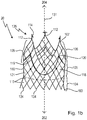
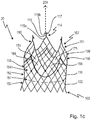
- Fig. 1A , 1B , and 1C show an exemplary embodiment of the prosthetic heart valve according to the invention, whereby Fig. 1A , 1B and 1C each show the same embodiment; due to clarity reasons, in the figures 1A , 1B and 1C not every feature described in the following description is shown in each of 1A, 1B and 1C, but rather the respective feature discussed for the respective figure.
- the prosthetic heart valve 20 has an expandable generally tubular stent support 102 forming a wire frame.
- the stent support 102 has a proximal end 103, a proximal portion 104, a medial portion 105, a distal portion 106, and a distal end 107.
- the stent support 102 also has an interior area 130, a longitudinal axis 131 extending from the proximal end 103 to the distal end 107, and a circumference 132.
- the proximal end 103 and the distal end 107 each comprises a crown with a plurality of free peaks 134, 112: At the proximal end 103, the peaks 134 are pointing in proximal direction 202, at the distal end, the peaks 112 are pointing in the distal direction 204.
- distal direction designates the direction in which the distal end 107 of the prosthetic heart valve 20 is pointing
- proximal direction designates the direction in which the proximal end 103 of the prosthetic heart valve is pointing.
- the tubular stent support further comprises a plurality of adjacent rows of interconnected diamond-shaped cell structures 110 extending between the proximal end 103 and distal end 107.
- the diamond shaped cell structures 110 may be, e.g. laser-cut or formed by interweaving or braiding metal, preferably Nitinol, wires.
- the diamond-shaped cell structures 110 are arranged in adjacent rows, where each of the diamond cell structures 110 is defined by a series of wires or wire segments of the wire frame formed by stent support 102: Due to the diamond shape of these cell structures 110, at least one "peak" of each diamond-shaped cell structure 110 of one row coincides with a "valley” created by two circumferentially adjacent diamond-shaped cell structures 110 in an adjacent row. Accordingly, a single row comprises multiple diamond-shaped cell structures 100 that are circumferentially adjacent to each other around the stent support 102.
- a row of diamond-shaped cell structures 110 adjacent to another row comprising multiple diamond-shaped structures 110 is a row that is located closest to, or interconnecting with, another row of diamond cell structures 110 along the longitudinal direction of the stent support 102.
- a “diamond” shaped cell structure as used herein is intended to generally mean the wire-segmented, four-sided cell shapes 110 in fig. 1 which comprise intersection points where two adjacent wires or wire segments meet.
- each diamond cell structure 110 has four intersection points, i.e. two intersection points that are spaced from each other along the longitudinal axis 131 of the stent support 102, which are referred to as "peaks" 133, 134 of one row (or which can be referred to as the "valleys" of an adjacent row).
- the diamond cell structures 110 further include two intersection points that are spaced from each other relative to the circumference 132 of the stent support 102.
- the stent support 102 comprises a crown 135 having three free peaks 112, i.e. three diamond-shaped cells 110 at the distal end 107 each have a free peak 112. Accordingly, the term “free” when used in connection with “peak” is meant to designate a peak or intersection point that is not connected or adjacent to or forming edges with another cell structure 110. As can also be seen in fig. 1 , all of the three of the free peaks 112 of the diamond shaped expandable cell structures 110 pointing in the distal direction have a connecting wire extension structure 114. In the embodiment shown, the connecting wire extension structure is T-shaped.
- the three connecting wire extension structures 114 present on the three free peaks 134 are used for attachment/connection to a delivery system, and are specifically configured to allow for removable attachment/connection of the stent support 102 relative to the delivery system.
- the embodiment of the prosthetic heart valve 10 as shown in the figures has a connecting wire extension structure 114 that is generally T-shaped.
- T-shaped any form or design of the free peak 112 of a cell structure 110 is meant, which has the shape of the letter "T”.
- the connecting wire extension structure 114 comprises a first wire extension section 115 that runs substantially parallel to the longitudinal axis 131 of the stent support 102, and another, a second wire extension section 117 that is substantially parallel to the circumference 132 of the stent support 102.
- the second wire extension section 117 can have any other form at least a portion of which is perpendicular to the longitudinal axis 131 of stent support 102, e.g. round or oval, or square.
- the first wire extension structure 115 has a first end 115a and a second end 115b. With its first end 115a, the connecting wire extension structure is attached to (or formed integrally with) one of the three free peaks/ends of 112 of stent support 102, while the other, a second end 115b, is coupled with/attached to or formed integrally with the second wire extension section 117.
- the medial portion 105 of the stent support 102 carries radiopaque markers 116, thus facilitating the orientation and placement of the prosthetic heart valve 20.
- the size of the cell structures 110 in the distal portion 106 of the stent support 102 is greater than the size of the cell structures 110 in the proximal portion 104 of the stent support 102.
- the prosthetic heart valve 20 also comprises a valve structure 118 having a plurality (i.e. three) of valve leaflets 119, and a plurality of valve commissure points 120.
- the valve structure 118 also comprises a valve skirt 121, which is attached to the stent support 102, such, that the valve structure 118 partially lines the inner area of the stent support 102, thus, forming, in the proximal portion 104, a sealing zone, wherein the inner area of the tubular stent support 102 is lined with the valve skirt 121.
- the material of the stent support 102 is preferably made from nitinol or any other metal with shape-memory characteristics.
- the valve may be a donor valve, e.g. a valve from a mammal, or an artificial valve.
- the valve structure 118 is, in a region 108 between the distal end 107 and the medial portion 105, and preferably in the distal portion 106 of the stent support 102, fixed to the stent support 102, namely via its commissure points 120.
- the stent support 102 has further, in a region 108 between the distal end 107 and the medial portion 105, a valve-free portion.
- commissure poles/points 120 are flexible and move inward during the closure of the valve.
- fig. 1A , 1B and 1C show that the prosthetic heart valve 20, in the region where the medial portion 105 transitions into the proximal portion 104, comprises a concave portion 160, i.e. a portion or section 160 where the tubular stent support 102 has a concave wall, i.e. a wall that is inwardly (relative to the tube-like structure) curved.
- This feature allows to better accommodate the calcium packages generally present in the native valve leaflets.
- the concave form of portion 160 can be achieved, e.g., by providing the stent support 102 in this portion with lesser expansion forces of the diamond-shaped cell structures 110 than diamond-shaped cell structures in other regions of the stent support 102.
- the lesser expansion force may be achieved by, e.g., cutting a stent structure from a nitinol tube having a certain length and thickness; in order to form the desired stent structure 102, the structure cut from the tube is thermally expanded by means of special tool mandrels until the desired diameter is reached; by using tool mandrels with different diameters, it is, thus, possible to generate areas or portions of the tube/stent structure 102 having different diameters.
- stent support 102 includes a series of adjacent rows of diamond-shaped cell structures 110.
- stent support 102 includes a first row 150 of such cell structures at the proximal end 103 of the stent support 102, which is, in longitudinal direction and towards the distal end, followed or adjacent to row 151 of diamond-shaped cell structures 110.
- Row 151 preferably comprises as many cell structures 110 as row 150; each of the structures of row 151 shares at least a portion of two wire segments with cell structures 110 of row 150.
- Row 151 is, in distal direction, followed by row 152 which preferably comprises as many cell structures 110 as row 151; each of the structures of row 152 shares at least a portion of two wire segments with cell structures 110 of row 151.
- Row 156 adjacent to row 154, then comprises less diamond-shaped cell structures 110, and, as a consequence, row 156 comprises cell structures 110 that are regarded as being neighbored in the same row that that do not touch each other; in other words, they are spaced from each other around the circumference of stent support 102. As a consequence, a "gap" is formed between cells 164 and 165 of row 156.
- row 156 not only comprises one gap, but three gaps, which are separated or spaced from each other in periodic distances: this is due to the fact that, also in periodic distances, row 156 is "missing" three diamond-shaped cell structures 110.
- row 158 being adjacent to row 156 towards the distal end 107 of the stent support 102, again comprises less diamond-shaped cell structures 110 than row 156, which feature, as a consequence, enlarges the gap between the cells 174, 175 of row 158 compared to the gap of row 156.
- the gap present in row 158 is adjacent to the gap of row 156, thus providing - together with the adjacent, subsequently larger getting gaps in the adjacent rows 159 and 161 - a terminal V-shaped opening in the circumference of stent support 102.
- each row 158, 159 and 161 also comprise not only one gap, but three gaps, which are separated or spaced from each other in periodic distances around the circumference of stent support 102 and which are adjacent to the gap in the previous, i.e. to the more proximal, row, thus enlarging the V or U-shaped openings in the wall or circumference 132 of stent support 102.
- the last row 190 at the distal end 107 of stent support 102 comprises, as can be seen from fig. 1A , 1B and 1C , only, i.e. solely or exclusively, three diamond-shaped cell structures 110, the peaks of which, respectively, form the distal crown 135 carrying the connecting wire extension structures 114.
- the stent support 102 of the prosthetic heart valve 20 has three V- or U-shaped openings which open towards the distal end 107.
- the three "V"s or "U”s formed in the circumference 132 of stent support towards the distal end 107 each represent a terminal opening in the circumference 132 of prosthetic heart valve 20 which are separated from one another through tail-like structures formed by the continuously reduced cell structures 110 in rows 156, 158, 159 and 160.
- Valve structure 118 is secured to via its commissure points or poles 120 to the stent support 102, such, that the commissure points 120 are located in the region of the tail-like structures.
- stent support 102 has a diameter that is smaller than the diameter compared to the diameter of the stent support 102 in other stent support portions.
Claims (13)
- Herzklappenprothese (20) zum Austausch einer nativen Klappe eines Patienten, wobei die Herzklappenprothese (20) umfasst:einen expandierbaren, im Allgemeinen rohrförmigen Stent-Träger (102), der einen Drahtrahmen bildet und ein proximales Ende (103), einen proximalen Abschnitt (104), einen mittleren Abschnitt (105), einen distalen Abschnitt (106) und ein distales Ende (107), einen Innenbereich, eine Längsachse (131), die vom proximalen Ende (103) zum distalen Ende (107) verläuft, und einen Umfang (132) aufweist, wobei das proximale Ende (103) und das distale Ende (107) jeweils eine Krone aus einer Vielzahl von freien Spitzen (112) umfassen, die jeweils in die proximale (202) und distale Richtung (204) zeigen, und wobei der rohrförmige Stent-Träger (102) eine Vielzahl von benachbarten Reihen (150, 151, 152, 154, 156, 158, 159, 161) von miteinander verbundenen rautenförmigen Zellstrukturen umfasst, die sich zwischen dem proximalen Ende (103) und dem distalen Ende (107) erstrecken,eine Klappenstruktur (118) mit einer Vielzahl von Klappensegeln, einer Klappenschürze (121) und einer Vielzahl von Klappenkommissurpunkten (120), und wobei die Klappenstruktur (118) innerhalb des Innenbereichs des Stent-Trägers (102) angebracht ist, so dass im proximalen Abschnitt (104) die Innenfläche des rohrförmigen Stent-Trägers (102) mit der Klappenstruktur (118) zur Ausbildung einer Dichtungszone ausgekleidet ist, dass ferner die Klappenstruktur (118) in einem Bereich (108) zwischen dem distalen Ende (107) und dem mittleren Abschnitt (105) über die Kommissurpunkte (120) an dem Stent-Träger (102) befestigt ist und dass der Sten-Träger (102) in einem Bereich (108) zwischen dem distalen Ende (107) und dem mittleren Abschnitt (105) einen klappenfreien Abschnitt aufweist,dadurch gekennzeichnet, dassdas distale Ende (107) des Stent-Trägers (102) in seiner Krone (135) nur drei freie Spitzen (112) aufweist, von denen alle Spitzen eine Verbindungsdrahtverlängerungsstruktur (114) aufweisen, wobei die Verbindungsdrahtverlängerungsstruktur einen ersten Drahtabschnitt (115) aufweist, der im Wesentlichen parallel zur Längsachse verläuft und eine im Allgemeinen longitudinale Form aufweist, die sich von distal nach proximal erstreckt, und einen zweiten Drahtabschnitt (117) aufweist, von dem sich mindestens ein Abschnitt in einer Richtung senkrecht zur Längsachse erstreckt.
- Herzklappenprothese (20) nach Anspruch 1, dadurch gekennzeichnet, dass die Herzklappenprothese (20) an ihrem distalen Ende (107) drei V- oder U-förmige Öffnungen in ihrem Umfang (32) aufweist, wobei sich die V- oder U-förmige Öffnungen zum distalen Ende (107) des Stent-Trägers (102) öffnen.
- Herzklappenprothese (20) nach Anspruch 1 oder 2, dadurch gekennzeichnet, dass eine rautenförmige Zellstruktur (110) aus zwei Schnittpunkten gebildet ist, die entlang der Längsachse (131) des Stent-Trägers (102) voneinander beabstandet sind und die Spitzen (134) einer Reihe (150, 151, 152, 154, 156, 158, 159, 161) bilden, und von zwei Schnittpunkten, die relativ zum Umfang des Stent-Trägers voneinander beabstandet sind, wobei die letzte Reihe am distalen Ende (107) nur drei rautenförmige Zellstrukturen (110) umfasst, die um den Umfang des Stent-Trägers (102) herum voneinander beabstandet sind, so dass sie sich nicht berühren.
- Herzklappenprothese (20) nach Anspruch 3, dadurch gekennzeichnet, dass die der letzten Reihe (161) benachbarte Reihe (159) am proximalen Ende (107) mehr rautenförmige Zellstrukturen (110) umfasst als die letzte Reihe des distalen Endes (107), wobei einige der Zellstrukturen (110) um den Umfang (132) des Stent-Trägers (102) voneinander beabstandet sind und wobei einige der Zellstrukturen (110) einander berühren.
- Herzklappenprothese (20) nach Anspruch 4, dadurch gekennzeichnet, dass die vorletzte Reihe (159) am distalen Ende (107), die an die letzte Reihe (161) am distalen Ende (107) angrenzt, sechs rautenförmige Zellstrukturen (110) umfasst, wobei zwei Zellstrukturen (110) sich jeweils berühren und so Zellstrukturpaare bilden, wobei die Zellstrukturpaare um den Umfang (132) des Stent-Trägers (102) voneinander beabstandet sind.
- Herzklappenprothese (20) nach einem der Ansprüche 3 bis 5, dadurch gekennzeichnet, dass die in proximaler Richtung (202) an die vorletzte Reihe (159) des distalen Endes (107) angrenzende Reihe (158) mehr rautenförmige Zellstrukturen (110) umfasst als die vorletzte Reihe (159) am distalen Ende (107).
- Herzklappenprothese (20) nach einem der vorhergehenden Ansprüche, dadurch gekennzeichnet, dass im mittleren Abschnitt (105) des Stent-Trägers (102) röntgendichte Marker (116) vorgesehen sind.
- Herzklappenprothese (20) nach einem der vorhergehenden Ansprüche, dadurch gekennzeichnet, dass am distalen Ende (107) die Rohrform des Stent-Trägers (102) im klappenfreien Abschnitt einen Durchmesser aufweist, der gegenüber der verbleibenden Rohrform des Stent-Trägers (102) reduziert ist.
- Herzklappenprothese (20) nach einem der vorhergehenden Ansprüche, dadurch gekennzeichnet, dass an der Befestigungsstelle der Kommissurpunkte (120) der Klappenstruktur (100) am Stent-Träger (102) die Rohrform des Stent-Trägers (102) flexibel (114) ist.
- Herzklappenprothese (20) nach einem der vorhergehenden Ansprüche, dadurch gekennzeichnet, dass die Verbindungsdrahtverlängerungsstruktur (114) einen ersten Drahtabschnitt (115) mit einem ersten Ende (115a) und einem zweiten Ende (115b) aufweist und im Wesentlichen parallel zur Längsachse (131) des Stent-Trägers (102) verläuft, und einen zweiten Drahtabschnitt (117), der am zweiten Ende (115b) des ersten Drahtabschnitts (115) angeordnet ist.
- Herzklappenprothese (20) nach einem der vorhergehenden Ansprüche, dadurch gekennzeichnet, dass der zweite Abschnitt (117) eine Form aufweist, die aus im Wesentlichen rund, oval, quadratisch oder länglich ausgewählt ist.
- Herzklappenprothese (20) nach einem der vorhergehenden Ansprüche, dadurch gekennzeichnet, dass die Verbindungsdrahtverlängerungsstruktur (114) T-förmig ist.
- Herzklappenprothese (20) nach einem der vorhergehenden Ansprüche, dadurch gekennzeichnet, dass die Herzklappenprothese (20) in dem Bereich, in dem der mittlere Abschnitt (105) in den proximalen Abschnitt (104) übergeht, einen Bereich (160) umfasst, der in Bezug auf die Längsachse (131) des Stent-Trägers (102) konkav ist.
Priority Applications (6)
| Application Number | Priority Date | Filing Date | Title |
|---|---|---|---|
| ES14160492T ES2711663T3 (es) | 2014-03-18 | 2014-03-18 | Implante de válvula cardiaca |
| EP14160492.6A EP2921139B1 (de) | 2014-03-18 | 2014-03-18 | Herzklappenimplantat |
| JP2015037698A JP6546751B2 (ja) | 2014-03-18 | 2015-02-27 | 移植用心臓弁 |
| CN201510111484.1A CN104921843A (zh) | 2014-03-18 | 2015-03-13 | 心瓣植入物 |
| CN202011437843.XA CN112603596A (zh) | 2014-03-18 | 2015-03-13 | 心瓣植入物 |
| US14/660,065 US9474604B2 (en) | 2014-03-18 | 2015-03-17 | Heartvalve implant |
Applications Claiming Priority (1)
| Application Number | Priority Date | Filing Date | Title |
|---|---|---|---|
| EP14160492.6A EP2921139B1 (de) | 2014-03-18 | 2014-03-18 | Herzklappenimplantat |
Publications (2)
| Publication Number | Publication Date |
|---|---|
| EP2921139A1 EP2921139A1 (de) | 2015-09-23 |
| EP2921139B1 true EP2921139B1 (de) | 2018-11-21 |
Family
ID=50289503
Family Applications (1)
| Application Number | Title | Priority Date | Filing Date |
|---|---|---|---|
| EP14160492.6A Active EP2921139B1 (de) | 2014-03-18 | 2014-03-18 | Herzklappenimplantat |
Country Status (5)
| Country | Link |
|---|---|
| US (1) | US9474604B2 (de) |
| EP (1) | EP2921139B1 (de) |
| JP (1) | JP6546751B2 (de) |
| CN (2) | CN112603596A (de) |
| ES (1) | ES2711663T3 (de) |
Cited By (13)
| Publication number | Priority date | Publication date | Assignee | Title |
|---|---|---|---|---|
| US10856984B2 (en) | 2017-08-25 | 2020-12-08 | Neovasc Tiara Inc. | Sequentially deployed transcatheter mitral valve prosthesis |
| US10940001B2 (en) | 2012-05-30 | 2021-03-09 | Neovasc Tiara Inc. | Methods and apparatus for loading a prosthesis onto a delivery system |
| US11311376B2 (en) | 2019-06-20 | 2022-04-26 | Neovase Tiara Inc. | Low profile prosthetic mitral valve |
| US11357622B2 (en) | 2016-01-29 | 2022-06-14 | Neovase Tiara Inc. | Prosthetic valve for avoiding obstruction of outflow |
| US11389291B2 (en) | 2013-04-04 | 2022-07-19 | Neovase Tiara Inc. | Methods and apparatus for delivering a prosthetic valve to a beating heart |
| US11413139B2 (en) | 2011-11-23 | 2022-08-16 | Neovasc Tiara Inc. | Sequentially deployed transcatheter mitral valve prosthesis |
| US11419720B2 (en) | 2010-05-05 | 2022-08-23 | Neovasc Tiara Inc. | Transcatheter mitral valve prosthesis |
| US11464631B2 (en) | 2016-11-21 | 2022-10-11 | Neovasc Tiara Inc. | Methods and systems for rapid retraction of a transcatheter heart valve delivery system |
| US11491006B2 (en) | 2019-04-10 | 2022-11-08 | Neovasc Tiara Inc. | Prosthetic valve with natural blood flow |
| US11497602B2 (en) | 2012-02-14 | 2022-11-15 | Neovasc Tiara Inc. | Methods and apparatus for engaging a valve prosthesis with tissue |
| US11602429B2 (en) | 2019-04-01 | 2023-03-14 | Neovasc Tiara Inc. | Controllably deployable prosthetic valve |
| US11737872B2 (en) | 2018-11-08 | 2023-08-29 | Neovasc Tiara Inc. | Ventricular deployment of a transcatheter mitral valve prosthesis |
| US11779742B2 (en) | 2019-05-20 | 2023-10-10 | Neovasc Tiara Inc. | Introducer with hemostasis mechanism |
Families Citing this family (43)
| Publication number | Priority date | Publication date | Assignee | Title |
|---|---|---|---|---|
| US9572660B2 (en) | 2007-06-04 | 2017-02-21 | St. Jude Medical, Inc. | Prosthetic heart valves |
| US9011515B2 (en) | 2012-04-19 | 2015-04-21 | Caisson Interventional, LLC | Heart valve assembly systems and methods |
| US9427315B2 (en) | 2012-04-19 | 2016-08-30 | Caisson Interventional, LLC | Valve replacement systems and methods |
| US9050188B2 (en) | 2013-10-23 | 2015-06-09 | Caisson Interventional, LLC | Methods and systems for heart valve therapy |
| US10098734B2 (en) * | 2013-12-05 | 2018-10-16 | Edwards Lifesciences Corporation | Prosthetic heart valve and delivery apparatus |
| US9974647B2 (en) | 2014-06-12 | 2018-05-22 | Caisson Interventional, LLC | Two stage anchor and mitral valve assembly |
| US9750607B2 (en) | 2014-10-23 | 2017-09-05 | Caisson Interventional, LLC | Systems and methods for heart valve therapy |
| US9750605B2 (en) | 2014-10-23 | 2017-09-05 | Caisson Interventional, LLC | Systems and methods for heart valve therapy |
| AU2016233216B2 (en) | 2015-03-19 | 2020-08-20 | Caisson Interventional, LLC | Systems and methods for heart valve therapy |
| US10350066B2 (en) | 2015-08-28 | 2019-07-16 | Edwards Lifesciences Cardiaq Llc | Steerable delivery system for replacement mitral valve and methods of use |
| EP3960127A1 (de) | 2015-12-30 | 2022-03-02 | Caisson Interventional, LLC | Systeme und verfahren für die herzklappentherapie |
| US10350062B2 (en) * | 2016-07-21 | 2019-07-16 | Edwards Lifesciences Corporation | Replacement heart valve prosthesis |
| WO2018080328A1 (en) | 2016-10-19 | 2018-05-03 | Chodor Piotr | Stent of aortic valve implanted transcatheterly |
| DE202016105963U1 (de) | 2016-10-24 | 2018-01-25 | Nvt Ag | Intraluminale Gefäßprothese zur Implantation in das Herz oder Herzgefäße eines Patienten |
| US10653523B2 (en) | 2017-01-19 | 2020-05-19 | 4C Medical Technologies, Inc. | Systems, methods and devices for delivery systems, methods and devices for implanting prosthetic heart valves |
| US10561495B2 (en) | 2017-01-24 | 2020-02-18 | 4C Medical Technologies, Inc. | Systems, methods and devices for two-step delivery and implantation of prosthetic heart valve |
| EP3585312A4 (de) * | 2017-02-27 | 2020-12-02 | Dura LLC | Neuartige transkatheterventilaustauschvorrichtung |
| WO2018184226A1 (zh) * | 2017-04-07 | 2018-10-11 | 上海甲悦医疗器械有限公司 | 一种人工瓣膜及人工瓣膜植入方法 |
| CN109984868A (zh) * | 2017-12-30 | 2019-07-09 | 上海微创心通医疗科技有限公司 | 心脏瓣膜假体和输送器 |
| CN111818877B (zh) | 2018-01-25 | 2023-12-22 | 爱德华兹生命科学公司 | 在部署后用于辅助置换瓣膜重新捕获和重新定位的递送系统 |
| EP3761907A1 (de) * | 2018-03-08 | 2021-01-13 | Symetis SA | Implantierbares ventil mit befestigten polymerkomponenten |
| WO2019195860A2 (en) | 2018-04-04 | 2019-10-10 | Vdyne, Llc | Devices and methods for anchoring transcatheter heart valve |
| US11857441B2 (en) | 2018-09-04 | 2024-01-02 | 4C Medical Technologies, Inc. | Stent loading device |
| US11278437B2 (en) | 2018-12-08 | 2022-03-22 | Vdyne, Inc. | Compression capable annular frames for side delivery of transcatheter heart valve replacement |
| US10321995B1 (en) | 2018-09-20 | 2019-06-18 | Vdyne, Llc | Orthogonally delivered transcatheter heart valve replacement |
| US11071627B2 (en) | 2018-10-18 | 2021-07-27 | Vdyne, Inc. | Orthogonally delivered transcatheter heart valve frame for valve in valve prosthesis |
| US11344413B2 (en) | 2018-09-20 | 2022-05-31 | Vdyne, Inc. | Transcatheter deliverable prosthetic heart valves and methods of delivery |
| US10595994B1 (en) | 2018-09-20 | 2020-03-24 | Vdyne, Llc | Side-delivered transcatheter heart valve replacement |
| US11109969B2 (en) | 2018-10-22 | 2021-09-07 | Vdyne, Inc. | Guidewire delivery of transcatheter heart valve |
| US11253359B2 (en) | 2018-12-20 | 2022-02-22 | Vdyne, Inc. | Proximal tab for side-delivered transcatheter heart valves and methods of delivery |
| US10653522B1 (en) | 2018-12-20 | 2020-05-19 | Vdyne, Inc. | Proximal tab for side-delivered transcatheter heart valve prosthesis |
| US11273032B2 (en) | 2019-01-26 | 2022-03-15 | Vdyne, Inc. | Collapsible inner flow control component for side-deliverable transcatheter heart valve prosthesis |
| US11185409B2 (en) | 2019-01-26 | 2021-11-30 | Vdyne, Inc. | Collapsible inner flow control component for side-delivered transcatheter heart valve prosthesis |
| AU2020231221A1 (en) | 2019-03-05 | 2021-09-23 | Vdyne, Inc. | Tricuspid regurgitation control devices for orthogonal transcatheter heart valve prosthesis |
| US11173027B2 (en) | 2019-03-14 | 2021-11-16 | Vdyne, Inc. | Side-deliverable transcatheter prosthetic valves and methods for delivering and anchoring the same |
| US10758346B1 (en) | 2019-03-14 | 2020-09-01 | Vdyne, Inc. | A2 clip for side-delivered transcatheter mitral valve prosthesis |
| US11076956B2 (en) | 2019-03-14 | 2021-08-03 | Vdyne, Inc. | Proximal, distal, and anterior anchoring tabs for side-delivered transcatheter mitral valve prosthesis |
| US10631983B1 (en) | 2019-03-14 | 2020-04-28 | Vdyne, Inc. | Distal subannular anchoring tab for side-delivered transcatheter valve prosthesis |
| EP3965701A4 (de) | 2019-05-04 | 2023-02-15 | Vdyne, Inc. | Cinchvorrichtung und verfahren zum einsatz einer seitlich freigesetzten herzklappenprothese in einem nativen ring |
| CA3152042A1 (en) | 2019-08-20 | 2021-02-25 | Vdyne, Inc. | Delivery and retrieval devices and methods for side-deliverable transcatheter prosthetic valves |
| AU2020337235A1 (en) | 2019-08-26 | 2022-03-24 | Vdyne, Inc. | Side-deliverable transcatheter prosthetic valves and methods for delivering and anchoring the same |
| US11234813B2 (en) | 2020-01-17 | 2022-02-01 | Vdyne, Inc. | Ventricular stability elements for side-deliverable prosthetic heart valves and methods of delivery |
| US11931253B2 (en) | 2020-01-31 | 2024-03-19 | 4C Medical Technologies, Inc. | Prosthetic heart valve delivery system: ball-slide attachment |
Family Cites Families (42)
| Publication number | Priority date | Publication date | Assignee | Title |
|---|---|---|---|---|
| US5843167A (en) * | 1993-04-22 | 1998-12-01 | C. R. Bard, Inc. | Method and apparatus for recapture of hooked endoprosthesis |
| ES2135520T3 (es) * | 1993-11-04 | 1999-11-01 | Bard Inc C R | Protesis vascular no migrante. |
| EP0850607A1 (de) * | 1996-12-31 | 1998-07-01 | Cordis Corporation | Klappenprothese zur Implantation in Körperkanälen |
| US7452371B2 (en) * | 1999-06-02 | 2008-11-18 | Cook Incorporated | Implantable vascular device |
| EP1584307A3 (de) * | 1999-04-23 | 2005-10-19 | St.Jude Medical ATG, Inc. | Künstliche Herzklappe mit Befestigungsfingern |
| US7628803B2 (en) * | 2001-02-05 | 2009-12-08 | Cook Incorporated | Implantable vascular device |
| US6440164B1 (en) * | 1999-10-21 | 2002-08-27 | Scimed Life Systems, Inc. | Implantable prosthetic valve |
| US7195641B2 (en) * | 1999-11-19 | 2007-03-27 | Advanced Bio Prosthetic Surfaces, Ltd. | Valvular prostheses having metal or pseudometallic construction and methods of manufacture |
| US6458153B1 (en) * | 1999-12-31 | 2002-10-01 | Abps Venture One, Ltd. | Endoluminal cardiac and venous valve prostheses and methods of manufacture and delivery thereof |
| WO2002022054A1 (en) * | 2000-09-12 | 2002-03-21 | Gabbay S | Valvular prosthesis and method of using same |
| FR2828091B1 (fr) * | 2001-07-31 | 2003-11-21 | Seguin Jacques | Ensemble permettant la mise en place d'une valve prothetique dans un conduit corporel |
| WO2004089253A1 (en) * | 2003-04-01 | 2004-10-21 | Cook Incorporated | Percutaneously deployed vascular valves |
| DE602004023708D1 (de) * | 2003-04-24 | 2009-12-03 | Cook Inc | Künstliche klappe für blutgefäss mit verbessertem fliessverhalten |
| US7717952B2 (en) * | 2003-04-24 | 2010-05-18 | Cook Incorporated | Artificial prostheses with preferred geometries |
| US7201772B2 (en) * | 2003-07-08 | 2007-04-10 | Ventor Technologies, Ltd. | Fluid flow prosthetic device |
| US20060259137A1 (en) * | 2003-10-06 | 2006-11-16 | Jason Artof | Minimally invasive valve replacement system |
| US8343213B2 (en) * | 2003-12-23 | 2013-01-01 | Sadra Medical, Inc. | Leaflet engagement elements and methods for use thereof |
| US7566343B2 (en) * | 2004-09-02 | 2009-07-28 | Boston Scientific Scimed, Inc. | Cardiac valve, system, and method |
| EP1863545B1 (de) * | 2005-03-19 | 2015-11-18 | Cook Biotech, Inc. | Prothetische Implantate mit ECM-Verbundwerkstoff |
| US7914569B2 (en) * | 2005-05-13 | 2011-03-29 | Medtronics Corevalve Llc | Heart valve prosthesis and methods of manufacture and use |
| EP1895941A1 (de) * | 2005-05-20 | 2008-03-12 | The Cleveland Clinic Foundation | Geräte und verfahren zur wiederherstellung der funktion einer erkrankten klappe und herstellungsverfahren dafür |
| WO2007058857A2 (en) * | 2005-11-10 | 2007-05-24 | Arshad Quadri | Balloon-expandable, self-expanding, vascular prosthesis connecting stent |
| US8303648B2 (en) * | 2006-04-25 | 2012-11-06 | Cook Medical Technologies Llc | Artificial venous valve containing therapeutic agent |
| AU2007255072A1 (en) * | 2006-05-30 | 2007-12-13 | Cook Incorporated | Artificial valve prosthesis |
| US8257429B2 (en) * | 2006-08-21 | 2012-09-04 | Oregon Health & Science University | Biomedical valve devices, support frames for use in such devices, and related methods |
| US8348995B2 (en) * | 2006-09-19 | 2013-01-08 | Medtronic Ventor Technologies, Ltd. | Axial-force fixation member for valve |
| US7896915B2 (en) * | 2007-04-13 | 2011-03-01 | Jenavalve Technology, Inc. | Medical device for treating a heart valve insufficiency |
| AU2007351026B2 (en) * | 2007-04-13 | 2012-04-05 | Jenavalve Technology Inc. | Medical device for treating a heart valve insufficiency or stenosis |
| EP1980220A1 (de) * | 2007-04-13 | 2008-10-15 | JenaValve Technology GmbH | Medizinische Vorrichtung zur Behandlung einer Herzklappeninsuffizienz oder Stenose |
| US9138315B2 (en) * | 2007-04-13 | 2015-09-22 | Jenavalve Technology Gmbh | Medical device for treating a heart valve insufficiency or stenosis |
| EP3150171A1 (de) * | 2007-05-15 | 2017-04-05 | JenaValve Technology, Inc. | Handgriff zur manipulation einer katheterspitze, kathetersystem und medizinisches einführungssystem zur einführung eines selbstexpandierenden herzklappenstents |
| CN102119013B (zh) * | 2008-07-17 | 2014-12-03 | Nvt股份公司 | 心脏瓣膜假体系统 |
| CN101352376A (zh) * | 2008-09-02 | 2009-01-28 | 中国人民解放军第二军医大学 | 带锚定脚的主动脉瓣膜支架 |
| US8449599B2 (en) * | 2009-12-04 | 2013-05-28 | Edwards Lifesciences Corporation | Prosthetic valve for replacing mitral valve |
| US9480557B2 (en) * | 2010-03-25 | 2016-11-01 | Medtronic, Inc. | Stents for prosthetic heart valves |
| US8465541B2 (en) * | 2010-04-19 | 2013-06-18 | Medtronic, Inc. | Transcatheter prosthetic heart valve delivery system and method with expandable stability tube |
| US8623079B2 (en) * | 2010-04-23 | 2014-01-07 | Medtronic, Inc. | Stents for prosthetic heart valves |
| EP2563278B1 (de) * | 2010-04-27 | 2018-07-11 | Medtronic, Inc. | Vorrichtung zur transkatheter-freisetzung einer herzklappenprothese mit vorgespannten lösevorrichtungen |
| US20120116498A1 (en) * | 2010-11-05 | 2012-05-10 | Chuter Timothy A | Aortic valve prostheses |
| EP2520251A1 (de) * | 2011-05-05 | 2012-11-07 | Symetis SA | Verfahren und Vorrichtung zum Zusammendrücken von Stentklappen |
| CN102764169B (zh) * | 2012-04-19 | 2015-07-29 | 杭州启明医疗器械有限公司 | 人工心脏瓣膜及其瓣膜支架 |
| US9918837B2 (en) * | 2012-06-29 | 2018-03-20 | St. Jude Medical, Cardiology Division, Inc. | System to assist in the release of a collapsible stent from a delivery device |
-
2014
- 2014-03-18 ES ES14160492T patent/ES2711663T3/es active Active
- 2014-03-18 EP EP14160492.6A patent/EP2921139B1/de active Active
-
2015
- 2015-02-27 JP JP2015037698A patent/JP6546751B2/ja active Active
- 2015-03-13 CN CN202011437843.XA patent/CN112603596A/zh active Pending
- 2015-03-13 CN CN201510111484.1A patent/CN104921843A/zh active Pending
- 2015-03-17 US US14/660,065 patent/US9474604B2/en active Active
Non-Patent Citations (1)
| Title |
|---|
| None * |
Cited By (17)
| Publication number | Priority date | Publication date | Assignee | Title |
|---|---|---|---|---|
| US11419720B2 (en) | 2010-05-05 | 2022-08-23 | Neovasc Tiara Inc. | Transcatheter mitral valve prosthesis |
| US11413139B2 (en) | 2011-11-23 | 2022-08-16 | Neovasc Tiara Inc. | Sequentially deployed transcatheter mitral valve prosthesis |
| US11497602B2 (en) | 2012-02-14 | 2022-11-15 | Neovasc Tiara Inc. | Methods and apparatus for engaging a valve prosthesis with tissue |
| US11617650B2 (en) | 2012-05-30 | 2023-04-04 | Neovasc Tiara Inc. | Methods and apparatus for loading a prosthesis onto a delivery system |
| US11389294B2 (en) | 2012-05-30 | 2022-07-19 | Neovasc Tiara Inc. | Methods and apparatus for loading a prosthesis onto a delivery system |
| US10940001B2 (en) | 2012-05-30 | 2021-03-09 | Neovasc Tiara Inc. | Methods and apparatus for loading a prosthesis onto a delivery system |
| US11389291B2 (en) | 2013-04-04 | 2022-07-19 | Neovase Tiara Inc. | Methods and apparatus for delivering a prosthetic valve to a beating heart |
| US11357622B2 (en) | 2016-01-29 | 2022-06-14 | Neovase Tiara Inc. | Prosthetic valve for avoiding obstruction of outflow |
| US11464631B2 (en) | 2016-11-21 | 2022-10-11 | Neovasc Tiara Inc. | Methods and systems for rapid retraction of a transcatheter heart valve delivery system |
| US10856984B2 (en) | 2017-08-25 | 2020-12-08 | Neovasc Tiara Inc. | Sequentially deployed transcatheter mitral valve prosthesis |
| US11793640B2 (en) | 2017-08-25 | 2023-10-24 | Neovasc Tiara Inc. | Sequentially deployed transcatheter mitral valve prosthesis |
| US11737872B2 (en) | 2018-11-08 | 2023-08-29 | Neovasc Tiara Inc. | Ventricular deployment of a transcatheter mitral valve prosthesis |
| US11602429B2 (en) | 2019-04-01 | 2023-03-14 | Neovasc Tiara Inc. | Controllably deployable prosthetic valve |
| US11491006B2 (en) | 2019-04-10 | 2022-11-08 | Neovasc Tiara Inc. | Prosthetic valve with natural blood flow |
| US11779742B2 (en) | 2019-05-20 | 2023-10-10 | Neovasc Tiara Inc. | Introducer with hemostasis mechanism |
| US11311376B2 (en) | 2019-06-20 | 2022-04-26 | Neovase Tiara Inc. | Low profile prosthetic mitral valve |
| US11931254B2 (en) | 2019-06-20 | 2024-03-19 | Neovasc Tiara Inc. | Low profile prosthetic mitral valve |
Also Published As
| Publication number | Publication date |
|---|---|
| CN104921843A (zh) | 2015-09-23 |
| JP6546751B2 (ja) | 2019-07-17 |
| EP2921139A1 (de) | 2015-09-23 |
| ES2711663T3 (es) | 2019-05-06 |
| JP2015177971A (ja) | 2015-10-08 |
| US9474604B2 (en) | 2016-10-25 |
| US20150265402A1 (en) | 2015-09-24 |
| CN112603596A (zh) | 2021-04-06 |
Similar Documents
| Publication | Publication Date | Title |
|---|---|---|
| EP2921139B1 (de) | Herzklappenimplantat | |
| US10512539B2 (en) | Prosthetic heart valve system and delivery system therefor | |
| US10433957B2 (en) | Stent cell bridge for cuff attachment | |
| US20230270542A1 (en) | Bowed Runners for Paravalvular Leak Protection | |
| US10321993B2 (en) | Self-expanding heart valves for coronary perfusion and sealing | |
| US9687341B2 (en) | Self-actuating sealing portions for paravalvular leak protection | |
| EP1926455B1 (de) | Vorrichtung für endovaskulären Herzklappenersatz mit Gewebegreifelementen | |
| EP3572045B1 (de) | Stents für herzklappenprothesen | |
| EP2929860A1 (de) | Vorrichtung zur Implantation im Herz eines Säugers | |
| CN113164254B (zh) | 人工瓣膜递送组件 | |
| US20150057747A1 (en) | Stent with alternative cell shapes | |
| EP3988052A1 (de) | Passive ausrichtung von kommissuren bei der implantation von herzklappenprothesen | |
| CN114191146A (zh) | 一种瓣膜支架和包括其的人工瓣膜装置 | |
| WO2023183270A1 (en) | Mechanically expandable prosthetic heart valve | |
| BR102015029539B1 (pt) | Sistema de válvula cardíaca protética e sistema de entrega para a mesma |
Legal Events
| Date | Code | Title | Description |
|---|---|---|---|
| PUAI | Public reference made under article 153(3) epc to a published international application that has entered the european phase |
Free format text: ORIGINAL CODE: 0009012 |
|
| AK | Designated contracting states |
Kind code of ref document: A1 Designated state(s): AL AT BE BG CH CY CZ DE DK EE ES FI FR GB GR HR HU IE IS IT LI LT LU LV MC MK MT NL NO PL PT RO RS SE SI SK SM TR |
|
| AX | Request for extension of the european patent |
Extension state: BA ME |
|
| 17P | Request for examination filed |
Effective date: 20160322 |
|
| RBV | Designated contracting states (corrected) |
Designated state(s): AL AT BE BG CH CY CZ DE DK EE ES FI FR GB GR HR HU IE IS IT LI LT LU LV MC MK MT NL NO PL PT RO RS SE SI SK SM TR |
|
| GRAP | Despatch of communication of intention to grant a patent |
Free format text: ORIGINAL CODE: EPIDOSNIGR1 |
|
| STAA | Information on the status of an ep patent application or granted ep patent |
Free format text: STATUS: GRANT OF PATENT IS INTENDED |
|
| INTG | Intention to grant announced |
Effective date: 20180601 |
|
| GRAS | Grant fee paid |
Free format text: ORIGINAL CODE: EPIDOSNIGR3 |
|
| GRAA | (expected) grant |
Free format text: ORIGINAL CODE: 0009210 |
|
| STAA | Information on the status of an ep patent application or granted ep patent |
Free format text: STATUS: THE PATENT HAS BEEN GRANTED |
|
| AK | Designated contracting states |
Kind code of ref document: B1 Designated state(s): AL AT BE BG CH CY CZ DE DK EE ES FI FR GB GR HR HU IE IS IT LI LT LU LV MC MK MT NL NO PL PT RO RS SE SI SK SM TR |
|
| REG | Reference to a national code |
Ref country code: CH Ref legal event code: EP |
|
| REG | Reference to a national code |
Ref country code: IE Ref legal event code: FG4D |
|
| REG | Reference to a national code |
Ref country code: DE Ref legal event code: R096 Ref document number: 602014036325 Country of ref document: DE |
|
| REG | Reference to a national code |
Ref country code: AT Ref legal event code: REF Ref document number: 1066648 Country of ref document: AT Kind code of ref document: T Effective date: 20181215 |
|
| REG | Reference to a national code |
Ref country code: NL Ref legal event code: MP Effective date: 20181121 |
|
| REG | Reference to a national code |
Ref country code: AT Ref legal event code: MK05 Ref document number: 1066648 Country of ref document: AT Kind code of ref document: T Effective date: 20181121 |
|
| PG25 | Lapsed in a contracting state [announced via postgrant information from national office to epo] |
Ref country code: NO Free format text: LAPSE BECAUSE OF FAILURE TO SUBMIT A TRANSLATION OF THE DESCRIPTION OR TO PAY THE FEE WITHIN THE PRESCRIBED TIME-LIMIT Effective date: 20190221 Ref country code: IS Free format text: LAPSE BECAUSE OF FAILURE TO SUBMIT A TRANSLATION OF THE DESCRIPTION OR TO PAY THE FEE WITHIN THE PRESCRIBED TIME-LIMIT Effective date: 20190321 Ref country code: AT Free format text: LAPSE BECAUSE OF FAILURE TO SUBMIT A TRANSLATION OF THE DESCRIPTION OR TO PAY THE FEE WITHIN THE PRESCRIBED TIME-LIMIT Effective date: 20181121 Ref country code: HR Free format text: LAPSE BECAUSE OF FAILURE TO SUBMIT A TRANSLATION OF THE DESCRIPTION OR TO PAY THE FEE WITHIN THE PRESCRIBED TIME-LIMIT Effective date: 20181121 Ref country code: LT Free format text: LAPSE BECAUSE OF FAILURE TO SUBMIT A TRANSLATION OF THE DESCRIPTION OR TO PAY THE FEE WITHIN THE PRESCRIBED TIME-LIMIT Effective date: 20181121 Ref country code: BG Free format text: LAPSE BECAUSE OF FAILURE TO SUBMIT A TRANSLATION OF THE DESCRIPTION OR TO PAY THE FEE WITHIN THE PRESCRIBED TIME-LIMIT Effective date: 20190221 Ref country code: FI Free format text: LAPSE BECAUSE OF FAILURE TO SUBMIT A TRANSLATION OF THE DESCRIPTION OR TO PAY THE FEE WITHIN THE PRESCRIBED TIME-LIMIT Effective date: 20181121 Ref country code: LV Free format text: LAPSE BECAUSE OF FAILURE TO SUBMIT A TRANSLATION OF THE DESCRIPTION OR TO PAY THE FEE WITHIN THE PRESCRIBED TIME-LIMIT Effective date: 20181121 |
|
| REG | Reference to a national code |
Ref country code: ES Ref legal event code: FG2A Ref document number: 2711663 Country of ref document: ES Kind code of ref document: T3 Effective date: 20190506 |
|
| PG25 | Lapsed in a contracting state [announced via postgrant information from national office to epo] |
Ref country code: AL Free format text: LAPSE BECAUSE OF FAILURE TO SUBMIT A TRANSLATION OF THE DESCRIPTION OR TO PAY THE FEE WITHIN THE PRESCRIBED TIME-LIMIT Effective date: 20181121 Ref country code: RS Free format text: LAPSE BECAUSE OF FAILURE TO SUBMIT A TRANSLATION OF THE DESCRIPTION OR TO PAY THE FEE WITHIN THE PRESCRIBED TIME-LIMIT Effective date: 20181121 Ref country code: SE Free format text: LAPSE BECAUSE OF FAILURE TO SUBMIT A TRANSLATION OF THE DESCRIPTION OR TO PAY THE FEE WITHIN THE PRESCRIBED TIME-LIMIT Effective date: 20181121 Ref country code: NL Free format text: LAPSE BECAUSE OF FAILURE TO SUBMIT A TRANSLATION OF THE DESCRIPTION OR TO PAY THE FEE WITHIN THE PRESCRIBED TIME-LIMIT Effective date: 20181121 Ref country code: GR Free format text: LAPSE BECAUSE OF FAILURE TO SUBMIT A TRANSLATION OF THE DESCRIPTION OR TO PAY THE FEE WITHIN THE PRESCRIBED TIME-LIMIT Effective date: 20190222 Ref country code: PT Free format text: LAPSE BECAUSE OF FAILURE TO SUBMIT A TRANSLATION OF THE DESCRIPTION OR TO PAY THE FEE WITHIN THE PRESCRIBED TIME-LIMIT Effective date: 20190321 |
|
| PG25 | Lapsed in a contracting state [announced via postgrant information from national office to epo] |
Ref country code: CZ Free format text: LAPSE BECAUSE OF FAILURE TO SUBMIT A TRANSLATION OF THE DESCRIPTION OR TO PAY THE FEE WITHIN THE PRESCRIBED TIME-LIMIT Effective date: 20181121 Ref country code: DK Free format text: LAPSE BECAUSE OF FAILURE TO SUBMIT A TRANSLATION OF THE DESCRIPTION OR TO PAY THE FEE WITHIN THE PRESCRIBED TIME-LIMIT Effective date: 20181121 Ref country code: PL Free format text: LAPSE BECAUSE OF FAILURE TO SUBMIT A TRANSLATION OF THE DESCRIPTION OR TO PAY THE FEE WITHIN THE PRESCRIBED TIME-LIMIT Effective date: 20181121 |
|
| REG | Reference to a national code |
Ref country code: DE Ref legal event code: R097 Ref document number: 602014036325 Country of ref document: DE |
|
| PG25 | Lapsed in a contracting state [announced via postgrant information from national office to epo] |
Ref country code: EE Free format text: LAPSE BECAUSE OF FAILURE TO SUBMIT A TRANSLATION OF THE DESCRIPTION OR TO PAY THE FEE WITHIN THE PRESCRIBED TIME-LIMIT Effective date: 20181121 Ref country code: SM Free format text: LAPSE BECAUSE OF FAILURE TO SUBMIT A TRANSLATION OF THE DESCRIPTION OR TO PAY THE FEE WITHIN THE PRESCRIBED TIME-LIMIT Effective date: 20181121 Ref country code: RO Free format text: LAPSE BECAUSE OF FAILURE TO SUBMIT A TRANSLATION OF THE DESCRIPTION OR TO PAY THE FEE WITHIN THE PRESCRIBED TIME-LIMIT Effective date: 20181121 Ref country code: SK Free format text: LAPSE BECAUSE OF FAILURE TO SUBMIT A TRANSLATION OF THE DESCRIPTION OR TO PAY THE FEE WITHIN THE PRESCRIBED TIME-LIMIT Effective date: 20181121 |
|
| PLBE | No opposition filed within time limit |
Free format text: ORIGINAL CODE: 0009261 |
|
| STAA | Information on the status of an ep patent application or granted ep patent |
Free format text: STATUS: NO OPPOSITION FILED WITHIN TIME LIMIT |
|
| 26N | No opposition filed |
Effective date: 20190822 |
|
| PG25 | Lapsed in a contracting state [announced via postgrant information from national office to epo] |
Ref country code: MC Free format text: LAPSE BECAUSE OF FAILURE TO SUBMIT A TRANSLATION OF THE DESCRIPTION OR TO PAY THE FEE WITHIN THE PRESCRIBED TIME-LIMIT Effective date: 20181121 Ref country code: SI Free format text: LAPSE BECAUSE OF FAILURE TO SUBMIT A TRANSLATION OF THE DESCRIPTION OR TO PAY THE FEE WITHIN THE PRESCRIBED TIME-LIMIT Effective date: 20181121 |
|
| PG25 | Lapsed in a contracting state [announced via postgrant information from national office to epo] |
Ref country code: LU Free format text: LAPSE BECAUSE OF NON-PAYMENT OF DUE FEES Effective date: 20190318 |
|
| REG | Reference to a national code |
Ref country code: BE Ref legal event code: MM Effective date: 20190331 |
|
| PG25 | Lapsed in a contracting state [announced via postgrant information from national office to epo] |
Ref country code: IE Free format text: LAPSE BECAUSE OF NON-PAYMENT OF DUE FEES Effective date: 20190318 |
|
| PG25 | Lapsed in a contracting state [announced via postgrant information from national office to epo] |
Ref country code: BE Free format text: LAPSE BECAUSE OF NON-PAYMENT OF DUE FEES Effective date: 20190331 |
|
| PG25 | Lapsed in a contracting state [announced via postgrant information from national office to epo] |
Ref country code: TR Free format text: LAPSE BECAUSE OF FAILURE TO SUBMIT A TRANSLATION OF THE DESCRIPTION OR TO PAY THE FEE WITHIN THE PRESCRIBED TIME-LIMIT Effective date: 20181121 |
|
| PG25 | Lapsed in a contracting state [announced via postgrant information from national office to epo] |
Ref country code: MT Free format text: LAPSE BECAUSE OF NON-PAYMENT OF DUE FEES Effective date: 20190318 |
|
| PG25 | Lapsed in a contracting state [announced via postgrant information from national office to epo] |
Ref country code: CY Free format text: LAPSE BECAUSE OF FAILURE TO SUBMIT A TRANSLATION OF THE DESCRIPTION OR TO PAY THE FEE WITHIN THE PRESCRIBED TIME-LIMIT Effective date: 20181121 |
|
| PG25 | Lapsed in a contracting state [announced via postgrant information from national office to epo] |
Ref country code: HU Free format text: LAPSE BECAUSE OF FAILURE TO SUBMIT A TRANSLATION OF THE DESCRIPTION OR TO PAY THE FEE WITHIN THE PRESCRIBED TIME-LIMIT; INVALID AB INITIO Effective date: 20140318 |
|
| PG25 | Lapsed in a contracting state [announced via postgrant information from national office to epo] |
Ref country code: MK Free format text: LAPSE BECAUSE OF FAILURE TO SUBMIT A TRANSLATION OF THE DESCRIPTION OR TO PAY THE FEE WITHIN THE PRESCRIBED TIME-LIMIT Effective date: 20181121 |
|
| PGFP | Annual fee paid to national office [announced via postgrant information from national office to epo] |
Ref country code: FR Payment date: 20230324 Year of fee payment: 10 |
|
| PGFP | Annual fee paid to national office [announced via postgrant information from national office to epo] |
Ref country code: GB Payment date: 20230322 Year of fee payment: 10 |
|
| P01 | Opt-out of the competence of the unified patent court (upc) registered |
Effective date: 20230419 |
|
| PGFP | Annual fee paid to national office [announced via postgrant information from national office to epo] |
Ref country code: IT Payment date: 20230328 Year of fee payment: 10 Ref country code: ES Payment date: 20230529 Year of fee payment: 10 Ref country code: DE Payment date: 20230425 Year of fee payment: 10 Ref country code: CH Payment date: 20230401 Year of fee payment: 10 |