EP3339247B1 - Vorrichtung zur trocknung und rückgewinnung eines kohlenstoffnanoröhrenprodukts und verfahren zur herstellung von kohlenstoffnanoröhren damit - Google Patents
Vorrichtung zur trocknung und rückgewinnung eines kohlenstoffnanoröhrenprodukts und verfahren zur herstellung von kohlenstoffnanoröhren damit Download PDFInfo
- Publication number
- EP3339247B1 EP3339247B1 EP17827946.9A EP17827946A EP3339247B1 EP 3339247 B1 EP3339247 B1 EP 3339247B1 EP 17827946 A EP17827946 A EP 17827946A EP 3339247 B1 EP3339247 B1 EP 3339247B1
- Authority
- EP
- European Patent Office
- Prior art keywords
- drying
- product
- valve
- carbon nanotube
- collecting
- Prior art date
- Legal status (The legal status is an assumption and is not a legal conclusion. Google has not performed a legal analysis and makes no representation as to the accuracy of the status listed.)
- Active
Links
Images


Classifications
-
- B—PERFORMING OPERATIONS; TRANSPORTING
- B01—PHYSICAL OR CHEMICAL PROCESSES OR APPARATUS IN GENERAL
- B01J—CHEMICAL OR PHYSICAL PROCESSES, e.g. CATALYSIS OR COLLOID CHEMISTRY; THEIR RELEVANT APPARATUS
- B01J6/00—Heat treatments such as Calcining; Fusing ; Pyrolysis
- B01J6/001—Calcining
- B01J6/002—Calcining using rotating drums
-
- B—PERFORMING OPERATIONS; TRANSPORTING
- B01—PHYSICAL OR CHEMICAL PROCESSES OR APPARATUS IN GENERAL
- B01J—CHEMICAL OR PHYSICAL PROCESSES, e.g. CATALYSIS OR COLLOID CHEMISTRY; THEIR RELEVANT APPARATUS
- B01J2/00—Processes or devices for granulating materials, e.g. fertilisers in general; Rendering particulate materials free flowing in general, e.g. making them hydrophobic
- B01J2/16—Processes or devices for granulating materials, e.g. fertilisers in general; Rendering particulate materials free flowing in general, e.g. making them hydrophobic by suspending the powder material in a gas, e.g. in fluidised beds or as a falling curtain
-
- B—PERFORMING OPERATIONS; TRANSPORTING
- B01—PHYSICAL OR CHEMICAL PROCESSES OR APPARATUS IN GENERAL
- B01J—CHEMICAL OR PHYSICAL PROCESSES, e.g. CATALYSIS OR COLLOID CHEMISTRY; THEIR RELEVANT APPARATUS
- B01J6/00—Heat treatments such as Calcining; Fusing ; Pyrolysis
-
- B—PERFORMING OPERATIONS; TRANSPORTING
- B01—PHYSICAL OR CHEMICAL PROCESSES OR APPARATUS IN GENERAL
- B01J—CHEMICAL OR PHYSICAL PROCESSES, e.g. CATALYSIS OR COLLOID CHEMISTRY; THEIR RELEVANT APPARATUS
- B01J6/00—Heat treatments such as Calcining; Fusing ; Pyrolysis
- B01J6/008—Pyrolysis reactions
-
- B—PERFORMING OPERATIONS; TRANSPORTING
- B29—WORKING OF PLASTICS; WORKING OF SUBSTANCES IN A PLASTIC STATE IN GENERAL
- B29B—PREPARATION OR PRETREATMENT OF THE MATERIAL TO BE SHAPED; MAKING GRANULES OR PREFORMS; RECOVERY OF PLASTICS OR OTHER CONSTITUENTS OF WASTE MATERIAL CONTAINING PLASTICS
- B29B9/00—Making granules
- B29B9/10—Making granules by moulding the material, i.e. treating it in the molten state
-
- C—CHEMISTRY; METALLURGY
- C01—INORGANIC CHEMISTRY
- C01B—NON-METALLIC ELEMENTS; COMPOUNDS THEREOF; METALLOIDS OR COMPOUNDS THEREOF NOT COVERED BY SUBCLASS C01C
- C01B32/00—Carbon; Compounds thereof
- C01B32/15—Nano-sized carbon materials
- C01B32/158—Carbon nanotubes
- C01B32/16—Preparation
-
- C—CHEMISTRY; METALLURGY
- C08—ORGANIC MACROMOLECULAR COMPOUNDS; THEIR PREPARATION OR CHEMICAL WORKING-UP; COMPOSITIONS BASED THEREON
- C08K—Use of inorganic or non-macromolecular organic substances as compounding ingredients
- C08K3/00—Use of inorganic substances as compounding ingredients
- C08K3/02—Elements
- C08K3/04—Carbon
-
- F—MECHANICAL ENGINEERING; LIGHTING; HEATING; WEAPONS; BLASTING
- F23—COMBUSTION APPARATUS; COMBUSTION PROCESSES
- F23G—CREMATION FURNACES; CONSUMING WASTE PRODUCTS BY COMBUSTION
- F23G7/00—Incinerators or other apparatus for consuming industrial waste, e.g. chemicals
- F23G7/06—Incinerators or other apparatus for consuming industrial waste, e.g. chemicals of waste gases or noxious gases, e.g. exhaust gases
-
- B—PERFORMING OPERATIONS; TRANSPORTING
- B29—WORKING OF PLASTICS; WORKING OF SUBSTANCES IN A PLASTIC STATE IN GENERAL
- B29B—PREPARATION OR PRETREATMENT OF THE MATERIAL TO BE SHAPED; MAKING GRANULES OR PREFORMS; RECOVERY OF PLASTICS OR OTHER CONSTITUENTS OF WASTE MATERIAL CONTAINING PLASTICS
- B29B9/00—Making granules
- B29B9/12—Making granules characterised by structure or composition
- B29B2009/125—Micropellets, microgranules, microparticles
-
- B—PERFORMING OPERATIONS; TRANSPORTING
- B82—NANOTECHNOLOGY
- B82Y—SPECIFIC USES OR APPLICATIONS OF NANOSTRUCTURES; MEASUREMENT OR ANALYSIS OF NANOSTRUCTURES; MANUFACTURE OR TREATMENT OF NANOSTRUCTURES
- B82Y30/00—Nanotechnology for materials or surface science, e.g. nanocomposites
-
- B—PERFORMING OPERATIONS; TRANSPORTING
- B82—NANOTECHNOLOGY
- B82Y—SPECIFIC USES OR APPLICATIONS OF NANOSTRUCTURES; MEASUREMENT OR ANALYSIS OF NANOSTRUCTURES; MANUFACTURE OR TREATMENT OF NANOSTRUCTURES
- B82Y40/00—Manufacture or treatment of nanostructures
Definitions
- the present invention relates to a device for drying and collecting a carbon nanotube product which can prevent product damage and enhance the drying efficiency in drying and collecting the carbon nanotube product such as a pellet or an aggregate of carbon nanotubes, and a method for manufacturing a carbon nanotube product using same.
- Nano-size materials have recently become a major research source due to their unique optical and electrical properties and their potential use in electronics or photoelectronic engineering.
- the field of nanostructured material or nanostructure includes both of multi-dimensional nanostructures such as nanotubes and self-assemblies and technology development applying thereof.
- the nanostructures can be classified into inorganic nanostructures, organic nanostructures, polymer inorganic nanostructures, porous high surface area nanostructures and bio-related nanostructures depending on materials.
- the inorganic nanostructures are structures getting attention in relation to mainly semiconductors, and quantum structures, single electronic devices, next-generation memory devices and self-recording media researches are included therein.
- the organic nanostructure field includes fullerene, carbon nanotubes, carbon nanofibers, diamond thin film, organic EL and the like.
- the polymer inorganic nanostructures have two major fields: nanostructured polymers and ceramic particles of nanoparticle.
- the porous high surface area nanostructures include activated carbon fibers, zeolites and photocatalytic particles.
- the bio-related nanostructures include drug delivery systems, biomimetic devices, high sensitive nanosensor materials and the like.
- carbon nanotubes have been subject to numerous studies for years due to their unique physical and electrical properties.
- the carbon nanotubes exhibit subconductor, conductor or semiconductor properties according to the chirality of the tube itself, carbon atoms are connected by strong covalent bonds, which makes tensile strength about 100 times larger than steel, the carbon nanotubes has excellent flexibility and elasticity as well as chemical stability.
- the carbon nanotubes are industrially important in the manufacture of composite materials due to their size and specific physical properties, and have high utilization in electronic materials, energy materials and other fields.
- the carbon nanotubes can be applied to electrodes of electrochemical storage devices such as secondary batteries, fuel batteries or super capacitors, electromagnetic wave shielding materials, field emission displays, or gas sensors.
- the nanostructured materials are provided in the form of powder of tens of micrometer in the actual process, they can cause harmfulness to the human body and malfunction of electrical products due to dusting in the process.
- it is difficult to be dispersed due to large difference from polymers desired to mix in the apparent density.
- the nanostructured material may be compressed, and as a method for compressing carbon nanotubes, usually a method of palletization is provided due to increase of the density and easy of handling and transportation.
- the carbon nanotube product for example, a pellet-type carbon nanotube product is convenient to be used in various processing devices.
- two different conventional methods i.e., a method of wet-type pelletizing carbon nanotubes followed by drying thereof and a method of dry-type pelletizing, are used.
- the dry-type palletization uses a pelletization drum which comprises a horizontally positioned rotation tube, and the inside of the tube is referred to as a palletization chamber.
- Granulation of the carbon nanotube powder is performed by pre-condensing powder for industrial use and tumbling down thereof from the wall of a tube rotating in the pelletization drum for granulation.
- the powder is agglomerated by Van-der-Waals force and electrostatic force making the dry-type pelletization possible, and for the dry-type pelletization, usually pressure of several tons is applied.
- pressure of several tons is applied.
- the wet-type pelletizing process is performed mainly by a liquid bridge between carbon nanotubes and the capillary force.
- excessive solvents such as water or ethanol are added due to bad distribution of moisture and a binder, and the added solvents are generally hot-air dried, or heat-dried by using a rotary drum dryer or an agitated pan, or a conveyer.
- the spatial efficiency is deteriorated.
- the drying efficiency is largely deteriorated.
- US 2004 124093 A1 describes an apparatus for manufacturing carbon compounds, comprising a first electrode proximate a second electrode and defining a gap therein between for producing carbon compounds; a first chamber extending around said gap and defining a first effective cross-section and a second effective cross-section, said second effective cross-section being downstream of said first effective cross-section and having a size less than said first effective cross-section; a second chamber in fluid communication with said first chamber; a gas inlet in fluid communication with said first chamber; and a gas entering through said gas inlet, flowing through said first chamber and across said gap, said gas carrying the carbon compounds into said second chamber.
- US 2011 052702 A1 describes a method and apparatus for producing organic nanotubes, wherein an organic nanotube material dispersion solution consisting of an organic nanotube material and an organic solvent is pressurized and caused to pass through a very narrow orifice.
- a tank contains an organic nanotube material dispersion solution consisting of an organic nanotube material and an organic solvent.
- a pump pressurizes the organic nanotube material dispersion solution from the tank so that the organic nanotube material dispersion solution is carried under high pressure.
- a cylindrical casing is used for continuously flowing the organic nanotube material dispersion solution carried from the pump under pressure.
- An orifice is placed in the cylindrical casing.
- An organic nanotube precipitation pipe is coupled to an outlet of the cylindrical casing; and drying means following the organic nanotube precipitation pipe.
- JP 5 117251 B2 describes a nanocarbon and carbonized material continuous production apparatus provided with a first-stage drying means to dry an organic matter treated material, a middle-stage carbonization and pyrolytic liquid recovery means to carbonize and pyrolyze the dried organic matter treated material and to recover the resultant pyrolytic liquid, and a latter-stage nanocarbon formation means to form nanocarbon from the recovered pyrolytic liquid, wherein nanocarbon and activated carbon are continuously produced from the organic matter treated material.
- US 2012 067789 A1 describes an apparatus for segregating particulate material, comprising a fluidizing bed having a receiving inlet for receiving the particulate material feed, an inlet opening for receiving a fluidizing stream, a discharge outlet for discharging a fluidized particulate material product stream, and a discharge outlet for discharging a non-fluidized particulate material stream; a source of fluidizing stream at a temperature of about 300° F or less operatively connected to the inlet opening for introducing the fluidizing stream into the fluidizing bed to achieve separation of the fluidized particulate material product stream from the non-fluidized particulate material stream; and a conveyor means for transporting the non-fluidized particulate material from inside the fluidized bed to the outside of the fluidized bed through the discharge outlet.
- the fluidized particulate material product stream contains a reduction in the contaminant relative to the particulate material feed stream, and the non-fluidized particulate material stream contains an increase in the contaminant relative to the part
- the present invention is objected to provide a device which reduces damage or breakage of a product when drying or collecting a carbon nanotube pellet or aggregate and also has excellent drying efficiency.
- the present invention provides a device for drying and collecting a carbon nanotube product comprising:
- the gas inlet part may be installed between the drying part and the product collecting part, and the valve may comprise:
- the opening part of the first valve may allow gas from the gas inlet part to flow into the drying part while preventing the product from flowing out to the collecting part during the product drying process in the drying part.
- the carbon nanotube product may be a carbon nanotube pellet or a carbon nanotube aggregate.
- drying part may be vertical column type.
- the first valve or the second valve may be each independently a butterfly valve or a damper valve.
- the first valve may have a plurality of opening parts on the surface of a wing part of the butterfly valve or the damper valve.
- a mesh sheet through which the carbon nanotube product can't be communicated but only a fluid can be communicated may be put over a part or a whole of the opening part.
- a bubble cap may be covered over a part or a whole of the opening part.
- the device may further comprise a preheater for preheating the gas to be flowed into the gas inlet part.
- the device may further comprise a flow rate controller for controlling the follow rate of the gas to be flowed into the gas inlet part.
- a gas outlet may be installed on top of the drying part to control pressure in the drying part.
- a third valve may be installed at the bottom of the product collecting part to discharge a product.
- a second gas inlet part may be installed at the product collecting part to introduce gas which helps discharge of a product.
- the present invention provides a method for manufacturing a carbon nanotube product by using the aforementioned device.
- the method may comprise the steps of:
- gas inlet part may be installed between the drying part and the product collecting part, and
- a second gas inlet part may be installed at the product collecting part to introduce gas which helps discharge of a product.
- the method for manufacturing a carbon nanotube product may further comprise the steps of:
- the exhaust gas discharged from the gas outlet may be incinerated. Further, the reactive exhaust gas generated at a pyrolysis process for manufacturing a carbon nanotube product may also be incinerated when incinerating the exhaust gas.
- the device for drying and collecting a carbon nanotube pellet or aggregate according to the present invention can accelerate solvent evaporation by inserting and dispersing high temperature gas into a drying column as well as by a heat source inside and outside of the column, and can quickly remove the evaporated solvent. Further, the device can proceed drying and collecting processes while minimizing product breakage by regulating the gas flow rate and controlling flow of the product in the column. As a result, a product can be obtained in the final percentage of water content of 1% or less and the damage rate of less than 5%.
- carbon nanotube used in the present specification may refer to a singular or plural carbon nanotube, and the term may include a fiber form formed by a plurality of carbon nanotubes.
- the device according to the present invention comprises:
- the carbon nanotube product may refer to a carbon nanotube pellet or a carbon nanotube aggregate.
- Fig. 1 schematically illustrates a device for drying and collecting a carbon nanotube product, wherein a gas inlet part is installed between the drying part and the product collecting part, according to one embodiment of the present invention.
- Fig. 1 illustrates a structure designed to make gas flow from bottom to top of the drying part.
- the present invention is not limited thereto and also contains a structure wherein the gas flows from top to bottom of the drying part.
- the heat transferred from the furnace wrapping the heating part can be directly transferred to the gas, and therefore drying can be conducted with the gas of higher temperature.
- Fig. 1 illustrates a device for drying and collecting a carbon nanotube product 100 comprises:
- the drying part 10 may be vertical column type, and equipped with a heating means 12 for heating the drying part.
- the heating means 12 may be a furnace wrapping the drying part 10, but not limited thereto.
- the device illustrated in Fig. 1 preferably further comprises a preheater 32 for preheating the gas to be flowed into the gas inlet part 30, and a flow rate controller 33 for controlling the follow rate of the gas to be flowed into the gas inlet part 30.
- the gas introduced in to the gas inlet part 30 is used to prevent agglomeration of a product in the drying part 10 and to promote drying the product in the drying part 10 by adding additional heat.
- the gas may preferably be inert gas which does not react with the product. Nitrogen gas is most preferred, but not limited thereto.
- a gas outlet 13 may be installed on top of the drying part 10 to control pressure in the drying part 10 by controlling the amount of the discharged gas 14.
- the product in the drying part 10 reaches a predetermined dried state or not can be checked by a method of measuring the temperature change in the drying part 10 (i.e., check whether there is little temperature change) or a method of measuring moisture in the exhaust gas discharged from the outlet 13 (e.g., using a hygrometer) to check whether the moisture content is within a certain level or not, but not limited thereto.
- the exhaust gas discharged from the gas outlet 13 may mainly contain nitrogen or water, but if an organic solvent is used instead of water when preparing a CNT pellet, the gas may contain a large quantity of the solvent evaporated during the product drying process. The gas may be evaporated or incinerated.
- the incineration efficiency may be deteriorated. It is also possible to incinerate this unreactive and flame retardant exhaust gas together with the exhaust gas discharged from the carbon nanotube synthesis process, i.e., the flammable reactive exhaust gas containing hydrogen, hydrocarbon and the like. Namely, when the reaction of the carbon nanotube synthesis process is finished, the reactive exhaust gas remained in a reaction system or a reactive exhaust gas feeding line can be incinerated by purging the gas with the unreactive and flame retardant gas discharged from the process according to the present invention, and therefore, backfiring into the reactive exhaust gas feeding line can be prevented and also the combustion efficiency can be increased.
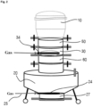
- Fig. 2 is a schematic diagram for describing constitution of the gas inlet part 30 and the product collecting part 20 in more detail.
- the gas inlet part 30 is equipped with a nozzle 34 for spraying the introduced gas upward toward the drying part 10 thereby feeding the gas through the opening part of the first valve 50, preferably.
- the shape of the nozzle 34 may refer to Fig. 3 .
- the first valve 50 is installed at to bottom of the drying part 10, whereunder the gas inlet part 30 and the second valve 60 are installed.
- the product collecting part 20 may be located below the second valve 60, and for easier product collecting, the second gas inlet 25 and the third valve 27 may be installed at the bottom of the product collecting part 20.
- the gas introduced through the second gas inlet 25 is sprayed through the spray nozzle 24 to prevent agglomeration of the product during the product discharging process.
- the shape of the spray nozzle 24 may be the same as illustrated in Fig. 3 , but not limited thereto.
- the gas to be introduced may preferably be inert gas and there is no need to preheat the gas.
- Fig. 4 to Fig. 5 illustrate an example of the first valve 50.
- the valve may be a butterfly valve or a damper valve.
- the first valve has a central axis 51. Accordingly, the valve is rotatable and foldable on the axis and therefore, the valve is openable.
- the butterfly valve or the damper valve In order to prevent the product flowing out during product drying, the butterfly valve or the damper valve is used. However, the valve blocks the gas flow when the valve is closed, and therefore hot air flow of the upper part of the valve (drying part) is reduced. Thus, it causes reduction of the drying efficiency.
- the opening part 53 of the first valve 50 may improve the drying efficiency by allowing hot air flow through introduction of the gas from the gas inlet part 30 to the drying part 10, while preventing the product from discharging to the collecting part 20 during the product drying process in the drying part 10.
- the first valve may have a plurality of opening parts 53 on the surface of a wing part 52 of the butterfly valve or the damper valve.
- a mesh sheet through which the carbon nanotube product can't be communicated but only flow can be communicated may be put over a part or a whole of the opening part 53.
- a bubble cap 55 may be covered over a part or a whole of the opening part 53.
- the present invention by placing the first valve 50 and the second valve 60 at the bottom of the drying part 10, it is possible to feed hot air into the drying part by using the high temperature gas while first valve 50 is closed. Thus, the drying process can be proceeded efficiently. Further, during the collecting process of the dried product, it is possible to open the first valve 50 to introduce the product into the gas inlet 30, and then to close the first valve 50 and to open the second valve 60 to introduce the product into the collecting part 20. Thus, without stopping the drying process or lowering the temperature, it is possible to proceed the drying process and the product collecting process continuously.
- Fig. 1 The device illustrated in Fig. 1 was assembled by using a lab-scale cylinder-type high temperature dryer (Internal diameter 50mm quartz tube), and Fig. 6 and Fig. 7 show the results of tests performed with the device. Test conditions are as listed in the following Table 1. [Table 1] Test 1 Test 2 Input of CNT pellet 300 g 300 g Drying time 90 min 180 min Nitrogen gas flow rate 2.7 cm/s 2.7 cm/s Furnace temperature 300 °C 300 °C
- the tests were performed at the same conditions except for changing the drying time, and the drying rate, the percentage of water content and the bed temperature change were observed.
- Fig. 6 shows the drying rate and the bed temperature according to the drying time
- Fig. 7 shows the percentage of water content according to the drying time.
Landscapes
- Chemical & Material Sciences (AREA)
- Engineering & Computer Science (AREA)
- Organic Chemistry (AREA)
- Chemical Kinetics & Catalysis (AREA)
- Nanotechnology (AREA)
- Environmental & Geological Engineering (AREA)
- Materials Engineering (AREA)
- Thermal Sciences (AREA)
- Physics & Mathematics (AREA)
- Mechanical Engineering (AREA)
- General Engineering & Computer Science (AREA)
- Inorganic Chemistry (AREA)
- Health & Medical Sciences (AREA)
- Medicinal Chemistry (AREA)
- Polymers & Plastics (AREA)
- Carbon And Carbon Compounds (AREA)
Claims (14)
- Vorrichtung (100) zum Trocknen und Sammeln eines Kohlenstoffnanoröhrenprodukts, aufweisend:ein Trocknungsteil (10), das ein zu trocknendes Kohlenstoffnanoröhrenprodukt aufnimmt und das Produkt trocknet;ein Produktsammelteil (20), das an der Unterseite des Trocknungsteils (10) installiert ist;ein Gaseinlassteil (30), das zwischen dem Trocknungsteil (10) und dem Produktsammelteil (20) installiert ist, zum Einströmen von Gas in das Trocknungsteil (10); undein öffenbares Ventil (50), das zwischen dem Trocknungsteil (10) und dem Produktsammelteil (20) installiert ist, zum Einführen des Produkts in das Gaseinlassteil (30), wenn das Ventil (50) geöffnet wird, und wobei das Ventil (50) mehrere Öffnungsteile (53) aufweist, die eine Fluidverbindung ermöglichen, wobei die Öffnungsteile (53) des Ventils (50) einen Heißluftgasstrom von dem Gaseinlassteil (30) in das Trocknungsteil (10) ermöglichen, während sie verhindern, dass das Produkt während des Produkttrocknungsprozesses in dem Trocknungsteil (10) zu dem Sammelteil (20) abgegeben wird, während das Ventil (50) geschlossen ist.
- Vorrichtung zum Trocknen und Sammeln eines Kohlenstoffnanoröhrenprodukts nach Anspruch 1,
wobei das Gaseinlassteil (30) zwischen dem Trocknungsteil (10) und dem Produktsammelteil (20) installiert ist und das Ventil (50) aufweist:- ein erstes Ventil (50), das zwischen dem Trocknungsteil (10) und dem Gaseinlassteil (30) installiert ist, und- ein zweites Ventil (60), das zwischen dem Gaseinlassteil (30) und dem Produktsammelteil (20) installiert ist,wobei das erste Ventil (50) an der Unterseite des Trocknungsteils (10) installiert ist, unter der das Gaseinlassteil (30) und das zweite Ventil (60) installiert sind. - Vorrichtung zum Trocknen und Sammeln eines Kohlenstoffnanoröhrenprodukts nach Anspruch 2,
wobei das erste Ventil (50) oder das zweite Ventil (60) voneinander unabhängig ein Drosselventil oder ein Dämpferventil ist. - Vorrichtung zum Trocknen und Sammeln eines Kohlenstoffnanoröhrenprodukts nach Anspruch 3,
wobei das erste Ventil (50) mehrere Öffnungsteile (53) auf der Oberfläche eines Flügelteils (52) des Drosselventils oder des Dämpferventils aufweist. - Vorrichtung zum Trocknen und Sammeln eines Kohlenstoffnanoröhrenprodukts nach Anspruch 4,
wobei eine Netzlage, durch die nicht das Kohlenstoffnanoröhrenprodukt, sondern nur ein Fluid passieren kann, über einen Teil oder über die Gesamtheit des Öffnungsteils (53) gelegt ist. - Vorrichtung zum Trocknen und Sammeln eines Kohlenstoffnanoröhrenprodukts nach Anspruch 4,
wobei eine Blasenkappe (55) einen Teil oder die Gesamtheit des Öffnungsteils (53) abdeckt. - Vorrichtung zum Trocknen und Sammeln eines Kohlenstoffnanoröhrenprodukts nach Anspruch 1,
wobei ein Gasauslass (13) auf einer Oberseite des Trocknungsteils (10) installiert ist, um den Druck in dem Trocknungsteil (10) zu steuern. - Vorrichtung zum Trocknen und Sammeln eines Kohlenstoffnanoröhrenprodukts nach Anspruch 1,
wobei ein drittes Ventil (27) an der Unterseite des Produktsammelteils (20) installiert ist, um ein Produkt abzugeben, wobei das zweite Ventil (60) oder das dritte Ventil (27) ein Drosselventil oder ein Dämpferventil ohne ein Öffnungsteil ist. - Vorrichtung zum Trocknen und Sammeln eines Kohlenstoffnanoröhrenprodukts nach Anspruch 8,
wobei ein zweites Gaseinlassteil (25) an dem Produktsammelteil (20) installiert ist, um Gas einzuführen, das das Abgeben eines Produkts unterstützt. - Verfahren zum Herstellen eines Kohlenstoffnanoröhrenprodukts, umfassend die Schritte:Aufnehmen eines zu trocknenden Kohlenstoffnanoröhrenprodukts in einem Trocknungsteil (10);Trocknen des Kohlenstoffnanoröhrenprodukts, während durch ein Gaseinlassteil (30), das zwischen dem Trocknungsteil (10) und einem Produktsammelteil (20) an der Unterseite des Trocknungsteils (10) installiert ist, Gas in das Trocknungsteil (10) einströmt;Steuern des Drucks in dem Trocknungsteil (10) durch Abgeben von Gas durch einen Gasauslass (13), der auf einer Oberseite des Trocknungsteils (10) installiert ist; undSammeln des getrockneten Kohlenstoffnanoröhrenprodukts durch das Produktsammelteil (20), das an der Unterseite des Trocknungsteils (10) installiert ist,wobei ein Ventil (50), das mehrere Öffnungsteile (53) aufweist, die eine Fluidverbindung ermöglichen, zwischen dem Trocknungsteil (10) und dem Produktsammelteil (20) installiert ist, so dass ein Gasstrom ermöglicht wird, während eine Abgabe des Produkts während des Produkttrocknungsprozesses in dem Trocknungsteil (10) verhindert wird, während das Ventil (50) geschlossen ist.
- Verfahren zum Herstellen eines Kohlenstoffnanoröhrenprodukts nach Anspruch 10,wobei das Gaseinlassteil (30) zwischen dem Trocknungsteil (10) und dem Produktsammelteil (20) installiert ist unddas Ventil (50), das mehrere Öffnungsteile (53) aufweist, ein erstes Ventil (50), das zwischen dem Trocknungsteil (10) und dem Gaseinlassteil (30) installiert ist, und ein zweites Ventil (60), das zwischen dem Gaseinlassteil (30) und dem Produktsammelteil (20) installiert ist, aufweist,wobei, wenn ein Trocknungsprozess durchgeführt wird, das Gas einströmt, wobei das erste Ventil (50) geschlossen ist, um den Trocknungsprozess durchzuführen, undwenn das getrocknete Produkt gesammelt wird, das erste Ventil (50) geöffnet wird, um das Produkt in das Gaseinlassteil (30) einzuführen, und dann das erste Ventil (50) geschlossen wird und das zweite Ventil (60) geöffnet wird, um das Produkt in das Sammelteil (20) einzuführen.
- Verfahren zum Herstellen eines Kohlenstoffnanoröhrenprodukts nach Anspruch 10, das ferner die Schritte aufweist:Pyrolysieren einer organischen Verbindung mit einem Übergangsmetall oder seiner Verbindung als Katalysator in einem Pyrolyseofen, um Kohlenstoffnanoröhren zu erhalten, die in das Trocknungsteil (10) einzuführen sind;Trennen von reaktivem Abgas, das bei dem Pyrolyseprozess erzeugt wird, von den Kohlenstoffnanoröhren; undVerbrennen des reaktiven Abgases, das von den Kohlenstoffnanoröhren getrennt wird.
- Verfahren zum Herstellen eines Kohlenstoffnanoröhrenprodukts nach Anspruch 10, wobei das Abgas, das von dem Gasauslass (13) abgegeben wird, verbrannt wird.
- Verfahren zum Herstellen eines Kohlenstoffnanoröhrenprodukts nach Anspruch 13,
wobei das reaktive Abgas, das bei einem Pyrolyseprozess zum Herstellen eines Kohlenstoffnanoröhrenprodukts erzeugt wird, auch verbrannt wird, wenn das Abgas verbrannt wird.
Applications Claiming Priority (2)
| Application Number | Priority Date | Filing Date | Title |
|---|---|---|---|
| KR1020160089098A KR102047370B1 (ko) | 2016-07-14 | 2016-07-14 | 카본나노튜브 제품 건조 및 회수 장치 및 이를 이용한 카본나노튜브 제조방법 |
| PCT/KR2017/007459 WO2018012876A1 (ko) | 2016-07-14 | 2017-07-12 | 카본나노튜브 제품 건조 및 회수 장치와 이를 이용한 카본나노튜브 제조방법 |
Publications (3)
| Publication Number | Publication Date |
|---|---|
| EP3339247A1 EP3339247A1 (de) | 2018-06-27 |
| EP3339247A4 EP3339247A4 (de) | 2018-11-21 |
| EP3339247B1 true EP3339247B1 (de) | 2024-12-18 |
Family
ID=60952631
Family Applications (1)
| Application Number | Title | Priority Date | Filing Date |
|---|---|---|---|
| EP17827946.9A Active EP3339247B1 (de) | 2016-07-14 | 2017-07-12 | Vorrichtung zur trocknung und rückgewinnung eines kohlenstoffnanoröhrenprodukts und verfahren zur herstellung von kohlenstoffnanoröhren damit |
Country Status (5)
| Country | Link |
|---|---|
| US (1) | US10758882B2 (de) |
| EP (1) | EP3339247B1 (de) |
| KR (1) | KR102047370B1 (de) |
| CN (1) | CN108349739B (de) |
| WO (1) | WO2018012876A1 (de) |
Families Citing this family (5)
| Publication number | Priority date | Publication date | Assignee | Title |
|---|---|---|---|---|
| US11186488B2 (en) * | 2018-03-30 | 2021-11-30 | Zeon Corporation | Separation and recovery method |
| CN108580924B (zh) * | 2018-06-08 | 2020-05-05 | 厦门大学 | 一种纳米材料液相连续合成方法 |
| CN112107948B (zh) * | 2020-10-13 | 2021-07-23 | 中国城市建设研究院有限公司 | 生活垃圾焚烧烟气的湿法处理设备 |
| KR102857029B1 (ko) * | 2021-12-24 | 2025-09-08 | 엘티메탈 주식회사 | 연료전지 백금 촉매의 후처리 공정 처리장치 |
| CN114850017A (zh) * | 2022-03-23 | 2022-08-05 | 镇江新纳材料科技有限公司 | 一种基于碳纳米管粉体压缩工艺的造粒设备及其造粒方法 |
Citations (1)
| Publication number | Priority date | Publication date | Assignee | Title |
|---|---|---|---|---|
| US20040124093A1 (en) * | 2002-10-16 | 2004-07-01 | Dal-Young Jung | Continuous production and separation of carbon-based materials |
Family Cites Families (19)
| Publication number | Priority date | Publication date | Assignee | Title |
|---|---|---|---|---|
| JPS5229467A (en) * | 1975-09-01 | 1977-03-05 | Unitika Ltd | Method of removing nox |
| US8062410B2 (en) * | 2004-10-12 | 2011-11-22 | Great River Energy | Apparatus and method of enhancing the quality of high-moisture materials and separating and concentrating organic and/or non-organic material contained therein |
| CN100434359C (zh) * | 2005-01-05 | 2008-11-19 | 中国科学院大连化学物理研究所 | 一种连续生产纳米碳材料的方法及装置 |
| JP5266907B2 (ja) | 2007-06-29 | 2013-08-21 | 東レ株式会社 | カーボンナノチューブ集合体、分散体および導電性フィルム |
| US20090181846A1 (en) * | 2007-12-24 | 2009-07-16 | Joung Hyeon Lim | Process for preparing catalyst for synthesis of carbon nanotubes using spray pyrolysis |
| JP5408619B2 (ja) * | 2008-01-24 | 2014-02-05 | 独立行政法人産業技術総合研究所 | 有機ナノチューブ製造方法および製造装置 |
| JP5117251B2 (ja) * | 2008-03-31 | 2013-01-16 | 株式会社東芝 | ナノカーボン・炭化物連続製造装置 |
| KR101012770B1 (ko) * | 2008-05-16 | 2011-02-08 | 한국표준과학연구원 | 가변압력을 이용한 건조기 및 이를 이용한 건조방법 |
| WO2011102433A1 (ja) * | 2010-02-19 | 2011-08-25 | 国立大学法人東京大学 | ナノカーボン材料製造装置及びナノカーボン材料の製造方法 |
| FR2972942B1 (fr) * | 2011-03-21 | 2017-11-24 | Arkema France | Procede de fabrication de nanotubes de carbone et appareil pour la mise en oeuvre du procede. |
| CN102502591B (zh) * | 2011-11-28 | 2013-09-04 | 深圳市贝特瑞纳米科技有限公司 | 纳米碳纤维的制备方法和设备 |
| CN102602912B (zh) * | 2012-03-15 | 2013-12-04 | 南昌大学 | 连续生产晶须状碳纳米管的合成装置 |
| TWI627130B (zh) * | 2012-04-18 | 2018-06-21 | 美商艾克頌美孚上游研究公司 | 由連續反應器流出物移出碳奈米管之方法 |
| KR20150129090A (ko) * | 2012-09-04 | 2015-11-19 | 삼성전기주식회사 | 건조 시스템 |
| KR101408950B1 (ko) | 2012-10-18 | 2014-06-17 | 주식회사 효성 | 압축 cnt의 제조방법 및 그에 의한 압축 cnt |
| CN103344093A (zh) * | 2013-06-09 | 2013-10-09 | 山东奥诺能源科技有限公司 | 一种立式连续流化床造粒干燥装置及方法 |
| KR101781252B1 (ko) * | 2014-09-26 | 2017-09-22 | 주식회사 엘지화학 | 카본나노튜브 응집체의 제조방법 |
| CN105439119B (zh) * | 2015-12-02 | 2017-08-25 | 苏州捷迪纳米科技有限公司 | 立式连续碳纳米管纤维的制备装置以及制备方法 |
| CN105399095B (zh) * | 2015-12-28 | 2018-05-08 | 大连理工大学 | 一种用于碱活化法制备高比表面积活性炭的装置及方法 |
-
2016
- 2016-07-14 KR KR1020160089098A patent/KR102047370B1/ko active Active
-
2017
- 2017-07-12 US US15/769,194 patent/US10758882B2/en active Active
- 2017-07-12 WO PCT/KR2017/007459 patent/WO2018012876A1/ko not_active Ceased
- 2017-07-12 EP EP17827946.9A patent/EP3339247B1/de active Active
- 2017-07-12 CN CN201780003880.XA patent/CN108349739B/zh active Active
Patent Citations (1)
| Publication number | Priority date | Publication date | Assignee | Title |
|---|---|---|---|---|
| US20040124093A1 (en) * | 2002-10-16 | 2004-07-01 | Dal-Young Jung | Continuous production and separation of carbon-based materials |
Also Published As
| Publication number | Publication date |
|---|---|
| EP3339247A4 (de) | 2018-11-21 |
| US20180304218A1 (en) | 2018-10-25 |
| CN108349739A (zh) | 2018-07-31 |
| KR20180007782A (ko) | 2018-01-24 |
| KR102047370B1 (ko) | 2019-11-22 |
| WO2018012876A1 (ko) | 2018-01-18 |
| CN108349739B (zh) | 2021-10-01 |
| US10758882B2 (en) | 2020-09-01 |
| EP3339247A1 (de) | 2018-06-27 |
Similar Documents
| Publication | Publication Date | Title |
|---|---|---|
| EP3339247B1 (de) | Vorrichtung zur trocknung und rückgewinnung eines kohlenstoffnanoröhrenprodukts und verfahren zur herstellung von kohlenstoffnanoröhren damit | |
| JP5898618B2 (ja) | カーボンナノチューブ凝集体 | |
| JP5220833B2 (ja) | 担持触媒を用いた単一層カーボンナノチューブの製造方法 | |
| CN103534203B (zh) | 用于制造纳米碳的方法和制造装置 | |
| CN109836851B (zh) | 碳黑的氧化方法及包括其的碳黑的制备方法 | |
| EP3613703A1 (de) | Vorrichtung und verfahren zur einstufigen kontinuierlichen herstellung von kohlenstoffnanoröhrchen | |
| JP4410010B2 (ja) | ナノカーボン材料の製造方法 | |
| Mittal | Encapsulation nanotechnologies | |
| US11171324B2 (en) | System and method of producing a composite product | |
| Salice et al. | Efficient functionalization of carbon nanotubes | |
| CN107001050A (zh) | 用于碳化作为粉末的木质纤维素材料的新方法 | |
| KR20140124457A (ko) | 유동층 반응기 및 이를 이용한 카본나노구조물 제조방법 | |
| JP6403144B2 (ja) | 気相法微細炭素繊維の製造方法 | |
| TW201412644A (zh) | 碳化鈦微粒子之製造方法 | |
| Lee et al. | Colloid syringeless electrospinning toward nonwoven nanofiber web containing a massive amount of inorganic fillers | |
| See et al. | CaCo3 supported Co‐Fe catalysts for carbon nanotube synthesis in fluidized bed reactors | |
| CN105731423B (zh) | 一种煤热解生成碳纳米管的一体化装置和方法 | |
| KR100808027B1 (ko) | 기상반응법을 이용한 니켈 나노분말의 제조방법 | |
| RU2516548C2 (ru) | Способ получения углерод-металлического материала каталитическим пиролизом этанола | |
| CN210736632U (zh) | 一种废轮胎裂解炭黑的改性装置 | |
| CN117563625A (zh) | 一种钴系碳纳米管催化剂其制备方法及应用 | |
| KR101016031B1 (ko) | 탄소나노튜브 합성 장치 | |
| CN223945624U (zh) | 一种连续制备手性富集单壁碳纳米管的流化床 | |
| KR100526728B1 (ko) | 염화텅스텐으로부터 나노 텅스텐 분말의 제조 방법 | |
| KR20150120615A (ko) | 촉매 공급 장치, 이를 구비한 유동층 반응기 및 이를 이용한 탄소 나노구조물의 제조방법 |
Legal Events
| Date | Code | Title | Description |
|---|---|---|---|
| STAA | Information on the status of an ep patent application or granted ep patent |
Free format text: STATUS: THE INTERNATIONAL PUBLICATION HAS BEEN MADE |
|
| PUAI | Public reference made under article 153(3) epc to a published international application that has entered the european phase |
Free format text: ORIGINAL CODE: 0009012 |
|
| STAA | Information on the status of an ep patent application or granted ep patent |
Free format text: STATUS: REQUEST FOR EXAMINATION WAS MADE |
|
| 17P | Request for examination filed |
Effective date: 20180320 |
|
| AK | Designated contracting states |
Kind code of ref document: A1 Designated state(s): AL AT BE BG CH CY CZ DE DK EE ES FI FR GB GR HR HU IE IS IT LI LT LU LV MC MK MT NL NO PL PT RO RS SE SI SK SM TR |
|
| AX | Request for extension of the european patent |
Extension state: BA ME |
|
| A4 | Supplementary search report drawn up and despatched |
Effective date: 20181023 |
|
| RIC1 | Information provided on ipc code assigned before grant |
Ipc: B01J 2/04 20060101ALI20181017BHEP Ipc: F23G 7/06 20060101ALI20181017BHEP Ipc: B01J 6/00 20060101ALI20181017BHEP Ipc: C01B 32/16 20170101AFI20181017BHEP Ipc: B01J 2/16 20060101ALI20181017BHEP |
|
| DAV | Request for validation of the european patent (deleted) | ||
| DAX | Request for extension of the european patent (deleted) | ||
| STAA | Information on the status of an ep patent application or granted ep patent |
Free format text: STATUS: EXAMINATION IS IN PROGRESS |
|
| 17Q | First examination report despatched |
Effective date: 20201124 |
|
| GRAP | Despatch of communication of intention to grant a patent |
Free format text: ORIGINAL CODE: EPIDOSNIGR1 |
|
| STAA | Information on the status of an ep patent application or granted ep patent |
Free format text: STATUS: GRANT OF PATENT IS INTENDED |
|
| GRAS | Grant fee paid |
Free format text: ORIGINAL CODE: EPIDOSNIGR3 |
|
| INTG | Intention to grant announced |
Effective date: 20241010 |
|
| GRAA | (expected) grant |
Free format text: ORIGINAL CODE: 0009210 |
|
| STAA | Information on the status of an ep patent application or granted ep patent |
Free format text: STATUS: THE PATENT HAS BEEN GRANTED |
|
| AK | Designated contracting states |
Kind code of ref document: B1 Designated state(s): AL AT BE BG CH CY CZ DE DK EE ES FI FR GB GR HR HU IE IS IT LI LT LU LV MC MK MT NL NO PL PT RO RS SE SI SK SM TR |
|
| REG | Reference to a national code |
Ref country code: GB Ref legal event code: FG4D |
|
| REG | Reference to a national code |
Ref country code: CH Ref legal event code: EP |
|
| REG | Reference to a national code |
Ref country code: DE Ref legal event code: R096 Ref document number: 602017086853 Country of ref document: DE |
|
| REG | Reference to a national code |
Ref country code: IE Ref legal event code: FG4D |
|
| REG | Reference to a national code |
Ref country code: LT Ref legal event code: MG9D |
|
| PG25 | Lapsed in a contracting state [announced via postgrant information from national office to epo] |
Ref country code: HR Free format text: LAPSE BECAUSE OF FAILURE TO SUBMIT A TRANSLATION OF THE DESCRIPTION OR TO PAY THE FEE WITHIN THE PRESCRIBED TIME-LIMIT Effective date: 20241218 |
|
| PG25 | Lapsed in a contracting state [announced via postgrant information from national office to epo] |
Ref country code: FI Free format text: LAPSE BECAUSE OF FAILURE TO SUBMIT A TRANSLATION OF THE DESCRIPTION OR TO PAY THE FEE WITHIN THE PRESCRIBED TIME-LIMIT Effective date: 20241218 |
|
| PG25 | Lapsed in a contracting state [announced via postgrant information from national office to epo] |
Ref country code: BG Free format text: LAPSE BECAUSE OF FAILURE TO SUBMIT A TRANSLATION OF THE DESCRIPTION OR TO PAY THE FEE WITHIN THE PRESCRIBED TIME-LIMIT Effective date: 20241218 |
|
| PG25 | Lapsed in a contracting state [announced via postgrant information from national office to epo] |
Ref country code: NO Free format text: LAPSE BECAUSE OF FAILURE TO SUBMIT A TRANSLATION OF THE DESCRIPTION OR TO PAY THE FEE WITHIN THE PRESCRIBED TIME-LIMIT Effective date: 20250318 |
|
| REG | Reference to a national code |
Ref country code: NL Ref legal event code: MP Effective date: 20241218 |
|
| PG25 | Lapsed in a contracting state [announced via postgrant information from national office to epo] |
Ref country code: GR Free format text: LAPSE BECAUSE OF FAILURE TO SUBMIT A TRANSLATION OF THE DESCRIPTION OR TO PAY THE FEE WITHIN THE PRESCRIBED TIME-LIMIT Effective date: 20250319 Ref country code: LV Free format text: LAPSE BECAUSE OF FAILURE TO SUBMIT A TRANSLATION OF THE DESCRIPTION OR TO PAY THE FEE WITHIN THE PRESCRIBED TIME-LIMIT Effective date: 20241218 |
|
| PG25 | Lapsed in a contracting state [announced via postgrant information from national office to epo] |
Ref country code: RS Free format text: LAPSE BECAUSE OF FAILURE TO SUBMIT A TRANSLATION OF THE DESCRIPTION OR TO PAY THE FEE WITHIN THE PRESCRIBED TIME-LIMIT Effective date: 20250318 |
|
| PG25 | Lapsed in a contracting state [announced via postgrant information from national office to epo] |
Ref country code: NL Free format text: LAPSE BECAUSE OF FAILURE TO SUBMIT A TRANSLATION OF THE DESCRIPTION OR TO PAY THE FEE WITHIN THE PRESCRIBED TIME-LIMIT Effective date: 20241218 |
|
| REG | Reference to a national code |
Ref country code: AT Ref legal event code: MK05 Ref document number: 1752142 Country of ref document: AT Kind code of ref document: T Effective date: 20241218 |
|
| PG25 | Lapsed in a contracting state [announced via postgrant information from national office to epo] |
Ref country code: SM Free format text: LAPSE BECAUSE OF FAILURE TO SUBMIT A TRANSLATION OF THE DESCRIPTION OR TO PAY THE FEE WITHIN THE PRESCRIBED TIME-LIMIT Effective date: 20241218 |
|
| PG25 | Lapsed in a contracting state [announced via postgrant information from national office to epo] |
Ref country code: PL Free format text: LAPSE BECAUSE OF FAILURE TO SUBMIT A TRANSLATION OF THE DESCRIPTION OR TO PAY THE FEE WITHIN THE PRESCRIBED TIME-LIMIT Effective date: 20241218 |
|
| PG25 | Lapsed in a contracting state [announced via postgrant information from national office to epo] |
Ref country code: ES Free format text: LAPSE BECAUSE OF FAILURE TO SUBMIT A TRANSLATION OF THE DESCRIPTION OR TO PAY THE FEE WITHIN THE PRESCRIBED TIME-LIMIT Effective date: 20241218 |
|
| PGFP | Annual fee paid to national office [announced via postgrant information from national office to epo] |
Ref country code: GB Payment date: 20250624 Year of fee payment: 9 |
|
| PG25 | Lapsed in a contracting state [announced via postgrant information from national office to epo] |
Ref country code: IS Free format text: LAPSE BECAUSE OF FAILURE TO SUBMIT A TRANSLATION OF THE DESCRIPTION OR TO PAY THE FEE WITHIN THE PRESCRIBED TIME-LIMIT Effective date: 20250418 |
|
| PG25 | Lapsed in a contracting state [announced via postgrant information from national office to epo] |
Ref country code: PT Free format text: LAPSE BECAUSE OF FAILURE TO SUBMIT A TRANSLATION OF THE DESCRIPTION OR TO PAY THE FEE WITHIN THE PRESCRIBED TIME-LIMIT Effective date: 20250421 |
|
| PG25 | Lapsed in a contracting state [announced via postgrant information from national office to epo] |
Ref country code: EE Free format text: LAPSE BECAUSE OF FAILURE TO SUBMIT A TRANSLATION OF THE DESCRIPTION OR TO PAY THE FEE WITHIN THE PRESCRIBED TIME-LIMIT Effective date: 20241218 |
|
| PGFP | Annual fee paid to national office [announced via postgrant information from national office to epo] |
Ref country code: FR Payment date: 20250624 Year of fee payment: 9 |
|
| PG25 | Lapsed in a contracting state [announced via postgrant information from national office to epo] |
Ref country code: RO Free format text: LAPSE BECAUSE OF FAILURE TO SUBMIT A TRANSLATION OF THE DESCRIPTION OR TO PAY THE FEE WITHIN THE PRESCRIBED TIME-LIMIT Effective date: 20241218 Ref country code: AT Free format text: LAPSE BECAUSE OF FAILURE TO SUBMIT A TRANSLATION OF THE DESCRIPTION OR TO PAY THE FEE WITHIN THE PRESCRIBED TIME-LIMIT Effective date: 20241218 |
|
| PG25 | Lapsed in a contracting state [announced via postgrant information from national office to epo] |
Ref country code: SK Free format text: LAPSE BECAUSE OF FAILURE TO SUBMIT A TRANSLATION OF THE DESCRIPTION OR TO PAY THE FEE WITHIN THE PRESCRIBED TIME-LIMIT Effective date: 20241218 |
|
| PG25 | Lapsed in a contracting state [announced via postgrant information from national office to epo] |
Ref country code: CZ Free format text: LAPSE BECAUSE OF FAILURE TO SUBMIT A TRANSLATION OF THE DESCRIPTION OR TO PAY THE FEE WITHIN THE PRESCRIBED TIME-LIMIT Effective date: 20241218 |
|
| PG25 | Lapsed in a contracting state [announced via postgrant information from national office to epo] |
Ref country code: IT Free format text: LAPSE BECAUSE OF FAILURE TO SUBMIT A TRANSLATION OF THE DESCRIPTION OR TO PAY THE FEE WITHIN THE PRESCRIBED TIME-LIMIT Effective date: 20241218 |
|
| PG25 | Lapsed in a contracting state [announced via postgrant information from national office to epo] |
Ref country code: SE Free format text: LAPSE BECAUSE OF FAILURE TO SUBMIT A TRANSLATION OF THE DESCRIPTION OR TO PAY THE FEE WITHIN THE PRESCRIBED TIME-LIMIT Effective date: 20241218 |
|
| REG | Reference to a national code |
Ref country code: DE Ref legal event code: R097 Ref document number: 602017086853 Country of ref document: DE |
|
| PG25 | Lapsed in a contracting state [announced via postgrant information from national office to epo] |
Ref country code: DK Free format text: LAPSE BECAUSE OF FAILURE TO SUBMIT A TRANSLATION OF THE DESCRIPTION OR TO PAY THE FEE WITHIN THE PRESCRIBED TIME-LIMIT Effective date: 20241218 |
|
| PGFP | Annual fee paid to national office [announced via postgrant information from national office to epo] |
Ref country code: DE Payment date: 20250624 Year of fee payment: 9 |
|
| PLBE | No opposition filed within time limit |
Free format text: ORIGINAL CODE: 0009261 |
|
| STAA | Information on the status of an ep patent application or granted ep patent |
Free format text: STATUS: NO OPPOSITION FILED WITHIN TIME LIMIT |
|
| REG | Reference to a national code |
Ref country code: CH Ref legal event code: L10 Free format text: ST27 STATUS EVENT CODE: U-0-0-L10-L00 (AS PROVIDED BY THE NATIONAL OFFICE) Effective date: 20251029 |
|
| 26N | No opposition filed |
Effective date: 20250919 |
|
| REG | Reference to a national code |
Ref country code: CH Ref legal event code: H13 Free format text: ST27 STATUS EVENT CODE: U-0-0-H10-H13 (AS PROVIDED BY THE NATIONAL OFFICE) Effective date: 20260224 |
|
| PG25 | Lapsed in a contracting state [announced via postgrant information from national office to epo] |
Ref country code: LU Free format text: LAPSE BECAUSE OF NON-PAYMENT OF DUE FEES Effective date: 20250712 |
|
| REG | Reference to a national code |
Ref country code: BE Ref legal event code: MM Effective date: 20250731 |
|
| PG25 | Lapsed in a contracting state [announced via postgrant information from national office to epo] |
Ref country code: BE Free format text: LAPSE BECAUSE OF NON-PAYMENT OF DUE FEES Effective date: 20250731 |