EP3334268B1 - Streuer - Google Patents
Streuer Download PDFInfo
- Publication number
- EP3334268B1 EP3334268B1 EP16751583.2A EP16751583A EP3334268B1 EP 3334268 B1 EP3334268 B1 EP 3334268B1 EP 16751583 A EP16751583 A EP 16751583A EP 3334268 B1 EP3334268 B1 EP 3334268B1
- Authority
- EP
- European Patent Office
- Prior art keywords
- see
- frame
- container
- distributor
- base frame
- Prior art date
- Legal status (The legal status is an assumption and is not a legal conclusion. Google has not performed a legal analysis and makes no representation as to the accuracy of the status listed.)
- Active
Links
- 230000007480 spreading Effects 0.000 claims description 17
- 230000001413 cellular effect Effects 0.000 claims 1
- 239000000463 material Substances 0.000 description 5
- 230000008901 benefit Effects 0.000 description 3
- 230000001419 dependent effect Effects 0.000 description 2
- 230000000694 effects Effects 0.000 description 2
- 238000000034 method Methods 0.000 description 2
- 230000008569 process Effects 0.000 description 2
- 239000002689 soil Substances 0.000 description 2
- 238000009331 sowing Methods 0.000 description 2
- 206010012335 Dependence Diseases 0.000 description 1
- 244000007853 Sarothamnus scoparius Species 0.000 description 1
- 230000008859 change Effects 0.000 description 1
- 238000006243 chemical reaction Methods 0.000 description 1
- 230000005484 gravity Effects 0.000 description 1
- 230000009467 reduction Effects 0.000 description 1
- 238000003971 tillage Methods 0.000 description 1
Images


Classifications
-
- A—HUMAN NECESSITIES
- A01—AGRICULTURE; FORESTRY; ANIMAL HUSBANDRY; HUNTING; TRAPPING; FISHING
- A01C—PLANTING; SOWING; FERTILISING
- A01C7/00—Sowing
- A01C7/20—Parts of seeders for conducting and depositing seed
- A01C7/201—Mounting of the seeding tools
-
- A—HUMAN NECESSITIES
- A01—AGRICULTURE; FORESTRY; ANIMAL HUSBANDRY; HUNTING; TRAPPING; FISHING
- A01C—PLANTING; SOWING; FERTILISING
- A01C17/00—Fertilisers or seeders with centrifugal wheels
- A01C17/001—Centrifugal throwing devices with a vertical axis
-
- A—HUMAN NECESSITIES
- A01—AGRICULTURE; FORESTRY; ANIMAL HUSBANDRY; HUNTING; TRAPPING; FISHING
- A01C—PLANTING; SOWING; FERTILISING
- A01C15/00—Fertiliser distributors
- A01C15/005—Undercarriages, tanks, hoppers, stirrers specially adapted for seeders or fertiliser distributors
-
- A—HUMAN NECESSITIES
- A01—AGRICULTURE; FORESTRY; ANIMAL HUSBANDRY; HUNTING; TRAPPING; FISHING
- A01C—PLANTING; SOWING; FERTILISING
- A01C17/00—Fertilisers or seeders with centrifugal wheels
- A01C17/006—Regulating or dosing devices
-
- A—HUMAN NECESSITIES
- A01—AGRICULTURE; FORESTRY; ANIMAL HUSBANDRY; HUNTING; TRAPPING; FISHING
- A01C—PLANTING; SOWING; FERTILISING
- A01C17/00—Fertilisers or seeders with centrifugal wheels
- A01C17/006—Regulating or dosing devices
- A01C17/008—Devices controlling the quantity or the distribution pattern
-
- A—HUMAN NECESSITIES
- A01—AGRICULTURE; FORESTRY; ANIMAL HUSBANDRY; HUNTING; TRAPPING; FISHING
- A01C—PLANTING; SOWING; FERTILISING
- A01C7/00—Sowing
- A01C7/08—Broadcast seeders; Seeders depositing seeds in rows
- A01C7/085—Broadcast seeders
-
- A—HUMAN NECESSITIES
- A01—AGRICULTURE; FORESTRY; ANIMAL HUSBANDRY; HUNTING; TRAPPING; FISHING
- A01C—PLANTING; SOWING; FERTILISING
- A01C7/00—Sowing
- A01C7/08—Broadcast seeders; Seeders depositing seeds in rows
- A01C7/10—Devices for adjusting the seed-box ; Regulation of machines for depositing quantities at intervals
- A01C7/107—Calibration of the seed rate
-
- A—HUMAN NECESSITIES
- A01—AGRICULTURE; FORESTRY; ANIMAL HUSBANDRY; HUNTING; TRAPPING; FISHING
- A01C—PLANTING; SOWING; FERTILISING
- A01C7/00—Sowing
- A01C7/20—Parts of seeders for conducting and depositing seed
- A01C7/208—Chassis; Coupling means to a tractor or the like; Lifting means; Side markers
-
- F—MECHANICAL ENGINEERING; LIGHTING; HEATING; WEAPONS; BLASTING
- F02—COMBUSTION ENGINES; HOT-GAS OR COMBUSTION-PRODUCT ENGINE PLANTS
- F02B—INTERNAL-COMBUSTION PISTON ENGINES; COMBUSTION ENGINES IN GENERAL
- F02B19/00—Engines characterised by precombustion chambers
- F02B19/10—Engines characterised by precombustion chambers with fuel introduced partly into pre-combustion chamber, and partly into cylinder
- F02B19/1019—Engines characterised by precombustion chambers with fuel introduced partly into pre-combustion chamber, and partly into cylinder with only one pre-combustion chamber
- F02B19/1023—Engines characterised by precombustion chambers with fuel introduced partly into pre-combustion chamber, and partly into cylinder with only one pre-combustion chamber pre-combustion chamber and cylinder being fed with fuel-air mixture(s)
- F02B19/1028—Engines characterised by precombustion chambers with fuel introduced partly into pre-combustion chamber, and partly into cylinder with only one pre-combustion chamber pre-combustion chamber and cylinder being fed with fuel-air mixture(s) pre-combustion chamber and cylinder having both intake ports or valves, e.g. HONDS CVCC
- F02B19/1033—Engines characterised by precombustion chambers with fuel introduced partly into pre-combustion chamber, and partly into cylinder with only one pre-combustion chamber pre-combustion chamber and cylinder being fed with fuel-air mixture(s) pre-combustion chamber and cylinder having both intake ports or valves, e.g. HONDS CVCC specially adapted valves, e.g. rotary valves, pre-combustion chamber being part of a valve
-
- F—MECHANICAL ENGINEERING; LIGHTING; HEATING; WEAPONS; BLASTING
- F02—COMBUSTION ENGINES; HOT-GAS OR COMBUSTION-PRODUCT ENGINE PLANTS
- F02B—INTERNAL-COMBUSTION PISTON ENGINES; COMBUSTION ENGINES IN GENERAL
- F02B19/00—Engines characterised by precombustion chambers
- F02B19/10—Engines characterised by precombustion chambers with fuel introduced partly into pre-combustion chamber, and partly into cylinder
- F02B19/1019—Engines characterised by precombustion chambers with fuel introduced partly into pre-combustion chamber, and partly into cylinder with only one pre-combustion chamber
- F02B19/108—Engines characterised by precombustion chambers with fuel introduced partly into pre-combustion chamber, and partly into cylinder with only one pre-combustion chamber with fuel injection at least into pre-combustion chamber, i.e. injector mounted directly in the pre-combustion chamber
-
- F—MECHANICAL ENGINEERING; LIGHTING; HEATING; WEAPONS; BLASTING
- F02—COMBUSTION ENGINES; HOT-GAS OR COMBUSTION-PRODUCT ENGINE PLANTS
- F02B—INTERNAL-COMBUSTION PISTON ENGINES; COMBUSTION ENGINES IN GENERAL
- F02B19/00—Engines characterised by precombustion chambers
- F02B19/12—Engines characterised by precombustion chambers with positive ignition
-
- F—MECHANICAL ENGINEERING; LIGHTING; HEATING; WEAPONS; BLASTING
- F02—COMBUSTION ENGINES; HOT-GAS OR COMBUSTION-PRODUCT ENGINE PLANTS
- F02M—SUPPLYING COMBUSTION ENGINES IN GENERAL WITH COMBUSTIBLE MIXTURES OR CONSTITUENTS THEREOF
- F02M21/00—Apparatus for supplying engines with non-liquid fuels, e.g. gaseous fuels stored in liquid form
- F02M21/02—Apparatus for supplying engines with non-liquid fuels, e.g. gaseous fuels stored in liquid form for gaseous fuels
- F02M21/0218—Details on the gaseous fuel supply system, e.g. tanks, valves, pipes, pumps, rails, injectors or mixers
- F02M21/023—Valves; Pressure or flow regulators in the fuel supply or return system
- F02M21/0242—Shut-off valves; Check valves; Safety valves; Pressure relief valves
-
- F—MECHANICAL ENGINEERING; LIGHTING; HEATING; WEAPONS; BLASTING
- F02—COMBUSTION ENGINES; HOT-GAS OR COMBUSTION-PRODUCT ENGINE PLANTS
- F02M—SUPPLYING COMBUSTION ENGINES IN GENERAL WITH COMBUSTIBLE MIXTURES OR CONSTITUENTS THEREOF
- F02M21/00—Apparatus for supplying engines with non-liquid fuels, e.g. gaseous fuels stored in liquid form
- F02M21/02—Apparatus for supplying engines with non-liquid fuels, e.g. gaseous fuels stored in liquid form for gaseous fuels
- F02M21/0218—Details on the gaseous fuel supply system, e.g. tanks, valves, pipes, pumps, rails, injectors or mixers
- F02M21/0248—Injectors
- F02M21/0257—Details of the valve closing elements, e.g. valve seats, stems or arrangement of flow passages
- F02M21/026—Lift valves, i.e. stem operated valves
- F02M21/0269—Outwardly opening valves, e.g. poppet valves
-
- F—MECHANICAL ENGINEERING; LIGHTING; HEATING; WEAPONS; BLASTING
- F02—COMBUSTION ENGINES; HOT-GAS OR COMBUSTION-PRODUCT ENGINE PLANTS
- F02M—SUPPLYING COMBUSTION ENGINES IN GENERAL WITH COMBUSTIBLE MIXTURES OR CONSTITUENTS THEREOF
- F02M21/00—Apparatus for supplying engines with non-liquid fuels, e.g. gaseous fuels stored in liquid form
- F02M21/02—Apparatus for supplying engines with non-liquid fuels, e.g. gaseous fuels stored in liquid form for gaseous fuels
- F02M21/0218—Details on the gaseous fuel supply system, e.g. tanks, valves, pipes, pumps, rails, injectors or mixers
- F02M21/0248—Injectors
- F02M21/0275—Injectors for in-cylinder direct injection, e.g. injector combined with spark plug
-
- F—MECHANICAL ENGINEERING; LIGHTING; HEATING; WEAPONS; BLASTING
- F02—COMBUSTION ENGINES; HOT-GAS OR COMBUSTION-PRODUCT ENGINE PLANTS
- F02M—SUPPLYING COMBUSTION ENGINES IN GENERAL WITH COMBUSTIBLE MIXTURES OR CONSTITUENTS THEREOF
- F02M21/00—Apparatus for supplying engines with non-liquid fuels, e.g. gaseous fuels stored in liquid form
- F02M21/02—Apparatus for supplying engines with non-liquid fuels, e.g. gaseous fuels stored in liquid form for gaseous fuels
- F02M21/0218—Details on the gaseous fuel supply system, e.g. tanks, valves, pipes, pumps, rails, injectors or mixers
- F02M21/0248—Injectors
- F02M21/0281—Adapters, sockets or the like to mount injection valves onto engines; Fuel guiding passages between injectors and the air intake system or the combustion chamber
-
- A—HUMAN NECESSITIES
- A01—AGRICULTURE; FORESTRY; ANIMAL HUSBANDRY; HUNTING; TRAPPING; FISHING
- A01C—PLANTING; SOWING; FERTILISING
- A01C7/00—Sowing
- A01C7/08—Broadcast seeders; Seeders depositing seeds in rows
- A01C7/081—Seeders depositing seeds in rows using pneumatic means
-
- A—HUMAN NECESSITIES
- A01—AGRICULTURE; FORESTRY; ANIMAL HUSBANDRY; HUNTING; TRAPPING; FISHING
- A01C—PLANTING; SOWING; FERTILISING
- A01C7/00—Sowing
- A01C7/08—Broadcast seeders; Seeders depositing seeds in rows
- A01C7/16—Seeders with other distributing devices, e.g. brushes, discs, screws or slides
- A01C7/166—Centrifugal distributors
-
- Y—GENERAL TAGGING OF NEW TECHNOLOGICAL DEVELOPMENTS; GENERAL TAGGING OF CROSS-SECTIONAL TECHNOLOGIES SPANNING OVER SEVERAL SECTIONS OF THE IPC; TECHNICAL SUBJECTS COVERED BY FORMER USPC CROSS-REFERENCE ART COLLECTIONS [XRACs] AND DIGESTS
- Y02—TECHNOLOGIES OR APPLICATIONS FOR MITIGATION OR ADAPTATION AGAINST CLIMATE CHANGE
- Y02T—CLIMATE CHANGE MITIGATION TECHNOLOGIES RELATED TO TRANSPORTATION
- Y02T10/00—Road transport of goods or passengers
- Y02T10/10—Internal combustion engine [ICE] based vehicles
- Y02T10/12—Improving ICE efficiencies
-
- Y—GENERAL TAGGING OF NEW TECHNOLOGICAL DEVELOPMENTS; GENERAL TAGGING OF CROSS-SECTIONAL TECHNOLOGIES SPANNING OVER SEVERAL SECTIONS OF THE IPC; TECHNICAL SUBJECTS COVERED BY FORMER USPC CROSS-REFERENCE ART COLLECTIONS [XRACs] AND DIGESTS
- Y02—TECHNOLOGIES OR APPLICATIONS FOR MITIGATION OR ADAPTATION AGAINST CLIMATE CHANGE
- Y02T—CLIMATE CHANGE MITIGATION TECHNOLOGIES RELATED TO TRANSPORTATION
- Y02T10/00—Road transport of goods or passengers
- Y02T10/10—Internal combustion engine [ICE] based vehicles
- Y02T10/30—Use of alternative fuels, e.g. biofuels
Definitions
- the present invention relates to a spreader with a frame consisting of a base frame and an additional frame, wherein a container is attached to the base frame, wherein under the container on the base frame a metering unit is arranged, wherein under the container on the additional frame a spreading plate is attached and wherein the additional frame is fastened by means of a quick release on the base frame.
- Tellerstreuer with a frame to which a container is attached and to which a hopper and a spreading plate are mounted under the container, are known and z. B. used to deploy seed. In this case, it is intended above all to small-scale supporters in whom the container is e.g. 40 I or 100 I seeds. There is an adjustable opening underneath the container so that the spread rate can be adjusted. Underneath, there is the collecting funnel, which gives the seed to a point of the spreading plate, from where the seed is distributed by (usually two) throwing blades. By changing the speed of the spreading plate, the spreading width can be adjusted.
- a spreader of the type mentioned is DE 3331169 A known.
- the container bottom has an outlet opening whose opening width can be changed to set different distribution amounts, so you could call this outlet opening as a dosing unit.
- the metering unit has a rotary valve, which has an outlet for a collecting funnel at the bottom, and that the collecting funnel is attached to this outlet of the metering unit.
- the additional frame is pivotally mounted on the base frame about an axis so that it can be pivoted downwards after releasing the quick release. In this way it is very easy to check or set the dosage. It can thereby fold the spreading plate down and collect the amount supplied by the dosing unit in a container held underneath and then weigh.
- the flow rate in kg / min is also directly dependent on the plate speed. It is necessary to "catch" the amount thrown away by the spreading disc, i.
- the manifold is provided with a blower.
- a blower This ensures a reliable delivery of the grit through the connected hoses.
- a promotion can be sufficient only by gravity. Then the fan is dispensable.
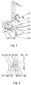
- Fig. 1 a base frame with removed container
- Fig. 2 an additional frame with spreading plate
- Fig. 3 a distributor
- Fig. 4 another distributor
- Fig. 5 a fan that works with the distributors according to 3 and 4 can be combined
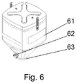
- Fig. 6 a container for attachment to the base frame according to Fig. 1
- Fig. 7 a divider made of the components of the Fig. 1, 2 and 6 is composed
- Fig. 8 this plate spreader on average
- Fig. 9 a spreader made of the components of the Fig. 1 . 3 and 6 is composed, on average
- Fig. 10 a spreader made of the components of the Fig. 1 . 3 . 5 and 6 is composed.
- Fig. 1 is attached to a base frame 11, a metering unit 12.
- the metering unit 12 essentially consists of a rotary valve 18, each cell of the cell wheel can accommodate a certain volume of seed. In one revolution of the cell wheel thus a quantity of seed, which corresponds to this volume multiplied by the number of cells passed through. So that no seed without active dosage passes the cell wheels, two scraper brooms 17 are provided.
- the rotary valve 18 is driven by a geared motor 19; by changing the speed of the geared motor 19, the flow through the rotary valve 18 can be adjusted.
- the dosing unit 12 has a connection 13 at the top (see also FIG Fig. 1 ) for a container 61 (see also Fig. 6 ) on.
- the container 61 in turn has a connection opening 63 which is connected to the connection 13 is adjusted (see Fig. 8 ). In this way, containers of different capacity can be mounted on the base frame 11.
- the container 61 has, as usual, an emptying opening 62.
- an agitator 64 is provided above the dosing unit 12.
- the metering unit 12 has at the bottom an outlet 14, from which the metered material emerges.
- the outlet 14 has a flange 14 '(see Fig. 1 ) with threaded bolts, are screwed to the nuts 35.
- an additional frame 21 (see FIG Fig. 2 ) are connected.
- the base frame 11 (see Fig. 1 ) a quick release 15, which with a counterpart 25 (see Fig. 2 ) cooperates on the additional frame 21.
- the additional frame 21 is therefore removable very quickly.
- a spreading plate 22 is mounted with throwing blades 27.
- the spreading plate 22 is together with the throwing blades 27 by a motor 30 (see Fig. 8 ). By changing the rotational speed of the motor 30, the throwing width changes.
- a collecting hopper 23 is provided.
- the upper opening 24 (see Fig. 2 ) of the collecting funnel 23 is at the outlet 14 (see Fig. 8 ) of the rotary valve 18 adapted.
- the opening 24 (see Fig. 2 ) has a flange 36 which has two slots 37.
- the Auferieticiantician consists of a funnel-shaped element 28 which is mounted pivotably about its vertical axis in a carrier 45.
- the carrier 45 has a flange 41 (see Fig. 2 ) with threaded bolts, are screwed onto the nuts 42.
- the threaded bolts pass through bores 43 (see FIG Fig. 1 ) in the base frame 11, whereby by tightening the hand nuts 42 of the carrier 45 (see Fig. 8 ) is fixed.
- the adjustment lever 29 can by means of a hand screw 40 in a slot 44 (see Fig. 1 ) of the base frame 11 are fixed.
- the additional frame 21 After loosening the quick release 15 (see Fig. 1 ) can therefore the additional frame 21 (see Fig. 8 ) are pivoted down so that the funnel-shaped element 28 is accessible.
- the material passed through can be collected and weighed very easily, so that the desired metering amount (in kg / min or kg / h) can be easily adjusted precisely by changing the speed of the geared motor 19.
- the axis 16 '(see Fig. 2 . 7 and 8th ) are removed.
- the elements for the Tellerstreuer can be easily removed:
- the additional frame 21 can be removed after loosening the quick fasteners 15 (and possibly after removing the axes 16 '), and the collecting hopper 23 and the Aufpreffigever ein can be removed after loosening a total of five nuts.
- the manifolds 32, 32a at the upper opening 34 a flange 36 with slots 37 which the flange 36 (see Fig. 2 ) of the collecting funnel 23 corresponds exactly.
- the manifolds 32, 32a can therefore also with the nuts 35 (see Fig. 1 ).
- the number of outlets of the manifolds 32, 32a is arbitrary, in the 3 and 4 For example, only six or two outlets are shown.
- the manifolds 32, 32a share the of the rotary valve 18 (see Fig. 8 ) passed through material in partial streams, in this example in six or two partial streams, on. From the distributor 32, 32a (see Fig. 3 and 4 ) then go according to the number of partial flows six or two hose lines away, through which the seed is further promoted.
- the distributors 32, 32a can be opened in the middle by means of quick-release fasteners 38.
- delivery through the tubing may be accomplished by a blower 51 (see Fig. 5 ), which - as in the 3 and 4 Seen - behind the manifold 32, 32 a is mounted to be supported.
- the blower 51 can be screwed to the base frame 11 (see Fig. 1 . 5 and 10 ).
Description
- Die vorliegende Erfindung betrifft einen Streuer mit einem Rahmen, der aus einem Grundrahmen und aus einem Zusatzrahmen besteht, wobei am Grundrahmen ein Behälter befestigt ist, wobei unter dem Behälter am Grundrahmen eine Dosiereinheit angeordnet ist, wobei unter dem Behälter am Zusatzrahmen ein Streuteller befestigt ist und wobei der Zusatzrahmen mittels eines Schnellverschlusses am Grundrahmen befestigt ist.
- Tellerstreuer mit einem Rahmen, an dem ein Behälter befestigt ist und an dem unter dem Behälter ein Sammeltrichter und ein Streuteller befestigt sind, sind bekannt und werden z. B. verwendet, um Saatgut auszubringen. Hier ist vor allem an Kleinstreuer gedacht, bei denen der Behälter z.B. 40 I oder 100 I Samen fasst. Unter dem Behälter befindet sich eine verstellbare Öffnung, damit die Streumenge eingestellt werden kann. Darunter befindet sich dann der Sammeltrichter, der das Saatgut auf einen Punkt des Streutellers aufgibt, von wo das Saatgut von (meist zwei) Wurfschaufeln verteilt wird. Durch Änderung der Drehzahl des Streutellers kann die Streubreite eingestellt werden.
- Ein Streuer der eingangs genannten Art ist
DE 3331169 A bekannt. Bei diesem Streuer hat der Behälter unten eine Auslauföffnung, deren Öffnungsweite zur Einstellung verschiedener Verteilermengen verändert werden kann, sodass man diese Auslauföffnung auch als Dosiereinheit bezeichnen könnte. - Bekannt sind auch so genannte pneumatische Sägeräte, mit denen während der Bodenbearbeitung gleichzeitig auch Saatgut ausgebracht wird. Bei diesen Geräten befindet sich unter dem Behälter eine Zellenradschleuse, um eine exakte Dosierung zu gewährleisten. Unter der Zellenradschleuse befindet sich ein Verteiler. Die einzelnen Zellenräder der Zellenradschleuse dosieren jeweils in einen eigenen Teilbereich des Verteilers. Je nach Ausführung der Zellenradschleuse und des Verteilers ergeben sich verschiedene Anzahlen von Teilströmen, z.B. 2, 4 oder 6. Infolge der Zellenradschleuse sind die Teilströme relativ konstant und relativ genau gleich groß. Von dem Verteiler führen Schläuche (z.B. 2, 4 oder 6 Schläuche) zu Pralltellern, wo das Saatgut auftrifft und verteilt wird.
- Wenn gleichzeitig zur Bodenbearbeitung auch Saatgut ausgebracht wird, ist es besser, solch ein Sägerät zu verwenden, weil dieses im Vergleich zu Tellerstreuern das Saatgut gleichmäßiger verteilt, insbesondere weniger von Wind beeinflusst wird.
- Nachteilig sind vor allem für Kleinbetriebe die zusätzlichen Kosten, da ein Tellerstreuer in der Regel bereits vorhanden ist. Daher werden oft Tellerstreuer verwendet, wenn Saatgut parallel zur Bodenbearbeitung ausgebracht werden soll. Dadurch wird das Saatgut in den meisten Fällen aber nur unzureichend genau verteilt ausgebracht, was zu einer Ertragsminderung bzw. zu einer unnötig hohen Aussaatmenge führt.
- Es ist Aufgabe der vorliegenden Erfindung, hier Abhilfe zu schaffen.
- Gemäß der vorliegenden Erfindung ist daher bei einem Streuer der eingangs genannten Art vorgesehen, dass die Dosiereinheit eine Zellenradschleuse aufweist, die unten einen Auslass für einen Sammeltrichter aufweist, und dass der Sammeltrichter an diesem Auslass der Dosiereinheit befestigt ist. Durch das Vorsehen einer Dosiereinheit mit einer Zellenradschleuse wird ein einfacher Umbau des Tellerstreuers möglich, sodass er auch für ein Sägerät verwendbar ist. Als zusätzlicher Vorteil kommt hinzu, dass auch in der Funktion als Tellerstreuer wegen der Zellenradschleuse eine sehr exakte Dosierung erfolgt. Neben der exakten Dosierung ist auch die Möglichkeit der geschwindigkeitsabhängigen Regelung der Ausbringmenge möglich. Dabei wird die Drehzahl der Zellenradschleuse elektronisch in Abhängigkeit der Fahrgeschwindigkeit nachgeregelt, wodurch die ausgebrachte Menge an Saatgut pro Flächeneinheit immer konstant gehalten wird. Das Gerät wird dadurch zwar etwas teurer, aber das wird durch den Vorteil, dass es für ein Sägerät umgebaut werden kann und so die Kosten für ein weiteres Gerät eingespart werden können, mehr als wettgemacht. Weiters kann durch die genaue Ausbringung auch Saatgut eingespart werden, wodurch sich die Mehrkosten schnell amortisieren.
- Vorzugsweise ist der Zusatzrahmen am Grundrahmen um eine Achse schwenkbar gelagert, sodass er nach Lösen des Schnellverschlusses nach unten wegschwenkbar ist. Auf diese Weise ist es sehr einfach möglich, die Dosiermenge zu überprüfen bzw. einzustellen. Man kann dadurch den Streuteller nach unten wegklappen und die von der Dosiereinheit gelieferte Menge in einem darunter gehaltenen Behälter auffangen und dann abwägen. Um bei herkömmlichen Tellerstreuern die Dosiermenge exakt einzustellen, ist es nötig, den Kalibriervorgang mit der bei der Arbeit tatsächlich eingestellten Tellerdrehzahl durchzuführen, da durch die Luftverwirbelungen des Streutellers und der damit verbundenen Sogwirkung die Durchflussmenge in kg/min auch direkt von der Tellerdrehzahl abhängig ist. Dabei muss man die vom Streuteller weggeschleuderte Menge "einfangen", d.h. man muss einen Behälter (z. B. einen Sack) um den Streuteller herum positionieren und einigermaßen abdichten, was wesentlich umständlicher ist. Durch die aktive Dosierung des Saatguts bei der vorliegenden Erfindung ist keine Sogwirkung auf das Saatgut vorhanden. Dadurch kann der Kalibriervorgang bei stehendem (weggeklapptem) Streuteller durchgeführt werden, was sowohl einfacher als auch sicherer ist. Weiters ist auch bei Änderung der Arbeitsbreite und damit der Streutellerdrehzahl keine Änderung der Durchflussrate in kg/min gegeben - im Gegensatz zu herkömmlichen Tellerstreuern.
- Wie bereits erwähnt, ist es ein Vorteil des erfindungsgemäßen Tellerstreuers, dass er für ein Sägerät umgebaut werden kann. Es ist daher ein weiterer Gegenstand der Erfindung (in der Art "kit of parts"), dass ein Verteiler vorgesehen ist, der nach Entfernen des Zusatzrahmens und des Sammeltrichters an den Auslass der Dosiereinheit anschließbar ist. Der Zusatzrahmen mit dem Streuteller und der Sammeltrichter werden bei dieser Anwendung demontiert.
- Vorzugsweise ist der Verteiler mit einem Gebläse versehen. Dadurch wird eine zuverlässige Förderung des Streuguts durch die angeschlossenen Schlauchleitungen gewährleistet. Insbesondere bei kleineren Sägeräten kann aber auch eine Förderung ausschließlich durch Schwerkraft ausreichend sein. Dann ist das Gebläse entbehrlich.
- An Hand der beiliegenden Zeichnungen wird die vorliegende Erfindung näher erläutert. Es zeigt:
Fig. 1 einen Grundrahmen mit abgenommenem Behälter;Fig. 2 einen Zusatzrahmen mit Streuteller;Fig. 3 einen Verteiler;Fig. 4 einen anderen Verteiler;Fig. 5 ein Gebläse, das mit den Verteilern gemäßFig. 3 und 4 kombinierbar ist;Fig. 6 einen Behälter zur Befestigung am Grundrahmen gemäßFig. 1 ;Fig. 7 einen Tellerstreuer, der aus den Komponenten derFig. 1, 2 und6 zusammengesetzt ist;Fig. 8 diesen Tellerstreuer im Schnitt;Fig. 9 einen Streuer, der aus den Komponenten derFig. 1 ,3 und6 zusammengesetzt ist, im Schnitt; undFig. 10 einen Streuer, der aus den Komponenten derFig. 1 ,3 ,5 und6 zusammengesetzt ist. - Gemäß
Fig. 1 ist an einem Grundrahmen 11 eine Dosiereinheit 12 befestigt. Wie ausFig. 8 erkennbar, besteht die Dosiereinheit 12 im Wesentlichen aus einer Zellenradschleuse 18, wobei jede Zelle des Zellenrades ein bestimmtes Volumen an Saatgut aufnehmen kann. Bei einer Umdrehung des Zellenrades wird somit eine Menge an Saatgut, die diesem Volumen multipliziert mit der Anzahl der Zellen entspricht, durchgeschleust. Damit kein Saatgut ohne aktive Dosierung an den Zellenrädern vorbeiläuft, sind zwei Abstreifbesen 17 vorgesehen. Die Zellenradschleuse 18 wird durch einen Getriebemotor 19 angetrieben; durch Veränderung der Drehzahl des Getriebemotors 19 kann der Durchfluss durch die Zellenradschleuse 18 eingestellt werden. - Die Dosiereinheit 12 weist oben einen Anschluss 13 (siehe auch
Fig. 1 ) für einen Behälter 61 (siehe auchFig. 6 ) auf. Der Behälter 61 weist seinerseits eine Anschlussöffnung 63 auf, die an den Anschluss 13 angepasst ist (sieheFig. 8 ). Auf diese Weise können Behälter mit verschiedenem Fassungsvermögen auf dem Grundrahmen 11 montiert werden. Der Behälter 61 weist wie üblich eine Entleerungsöffnung 62 auf. - Damit das Material im Behälter 61 sicher in die Dosiereinheit 12 gelangt, ist über der Dosiereinheit 12 ein Rührwerk 64 vorgesehen.
- Die Dosiereinheit 12 hat unten einen Auslass 14, aus dem das dosierte Gut austritt. Der Auslass 14 hat einen Flansch 14' (siehe
Fig. 1 ) mit Gewindebolzen, an die Handmuttern 35 aufgeschraubt sind. - Erfindungsgemäß kann an den Grundrahmen 11 ein Zusatzrahmen 21 (siehe
Fig. 2 ) angeschlossen werden. Dazu hat der Grundrahmen 11 (sieheFig. 1 ) einen Schnellverschluss 15, der mit einem Gegenstück 25 (sieheFig. 2 ) am Zusatzrahmen 21 zusammenwirkt. Der Zusatzrahmen 21 ist daher sehr schnell demontierbar. - Auf dem Zusatzrahmen 21 ist ein Streuteller 22 mit Wurfschaufeln 27 montiert. Der Streuteller 22 wird samt den Wurfschaufeln 27 von einem Motor 30 (siehe
Fig. 8 ) angetrieben. Durch Ändern der Drehzahl des Motors 30 ändert sich die Wurfbreite. - Damit das Material auf einen Punkt des Streutellers 22 aufgebracht wird, ist ein Sammeltrichter 23 vorgesehen. Die obere Öffnung 24 (siehe
Fig. 2 ) des Sammeltrichters 23 ist dabei an den Auslass 14 (sieheFig. 8 ) der Zellenradschleuse 18 angepasst. Die Öffnung 24 (sieheFig. 2 ) hat einen Flansch 36, der zwei Schlitze 37 aufweist. Damit kann der Sammeltrichter 23 mit den Schlitzen 37 unter die Handmuttern 35 (sieheFig. 1 ) geschoben und durch Festdrehen der Handmuttern 35 fixiert werden. - Damit der Punkt, auf den das Gut auf den Streuteller 22 (siehe
Fig. 8 ) aufgegeben wird, verstellt werden kann, ist eine Auftreffpunktverstellung vorgesehen. Die Auftreffpunktverstellung besteht aus einem trichterförmigen Element 28, das um seine Vertikalachse verschwenkbar in einem Träger 45 montiert ist. Der Träger 45 weist einen Flansch 41 (sieheFig. 2 ) mit Gewindebolzen auf, auf die Handmuttern 42 aufgeschraubt sind. Bei montiertem Träger 45 gehen die Gewindebolzen durch Bohrungen 43 (sieheFig. 1 ) im Grundrahmen 11, wodurch durch Festschrauben der Handmuttern 42 der Träger 45 (sieheFig. 8 ) fixiert ist. Mittels eines Einstellhebels 29 kann er so verschwenkt werden, dass das aufgegebene Gut von den Wurfschaufeln 27 optimal weggeschleudert wird. Der Einstellhebel 29 kann mittels einer Handschraube 40 in einem Schlitz 44 (sieheFig. 1 ) des Grundrahmens 11 fixiert werden. - Zusätzlich zum Schnellverschluss 15 weisen der Zusatzrahmen 21 und der Grundrahmen 11 Öffnungen 16 auf, durch die eine Achse 16' (siehe
Fig. 2 ,7 und8 ) gesteckt ist. Nach Lösen des Schnellverschlusses 15 (sieheFig. 1 ) kann daher der Zusatzrahmen 21 (sieheFig. 8 ) nach unten geschwenkt werden, sodass das trichterförmige Element 28 zugänglich ist. In diesem Zustand kann das durchgeschleuste Material sehr einfach gesammelt und gewogen werden, sodass die gewünschte Dosiermenge (in kg/min oder kg/h) auf einfache Weise präzise durch Änderung der Drehzahl des Getriebemotors 19 eingestellt werden kann. Zum Demontieren des Zusatzrahmens 21 muss nach dem Lösen des Schnellverschlusses 15 (sieheFig. 1 ) natürlich auch die Achse 16' (sieheFig. 2 ,7 und8 ) entfernt werden. - Die Elemente für den Tellerstreuer lassen sich einfach entfernen: Der Zusatzrahmen 21 lässt sich nach Lösen der Schnellverschlüsse 15 (und gegebenenfalls nach Entfernen der Achsen 16') abnehmen, und der Sammeltrichter 23 und die Auftreffpunktverstellung lassen sich nach Lösen von insgesamt fünf Handmuttern entfernen. In diesem Zustand kann man dann Verteiler 32, 32a, wie sie in den
Fig. 3 und 4 dargestellt sind, an die Dosiereinheit 12 (sieheFig. 1 ) anschließen. Zu diesem Zweck weisen die Verteiler 32, 32a (sieheFig. 3 und 4 ) an der oberen Öffnung 34 einen Flansch 36 mit Schlitzen 37 auf, der dem Flansch 36 (sieheFig. 2 ) des Sammeltrichters 23 genau entspricht. Die Verteiler 32, 32a (sieheFig. 3 und 4 ) lassen sich also ebenfalls mit den Handmuttern 35 (sieheFig. 1 ) befestigen. Die Anzahl der Abgänge der Verteiler 32, 32a ist beliebig, in denFig. 3 und 4 sind lediglich beispielsweise sechs bzw. zwei Abgänge gezeigt. - Die Verteiler 32, 32a teilen das von der Zellenradschleuse 18 (siehe
Fig. 8 ) durchgeschleuste Material in Teilströme, in diesem Beispiel in sechs bzw. zwei Teilströme, auf. Vom Verteiler 32, 32a (sieheFig. 3 und 4 ) gehen dann entsprechend der Anzahl der Teilströme sechs oder zwei Schlauchleitungen weg, durch die das Saatgut weitergefördert wird. - Um hier eine Kalibrierung durchführen zu können, können die Verteiler 32, 32a in der Mitte mittels Schnellverschlüssen 38 geöffnet werden.
- Wenn gewünscht kann die Förderung durch die Schlauchleitungen durch ein Gebläse 51 (siehe
Fig. 5 ), das - wie in denFig. 3 und 4 gesehen - hinter dem Verteiler 32, 32a montiert wird, unterstützt werden. Das Gebläse 51 kann am Grundrahmen 11 angeschraubt werden (sieheFig. 1 ,5 und10 ). - Man kann also z.B. folgende Elemente anbieten:
- Tellerstreuer
- Verteiler für einen Teilstrom ohne Gebläse
- Verteiler für einen Teilstrom mit Gebläse
- Verteiler für zwei Teilströme ohne Gebläse
- Verteiler für zwei Teilströme mit Gebläse
- Verteiler für drei Teilströme ohne Gebläse
- Verteiler für drei Teilströme mit Gebläse
- Verteiler für vier Teilströme ohne Gebläse
- Verteiler für vier Teilströme mit Gebläse
- Verteiler für sechs Teilströme ohne Gebläse
- Verteiler für sechs Teilströme mit Gebläse,
- und der Kunde sucht sich die für ihn passenden Elemente aus. Wenn er wenigstens ein Element zusätzlich zum Tellerstreuer benötigt, ist dies für den Kunden bereits günstiger, als wenn er verschiedene Geräte kaufen müsste.
Claims (4)
- Streuer mit einem Rahmen, der aus einem Grundrahmen (11) und aus einem Zusatzrahmen (21) besteht, wobei am Grundrahmen (11) ein Behälter (61) befestigt ist, wobei unter dem Behälter (61) am Grundrahmen (11) eine Dosiereinheit (12) angeordnet ist, wobei unter dem Behälter (61) am Zusatzrahmen (21) ein Streuteller (22) befestigt ist und wobei der Zusatzrahmen (21) mittels eines Schnellverschlusses (15, 25) am Grundrahmen (11) befestigt ist, dadurch gekennzeichnet, dass die Dosiereinheit (12) eine Zellenradschleuse (18) aufweist, die unten einen Auslass (14) für einen Sammeltrichter (23) aufweist, und dass der Sammeltrichter (23) an diesem Auslass (14) der Dosiereinheit (12) befestigt ist.
- Streuer nach Anspruch 1, dadurch gekennzeichnet, dass der Zusatzrahmen (21) am Grundrahmen (11) um eine Achse (16') schwenkbar gelagert ist, sodass er nach Lösen des Schnellverschlusses (15, 25) nach unten wegschwenkbar ist.
- Streuer nach Anspruch 1 oder 2, dadurch gekennzeichnet, dass ein Verteiler (32, 32a) vorgesehen ist, der nach Entfernen des Zusatzrahmens (21) und des Sammeltrichters (23) an den Auslass (14) der Dosiereinheit (12) anschließbar ist.
- Streuer nach Anspruch 3, dadurch gekennzeichnet, dass der Verteiler (32, 32a) mit einem Gebläse (51) versehen ist.
Priority Applications (1)
| Application Number | Priority Date | Filing Date | Title |
|---|---|---|---|
| PL16751583T PL3334268T3 (pl) | 2015-08-14 | 2016-08-12 | Rozsiewacz |
Applications Claiming Priority (2)
| Application Number | Priority Date | Filing Date | Title |
|---|---|---|---|
| ATGM50161/2015U AT14996U1 (de) | 2015-08-14 | 2015-08-14 | Streuer |
| PCT/EP2016/069272 WO2017029230A1 (de) | 2015-08-14 | 2016-08-12 | Streuer |
Publications (2)
| Publication Number | Publication Date |
|---|---|
| EP3334268A1 EP3334268A1 (de) | 2018-06-20 |
| EP3334268B1 true EP3334268B1 (de) | 2019-07-24 |
Family
ID=57123312
Family Applications (1)
| Application Number | Title | Priority Date | Filing Date |
|---|---|---|---|
| EP16751583.2A Active EP3334268B1 (de) | 2015-08-14 | 2016-08-12 | Streuer |
Country Status (6)
| Country | Link |
|---|---|
| US (1) | US20180235142A1 (de) |
| EP (1) | EP3334268B1 (de) |
| CN (1) | CN108135126A (de) |
| AT (1) | AT14996U1 (de) |
| PL (1) | PL3334268T3 (de) |
| WO (1) | WO2017029230A1 (de) |
Families Citing this family (9)
| Publication number | Priority date | Publication date | Assignee | Title |
|---|---|---|---|---|
| DE102016002827A1 (de) * | 2016-03-09 | 2017-09-14 | Rauch Landmaschinenfabrik Gmbh | Verteilmaschine |
| CN107155462A (zh) * | 2017-07-11 | 2017-09-15 | 山东源泉机械有限公司 | 一种单垄两行花生播种机 |
| US10736263B2 (en) * | 2018-04-26 | 2020-08-11 | Chapin Manufacturing, Inc. | Controlled-release spreader |
| CN109937665B (zh) * | 2019-03-31 | 2021-11-09 | 同心县金垚育种科技有限公司 | 一种均匀撒肥防结块农业离心圆盘式撒肥机 |
| CN112889431A (zh) * | 2021-01-21 | 2021-06-04 | 陈秀云 | 一种基于大数据用农业自动化农田施肥设备 |
| CN112956313A (zh) * | 2021-01-30 | 2021-06-15 | 张唯杰 | 一种可高效分苗的农业用播种车 |
| AU2022268919A1 (en) * | 2021-05-04 | 2023-12-07 | Unverferth Manufacturing Co., Inc. | Dry product spreader |
| CN113477353A (zh) * | 2021-05-24 | 2021-10-08 | 徐州中国矿大岩土工程新技术发展有限公司 | 一种植物种植用泥浆和营养基质破碎机及其使用方法 |
| CN114830897A (zh) * | 2022-04-18 | 2022-08-02 | 长沙环境保护职业技术学院 | 一种园林种植用土表快速埋肥装置 |
Family Cites Families (11)
| Publication number | Priority date | Publication date | Assignee | Title |
|---|---|---|---|---|
| DE2818227A1 (de) * | 1978-04-26 | 1979-11-08 | Amazonen Werke Dreyer H | Zentrifugalstreuer, insbesondere fuer duengemittel |
| DE3331169A1 (de) * | 1983-08-30 | 1985-03-14 | Amazonen-Werke H. Dreyer Gmbh & Co Kg, 4507 Hasbergen | Zentrifugalduengerstreuer zum anbau an den dreipunktkraftheber eines schleppers |
| DE3643853A1 (de) * | 1986-12-22 | 1988-06-30 | Amazonen Werke Dreyer H | Schleuderstreuer |
| DE3901523A1 (de) * | 1989-01-20 | 1990-07-26 | Amazonen Werke Dreyer H | Schleuderduengerstreuer |
| DE4109417A1 (de) * | 1991-03-22 | 1992-09-24 | Amazonen Werke Dreyer H | Schleuderduengerstreuer |
| EP0598494A3 (en) * | 1992-10-20 | 1994-06-15 | Peter William Allen | Apparatus and method for dispensing flowable material. |
| JP3783739B2 (ja) * | 1996-04-01 | 2006-06-07 | アグリテクノ矢崎株式会社 | 播種機の作溝装置 |
| CN100998281B (zh) * | 2006-12-23 | 2010-09-08 | 山西农业大学 | 多头异型螺旋槽小籽粒精少量排种装置 |
| US8857353B2 (en) * | 2011-06-24 | 2014-10-14 | Cnh Industrial Canada, Ltd. | System and method for controlling air flow to a metering system |
| US8893654B2 (en) * | 2012-10-15 | 2014-11-25 | Robert Todd Wisecarver | Rotary feed dispensing apparatus |
| CN204362567U (zh) * | 2014-12-03 | 2015-06-03 | 湖南农业大学 | 一种撒肥器 |
-
2015
- 2015-08-14 AT ATGM50161/2015U patent/AT14996U1/de unknown
-
2016
- 2016-08-12 US US15/752,604 patent/US20180235142A1/en not_active Abandoned
- 2016-08-12 PL PL16751583T patent/PL3334268T3/pl unknown
- 2016-08-12 CN CN201680057440.8A patent/CN108135126A/zh not_active Withdrawn
- 2016-08-12 EP EP16751583.2A patent/EP3334268B1/de active Active
- 2016-08-12 WO PCT/EP2016/069272 patent/WO2017029230A1/de active Application Filing
Non-Patent Citations (1)
| Title |
|---|
| None * |
Also Published As
| Publication number | Publication date |
|---|---|
| CN108135126A (zh) | 2018-06-08 |
| WO2017029230A1 (de) | 2017-02-23 |
| AT14996U1 (de) | 2016-10-15 |
| US20180235142A1 (en) | 2018-08-23 |
| EP3334268A1 (de) | 2018-06-20 |
| PL3334268T3 (pl) | 2020-03-31 |
Similar Documents
| Publication | Publication Date | Title |
|---|---|---|
| EP3334268B1 (de) | Streuer | |
| EP2695508B1 (de) | Verteilerkopf für eine Sä- und/oder Düngemaschine | |
| DE2835011B1 (de) | Schleuderstreuer,insbesondere fuer gekoernte Duengemittel | |
| DE102011054862A1 (de) | Bodenbearbeitungsgerät und Verfahren zur Einbringung von wasserspeicherndem Material und/oder Düngemittel und/oder Saatgut in den Erdboden | |
| DE4105045A1 (de) | Verfahren zum einstellen der dosierorgane einer verteilmaschine | |
| WO2021078581A1 (de) | Verteilerkopf fuer eine pneumatisch arbeitende verteilmaschine | |
| EP0079018B1 (de) | Gerät zum Verteilen von Gülle | |
| DE3050904C2 (de) | ||
| DE102007038510B4 (de) | Vorrichtung zum Dosieren und Verteilen von landwirtschaftlichen und kommunalen Schüttgütern | |
| EP0383071B1 (de) | Grossflächendüngerstreuer | |
| EP0559242B1 (de) | Schleuderdüngerstreuer | |
| EP3508047A1 (de) | Anordnung zum ausbringen von streugut auf landwirtschaftlichen flächen | |
| EP0433562A2 (de) | Schleuderdüngerstreuer | |
| DE102004038258B4 (de) | Pneumatische Verteilmaschine | |
| DE3419191C2 (de) | Verteilmaschine, insbesondere Drillmaschine | |
| DE4001113A1 (de) | Verteileinrichtung fuer guelle | |
| EP2878187B1 (de) | Vorrichtung zum gezielten Ausbringen von Streugut, wie Saatgut | |
| WO2011095192A1 (de) | Landwirtschaftliche vorrichtung | |
| EP1836887B1 (de) | Sämaschine | |
| EP3205195A1 (de) | Einheit zur entnahme einer probe an verteilgut aus einer verteilmaschine sowie pneumatische verteilmaschine und aufnahmeeinrichtung einer solchen einheit | |
| DE3821738A1 (de) | Pneumatikduengerstreuer | |
| EP0901748A1 (de) | Verfahren zum Einsatz eines Zentrifugalstreuers | |
| DE10238395A1 (de) | Verteilmaschine | |
| DD267407A5 (de) | Vorrichtung zum inkrustieren und pillieren kornfoermiger materialien | |
| DE3911584A1 (de) | Schleuderduengerstreuer |
Legal Events
| Date | Code | Title | Description |
|---|---|---|---|
| STAA | Information on the status of an ep patent application or granted ep patent |
Free format text: STATUS: THE INTERNATIONAL PUBLICATION HAS BEEN MADE |
|
| PUAI | Public reference made under article 153(3) epc to a published international application that has entered the european phase |
Free format text: ORIGINAL CODE: 0009012 |
|
| STAA | Information on the status of an ep patent application or granted ep patent |
Free format text: STATUS: REQUEST FOR EXAMINATION WAS MADE |
|
| 17P | Request for examination filed |
Effective date: 20180313 |
|
| AK | Designated contracting states |
Kind code of ref document: A1 Designated state(s): AL AT BE BG CH CY CZ DE DK EE ES FI FR GB GR HR HU IE IS IT LI LT LU LV MC MK MT NL NO PL PT RO RS SE SI SK SM TR |
|
| AX | Request for extension of the european patent |
Extension state: BA ME |
|
| DAV | Request for validation of the european patent (deleted) | ||
| DAX | Request for extension of the european patent (deleted) | ||
| RIC1 | Information provided on ipc code assigned before grant |
Ipc: F02B 19/10 20060101ALI20181221BHEP Ipc: F02M 21/02 20060101AFI20181221BHEP Ipc: F02B 19/12 20060101ALI20181221BHEP |
|
| GRAP | Despatch of communication of intention to grant a patent |
Free format text: ORIGINAL CODE: EPIDOSNIGR1 |
|
| STAA | Information on the status of an ep patent application or granted ep patent |
Free format text: STATUS: GRANT OF PATENT IS INTENDED |
|
| RIC1 | Information provided on ipc code assigned before grant |
Ipc: A01C 17/00 20060101ALI20190117BHEP Ipc: A01C 7/10 20060101AFI20190117BHEP |
|
| INTG | Intention to grant announced |
Effective date: 20190204 |
|
| GRAS | Grant fee paid |
Free format text: ORIGINAL CODE: EPIDOSNIGR3 |
|
| GRAA | (expected) grant |
Free format text: ORIGINAL CODE: 0009210 |
|
| STAA | Information on the status of an ep patent application or granted ep patent |
Free format text: STATUS: THE PATENT HAS BEEN GRANTED |
|
| AK | Designated contracting states |
Kind code of ref document: B1 Designated state(s): AL AT BE BG CH CY CZ DE DK EE ES FI FR GB GR HR HU IE IS IT LI LT LU LV MC MK MT NL NO PL PT RO RS SE SI SK SM TR |
|
| REG | Reference to a national code |
Ref country code: GB Ref legal event code: FG4D Free format text: NOT ENGLISH |
|
| REG | Reference to a national code |
Ref country code: CH Ref legal event code: EP |
|
| REG | Reference to a national code |
Ref country code: DE Ref legal event code: R096 Ref document number: 502016005712 Country of ref document: DE |
|
| REG | Reference to a national code |
Ref country code: AT Ref legal event code: REF Ref document number: 1157053 Country of ref document: AT Kind code of ref document: T Effective date: 20190815 |
|
| REG | Reference to a national code |
Ref country code: IE Ref legal event code: FG4D Free format text: LANGUAGE OF EP DOCUMENT: GERMAN |
|
| REG | Reference to a national code |
Ref country code: NL Ref legal event code: MP Effective date: 20190724 |
|
| REG | Reference to a national code |
Ref country code: LT Ref legal event code: MG4D |
|
| PG25 | Lapsed in a contracting state [announced via postgrant information from national office to epo] |
Ref country code: FI Free format text: LAPSE BECAUSE OF FAILURE TO SUBMIT A TRANSLATION OF THE DESCRIPTION OR TO PAY THE FEE WITHIN THE PRESCRIBED TIME-LIMIT Effective date: 20190724 Ref country code: LT Free format text: LAPSE BECAUSE OF FAILURE TO SUBMIT A TRANSLATION OF THE DESCRIPTION OR TO PAY THE FEE WITHIN THE PRESCRIBED TIME-LIMIT Effective date: 20190724 Ref country code: PT Free format text: LAPSE BECAUSE OF FAILURE TO SUBMIT A TRANSLATION OF THE DESCRIPTION OR TO PAY THE FEE WITHIN THE PRESCRIBED TIME-LIMIT Effective date: 20191125 Ref country code: NO Free format text: LAPSE BECAUSE OF FAILURE TO SUBMIT A TRANSLATION OF THE DESCRIPTION OR TO PAY THE FEE WITHIN THE PRESCRIBED TIME-LIMIT Effective date: 20191024 Ref country code: BG Free format text: LAPSE BECAUSE OF FAILURE TO SUBMIT A TRANSLATION OF THE DESCRIPTION OR TO PAY THE FEE WITHIN THE PRESCRIBED TIME-LIMIT Effective date: 20191024 Ref country code: NL Free format text: LAPSE BECAUSE OF FAILURE TO SUBMIT A TRANSLATION OF THE DESCRIPTION OR TO PAY THE FEE WITHIN THE PRESCRIBED TIME-LIMIT Effective date: 20190724 Ref country code: SE Free format text: LAPSE BECAUSE OF FAILURE TO SUBMIT A TRANSLATION OF THE DESCRIPTION OR TO PAY THE FEE WITHIN THE PRESCRIBED TIME-LIMIT Effective date: 20190724 Ref country code: HR Free format text: LAPSE BECAUSE OF FAILURE TO SUBMIT A TRANSLATION OF THE DESCRIPTION OR TO PAY THE FEE WITHIN THE PRESCRIBED TIME-LIMIT Effective date: 20190724 |
|
| PG25 | Lapsed in a contracting state [announced via postgrant information from national office to epo] |
Ref country code: IS Free format text: LAPSE BECAUSE OF FAILURE TO SUBMIT A TRANSLATION OF THE DESCRIPTION OR TO PAY THE FEE WITHIN THE PRESCRIBED TIME-LIMIT Effective date: 20191124 Ref country code: GR Free format text: LAPSE BECAUSE OF FAILURE TO SUBMIT A TRANSLATION OF THE DESCRIPTION OR TO PAY THE FEE WITHIN THE PRESCRIBED TIME-LIMIT Effective date: 20191025 Ref country code: RS Free format text: LAPSE BECAUSE OF FAILURE TO SUBMIT A TRANSLATION OF THE DESCRIPTION OR TO PAY THE FEE WITHIN THE PRESCRIBED TIME-LIMIT Effective date: 20190724 Ref country code: AL Free format text: LAPSE BECAUSE OF FAILURE TO SUBMIT A TRANSLATION OF THE DESCRIPTION OR TO PAY THE FEE WITHIN THE PRESCRIBED TIME-LIMIT Effective date: 20190724 Ref country code: LV Free format text: LAPSE BECAUSE OF FAILURE TO SUBMIT A TRANSLATION OF THE DESCRIPTION OR TO PAY THE FEE WITHIN THE PRESCRIBED TIME-LIMIT Effective date: 20190724 Ref country code: ES Free format text: LAPSE BECAUSE OF FAILURE TO SUBMIT A TRANSLATION OF THE DESCRIPTION OR TO PAY THE FEE WITHIN THE PRESCRIBED TIME-LIMIT Effective date: 20190724 |
|
| PG25 | Lapsed in a contracting state [announced via postgrant information from national office to epo] |
Ref country code: TR Free format text: LAPSE BECAUSE OF FAILURE TO SUBMIT A TRANSLATION OF THE DESCRIPTION OR TO PAY THE FEE WITHIN THE PRESCRIBED TIME-LIMIT Effective date: 20190724 |
|
| PG25 | Lapsed in a contracting state [announced via postgrant information from national office to epo] |
Ref country code: EE Free format text: LAPSE BECAUSE OF FAILURE TO SUBMIT A TRANSLATION OF THE DESCRIPTION OR TO PAY THE FEE WITHIN THE PRESCRIBED TIME-LIMIT Effective date: 20190724 Ref country code: DK Free format text: LAPSE BECAUSE OF FAILURE TO SUBMIT A TRANSLATION OF THE DESCRIPTION OR TO PAY THE FEE WITHIN THE PRESCRIBED TIME-LIMIT Effective date: 20190724 Ref country code: IT Free format text: LAPSE BECAUSE OF FAILURE TO SUBMIT A TRANSLATION OF THE DESCRIPTION OR TO PAY THE FEE WITHIN THE PRESCRIBED TIME-LIMIT Effective date: 20190724 Ref country code: RO Free format text: LAPSE BECAUSE OF FAILURE TO SUBMIT A TRANSLATION OF THE DESCRIPTION OR TO PAY THE FEE WITHIN THE PRESCRIBED TIME-LIMIT Effective date: 20190724 |
|
| PG25 | Lapsed in a contracting state [announced via postgrant information from national office to epo] |
Ref country code: SM Free format text: LAPSE BECAUSE OF FAILURE TO SUBMIT A TRANSLATION OF THE DESCRIPTION OR TO PAY THE FEE WITHIN THE PRESCRIBED TIME-LIMIT Effective date: 20190724 Ref country code: SK Free format text: LAPSE BECAUSE OF FAILURE TO SUBMIT A TRANSLATION OF THE DESCRIPTION OR TO PAY THE FEE WITHIN THE PRESCRIBED TIME-LIMIT Effective date: 20190724 Ref country code: CZ Free format text: LAPSE BECAUSE OF FAILURE TO SUBMIT A TRANSLATION OF THE DESCRIPTION OR TO PAY THE FEE WITHIN THE PRESCRIBED TIME-LIMIT Effective date: 20190724 Ref country code: LU Free format text: LAPSE BECAUSE OF NON-PAYMENT OF DUE FEES Effective date: 20190812 Ref country code: MC Free format text: LAPSE BECAUSE OF FAILURE TO SUBMIT A TRANSLATION OF THE DESCRIPTION OR TO PAY THE FEE WITHIN THE PRESCRIBED TIME-LIMIT Effective date: 20190724 Ref country code: CH Free format text: LAPSE BECAUSE OF NON-PAYMENT OF DUE FEES Effective date: 20190831 Ref country code: IS Free format text: LAPSE BECAUSE OF FAILURE TO SUBMIT A TRANSLATION OF THE DESCRIPTION OR TO PAY THE FEE WITHIN THE PRESCRIBED TIME-LIMIT Effective date: 20200224 Ref country code: LI Free format text: LAPSE BECAUSE OF NON-PAYMENT OF DUE FEES Effective date: 20190831 |
|
| REG | Reference to a national code |
Ref country code: BE Ref legal event code: MM Effective date: 20190831 |
|
| REG | Reference to a national code |
Ref country code: DE Ref legal event code: R097 Ref document number: 502016005712 Country of ref document: DE |
|
| PLBE | No opposition filed within time limit |
Free format text: ORIGINAL CODE: 0009261 |
|
| STAA | Information on the status of an ep patent application or granted ep patent |
Free format text: STATUS: NO OPPOSITION FILED WITHIN TIME LIMIT |
|
| PG2D | Information on lapse in contracting state deleted |
Ref country code: IS |
|
| PG25 | Lapsed in a contracting state [announced via postgrant information from national office to epo] |
Ref country code: IE Free format text: LAPSE BECAUSE OF NON-PAYMENT OF DUE FEES Effective date: 20190812 |
|
| 26N | No opposition filed |
Effective date: 20200603 |
|
| PG25 | Lapsed in a contracting state [announced via postgrant information from national office to epo] |
Ref country code: BE Free format text: LAPSE BECAUSE OF NON-PAYMENT OF DUE FEES Effective date: 20190831 Ref country code: SI Free format text: LAPSE BECAUSE OF FAILURE TO SUBMIT A TRANSLATION OF THE DESCRIPTION OR TO PAY THE FEE WITHIN THE PRESCRIBED TIME-LIMIT Effective date: 20190724 |
|
| GBPC | Gb: european patent ceased through non-payment of renewal fee |
Effective date: 20200812 |
|
| PG25 | Lapsed in a contracting state [announced via postgrant information from national office to epo] |
Ref country code: CY Free format text: LAPSE BECAUSE OF FAILURE TO SUBMIT A TRANSLATION OF THE DESCRIPTION OR TO PAY THE FEE WITHIN THE PRESCRIBED TIME-LIMIT Effective date: 20190724 |
|
| PG25 | Lapsed in a contracting state [announced via postgrant information from national office to epo] |
Ref country code: HU Free format text: LAPSE BECAUSE OF FAILURE TO SUBMIT A TRANSLATION OF THE DESCRIPTION OR TO PAY THE FEE WITHIN THE PRESCRIBED TIME-LIMIT; INVALID AB INITIO Effective date: 20160812 Ref country code: MT Free format text: LAPSE BECAUSE OF FAILURE TO SUBMIT A TRANSLATION OF THE DESCRIPTION OR TO PAY THE FEE WITHIN THE PRESCRIBED TIME-LIMIT Effective date: 20190724 |
|
| PG25 | Lapsed in a contracting state [announced via postgrant information from national office to epo] |
Ref country code: GB Free format text: LAPSE BECAUSE OF NON-PAYMENT OF DUE FEES Effective date: 20200812 |
|
| PG25 | Lapsed in a contracting state [announced via postgrant information from national office to epo] |
Ref country code: MK Free format text: LAPSE BECAUSE OF FAILURE TO SUBMIT A TRANSLATION OF THE DESCRIPTION OR TO PAY THE FEE WITHIN THE PRESCRIBED TIME-LIMIT Effective date: 20190724 |
|
| PGFP | Annual fee paid to national office [announced via postgrant information from national office to epo] |
Ref country code: AT Payment date: 20230831 Year of fee payment: 8 |
|
| PGFP | Annual fee paid to national office [announced via postgrant information from national office to epo] |
Ref country code: PL Payment date: 20230707 Year of fee payment: 8 Ref country code: FR Payment date: 20230712 Year of fee payment: 8 Ref country code: DE Payment date: 20230714 Year of fee payment: 8 |