EP3333648B1 - Vorrichtung zur steuerung von mindestens zwei elektronischen und/oder mechanischen funktionen eines tragbaren gegenstands - Google Patents
Vorrichtung zur steuerung von mindestens zwei elektronischen und/oder mechanischen funktionen eines tragbaren gegenstands Download PDFInfo
- Publication number
- EP3333648B1 EP3333648B1 EP17198321.6A EP17198321A EP3333648B1 EP 3333648 B1 EP3333648 B1 EP 3333648B1 EP 17198321 A EP17198321 A EP 17198321A EP 3333648 B1 EP3333648 B1 EP 3333648B1
- Authority
- EP
- European Patent Office
- Prior art keywords
- indexing plate
- control rod
- control stem
- position indexing
- arms
- Prior art date
- Legal status (The legal status is an assumption and is not a legal conclusion. Google has not performed a legal analysis and makes no representation as to the accuracy of the status listed.)
- Active
Links
Images






Classifications
-
- G—PHYSICS
- G04—HOROLOGY
- G04G—ELECTRONIC TIME-PIECES
- G04G21/00—Input or output devices integrated in time-pieces
-
- G—PHYSICS
- G04—HOROLOGY
- G04B—MECHANICALLY-DRIVEN CLOCKS OR WATCHES; MECHANICAL PARTS OF CLOCKS OR WATCHES IN GENERAL; TIME PIECES USING THE POSITION OF THE SUN, MOON OR STARS
- G04B37/00—Cases
- G04B37/08—Hermetic sealing of openings, joints, passages or slits
- G04B37/081—Complete encasings for wrist or pocket watches also comprising means for hermetic sealing of the winding stem and crown
-
- G—PHYSICS
- G04—HOROLOGY
- G04B—MECHANICALLY-DRIVEN CLOCKS OR WATCHES; MECHANICAL PARTS OF CLOCKS OR WATCHES IN GENERAL; TIME PIECES USING THE POSITION OF THE SUN, MOON OR STARS
- G04B19/00—Indicating the time by visual means
- G04B19/24—Clocks or watches with date or week-day indicators, i.e. calendar clocks or watches; Clockwork calendars
- G04B19/243—Clocks or watches with date or week-day indicators, i.e. calendar clocks or watches; Clockwork calendars characterised by the shape of the date indicator
- G04B19/247—Clocks or watches with date or week-day indicators, i.e. calendar clocks or watches; Clockwork calendars characterised by the shape of the date indicator disc-shaped
- G04B19/25—Devices for setting the date indicators manually
-
- G—PHYSICS
- G04—HOROLOGY
- G04B—MECHANICALLY-DRIVEN CLOCKS OR WATCHES; MECHANICAL PARTS OF CLOCKS OR WATCHES IN GENERAL; TIME PIECES USING THE POSITION OF THE SUN, MOON OR STARS
- G04B27/00—Mechanical devices for setting the time indicating means
- G04B27/02—Mechanical devices for setting the time indicating means by making use of the winding means
-
- G—PHYSICS
- G04—HOROLOGY
- G04B—MECHANICALLY-DRIVEN CLOCKS OR WATCHES; MECHANICAL PARTS OF CLOCKS OR WATCHES IN GENERAL; TIME PIECES USING THE POSITION OF THE SUN, MOON OR STARS
- G04B27/00—Mechanical devices for setting the time indicating means
- G04B27/002—The setting apparatus being crown shaped
-
- G—PHYSICS
- G04—HOROLOGY
- G04C—ELECTROMECHANICAL CLOCKS OR WATCHES
- G04C3/00—Electromechanical clocks or watches independent of other time-pieces and in which the movement is maintained by electric means
- G04C3/001—Electromechanical switches for setting or display
-
- G—PHYSICS
- G04—HOROLOGY
- G04C—ELECTROMECHANICAL CLOCKS OR WATCHES
- G04C3/00—Electromechanical clocks or watches independent of other time-pieces and in which the movement is maintained by electric means
- G04C3/001—Electromechanical switches for setting or display
- G04C3/005—Multiple switches
-
- G—PHYSICS
- G04—HOROLOGY
- G04G—ELECTRONIC TIME-PIECES
- G04G21/00—Input or output devices integrated in time-pieces
- G04G21/08—Touch switches specially adapted for time-pieces
Definitions
- the present invention relates to a device for controlling at least two electronic and/or mechanical functions for a small portable object. More specifically, the invention relates to such a device comprising a control rod provided with a mechanical position indexing device which makes it possible to make each electronic or mechanical function coincide with a distinct position of the control rod.
- the present invention relates to the field of control rods which equip small portable objects such as timepieces and which are arranged to control one or more electronic and/or mechanical functions of such objects.
- control rods of this type comprise a cylindrical portion whose length is substantially greater than the diameter and at one end of which located outside the portable object is fixed a crown allowing a user to operate the control rod and adjust the electronic or mechanical function(s).
- these rods control several functions, it is necessary to be able to make each given function coincide with a determined position of the control rod.
- this control rod comprises a cylindrical portion 202 terminated at its end located outside the portable object (not shown) which is equipped with it by an actuation ring 204.
- the cylindrical portion 202 of the control rod 200 is provided with a cam path 206 formed of three successive annular grooves 208a, 208b and 208c separated from each other by two beads 210a and 210b with substantially rounded profiles.
- the dimensions of the annular grooves 208a-208c are adapted to those of the elastic arms 212 of a spring 214, for example U-shaped, which project for example into the annular groove 208a of the cam path 206. It is understood that to pass the elastic arms 212 of the spring 214 of the annular groove 208a in the annular groove 208b, the user must exert on the control rod 200 a traction force greater than the force necessary for these elastic arms 212 to move away and slide on the bead 210a before closing on the annular groove 208b.
- a device for controlling a timepiece is known from the document CH 646 572 A3 .
- This control device comprises an external control member movable in rotation and in translation, fixed contact terminals connected to an electronic circuit and a switch mechanism comprising two movable members driven by the control member and cooperating with the terminals of contact.
- the present invention aims to remedy the problems mentioned above as well as others by providing a device for controlling at least two electronic and/or mechanical functions comprising a rod whose diameter is sufficiently small so that it can be used in particular in the field of watchmaking.
- the present invention provides a device for controlling at least two electronic or mechanical functions whose dimensions are contained, which makes it possible to install such a control device in a portable object of small dimensions such as in particular a wristwatch.
- the mechanical structure which makes it possible to index the position of the control rod is moved from the control rod itself towards a position indexing plate which is machined separately from the control rod.
- a position indexing plate which is machined separately from the control rod.
- Such a plate is relatively thin and also extends in a substantially horizontal plane, whereas, when the mechanical structure for indexing the position is provided on the control rod, it requires increasing the diameter of the control rod and therefore the height of the body of the portable object, so that the portable object is thicker, which we seek to avoid particularly in the field of timepieces.
- control rod and the indexing plate are not mounted inseparably makes it possible to guarantee the removable nature of the control device, which is advantageous in particularly in the case where the timepiece equipped with the control device according to the invention is of a certain price.
- the present invention proceeds from the general inventive idea which consists of transferring a mechanism for indexing the position of a control rod of at least two electronic and/or mechanical functions of a portable object of small dimensions such as a timepiece from this control rod to a plate machined separately from said control rod.
- a mechanism for indexing the position of a control rod of at least two electronic and/or mechanical functions of a portable object of small dimensions such as a timepiece By proceeding in this way, it is possible to reduce the diameter of the control rod and therefore concomitantly reduce the thickness of the middle of the portable object such as a timepiece.
- the indexing mechanism which typically takes the form of two cam paths cooperating with an elastic member, instead of being structured directly on the control rod, is made in a thin plate which constitutes a separate part from the control rod and which is mechanically coupled with the latter.
- the control rod does not have its indexing mechanism, its diameter can be reduced, and the position indexing plate according to the invention, due to its small thickness, does not result in a significant increase in the
- the direction from back to front is a rectilinear direction which extends horizontally along the longitudinal axis of symmetry XX of the control rod from the outer actuating ring towards the inside of the portable object equipped with the control device, parallel to a plane in which a bottom of the portable object extends. So the control rod will be pushed from rear to front, and will be pulled from front to rear.
- the vertical direction z is a direction which extends perpendicular to the plane in which the control rod extends.
- FIG 1 is a perspective view in the dissociated state of a device for controlling at least one electronic function of a portable object small dimensions like a wristwatch.
- this control device includes (see figure 2 ) a lower frame 2 for example made of an injected plastic material or of a non-magnetic metallic material such as brass.
- This lower frame 2 serves as a cradle for a control rod 4 of preferably elongated and substantially cylindrical shape, provided with a longitudinal axis of symmetry XX (see Figure 3 ).
- This control rod 4 is arranged to slide back and forth and back to front along its longitudinal axis of symmetry XX , and/or to rotate around this same longitudinal axis of symmetry XX in clockwise and counterclockwise directions. .
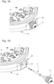
- control rod 4 At a rear end 6 which will be located outside the portable object once it is equipped with a control device 1, the control rod 4 will receive an actuation ring 8 (see Figure 18 ).
- control rod 4 At a front end 10 which will be located inside the control device 1 once it is assembled, the control rod 4 has a section 12, for example square, and successively receives a magnetic assembly 14 and a plain bearing 16.
- the magnetic assembly 14 comprises a bipolar or multipolar magnetic ring 18 and a support ring 20 on which the magnetic ring 18 is typically fixed by gluing (see figure 4 ).
- the support ring 20 is a part of generally cylindrical shape. As visible on the figure 5 , the support ring 20 has, from the rear towards the front, a first section 22a of a first external diameter D1 on which the magnetic ring 18 is engaged, and a second section 22b of a second external diameter D2 greater than the first external diameter D1 and which delimits a shoulder 24 against which the magnetic ring 18 bears.
- the first section 22a of the support ring 20 is pierced with a square hole 26 which is adapted in shape and dimension to the square section 12 of the control rod 4 and forms with this control rod 4 a pinion type system flowing.
- the support ring 20 and the ring magnet 18 remain stationary when the control rod 4 is slid axially.
- the control rod 4 drives the support ring 20 and the magnetized ring 18 in rotation when this control rod 4 is rotated.
- the plain bearing 16 defines (see figure 5 ) a cylindrical housing 28 whose first internal diameter D3 is very slightly greater than the diameter of the circle in which the square section 12 of the control rod 4 fits in order to allow this control rod 4 to slide axially and/or to rotate inside this cylindrical housing 28.
- the plain bearing 16 thus guarantees perfect axial guidance of the control rod 4.
- the square hole 26 made in the first section 22a of the support ring 20 is extended towards the front of the control device 1 by an annular hole 30 whose second interior diameter D4 is adjusted to the third exterior diameter D5 of the plain bearing 16.
- the support ring 20 is thus slipped freely into rotation on the plain bearing 16 and comes into axial abutment against this plain bearing 16, which guarantees the perfect axial alignment of these two parts and makes it possible to correct concentricity problems that a sliding pinion type coupling can pose.
- the plain bearing 16 is provided on its exterior surface with a circular flange 32 which projects into a first groove 34a and into a second groove 34b formed respectively in the lower frame 2 (see figure 2 ) and in an upper frame 36 (see Figure 6 ) arranged to cover the lower frame 2 and for example made of an injected plastic material or of a non-magnetic metallic material such as brass.
- a circular flange 32 which projects into a first groove 34a and into a second groove 34b formed respectively in the lower frame 2 (see figure 2 ) and in an upper frame 36 (see Figure 6 ) arranged to cover the lower frame 2 and for example made of an injected plastic material or of a non-magnetic metallic material such as brass.
- the magnetic assembly 14 and the plain bearing 16 described above are shown for purely illustrative purposes only.
- the plain bearing 16 for example made of steel or brass, is designed to prevent the control rod 4, for example made of steel, from rubbing against the lower 2 and upper 36 frames and causing wear of the material. plastic in which these two lower 2 and upper 36 frames are typically made.
- the plain bearing 16 is designed to prevent the control rod 4, for example made of steel, from rubbing against the lower 2 and upper 36 frames and causing wear of the material. plastic in which these two lower 2 and upper 36 frames are typically made.
- the magnetic ring 18 and the support ring 20 on which the magnetic ring 18 is fixed are provided for the case where the rotation of the control rod 4 is detected by a local variation of the magnetic field induced by the pivoting of the magnetic ring 18. It is however entirely possible to replace the magnetic assembly 14 for example by a sliding pinion which, depending on its position, will for example control the winding of a barrel spring or the setting to the time of a watch equipped with the control device 1.
- control rod 4 can have any type of section which deviates from a circular section, for example triangular or oval.
- the lower frame 2 and the upper frame 36, the union of which defines the external geometry of the control device 1, are for example of generally parallelepiped shape.
- the lower frame 2 forms a cradle which receives the control rod 4 (see figure 2 ).
- the lower frame 2 comprises towards the front a first receiving surface 38 of semi-circular profile which serves as a seat for the plain bearing 16 and in which is provided the first groove 34a which receives the circular flange 32.
- the immobilization of the plain bearing 16 both axially and in rotation is thus ensured.
- the lower frame 2 further comprises towards the rear a second receiving surface 40 whose semi-circular profile is centered on the longitudinal axis of symmetry XX of the control rod 4, but whose diameter is greater than that of this control rod 4. It is important to understand that the control rod 4 only bears on the second receiving surface 40 at the stage where the control device 1, assembled, is tested before being integrated into the portable object. At this stage of assembly, the control rod 4 is introduced into the control device 1 for testing purposes and extends horizontally being supported and guided axially by the plain bearing 16 on the side of its front end 10 and by the second receiving surface 40 on the side of its rear end 6.
- control rod 4 passes through a hole 42 made in the middle part 48 of the object portable in which it is guided and supported (see Figure 19 ), the middle part 48 being delimited downwards by a bottom 49.
- Third and fourth clearance surfaces 44a and 46a of semi-circular profile are also provided in the lower frame 2 and complementary clearance surfaces 44b and 46b (see Figure 6 ) are provided in the upper frame 36 to receive the magnetic assembly 14 consisting of the magnetic ring 18 and its support ring 20. It will be noted that the magnetic ring 18 and its support ring 20 are not in contact with the third and fourth clearance surfaces 44a, 46a and the complementary clearance surfaces 44b and 46b when the control device 1 is assembled and mounted in the portable object. We also note that the third clearance surface 44a and its corresponding complementary clearance surface 44b are delimited by a circular flange 50 for axial blocking of the magnetic assembly 14.
- the control rod 4 has a cylindrical section 52 whose diameter is between the diameter of the circle in which the square section 12 of the control rod 4 fits and the original diameter of a rear section 54 of this same control rod 4 at the end of which the actuating ring 8 is fixed.
- This cylindrical section 52 of reduced diameter forms a groove 56 in which is placed a plate 58 for indexing the position of the control rod 4 (see Figures 7A and 7B ).
- the position indexing plate 58 has a curved portion 60 which matches the profile of the cylindrical section 52 of reduced diameter and which allows the position indexing plate 58 to extend substantially horizontally.
- the position indexing plate 58 can for example be obtained by stamping a thin electrically conductive metal sheet.
- this position indexing plate 58 for example by molding a hard plastic material loaded with conductive particles.
- the engagement of the position indexing plate 58 in the groove 56 guarantees the coupling in translation from front to back and back to front between the control rod 4 and the position indexing plate 58.
- the position indexing plate 58 is free relative to the control rod 4 in a vertical direction z perpendicular to the longitudinal axis of symmetry XX of the control rod 4.
- the position indexing plate 58 is a substantially flat part and of general U shape.
- This position indexing plate 58 comprises two substantially rectilinear guide arms 62 which extend parallel to each other and which are connected to each other. one to the other by the curved portion 60. These two guide arms 62 are guided axially for example against two studs 64 provided in the lower frame 2. Guided by its two guide arms 62, the position indexing plate 58 slides along a rim 68 provided in the upper frame 36 and whose perimeter corresponds to that of the plate position indexing 58 (see Figure 6 ).
- the position indexing plate 58 also includes two fingers 66a, 66b which extend vertically downwards on either side of the two guide arms 62.
- the indexing plate of position 58 has the particular function of ensuring the translational guidance of the control rod 4 from front to rear and back to front.
- the fingers 66a, 66b they make it possible in particular to prevent the position indexing plate 58 from bracing when it moves in translation.
- Two openings 70 having a contour of approximately rectangular shape are provided in the guide arms 62 of the position indexing plate 58. These two openings 70 extend symmetrically on either side of the longitudinal axis of symmetry XX of the control rod 4.
- the sides of the two openings 70 closest to the longitudinal axis of symmetry XX of the control rod 4 have a cam path 72 of substantially sinusoidal shape formed of a first and a second hollow 74a and 74b separated by a vertex 76.
- the two openings 70 provided in the guide arms 62 are intended to receive the two ends 78 of a positioning spring 80 (see figure 8 ).
- This positioning spring 80 has a general U shape with two rods 82 which extend in a horizontal plane and which are connected together by a base 84. At their free end, the two rods 82 are extended by two arms 86 substantially rectilinear ones that stand vertically.
- the positioning spring 80 is intended to be mounted in the control device 1 from below the lower frame 2, so that the ends 78 of the arms 86 project into the openings 70 of the position indexing plate 58. It will be seen below that the cooperation between the position indexing plate 58 and the positioning spring 80 makes it possible to index the position of the control rod 4 between an unstable pushed position T0 and two stable positions T1 and T2.
- the position indexing plate 58 is coupled in translation with the control rod 4, but that it is free relative to the control rod 4 in the vertical direction z. It is therefore necessary to take measures to prevent the position indexing plate 58 from disengaging from the control rod 4 under normal conditions of use, for example under the effect of gravity.
- a spring 88 for limiting the movement of the position indexing plate 58 in the vertical direction z above and at a short distance from this position indexing plate 58.
- the movement limiting spring 88 is trapped between the lower frame 2 and the upper frame 36 of the control device 1, but is not, under normal conditions of use, in contact with the position indexing plate 58, which makes it possible to prevent Parasitic friction forces are exerted on the control rod 4 which would make it difficult to handle and cause a wear phenomenon.
- the movement limiting spring 88 is, however, sufficiently close to the position indexing plate 58 so that the latter cannot uncouple from the control rod 4 unintentionally.
- the movement limiting spring 88 comprises a substantially rectilinear central part 90 from the ends of which extend two pairs of elastic arms 92 and 94. These elastic arms 92 and 94 extend on either side of the part central 90 of the movement limitation spring 88, moving away upwards from the horizontal plane in which this central part 90 extends. These elastic arms 92 and 94, being compressed when the upper frame 36 is joined to the lower frame 2, give the movement limiting spring 88 its elasticity in the vertical direction z.
- pairs of elastic arms 92 and 94 are also provided a pair and, preferably, two pairs of rigid legs 96 which extend perpendicularly downwards on either side of the central part 90 of the movement limiting spring 88 These rigid legs 96 which come to bear on the lower frame 2 when the upper frame 36 is placed on the lower frame 2, guarantee compliance with a. minimum spacing between the position indexing plate 58 and the movement limiting spring 88 under normal operating conditions of the control device 1.
- the movement limitation spring 88 guarantees the removable nature of the control device 1. Indeed, in the absence of the movement limitation spring 88, the position indexing plate 58 would have to be made integral with the control rod 4 and, as a result, the control rod 4 could no longer be dismantled. However, if the control rod 4 cannot be dismantled, the movement of the timepiece equipped with the control device 1 cannot also be dismantled, which is not possible in particular in the case of a timepiece expensive.
- the control rod 4 slightly lifts the position indexing plate 58 against the elastic force of the movement limiting spring 88. By continuing to push forward the control rod 4, a moment when the position indexing plate 58 falls into the groove 56 under the effect of gravity. The control rod 4 and the position indexing plate 58 are then coupled in translation.
- a disengagement plate 98 is provided to allow the disassembly of the control rod 4 (see Figure 10 ).
- This dislocation plate 98 is of general H shape and comprises a straight segment 100 which extends parallel to the longitudinal axis of symmetry XX of the control rod 4 and to which a first and a second cross section 102 and 104 are attached The first cross section 102 is further provided at its two free ends with two legs 106 folded at a substantially right angle.
- the disengagement plate 98 is received in a housing 108 provided in the lower frame 2 and located under the control rod 4. This housing 108 communicates with the exterior of the device control device 1 via a hole 110 which opens into a lower face 112 of the control device 1 (see Figure 11 ).
- the control rod 4 From its stable rest position T1, the control rod 4 can be pushed forward into an unstable position T0 or pulled into a stable position T2. These three positions T0, T1 and T2 of the control rod 4 are indexed by cooperation between the position indexing plate 58 and the positioning spring 80. More precisely (see figure12A ), the stable rest position T1 corresponds to the position in which the ends 78 of the arms 86 of the positioning spring 80 project into the first recesses 74a of the two openings 70 provided in the guide arms 62 of the indexing plate of position 58. From this stable rest position T1, the control rod 4 can be pushed forward into an unstable position T0 (see Figure 12B ).
- the ends 78 of the arms 86 of the positioning spring 80 emerge from the first recesses 74a and follow a first ramp profile 114 which gradually deviates from the longitudinal axis of symmetry XX of the control rod 4 according to a first steep ⁇ slope.
- the user must therefore overcome a significant resistant effort.
- the ends 78 of the arms 86 engage on a second ramp profile 118 which extends the first ramp profile 114 with a second slope ⁇ less than the first slope ⁇ of the first ramp profile 114.
- the effort that the user must provide to continue to advance the control rod 4 drops suddenly and the user feels a click which indicates the transition of the control rod 4 between its position T1 and its position T0.
- the arms 86 of the positioning spring 80 continue to deviate slightly from their rest position and tend to want to move closer to each other again under the effect of their force elastic return opposed to the pushing force exerted by the user on the control rod 4.
- the arms 86 of the positioning spring 80 will spontaneously descend along the first ramp profile 114 and come again to be housed in the first recesses 74a of the two openings 70 provided in the guide arms 62 of the position indexing plate 58.
- the control rod 4 is thus automatically recalled from its unstable position T0 to its first stable position T1.
- First and second contact springs 120a and 120b are housed compressed in a first and second cavity 122a and 122b provided in the lower frame 2.
- These first and second contact springs 120a and 120b can be helical contact springs as desired, leaf springs or others.
- the two cavities 122a, 122b extend preferentially but not necessarily horizontally. Due to the fact that the two contact springs 120a, 120b are installed in the compressed state, the precision of their positioning is conditioned by the tolerance with which the lower frame 2 is manufactured. However, the precision with which the lower frame 2 is manufactured is greater than the manufacturing precision of these two first and second contact springs 120a, 120b. Therefore, the detection accuracy of the T0 position of the control rod 4 is high.
- one of the ends of the first and second contact springs 120a, 120b is curved by so as to form two contact tabs 124 which will come to bear on two first corresponding contact pads 126 provided on the surface of a sheet of flexible printed circuit 128.
- the first and second contact springs 120a, 120b are of the same length. However, preferably, one of the first and second cavities 122a, 122b will be longer than the other in particular to take into account tolerance problems (the difference in length between the two cavities 122a, 122b is a few tenths of a millimeter ). In this way, when the control rod 4 is pushed forward into its position T0, the finger 66a of the position indexing plate 58 which is in correspondence with the first contact spring 120a housed in the first cavity 122a the longest will come into contact with the latter and begin to compress it.
- the control rod 4 will continue to advance and the second finger 66b of the position indexing plate 58 will come into contact with the second contact spring 120b housed in the second shortest cavity 122b. At this time, the position indexing plate 58 will come into contact with the first and second contact springs 120a, 120b and the electric current will pass through the position indexing plate 58, which allows to detect the closing of the electrical contact between the first two contact springs 120a, 120b. Note that the fingers 66a, 66b of the position indexing plate 58 come into abutment contact with the first and second springs of contact 120a, 120b.
- the first contact spring 120a housed in the longest first cavity 122a is at the compressed state. Consequently, when the user releases the pressure on the control rod 4, this first contact spring 120a relaxes and forces the return of the control rod 4 from its unstable pushed position T0 to its first stable position T1.
- the first and second contact springs 120a, 120b therefore simultaneously play the role of electrical contact parts and elastic return means of the control rod 4 in its first stable position T1.
- third and Fourth contact springs 130a and 130b can be either helical contact springs, leaf springs or others.
- the third and fourth cavities 132a, 132b extend preferentially vertically for reasons of space requirement of the control device 1. As the position indexing plate 58 is electrically conductive, when the fingers 66a, 66b come into contact with the third and fourth contact springs 130a, 130b, the electric current passes through the position indexing plate 58 and the closing of the electrical contact T2 between these contact springs 130a, 130b is detected.
- the fingers 66a, 66b of the position indexing plate 58 also come into abutment contact with the third and fourth contact springs 130a, 130b, so that any risk frictional wear is avoided.
- the third and fourth contact springs 130a, 130b are capable of bending when the fingers 66a, 66b of the position indexing plate 58 strike them, and therefore of absorbing a possible lack of precision in the positioning of the position indexing plate 58.
- the third and fourth contact springs 130a, 130b are arranged to work in flexion.
- the fingers 66a, 66b of the position indexing plate 58 come into contact with the contact springs 130a, 130b along a large surface close to their points anchoring in the lower frame 2 and the upper frame 36.
- the proximity of the contact surface with the anchoring points of the contact springs 130a, 130b induces in these contact springs 130a, 130b shear stresses which can lead to premature wear and breakage of the latter.
- the contact springs 130a, 130b preferably present substantially at mid-height an increase in diameter 134 with which the fingers 66a, 66b of the position indexing plate 58 come into contact when the control rod 4 is pulled into its stable position T2 (see Figures 14A and 14B ).
- the third and fourth contact springs 130a, 130b are guided in two holes 136 provided in the upper frame 36 and come into contact with second contact pads 138 provided on the surface of the flexible printed circuit sheet 128 It is understood that, when the control rod 4 is pulled back into its stable position T2, the fingers 66a, 66b of the position indexing plate 58 come into contact with a reduced surface area with the third and fourth springs. contact springs 130a and 130b at their largest diameter 134, which allows these contact springs 130a, 130b to flex between their two anchoring points in the lower frame 2 and the upper frame 36.
- the sheet of flexible printed circuit 128 is fixed on a plate 140 located on the side of a dial of the portable object. It has in particular a cutout 142 adapted in shape and dimension to receive the upper frame 36.
- a portion 144 of the sheet of flexible printed circuit 128 remains free (see Figure 16 ).
- This free portion 144 of the sheet of flexible printed circuit 128 carries a plurality of electronic components 146 as well as third contact pads 148 on which two inductive sensors 150 are fixed.
- inductive sensor is meant a sensor which transforms a magnetic field which electrical voltage passes through it thanks to the induction phenomenon defined by the Lenz-Faraday law.
- it may be a Hall effect sensor or even a magnetoresistive component of the AMR (Anisostropic Magnetoresistance), GMR (Giant Magnetoresistance) or TMR (Tunneling Magnetoresistance) type.
- the free portion 144 of the sheet of flexible printed circuit 128 is connected to the remainder of the sheet of flexible printed circuit 128 by two strips 152 which allow the free portion 144 to be folded around the assembly of the upper frame 36 and the lower frame 2 , then fold down the free portion 144 against a lower surface 112 of the lower frame 2, so that the inductive sensors 150 penetrate into two housings 156 provided in the lower surface 112 of the lower frame 2.
- the inductive sensors 150 are precisely located under the magnetic ring 18, which guarantees reliable detection of the direction of rotation of the control rod 4.
- the assembly is covered by a holding plate 158 provided with one or even two elastic fingers 160 which press the inductive sensors 150 to the bottom of their housings 156 (see Figure 17B ).
- the retaining plate 158 is fixed on the plate 140 for example by means of two screws 162.
- the present invention is not limited to the embodiment which has just been described and that various simple modifications and variants can be envisaged by those skilled in the art without departing from the scope of the invention as defined. by the appended claims.
- the dimensions of the magnetic ring can be extended so as to make it correspond to a hollow cylinder.
- the position indexing plate 58 can only define two distinct positions, namely two stable positions or one stable position and one unstable position, or else it can define three or more distinct positions, namely at least three stable positions or at least two stable positions and one unstable position.
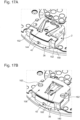
- FIG. 20A illustrates the case where the position indexing plate 58 defines two stable positions only.
- two openings 70-1 having an approximately rectangular contour are provided in the guide arms 62 of the position indexing plate 58. These two openings 70-1 extend symmetrically on either side. other of the longitudinal axis of symmetry XX of the control rod 4.
- the sides of the two openings 70-1 closest to the longitudinal axis of symmetry XX of the control rod 4 have a cam path 72-1 of substantially sinusoidal shape formed of a first and a second hollow 74a-1 and 74b-1 separated by a vertex 76-1.
- the two openings 70-1 provided in the guide arms 62 are intended to receive the two ends 78 of the arms of the positioning spring 80 so as to index the position of the control rod 4 between a first and a second stable position T1- 1 and T2-1.
- the first stable position T1-1 corresponds to the position in which the ends 78 of the arms 86 of the positioning spring 80 project into the first recesses 74a-1 of the two openings 70-1 provided in the guide arms 62 of the position indexing plate 58.
- the control rod 4 can be pulled back into a second stable position T2-1.
- the ends 78 of the arms 86 of the positioning spring 80 will pass, elastically deforming, from the first hollows 74a-1 to the second hollows 74b-1, crossing the vertices 76-1 of the two openings 70-1 provided in the guide arms 62 of the position indexing plate 58.
- FIG 21A illustrates the case where the indexing plate 58 defines a stable position T1-2 and an unstable position T0-2 only.
- two openings 70-2 having an approximately rectangular contour are provided in the guide arms 62 of the position indexing plate 58. These two openings 70-2 extend symmetrically on either side. other of the longitudinal axis of symmetry XX of the control rod 4.
- the sides of the two openings 70-2 closest to the longitudinal axis of symmetry XX of the control rod 4 have a cam path 72-2 formed a hollow 74a-2 followed by a ramp profile 114-2 which gradually deviates from the longitudinal axis of symmetry XX of the control rod 4 along a first steep slope ⁇ -2.
- the user To force the ends 78 of the arms 86 of the positioning spring 80 to come out of the recesses 74a-2 and to engage on the ramp profile 114-2 while moving away from each other, the user must therefore overcome a significant resistive effort. Arriving at a transition point 116-2, the ends 78 of the arms 86 engage on a second ramp profile 118-2 which extends the first ramp profile 114-2 with a second slope ⁇ -2 less than the first slope ⁇ -2 of the first ramp profile 114-2.
- the arms 86 of the positioning spring 80 will spontaneously lower the along the first ramp profile 114-2 and come to be housed again in the recesses 74a-2 of the two openings 70-2 provided in the guide arms 62 of the position indexing plate 58.
- the control rod 4 is thus automatically recalled from its unstable position T0-2 to its stable position T1-2.
Landscapes
- Physics & Mathematics (AREA)
- General Physics & Mathematics (AREA)
- Electric Clocks (AREA)
- Electromechanical Clocks (AREA)
Claims (11)
- Vorrichtung zur Steuerung von mindestens zwei elektronischen und/oder mechanischen Funktionen eines tragbaren Gegenstands mit kleinen Abmessungen, wobei die Vorrichtung eine Steuerungswelle (4) umfasst, die axial zwischen mindestens einer ersten und einer zweiten Position beweglich ist, wobei diese Steuerungswelle (4) an einem ersten Ende (6) mit einem Betätigungsorgan (8) versehen ist, und zu einem zweiten Ende (10) hin mit einer Positionsindexierplatte (58) versehen ist, die angeordnet ist, um mit einem elastischen Organ (80) zusammen zu wirken, um jede von der ersten und zweiten Position der Steuerungswelle (4) mit einer von den mechanischen oder elektronischen Funktionen übereinstimmen zu lassen, dadurch gekennzeichnet, dass sich die Indexierplatte (58) im Wesentlichen in einer horizontalen Ebene erstreckt, wobei die Positionsindexierplatte (58) zwei identische Kurvenscheibenwege (72) umfasst, mit denen zwei Arme (86) des elastischen Organs (80) zusammenwirken, um die erste und die zweite Position der Steuerungswelle (4) zu definieren.
- Vorrichtung nach Anspruch 1, dadurch gekennzeichnet, dass die beiden Kurvenscheibenwege (72) eine instabile Position und eine stabile Position der Steuerungswelle (4) definieren.
- Vorrichtung nach Anspruch 2, dadurch gekennzeichnet, dass die beiden Kurvenscheibenwege (72) jeweils eine Aussparung umfassen, welche die stabile Position der Steuerungswelle (4) definiert und aus der die Arme (86) des elastischen Organs (80) austreten, um in ein Rampenprofil einzugreifen, das die Arme (86) aus ihrer Ruheposition wegbewegt, und welche die instabile Position der Steuerungswelle (4) definiert.
- Vorrichtung nach Anspruch 3, dadurch gekennzeichnet, dass die Kurvenscheibenwege (72) ein erstes Rampenprofil (114) umfassen, das gemäß einer ersten Neigung α abweicht und das durch ein zweites Rampenprofil (118) verlängert wird, das gemäß einer zweiten Neigung β abweicht, die kleiner ist als die erste Neigung α des ersten Rampenprofils (114).
- Vorrichtung nach Anspruch 1, dadurch gekennzeichnet, dass die beiden Kurvenscheibenwege (72) eine erste und eine zweite stabile Position der Steuerungswelle (4) definieren.
- Vorrichtung nach Anspruch 5, dadurch gekennzeichnet, dass die beiden Kurvenscheibenwege (72) eine erste Aussparung umfassen, die von einer zweiten Aussparung durch einen Scheitelpunkt getrennt ist, wobei die erste und zweite Aussparung die erste und zweite stabile Position der Steuerungswelle (4) definieren, wobei die Arme (86) des elastischen Organs (80) durch Überwinden des Scheitelpunkts von der ersten Aussparung zur zweiten Aussparung und umgekehrt übergehen.
- Vorrichtung nach einem der Ansprüche 1 bis 6, dadurch gekennzeichnet, dass die Positionsindexierplatte (58) in einer in der Steuerungswelle (4) ausgeführten Nut (56) untergebracht ist.
- Vorrichtung nach Anspruch 7, dadurch gekennzeichnet, dass die Positionsindexierplatte (58) fest mit der Steuerungswelle (4) verbunden ist.
- Vorrichtung nach Anspruch 7, dadurch gekennzeichnet, dass die Positionsindexierplatte (58) abnehmbar mit der Steuerungswelle (4) gekoppelt ist.
- Vorrichtung nach Anspruch 9, dadurch gekennzeichnet, dass die Koppelung zwischen der Positionsindexierplatte (58) und der Steuerungswelle (4) eine elastische Koppelung ist, die angeordnet ist, um die Entkoppelung der Positionsindexierplatte (58) und der Steuerungswelle (4) unter normalen Nutzungsbedingungen zu verhindern.
- Vorrichtung nach Anspruch 10, dadurch gekennzeichnet, dass eine Feder (88) zur Begrenzung der Verschiebung der Positionsindexierplatte (58) gemäß einer vertikalen Richtung (z) oberhalb und in einem Abstand von der Positionsindexierplatte (58) angeordnet ist, sodass die Feder zur Begrenzung der Verschiebung (88) unter normalen Nutzungsbedingungen nicht in Kontakt mit der Positionsindexierplatte (58) ist, jedoch ausreichend nahe an der Positionsindexierplatte (58) ist, damit diese sich nicht unkontrolliert von der Steuerungswelle (4) entkoppeln kann.
Applications Claiming Priority (1)
| Application Number | Priority Date | Filing Date | Title |
|---|---|---|---|
| EP16202471.5A EP3333644A1 (de) | 2016-12-06 | 2016-12-06 | Vorrichtung zur steuerung von mindestens zwei elektronischen und/oder mechanischen funktionen eines tragbaren gegenstands |
Publications (2)
| Publication Number | Publication Date |
|---|---|
| EP3333648A1 EP3333648A1 (de) | 2018-06-13 |
| EP3333648B1 true EP3333648B1 (de) | 2024-04-24 |
Family
ID=57539042
Family Applications (2)
| Application Number | Title | Priority Date | Filing Date |
|---|---|---|---|
| EP16202471.5A Withdrawn EP3333644A1 (de) | 2016-12-06 | 2016-12-06 | Vorrichtung zur steuerung von mindestens zwei elektronischen und/oder mechanischen funktionen eines tragbaren gegenstands |
| EP17198321.6A Active EP3333648B1 (de) | 2016-12-06 | 2017-10-25 | Vorrichtung zur steuerung von mindestens zwei elektronischen und/oder mechanischen funktionen eines tragbaren gegenstands |
Family Applications Before (1)
| Application Number | Title | Priority Date | Filing Date |
|---|---|---|---|
| EP16202471.5A Withdrawn EP3333644A1 (de) | 2016-12-06 | 2016-12-06 | Vorrichtung zur steuerung von mindestens zwei elektronischen und/oder mechanischen funktionen eines tragbaren gegenstands |
Country Status (5)
| Country | Link |
|---|---|
| US (1) | US10921754B2 (de) |
| EP (2) | EP3333644A1 (de) |
| JP (2) | JP2018091839A (de) |
| KR (1) | KR102052802B1 (de) |
| CN (1) | CN108153136B (de) |
Families Citing this family (2)
| Publication number | Priority date | Publication date | Assignee | Title |
|---|---|---|---|---|
| EP3418813A1 (de) * | 2017-06-23 | 2018-12-26 | ETA SA Manufacture Horlogère Suisse | Bedienungsvorrichtung mit drücker-krone für ein kleines tragbares objekt |
| EP3910427A1 (de) | 2020-05-13 | 2021-11-17 | ETA SA Manufacture Horlogère Suisse | Befestigungskit |
Family Cites Families (34)
| Publication number | Priority date | Publication date | Assignee | Title |
|---|---|---|---|---|
| US1337217A (en) * | 1916-02-04 | 1920-04-20 | Nat Carbon Co Inc | Battery-switch |
| US2668200A (en) * | 1951-12-24 | 1954-02-02 | Grady O Glaze | Rotary multiple selector switch |
| US2948832A (en) * | 1958-07-23 | 1960-08-09 | Signal Stat Corp | Control switches for automotive vehicles |
| FR1310006A (de) * | 1961-10-13 | 1963-03-04 | ||
| US3151441A (en) * | 1962-11-30 | 1964-10-06 | Tsuzuki Akira | Time setting mechanism in watch |
| US3244822A (en) * | 1963-10-21 | 1966-04-05 | Gen Motors Corp | Combined push-pull rotary switch with rheostat and thermal circuit breaker structure |
| US3764762A (en) * | 1971-11-10 | 1973-10-09 | J Roeser | Electrical switch |
| US4034553A (en) * | 1975-07-11 | 1977-07-12 | Timex Corporation | Stem detent arrangement for wristwatch |
| JPS55119324A (en) | 1979-03-06 | 1980-09-13 | Suwa Seikosha Kk | Switching structure for watch |
| FR2469789A1 (fr) * | 1979-11-09 | 1981-05-22 | Radiotechnique | Bouton d'extremite pour commutateur a enfoncement |
| US4367380A (en) * | 1980-08-27 | 1983-01-04 | Oak Industries Inc. | Keyboard assembly and components therefor |
| US4329080A (en) * | 1980-09-15 | 1982-05-11 | Schlegel Corporation | Joint former |
| DE3113019C1 (de) | 1981-04-01 | 1982-10-07 | Gebrüder Junghans GmbH, 7230 Schramberg | Stellwellen-Stellvorrichtung fuer Minuten- und Stundenzeiger einer elektronischen Armbanduhr |
| DE3330109C2 (de) * | 1983-08-20 | 1986-01-02 | K.A. Schmersal Gmbh & Co, 5600 Wuppertal | Elektrischer Schalter |
| US4536095A (en) * | 1984-09-13 | 1985-08-20 | Timex Corporation | Crown setting switch for a wristwatch |
| CH664469GA3 (de) * | 1986-05-26 | 1988-03-15 | ||
| US4950845A (en) * | 1988-01-07 | 1990-08-21 | Kojima Press Industry Co., Ltd. | Switching device |
| JP3179520B2 (ja) * | 1991-07-11 | 2001-06-25 | 株式会社日立製作所 | 半導体装置の製造方法 |
| JP3355724B2 (ja) * | 1993-09-16 | 2002-12-09 | カシオ計算機株式会社 | 巻真位置決め構造 |
| CH686020B5 (fr) * | 1994-03-07 | 1996-06-14 | Smh Management Services Ag | Dispositif de commande a bouton-poussoir contacteur. |
| CH688495B5 (fr) * | 1995-09-04 | 1998-04-30 | Smh Management Services Ag | Pièce d'horlogerie comportant un mécanisme de commande à tige et à tirette. |
| US5742565A (en) * | 1996-05-21 | 1998-04-21 | Timex Corporation | Crown setting device for a timepiece |
| DE19632525C1 (de) * | 1996-08-13 | 1997-07-03 | Leica Camera Gmbh | Mehrstufiger Druckschalter für elektronische Geräte |
| JP3819123B2 (ja) * | 1997-08-29 | 2006-09-06 | アルゼ株式会社 | 押しボタン構造 |
| EP1435633B1 (de) * | 2002-12-31 | 2007-06-20 | ETA SA Manufacture Horlogère Suisse | Betätigungsvorrichtung mit mehreren axialen Stellungen für ein elektronisches Gerät |
| JP2006194834A (ja) * | 2005-01-17 | 2006-07-27 | Seiko Instruments Inc | 携帯時計 |
| TWI276132B (en) * | 2005-09-09 | 2007-03-11 | Hon Hai Prec Ind Co Ltd | A switch driver apparatus and electronic device employing the same |
| US8207466B2 (en) * | 2007-09-20 | 2012-06-26 | Siemens Industry, Inc. | Multi-position pushbutton with integral LED and actuator |
| JP5725065B2 (ja) * | 2013-03-21 | 2015-05-27 | カシオ計算機株式会社 | スイッチ装置および時計 |
| US20160233036A1 (en) * | 2013-12-09 | 2016-08-11 | Panasonic Intellectual Property Management Co., Ltd. | Switch device |
| EP3015925B1 (de) * | 2014-10-28 | 2020-07-15 | The Swatch Group Research and Development Ltd. | Optische positionserkennung eines uhrenkronenschafts |
| JP5983813B2 (ja) * | 2015-04-15 | 2016-09-06 | カシオ計算機株式会社 | スイッチ装置、時計 |
| US9911551B2 (en) * | 2015-09-30 | 2018-03-06 | Apple Inc. | Concealed apparatus for communicating with an electronic device |
| US10533908B1 (en) * | 2018-01-31 | 2020-01-14 | Honeywell Federal Manufacturing & Technologies, Llc | Activation component testing apparatus |
-
2016
- 2016-12-06 EP EP16202471.5A patent/EP3333644A1/de not_active Withdrawn
-
2017
- 2017-10-25 EP EP17198321.6A patent/EP3333648B1/de active Active
- 2017-11-01 US US15/800,819 patent/US10921754B2/en active Active
- 2017-11-22 JP JP2017224478A patent/JP2018091839A/ja active Pending
- 2017-12-05 KR KR1020170166124A patent/KR102052802B1/ko active Active
- 2017-12-05 CN CN201711266360.6A patent/CN108153136B/zh active Active
-
2019
- 2019-07-31 JP JP2019140989A patent/JP6884827B2/ja active Active
Also Published As
| Publication number | Publication date |
|---|---|
| EP3333644A1 (de) | 2018-06-13 |
| KR102052802B1 (ko) | 2019-12-05 |
| JP6884827B2 (ja) | 2021-06-09 |
| KR20180064998A (ko) | 2018-06-15 |
| EP3333648A1 (de) | 2018-06-13 |
| US20180157219A1 (en) | 2018-06-07 |
| CN108153136A (zh) | 2018-06-12 |
| US10921754B2 (en) | 2021-02-16 |
| CN108153136B (zh) | 2021-11-23 |
| HK1255454A1 (zh) | 2019-08-16 |
| JP2019207252A (ja) | 2019-12-05 |
| JP2018091839A (ja) | 2018-06-14 |
Similar Documents
| Publication | Publication Date | Title |
|---|---|---|
| EP3475768B1 (de) | Tragbarer gegenstand, der einen drehbaren steuerstab umfasst, dessen betätigung durch zwei induktionssensoren erkannt wird | |
| EP2657795B1 (de) | Befestigungsvorrichtung eines austauschbaren Armbands für Uhren | |
| EP3407144B1 (de) | Uhr, die eine verriegelungsvorrichtung für eine drucktaste umfasst | |
| EP3754436B1 (de) | Uhr, insbesondere taschenuhr, die mindestens mit einem deckel ausgestattet ist | |
| EP3418814B1 (de) | Bedienungsvorrichtung mit drücker-krone für ein kleines tragbares objekt | |
| EP3333647B1 (de) | Tragbarer gegenstand, der einen drehbaren steuerstab umfasst, dessen betätigung durch die messung einer magnetischen induktion erfasst wird | |
| EP3561608B1 (de) | Befestigungsleiste eines armbands an einer armbanduhr, die mit zwei einziehbaren drehzapfen ausgestattet ist | |
| EP2980658B1 (de) | Vorrichtung zum Zusammenbau und Regulieren einer Spirale | |
| CH712804B1 (fr) | Pièce d'horlogerie avec poussoir escamotable. | |
| EP3106933A1 (de) | Magnetischer schwenkeinrichtung einer welle in einem uhrwerk | |
| CH705605A2 (fr) | Dispositif de réglage de la longueur active d'un spiral. | |
| EP3333648A1 (de) | Vorrichtung zur steuerung von mindestens zwei elektronischen und/oder mechanischen funktionen eines tragbaren gegenstands | |
| EP2897002A2 (de) | Isolierter Schleppzeigermechanismus und mechanische Uhr, die einen Chronografenmechanismus mit einem solchen isolierten Schleppzeigermechanismus umfasst | |
| CH712574B1 (fr) | Dispositif pour la commande d'au moins deux fonctions électroniques et/ou mécaniques d'un objet portable. | |
| EP3483661A1 (de) | Betätigungswerkzeug eines korrektors, der zur ausstattung eines kleinen tragbaren objekts wie einer uhr gehört | |
| CH713321B1 (fr) | Dispositif de commande à couronne-poussoir pour un objet portable de petites dimensions. | |
| EP3182219B1 (de) | Uhr, die ein mit einem gelenkdeckel versehenes gehäuse und eine verriegelungsvorrichtung dieses deckels umfasst | |
| EP1960848B1 (de) | Hammer einer uhr | |
| CH712573B1 (fr) | Objet portable comprenant une tige de commande rotative dont l'actionnement est détecté par mesure d'une induction magnétique. | |
| EP3387495B1 (de) | Rattrapante-mechanismus | |
| CH712575B1 (fr) | Objet portable comprenant une tige de commande rotative dont l'actionnement est détecté au moyen de deux capteurs inductifs. | |
| EP1717459B1 (de) | Vorrichtung zum Befestigen eines Bauteils an einer Platte enthaltend eine Anordnung aus einem Käfig und einem Einsatz und Verfahren zum Herstellen einer solchen Anordnung | |
| CH706341B1 (fr) | Mécanisme de mise à l'heure et de remontage pour pièce d'horlogerie. | |
| CH700275A2 (fr) | Boîtier pour montre bracelet chronographe à leviers de commande des poussoirs. | |
| CH714923A2 (fr) | Barrette de fixation d'un bracelet à une montre munie de deux pivots rétractables. |
Legal Events
| Date | Code | Title | Description |
|---|---|---|---|
| PUAI | Public reference made under article 153(3) epc to a published international application that has entered the european phase |
Free format text: ORIGINAL CODE: 0009012 |
|
| STAA | Information on the status of an ep patent application or granted ep patent |
Free format text: STATUS: THE APPLICATION HAS BEEN PUBLISHED |
|
| AK | Designated contracting states |
Kind code of ref document: A1 Designated state(s): AL AT BE BG CH CY CZ DE DK EE ES FI FR GB GR HR HU IE IS IT LI LT LU LV MC MK MT NL NO PL PT RO RS SE SI SK SM TR |
|
| AX | Request for extension of the european patent |
Extension state: BA ME |
|
| STAA | Information on the status of an ep patent application or granted ep patent |
Free format text: STATUS: REQUEST FOR EXAMINATION WAS MADE |
|
| 17P | Request for examination filed |
Effective date: 20181213 |
|
| RBV | Designated contracting states (corrected) |
Designated state(s): AL AT BE BG CH CY CZ DE DK EE ES FI FR GB GR HR HU IE IS IT LI LT LU LV MC MK MT NL NO PL PT RO RS SE SI SK SM TR |
|
| STAA | Information on the status of an ep patent application or granted ep patent |
Free format text: STATUS: EXAMINATION IS IN PROGRESS |
|
| 17Q | First examination report despatched |
Effective date: 20190227 |
|
| P01 | Opt-out of the competence of the unified patent court (upc) registered |
Effective date: 20230701 |
|
| REG | Reference to a national code |
Ref country code: DE Ref legal event code: R079 Free format text: PREVIOUS MAIN CLASS: G04C0003000000 Ipc: G04B0027000000 Ref document number: 602017081235 Country of ref document: DE |
|
| GRAP | Despatch of communication of intention to grant a patent |
Free format text: ORIGINAL CODE: EPIDOSNIGR1 |
|
| STAA | Information on the status of an ep patent application or granted ep patent |
Free format text: STATUS: GRANT OF PATENT IS INTENDED |
|
| RIC1 | Information provided on ipc code assigned before grant |
Ipc: G04B 19/25 20060101ALI20231213BHEP Ipc: G04C 3/00 20060101ALI20231213BHEP Ipc: G04B 27/00 20060101AFI20231213BHEP |
|
| INTG | Intention to grant announced |
Effective date: 20240108 |
|
| GRAS | Grant fee paid |
Free format text: ORIGINAL CODE: EPIDOSNIGR3 |
|
| GRAA | (expected) grant |
Free format text: ORIGINAL CODE: 0009210 |
|
| STAA | Information on the status of an ep patent application or granted ep patent |
Free format text: STATUS: THE PATENT HAS BEEN GRANTED |
|
| AK | Designated contracting states |
Kind code of ref document: B1 Designated state(s): AL AT BE BG CH CY CZ DE DK EE ES FI FR GB GR HR HU IE IS IT LI LT LU LV MC MK MT NL NO PL PT RO RS SE SI SK SM TR |
|
| REG | Reference to a national code |
Ref country code: GB Ref legal event code: FG4D Free format text: NOT ENGLISH |
|
| RIN1 | Information on inventor provided before grant (corrected) |
Inventor name: BALMER, RAPHAEL Inventor name: SCHMUTZ, DAMIEN Inventor name: MEYER, PASCAL Inventor name: LAGORGETTE, PASCAL Inventor name: ZANESCO, VITTORIO |
|
| REG | Reference to a national code |
Ref country code: CH Ref legal event code: EP |
|
| REG | Reference to a national code |
Ref country code: DE Ref legal event code: R096 Ref document number: 602017081235 Country of ref document: DE |
|
| REG | Reference to a national code |
Ref country code: IE Ref legal event code: FG4D Free format text: LANGUAGE OF EP DOCUMENT: FRENCH |
|
| REG | Reference to a national code |
Ref country code: LT Ref legal event code: MG9D |
|
| REG | Reference to a national code |
Ref country code: NL Ref legal event code: MP Effective date: 20240424 |
|
| REG | Reference to a national code |
Ref country code: AT Ref legal event code: MK05 Ref document number: 1680259 Country of ref document: AT Kind code of ref document: T Effective date: 20240424 |
|
| PG25 | Lapsed in a contracting state [announced via postgrant information from national office to epo] |
Ref country code: NL Free format text: LAPSE BECAUSE OF FAILURE TO SUBMIT A TRANSLATION OF THE DESCRIPTION OR TO PAY THE FEE WITHIN THE PRESCRIBED TIME-LIMIT Effective date: 20240424 |
|
| PG25 | Lapsed in a contracting state [announced via postgrant information from national office to epo] |
Ref country code: NL Free format text: LAPSE BECAUSE OF FAILURE TO SUBMIT A TRANSLATION OF THE DESCRIPTION OR TO PAY THE FEE WITHIN THE PRESCRIBED TIME-LIMIT Effective date: 20240424 |
|
| PG25 | Lapsed in a contracting state [announced via postgrant information from national office to epo] |
Ref country code: IS Free format text: LAPSE BECAUSE OF FAILURE TO SUBMIT A TRANSLATION OF THE DESCRIPTION OR TO PAY THE FEE WITHIN THE PRESCRIBED TIME-LIMIT Effective date: 20240824 |
|
| PG25 | Lapsed in a contracting state [announced via postgrant information from national office to epo] |
Ref country code: BG Free format text: LAPSE BECAUSE OF FAILURE TO SUBMIT A TRANSLATION OF THE DESCRIPTION OR TO PAY THE FEE WITHIN THE PRESCRIBED TIME-LIMIT Effective date: 20240424 |
|
| PG25 | Lapsed in a contracting state [announced via postgrant information from national office to epo] |
Ref country code: FI Free format text: LAPSE BECAUSE OF FAILURE TO SUBMIT A TRANSLATION OF THE DESCRIPTION OR TO PAY THE FEE WITHIN THE PRESCRIBED TIME-LIMIT Effective date: 20240424 Ref country code: HR Free format text: LAPSE BECAUSE OF FAILURE TO SUBMIT A TRANSLATION OF THE DESCRIPTION OR TO PAY THE FEE WITHIN THE PRESCRIBED TIME-LIMIT Effective date: 20240424 |
|
| PG25 | Lapsed in a contracting state [announced via postgrant information from national office to epo] |
Ref country code: GR Free format text: LAPSE BECAUSE OF FAILURE TO SUBMIT A TRANSLATION OF THE DESCRIPTION OR TO PAY THE FEE WITHIN THE PRESCRIBED TIME-LIMIT Effective date: 20240725 |
|
| PG25 | Lapsed in a contracting state [announced via postgrant information from national office to epo] |
Ref country code: PT Free format text: LAPSE BECAUSE OF FAILURE TO SUBMIT A TRANSLATION OF THE DESCRIPTION OR TO PAY THE FEE WITHIN THE PRESCRIBED TIME-LIMIT Effective date: 20240826 |
|
| PG25 | Lapsed in a contracting state [announced via postgrant information from national office to epo] |
Ref country code: ES Free format text: LAPSE BECAUSE OF FAILURE TO SUBMIT A TRANSLATION OF THE DESCRIPTION OR TO PAY THE FEE WITHIN THE PRESCRIBED TIME-LIMIT Effective date: 20240424 |
|
| PG25 | Lapsed in a contracting state [announced via postgrant information from national office to epo] |
Ref country code: AT Free format text: LAPSE BECAUSE OF FAILURE TO SUBMIT A TRANSLATION OF THE DESCRIPTION OR TO PAY THE FEE WITHIN THE PRESCRIBED TIME-LIMIT Effective date: 20240424 |
|
| PG25 | Lapsed in a contracting state [announced via postgrant information from national office to epo] |
Ref country code: PL Free format text: LAPSE BECAUSE OF FAILURE TO SUBMIT A TRANSLATION OF THE DESCRIPTION OR TO PAY THE FEE WITHIN THE PRESCRIBED TIME-LIMIT Effective date: 20240424 |
|
| PG25 | Lapsed in a contracting state [announced via postgrant information from national office to epo] |
Ref country code: LV Free format text: LAPSE BECAUSE OF FAILURE TO SUBMIT A TRANSLATION OF THE DESCRIPTION OR TO PAY THE FEE WITHIN THE PRESCRIBED TIME-LIMIT Effective date: 20240424 |
|
| PG25 | Lapsed in a contracting state [announced via postgrant information from national office to epo] |
Ref country code: PT Free format text: LAPSE BECAUSE OF FAILURE TO SUBMIT A TRANSLATION OF THE DESCRIPTION OR TO PAY THE FEE WITHIN THE PRESCRIBED TIME-LIMIT Effective date: 20240826 Ref country code: PL Free format text: LAPSE BECAUSE OF FAILURE TO SUBMIT A TRANSLATION OF THE DESCRIPTION OR TO PAY THE FEE WITHIN THE PRESCRIBED TIME-LIMIT Effective date: 20240424 Ref country code: NO Free format text: LAPSE BECAUSE OF FAILURE TO SUBMIT A TRANSLATION OF THE DESCRIPTION OR TO PAY THE FEE WITHIN THE PRESCRIBED TIME-LIMIT Effective date: 20240724 Ref country code: LV Free format text: LAPSE BECAUSE OF FAILURE TO SUBMIT A TRANSLATION OF THE DESCRIPTION OR TO PAY THE FEE WITHIN THE PRESCRIBED TIME-LIMIT Effective date: 20240424 Ref country code: IS Free format text: LAPSE BECAUSE OF FAILURE TO SUBMIT A TRANSLATION OF THE DESCRIPTION OR TO PAY THE FEE WITHIN THE PRESCRIBED TIME-LIMIT Effective date: 20240824 Ref country code: HR Free format text: LAPSE BECAUSE OF FAILURE TO SUBMIT A TRANSLATION OF THE DESCRIPTION OR TO PAY THE FEE WITHIN THE PRESCRIBED TIME-LIMIT Effective date: 20240424 Ref country code: GR Free format text: LAPSE BECAUSE OF FAILURE TO SUBMIT A TRANSLATION OF THE DESCRIPTION OR TO PAY THE FEE WITHIN THE PRESCRIBED TIME-LIMIT Effective date: 20240725 Ref country code: FI Free format text: LAPSE BECAUSE OF FAILURE TO SUBMIT A TRANSLATION OF THE DESCRIPTION OR TO PAY THE FEE WITHIN THE PRESCRIBED TIME-LIMIT Effective date: 20240424 Ref country code: ES Free format text: LAPSE BECAUSE OF FAILURE TO SUBMIT A TRANSLATION OF THE DESCRIPTION OR TO PAY THE FEE WITHIN THE PRESCRIBED TIME-LIMIT Effective date: 20240424 Ref country code: BG Free format text: LAPSE BECAUSE OF FAILURE TO SUBMIT A TRANSLATION OF THE DESCRIPTION OR TO PAY THE FEE WITHIN THE PRESCRIBED TIME-LIMIT Effective date: 20240424 Ref country code: AT Free format text: LAPSE BECAUSE OF FAILURE TO SUBMIT A TRANSLATION OF THE DESCRIPTION OR TO PAY THE FEE WITHIN THE PRESCRIBED TIME-LIMIT Effective date: 20240424 Ref country code: RS Free format text: LAPSE BECAUSE OF FAILURE TO SUBMIT A TRANSLATION OF THE DESCRIPTION OR TO PAY THE FEE WITHIN THE PRESCRIBED TIME-LIMIT Effective date: 20240724 |
|
| PG25 | Lapsed in a contracting state [announced via postgrant information from national office to epo] |
Ref country code: DK Free format text: LAPSE BECAUSE OF FAILURE TO SUBMIT A TRANSLATION OF THE DESCRIPTION OR TO PAY THE FEE WITHIN THE PRESCRIBED TIME-LIMIT Effective date: 20240424 |
|
| PG25 | Lapsed in a contracting state [announced via postgrant information from national office to epo] |
Ref country code: EE Free format text: LAPSE BECAUSE OF FAILURE TO SUBMIT A TRANSLATION OF THE DESCRIPTION OR TO PAY THE FEE WITHIN THE PRESCRIBED TIME-LIMIT Effective date: 20240424 |
|
| PG25 | Lapsed in a contracting state [announced via postgrant information from national office to epo] |
Ref country code: CZ Free format text: LAPSE BECAUSE OF FAILURE TO SUBMIT A TRANSLATION OF THE DESCRIPTION OR TO PAY THE FEE WITHIN THE PRESCRIBED TIME-LIMIT Effective date: 20240424 |
|
| PG25 | Lapsed in a contracting state [announced via postgrant information from national office to epo] |
Ref country code: RO Free format text: LAPSE BECAUSE OF FAILURE TO SUBMIT A TRANSLATION OF THE DESCRIPTION OR TO PAY THE FEE WITHIN THE PRESCRIBED TIME-LIMIT Effective date: 20240424 Ref country code: SK Free format text: LAPSE BECAUSE OF FAILURE TO SUBMIT A TRANSLATION OF THE DESCRIPTION OR TO PAY THE FEE WITHIN THE PRESCRIBED TIME-LIMIT Effective date: 20240424 |
|
| REG | Reference to a national code |
Ref country code: DE Ref legal event code: R097 Ref document number: 602017081235 Country of ref document: DE |
|
| PG25 | Lapsed in a contracting state [announced via postgrant information from national office to epo] |
Ref country code: SM Free format text: LAPSE BECAUSE OF FAILURE TO SUBMIT A TRANSLATION OF THE DESCRIPTION OR TO PAY THE FEE WITHIN THE PRESCRIBED TIME-LIMIT Effective date: 20240424 |
|
| PG25 | Lapsed in a contracting state [announced via postgrant information from national office to epo] |
Ref country code: SM Free format text: LAPSE BECAUSE OF FAILURE TO SUBMIT A TRANSLATION OF THE DESCRIPTION OR TO PAY THE FEE WITHIN THE PRESCRIBED TIME-LIMIT Effective date: 20240424 Ref country code: SK Free format text: LAPSE BECAUSE OF FAILURE TO SUBMIT A TRANSLATION OF THE DESCRIPTION OR TO PAY THE FEE WITHIN THE PRESCRIBED TIME-LIMIT Effective date: 20240424 Ref country code: RO Free format text: LAPSE BECAUSE OF FAILURE TO SUBMIT A TRANSLATION OF THE DESCRIPTION OR TO PAY THE FEE WITHIN THE PRESCRIBED TIME-LIMIT Effective date: 20240424 Ref country code: EE Free format text: LAPSE BECAUSE OF FAILURE TO SUBMIT A TRANSLATION OF THE DESCRIPTION OR TO PAY THE FEE WITHIN THE PRESCRIBED TIME-LIMIT Effective date: 20240424 Ref country code: DK Free format text: LAPSE BECAUSE OF FAILURE TO SUBMIT A TRANSLATION OF THE DESCRIPTION OR TO PAY THE FEE WITHIN THE PRESCRIBED TIME-LIMIT Effective date: 20240424 Ref country code: CZ Free format text: LAPSE BECAUSE OF FAILURE TO SUBMIT A TRANSLATION OF THE DESCRIPTION OR TO PAY THE FEE WITHIN THE PRESCRIBED TIME-LIMIT Effective date: 20240424 |
|
| PLBE | No opposition filed within time limit |
Free format text: ORIGINAL CODE: 0009261 |
|
| STAA | Information on the status of an ep patent application or granted ep patent |
Free format text: STATUS: NO OPPOSITION FILED WITHIN TIME LIMIT |
|
| 26N | No opposition filed |
Effective date: 20250127 |
|
| PG25 | Lapsed in a contracting state [announced via postgrant information from national office to epo] |
Ref country code: SI Free format text: LAPSE BECAUSE OF FAILURE TO SUBMIT A TRANSLATION OF THE DESCRIPTION OR TO PAY THE FEE WITHIN THE PRESCRIBED TIME-LIMIT Effective date: 20240424 |
|
| PG25 | Lapsed in a contracting state [announced via postgrant information from national office to epo] |
Ref country code: MC Free format text: LAPSE BECAUSE OF FAILURE TO SUBMIT A TRANSLATION OF THE DESCRIPTION OR TO PAY THE FEE WITHIN THE PRESCRIBED TIME-LIMIT Effective date: 20240424 |
|
| PG25 | Lapsed in a contracting state [announced via postgrant information from national office to epo] |
Ref country code: BE Free format text: LAPSE BECAUSE OF NON-PAYMENT OF DUE FEES Effective date: 20241031 Ref country code: LU Free format text: LAPSE BECAUSE OF NON-PAYMENT OF DUE FEES Effective date: 20241025 |
|
| REG | Reference to a national code |
Ref country code: BE Ref legal event code: MM Effective date: 20241031 |
|
| PG25 | Lapsed in a contracting state [announced via postgrant information from national office to epo] |
Ref country code: SE Free format text: LAPSE BECAUSE OF FAILURE TO SUBMIT A TRANSLATION OF THE DESCRIPTION OR TO PAY THE FEE WITHIN THE PRESCRIBED TIME-LIMIT Effective date: 20240424 |
|
| PGFP | Annual fee paid to national office [announced via postgrant information from national office to epo] |
Ref country code: GB Payment date: 20250923 Year of fee payment: 9 |
|
| PGFP | Annual fee paid to national office [announced via postgrant information from national office to epo] |
Ref country code: FR Payment date: 20250923 Year of fee payment: 9 |
|
| PG25 | Lapsed in a contracting state [announced via postgrant information from national office to epo] |
Ref country code: IE Free format text: LAPSE BECAUSE OF NON-PAYMENT OF DUE FEES Effective date: 20241025 |
|
| REG | Reference to a national code |
Ref country code: CH Ref legal event code: U11 Free format text: ST27 STATUS EVENT CODE: U-0-0-U10-U11 (AS PROVIDED BY THE NATIONAL OFFICE) Effective date: 20251101 |
|
| PGFP | Annual fee paid to national office [announced via postgrant information from national office to epo] |
Ref country code: DE Payment date: 20250923 Year of fee payment: 9 |
|
| PGFP | Annual fee paid to national office [announced via postgrant information from national office to epo] |
Ref country code: CH Payment date: 20251101 Year of fee payment: 9 |
|
| PG25 | Lapsed in a contracting state [announced via postgrant information from national office to epo] |
Ref country code: IT Free format text: LAPSE BECAUSE OF FAILURE TO SUBMIT A TRANSLATION OF THE DESCRIPTION OR TO PAY THE FEE WITHIN THE PRESCRIBED TIME-LIMIT Effective date: 20240424 Ref country code: CY Free format text: LAPSE BECAUSE OF FAILURE TO SUBMIT A TRANSLATION OF THE DESCRIPTION OR TO PAY THE FEE WITHIN THE PRESCRIBED TIME-LIMIT; INVALID AB INITIO Effective date: 20171025 |
|
| PG25 | Lapsed in a contracting state [announced via postgrant information from national office to epo] |
Ref country code: HU Free format text: LAPSE BECAUSE OF FAILURE TO SUBMIT A TRANSLATION OF THE DESCRIPTION OR TO PAY THE FEE WITHIN THE PRESCRIBED TIME-LIMIT; INVALID AB INITIO Effective date: 20171025 |