EP3333647B1 - Tragbarer gegenstand, der einen drehbaren steuerstab umfasst, dessen betätigung durch die messung einer magnetischen induktion erfasst wird - Google Patents
Tragbarer gegenstand, der einen drehbaren steuerstab umfasst, dessen betätigung durch die messung einer magnetischen induktion erfasst wird Download PDFInfo
- Publication number
- EP3333647B1 EP3333647B1 EP17196387.9A EP17196387A EP3333647B1 EP 3333647 B1 EP3333647 B1 EP 3333647B1 EP 17196387 A EP17196387 A EP 17196387A EP 3333647 B1 EP3333647 B1 EP 3333647B1
- Authority
- EP
- European Patent Office
- Prior art keywords
- portable object
- control rod
- inductive sensor
- inductive
- frame
- Prior art date
- Legal status (The legal status is an assumption and is not a legal conclusion. Google has not performed a legal analysis and makes no representation as to the accuracy of the status listed.)
- Active
Links
Images





Classifications
-
- G—PHYSICS
- G04—HOROLOGY
- G04G—ELECTRONIC TIME-PIECES
- G04G21/00—Input or output devices integrated in time-pieces
-
- G—PHYSICS
- G04—HOROLOGY
- G04B—MECHANICALLY-DRIVEN CLOCKS OR WATCHES; MECHANICAL PARTS OF CLOCKS OR WATCHES IN GENERAL; TIME PIECES USING THE POSITION OF THE SUN, MOON OR STARS
- G04B47/00—Time-pieces combined with other articles which do not interfere with the running or the time-keeping of the time-piece
- G04B47/06—Time-pieces combined with other articles which do not interfere with the running or the time-keeping of the time-piece with attached measuring instruments, e.g. pedometer, barometer, thermometer or compass
-
- G—PHYSICS
- G04—HOROLOGY
- G04B—MECHANICALLY-DRIVEN CLOCKS OR WATCHES; MECHANICAL PARTS OF CLOCKS OR WATCHES IN GENERAL; TIME PIECES USING THE POSITION OF THE SUN, MOON OR STARS
- G04B3/00—Normal winding of clockworks by hand or mechanically; Winding up several mainsprings or driving weights simultaneously
- G04B3/04—Rigidly-mounted keys, knobs or crowns
- G04B3/046—Operation by rotation and axial movement with extra function of axial shift of operating element, e.g. crown combined with push button
-
- G—PHYSICS
- G01—MEASURING; TESTING
- G01B—MEASURING LENGTH, THICKNESS OR SIMILAR LINEAR DIMENSIONS; MEASURING ANGLES; MEASURING AREAS; MEASURING IRREGULARITIES OF SURFACES OR CONTOURS
- G01B7/00—Measuring arrangements characterised by the use of electric or magnetic techniques
- G01B7/003—Measuring arrangements characterised by the use of electric or magnetic techniques for measuring position, not involving coordinate determination
-
- G—PHYSICS
- G01—MEASURING; TESTING
- G01D—MEASURING NOT SPECIALLY ADAPTED FOR A SPECIFIC VARIABLE; ARRANGEMENTS FOR MEASURING TWO OR MORE VARIABLES NOT COVERED IN A SINGLE OTHER SUBCLASS; TARIFF METERING APPARATUS; MEASURING OR TESTING NOT OTHERWISE PROVIDED FOR
- G01D5/00—Mechanical means for transferring the output of a sensing member; Means for converting the output of a sensing member to another variable where the form or nature of the sensing member does not constrain the means for converting; Transducers not specially adapted for a specific variable
- G01D5/12—Mechanical means for transferring the output of a sensing member; Means for converting the output of a sensing member to another variable where the form or nature of the sensing member does not constrain the means for converting; Transducers not specially adapted for a specific variable using electric or magnetic means
- G01D5/14—Mechanical means for transferring the output of a sensing member; Means for converting the output of a sensing member to another variable where the form or nature of the sensing member does not constrain the means for converting; Transducers not specially adapted for a specific variable using electric or magnetic means influencing the magnitude of a current or voltage
- G01D5/20—Mechanical means for transferring the output of a sensing member; Means for converting the output of a sensing member to another variable where the form or nature of the sensing member does not constrain the means for converting; Transducers not specially adapted for a specific variable using electric or magnetic means influencing the magnitude of a current or voltage by varying inductance, e.g. by a movable armature
-
- G—PHYSICS
- G01—MEASURING; TESTING
- G01L—MEASURING FORCE, STRESS, TORQUE, WORK, MECHANICAL POWER, MECHANICAL EFFICIENCY, OR FLUID PRESSURE
- G01L5/00—Apparatus for, or methods of, measuring force, work, mechanical power, or torque, specially adapted for specific purposes
- G01L5/20—Apparatus for, or methods of, measuring force, work, mechanical power, or torque, specially adapted for specific purposes for measuring wheel side-thrust
-
- G—PHYSICS
- G01—MEASURING; TESTING
- G01P—MEASURING LINEAR OR ANGULAR SPEED, ACCELERATION, DECELERATION, OR SHOCK; INDICATING PRESENCE, ABSENCE, OR DIRECTION, OF MOVEMENT
- G01P13/00—Indicating or recording presence, absence, or direction, of movement
-
- G—PHYSICS
- G01—MEASURING; TESTING
- G01R—MEASURING ELECTRIC VARIABLES; MEASURING MAGNETIC VARIABLES
- G01R15/00—Details of measuring arrangements of the types provided for in groups G01R17/00 - G01R29/00, G01R33/00 - G01R33/26 or G01R35/00
- G01R15/14—Adaptations providing voltage or current isolation, e.g. for high-voltage or high-current networks
- G01R15/20—Adaptations providing voltage or current isolation, e.g. for high-voltage or high-current networks using galvano-magnetic devices, e.g. Hall-effect devices, i.e. measuring a magnetic field via the interaction between a current and a magnetic field, e.g. magneto resistive or Hall effect devices
- G01R15/202—Adaptations providing voltage or current isolation, e.g. for high-voltage or high-current networks using galvano-magnetic devices, e.g. Hall-effect devices, i.e. measuring a magnetic field via the interaction between a current and a magnetic field, e.g. magneto resistive or Hall effect devices using Hall-effect devices
-
- G—PHYSICS
- G01—MEASURING; TESTING
- G01R—MEASURING ELECTRIC VARIABLES; MEASURING MAGNETIC VARIABLES
- G01R15/00—Details of measuring arrangements of the types provided for in groups G01R17/00 - G01R29/00, G01R33/00 - G01R33/26 or G01R35/00
- G01R15/14—Adaptations providing voltage or current isolation, e.g. for high-voltage or high-current networks
- G01R15/20—Adaptations providing voltage or current isolation, e.g. for high-voltage or high-current networks using galvano-magnetic devices, e.g. Hall-effect devices, i.e. measuring a magnetic field via the interaction between a current and a magnetic field, e.g. magneto resistive or Hall effect devices
- G01R15/207—Constructional details independent of the type of device used
-
- G—PHYSICS
- G04—HOROLOGY
- G04B—MECHANICALLY-DRIVEN CLOCKS OR WATCHES; MECHANICAL PARTS OF CLOCKS OR WATCHES IN GENERAL; TIME PIECES USING THE POSITION OF THE SUN, MOON OR STARS
- G04B3/00—Normal winding of clockworks by hand or mechanically; Winding up several mainsprings or driving weights simultaneously
- G04B3/04—Rigidly-mounted keys, knobs or crowns
- G04B3/041—Construction of crowns for rotating movement; connection with the winding stem; winding stems
-
- G—PHYSICS
- G04—HOROLOGY
- G04C—ELECTROMECHANICAL CLOCKS OR WATCHES
- G04C3/00—Electromechanical clocks or watches independent of other time-pieces and in which the movement is maintained by electric means
- G04C3/001—Electromechanical switches for setting or display
-
- G—PHYSICS
- G04—HOROLOGY
- G04C—ELECTROMECHANICAL CLOCKS OR WATCHES
- G04C3/00—Electromechanical clocks or watches independent of other time-pieces and in which the movement is maintained by electric means
- G04C3/001—Electromechanical switches for setting or display
- G04C3/004—Magnetically controlled
Definitions
- the present invention relates to a portable object of small dimensions such as a timepiece comprising a rotary control rod for controlling at least one electronic or mechanical function of the portable object. More specifically, the invention relates to such a portable object, the actuation of the rotary control rod of which is detected by measuring a magnetic induction.
- the present invention relates to portable objects of small dimensions such as wristwatches which comprise a rotary control rod, the actuation of which makes it possible to control a mechanical or electronic function of the portable object in which the rotary control rod is arranged.
- An example of an electronic timepiece comprising a control rod which carries a magnet whose displacements are detected by a magnetic sensor is known from the document EP 2 261 938 A2 .
- the control rod is carried by a bridge, while the magnetic sensor is fixed indirectly to the bridge via an antimagnetic shield and a printed circuit sheet.
- US 2016/098016 A1 discloses a timepiece according to the features of the preamble of claim 1.
- a recurring problem which arises in the field of detecting the rotation of a control rod by measuring a magnetic induction is that of the reproducibility of the measurement from one portable object to another.
- the portable objects to which reference is made here such as wristwatches, are produced in large quantities on an industrial scale. It is therefore necessary to take steps to guarantee the best possible reproducibility of the measurement of the magnetic induction from one object to another, without however these steps placing too much of a burden on the final cost price of the portable object.
- the object of the present invention is to overcome the problems mentioned above as well as others still by providing a portable object comprising a rotary rod for controlling at least one mechanical or electronic function of this portable object, the actuation of the rotating rod being detected reliably and reproducibly by means of an inductive sensor.
- the present invention relates to a portable object comprising a frame arranged to act as a cradle for a rotary control rod, the actuation of which makes it possible to control at least one electronic or mechanical function of the portable object, a magnetic ring being driven in rotation by the rotary control rod, the rotation of the magnetized ring being detected by at least one inductive sensor held in abutment against a surface of the frame, characterized in that the inductive sensor is arranged in a housing of the frame at the interior which the inductive sensor is held by elastic means or by gluing.
- inductive sensor is meant a sensor which transforms a magnetic field which passes through it into electric voltage thanks to the phenomenon of induction defined by the Lenz-Faraday law.
- it may be a Hall effect sensor or even a magnetoresistive component of the AMR (Anisostropic Magnetoresistance), GMR (Giant Magnetoresistance) or TMR (Tunneling Magnetoresistance) type.
- the present invention provides a portable object in which the detection of the rotation of a control rod of at least one mechanical or electronic function of this portable object is obtained by measuring the variation of the magnetic induction generated by the rotation of a magnetic ring driven by the control rod by means of an inductive sensor.
- This sensor is held against a surface of a frame of the portable object by elastic means or by gluing.
- the precision of the relative arrangement of the magnetic ring and the inductive sensor is determined solely by the precision with which the frame is manufactured.
- the magnetic ring is driven by the control rod which itself is carried by the frame, and the inductive sensor is held in abutment against a surface of the frame.
- the frame is typically produced by injection of a plastic material with very good precision. Consequently, the precision of the relative arrangement of the magnet and the Hall effect sensor is very satisfactory and above all fully reproducible from one portable object to another, even under conditions of mass production, which is quite remarkable.
- the inductive sensor is held by elastic means in the housing of the frame inside which it is arranged, which makes it possible to compensate for any play and therefore to guarantee precise and reproducible positioning between the magnet and the inductive sensor.
- the present invention proceeds from the inventive general idea which consists in detecting the rotation of a control rod mounted in a portable object of small dimensions such as a timepiece in a reliable and reproducible manner from a portable object to the another, especially in the case of mass production.
- a magnetized ring is used, preferably bipolar, but which can also be multipolar. This magnetized ring is driven in rotation by the control rod and the variation of the magnetic induction generated by the rotation of the magnetized ring is detected by means of an inductive sensor.
- the invention teaches using a frame which acts as a cradle for the control rod and against a surface of which the inductive sensor is held in support.
- the precision of the positioning of the magnetic ring and of the inductive sensor is therefore determined by the manufacturing precision of the frame.
- the frame is for example produced by injection of a plastic material or else of an amagnetic metallic material such as brass, this precision is excellent and therefore makes it possible to guarantee the reproducibility of the measurement of an object at another, even under industrial manufacturing conditions in large series.
- the inductive sensor is held in its housing by elastic means, this makes it possible to take up any play.
- the direction from back to front is a rectilinear direction which extends along the longitudinal axis of symmetry XX of the control rod from the outer actuating ring towards the inside of the portable object equipped with the control device, parallel to a plane in which extends a bottom of the portable object.
- the control rod will be pushed from rear to front, and will be pulled from front to rear.
- the vertical direction z is a direction which extends perpendicularly to the plane in which the control rod extends.
- the figure 1 is a perspective view in the dissociated state of a device for controlling at least one electronic function of a portable object of small dimensions such as a wristwatch.
- this control device comprises a lower frame 2, for example made of an injected plastic material or of a non-magnetic metallic material such as brass, and serves as a cradle for a control rod 4 preferably elongated and substantially cylindrical in shape, with a longitudinal axis of symmetry XX .
- This control rod 4 is arranged to slide from front to back and from back to front along its longitudinal axis of symmetry XX , and/or to rotate around this same longitudinal axis of symmetry XX clockwise and counterclockwise .
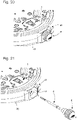
- control rod 4 At a rear end 6 which will be located outside the portable object once the latter has been fitted with a control device 1, the control rod 4 will receive an actuation ring 8 (see figure 20 ).
- control rod 4 At a front end 10 which will be located inside the control device 1 once the latter is assembled, the control rod 4 has a section 12, for example square, and successively receives a magnetic element 14 and a plain bearing 16.
- the magnetic assembly 14 comprises a magnetic ring 18 and a support ring 20 on which the magnetic ring 18 is typically fixed by gluing (see figure 4 ).
- the support ring 20 is a part of generally cylindrical shape. As seen on the figure 5 , the support ring 20 has, from back to front, a first section 22a of a first outer diameter D1 on which the magnetic ring 18 is engaged, and a second section 22b of a second outer diameter D2 greater than the first outer diameter D1 and which delimits a shoulder 24 against which the magnetic ring 18 bears.
- the first section 22a of the support ring 20 is pierced with a square hole 26 which is adapted in shape and size to the square section 12 of the control rod 4 and forms with this control rod 4 a system of the pinion type. flowing.
- the support ring 20 and the magnetic ring 18 remain stationary when the control rod 4 is slid axially.
- the control rod 4 drives the support ring 20 and the magnet 18 in rotation when this control rod 4 is rotated. It is understood from the above that the magnetic ring 18, carried by the support ring 20, is not in contact with the control rod 4, this which makes it possible to protect it in the event of shocks applied to the portable object equipped with a control device 1.
- the plain bearing 16 defines (see figure 5 ) a cylindrical housing 28 whose first inside diameter D3 is very slightly greater than the diameter of the circle in which the square section 12 of the control rod 4 fits in order to allow this control rod 4 to slide axially and/or to rotate inside this cylindrical housing 28.
- the plain bearing 16 thus guarantees perfect axial guidance of the control rod 4.
- the square hole 26 made in the first section 22a of the support ring 20 is extended towards the front of the control device 1 by an annular hole 30 whose second inside diameter D4 is adjusted to the third outside diameter D5 of the plain bearing 16.
- the support ring 20 is thus threaded freely in rotation on the plain bearing 16 and comes into axial abutment against this plain bearing 16, which guarantees the perfect axial alignment of these two parts and makes it possible to correct any problems of concentricity that a sliding pinion type coupling can pose.
- the plain bearing 16 is provided on its outer surface with a circular collar 32 which protrudes into a first groove 34a and into a second groove 34b formed respectively in the lower frame 2 (see figure 2 ) and in an upper frame 36 (see figure 6 ) arranged to cap the lower frame 2 and for example made of an injected plastic material or a non-magnetic metallic material.
- the magnetic assembly 14 and the plain bearing 16 described above are indicated for purely illustrative purposes only.
- the plain bearing 16 for example made of steel or brass, is provided to prevent the control rod 4, for example made of steel, from rubbing against the lower 2 and upper 36 frames and causing wear of the material. plastic in which these two lower 2 and upper 36 frames are typically made.
- the control rod 4 is directly carried by the lower frame 2.
- the magnetic ring 18 and the support ring 20 on which the magnetic ring 18 is fixed are provided for the case where the rotation of the control rod 4 is detected by a local variation of the magnetic field induced by the pivoting of the magnetic ring 18. It is however entirely possible to replace the magnetic assembly 14 for example by a sliding pinion which, depending on its position, will for example control the winding of a barrel spring or the setting at the time of a watch fitted with the control device 1.
- control rod 4 can have any type of section which deviates from a circular section, for example triangular or oval.
- the lower frame 2 and the upper frame 36, the meeting of which defines the external geometry of the control device 1, are for example of generally parallelepiped shape.
- the lower frame 2 forms a cradle which receives the control rod 4.
- the lower frame 2 comprises towards the front a first receiving surface 38 of semi-circular profile which serves as a seat for the plain bearing 16 and in which is provided the first groove 34a which receives the circular flange 32. The immobilization of the plain bearing 16 both axially and in rotation is thus ensured.
- the lower frame 2 further comprises towards the rear a second receiving surface 40 whose semi-circular profile is centered on the longitudinal axis of symmetry XX of the control rod 4, but whose diameter is greater than that of this control rod 4. It is important to clearly understand that the control rod 4 bears on the second receiving surface 40 only at the stage where the control device 1, assembled, is tested before being integrated into the portable object. At this stage of the assembly, the control rod 4 is introduced into the control device 1 for test purposes and extends horizontally in being supported and guided axially by the plain bearing 16 on the side of its front end 10 and by the second receiving surface 40 on the side of its rear end 6.
- control rod 4 passes through a hole 42 provided in a middle part 48 of the portable object in which it is guided and supported (see figure 21 ) and which is delimited at the bottom by a bottom 49.
- Third and fourth clearance surfaces 44a and 46a of semi-circular profile are also provided in the lower frame 2 and complementary clearance surfaces 44b and 46b (see figure 6 ) are provided in the upper frame 36 to receive the magnetic assembly 14 consisting of the magnetized ring 18 and its support ring 20. It will be noted that the magnetized ring 18 and its support ring 20 are not in contact with the third and fourth clearance surfaces 44a, 46a and the complementary clearance surfaces 44b and 46b when the control device 1 is assembled and mounted in the portable object. It is also noted that the third clearance surface 44a and its corresponding complementary clearance surface 44b are delimited by an annular flange 50 for the axial locking of the magnetic assembly 14.
- the control rod 4 has a cylindrical section 52 whose diameter is between the diameter of the circle in which the square section 12 of the control rod 4 fits and the pitch diameter of a rear section 54 of this same control rod 4 at the end of which is fixed the actuation crown 8.
- This cylindrical section 52 of reduced diameter forms a groove 56 in which is placed a plate 58 for indexing the position of the control rod 4 (see Figure 7A ).
- the position indexing plate 58 has a curved portion 60 which matches the profile of the cylindrical section 52 of reduced diameter.
- the position indexing plate 58 can be obtained, for example, by stamping a thin conductive metal sheet of electricity.
- this position indexing plate 58 for example by molding a hard plastic material filled with conductive particles.
- the engagement of the position indexing plate 58 in the groove 56 guarantees the coupling in translation from front to rear and from rear to front between the control rod 4 and the position indexing plate 58.
- the position indexing plate 58 is free with respect to the control rod 4 in a vertical direction z perpendicular to the longitudinal axis of symmetry XX of the control rod 4.
- the position indexing plate 58 is a substantially planar part of general U shape.
- This position indexing plate 58 comprises two substantially rectilinear guide arms 62 which extend parallel to each other and which are connected to the to each other by the curved portion 60. These two guide arms 62 are guided axially, for example against two studs 64 formed in the lower frame 2 (see in particular picture 2 ). Guided by its two guide arms 62, the position indexing plate 58 slides along a rim 68 formed in the upper frame 36 and whose perimeter corresponds to that of the position indexing plate 58 (see figure 6 ).
- the position indexing plate 58 also includes two fingers 66a, 66b which extend vertically downward on either side of the two guide arms 62.
- the indexing plate of position 58 has the particular function of ensuring the translational guidance of the control rod 4 from front to back and from back to front.
- the fingers 66a, 66b they make it possible in particular to prevent the position indexing plate 58 from bracing when the latter moves in translation.
- Two openings 70 having an approximately rectangular outline are formed in the guide arms 62 of the position indexing plate 58 (see in particular the figure 7B ). These two openings 70 extend symmetrically on either side of the longitudinal axis of symmetry XX of the control rod 4.
- the sides of the two openings 70 closest to the longitudinal axis of symmetry XX of the control rod 4 have a profile 72 of substantially sinusoidal shape formed of a first and a second hollow 74a and 74b separated by a peak 76.
- the two openings 70 made in the guide arms 62 are intended to receive the two ends 78 of a positioning spring 80 (see figure 8 ).
- This positioning spring 80 has a general U-shape with two arms 82 which extend in a horizontal plane and which are interconnected by a base 84. At their free end, the two arms 82 are extended by two rods 86 substantially rectilinear that rise vertically.
- the positioning spring 80 is intended to be mounted in the control device 1 from below the lower frame 2, so that the ends 78 of the rods 86 project into the openings 70 of the position indexing plate 58. It will be seen below that the cooperation between the position indexing plate 58 and the positioning spring 80 makes it possible to index the position of the control rod 4 between an unstable pushed position T0 and two stable positions T1 and T2.
- the position indexing plate 58 is coupled in translation with the control rod 4, but that it is free with respect to the control rod 4 in the vertical direction z. It is therefore necessary to take measures to prevent the position indexing plate 58 from disengaging from the control rod 4 under normal conditions of use, for example under the effect of gravity.
- a spring 88 for limiting the displacement of the position indexing plate 58 in the vertical direction z above and at a short distance from this position indexing plate 58.
- the displacement limiting spring 88 is imprisoned between the lower frame 2 and the upper frame 36 of the control device 1, but is not, under normal conditions of use, in contact with the position indexing plate 58, which makes it possible to prevent parasitic friction forces from being exerted on the control rod 4 which would make its difficult to handle and cause wear.
- the displacement limiting spring 88 is however sufficiently close to the position indexing plate 58 so that the latter cannot be uncoupled from the control rod 4 inadvertently.
- the displacement limiting spring 88 comprises a substantially rectilinear central part 90 from the ends of which extend two pairs of elastic arms 92 and 94. These elastic arms 92 and 94 extend on either side of the 90 of the displacement limiting spring 88, moving upwards from the horizontal plane in which this central part 90 extends. These elastic arms 92 and 94, being compressed when the upper frame 36 is joined to the lower frame 2, give the displacement limiting spring 88 its elasticity in the vertical direction z.
- pairs of elastic arms 92 and 94 are also provided a pair and, preferably, two pairs of rigid legs 96 which extend perpendicularly downwards on either side of the central part 90 of the displacement limiting spring 88
- These rigid lugs 96 which come to rest on the lower frame 2 when the upper frame 36 is placed on the lower frame 2, guarantee compliance with a minimum spacing between the position indexing plate 58 and the movement 88 under normal operating conditions of control device 1.
- the displacement limiting spring 88 guarantees the removable nature of the control device 1. Indeed, in the absence of the displacement limiting spring 88, the position indexing plate 58 should be integral with the control rod 4 and , as a result, the control rod 4 could no longer be removed. However, if the control stem 4 cannot be disassembled, the movement of the timepiece equipped with the control device 1 is also unremovable, which is not conceivable in particular in the case of an expensive timepiece.
- the control device 1 formed by the union of the lower 2 and upper 36 frames, is mounted in the portable object and when the control rod 4 is inserted into the control device 1 from outside the the portable object, the control rod 4 slightly lifts the position indexing plate 58 against the elastic force of the displacement limiting spring 88. Continuing to push the control rod 4 forward, there comes a when the position indexing plate 58 falls into the groove 56 under the effect of gravity. The control rod 4 and the position indexing plate 58 are then coupled in translation.
- a disengagement plate 98 is provided to allow dismantling of the control rod 4 (see figure 10 ).
- This disengagement plate 98 is generally H-shaped and comprises a straight segment 100 which extends parallel to the longitudinal axis of symmetry XX of the control rod 4 and to which are attached a first and a second cross section 102 and 104
- the first cross section 102 is further provided at its two free ends with two lugs 106 bent at a substantially right angle.
- the disengagement plate 98 is received in a housing 108 made in the lower frame 2 and located under the control rod 4. This housing 108 communicates with the outside of the control device 1 via a hole 110 which opens into a lower face 112 of the control device 1 (see figure 11 ).
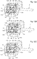
- the control rod 4 From its stable rest position T1, the control rod 4 can be pushed forwards into an unstable position T0 or pulled into a stable position T2. These three positions T0, T1 and T2 of the control rod 4 are indexed by cooperation between the position indexing plate 58 and the positioning spring 80. More precisely (see Figure 12A ), the stable rest position T1 corresponds to the position in which the ends 78 of the rods 86 of the positioning spring 80 protrude into the first recesses 74a of the two openings 70 formed in the guide arms 62 of the indexing plate of position 58. From this stable rest position T1, the control rod 4 can be pushed forward into an unstable position T0 (see figure 12B ).
- the ends 78 of the rods 86 engage on a second ramp profile 118 which extends the first ramp profile 114 with a second slope ⁇ lower than the first slope ⁇ of the first ramp profile 114.
- the effort that the user must provide to continue to advance the rod control rod 4 drops suddenly and the user feels a click which indicates to him the transition of the control rod 4 between its position T1 and its position T0.
- the rods 86 of the positioning spring 80 continue to deviate slightly from their rest position and tend to want to approach each other again under the effect of their force.
- First and second contact springs 120a and 120b are housed compressed in a first and a second cavity 122a and 122b made in the lower frame 2.
- These first and second contact springs 120a and 120b can be helical contact springs, leaf springs or others.
- the two cavities 122a, 122b preferably but not necessarily extend horizontally. Because the two contact springs 120a, 120b are installed in the compressed state, the precision of their positioning is conditioned by the tolerance with which the lower frame 2 is manufactured. However, the precision with which the lower frame 2 is manufactured is greater than the manufacturing precision of these first and second contact springs 120a, 120b. Consequently, the precision with which the position T0 of the control rod 4 is detected is high.
- one of the ends of the first and second contact springs 120a, 120b is curved so as to form two contact lugs 124 which will rest on two corresponding first contact pads 126 provided on the surface of a sheet of flexible printed circuit 128.
- the first and second contact springs 120a, 120b are of the same length. However, preferably, the first cavity 122a will for example be longer than the second cavity 122b in particular to take tolerance problems into account (the difference in length between the two cavities 122a, 122b is a few tenths of a millimeter). In this way, when the control rod 4 is pushed forward into its position T0, the finger 66a of the position indexing plate 58 which is in correspondence with the first contact spring 120a housed in the first cavity 122a the longest will come into contact with the latter and begin to compress it.
- the control rod 4 will continue to advance and the second finger 66b of the position indexing plate 58 will come into contact with the second contact spring 120b housed in the second shortest cavity 122b. At this time, the position indexing plate 58 will be in contact with the first and second contact springs 120a, 120b and the electric current will pass through the position indexing plate 58, which allows to detect the closing of the electrical contact between the first two contact springs 120a, 120b. Note that the fingers 66a, 66b of the position indexing plate 58 come into abutment contact with the first and second contact springs 120a, 120b. There is therefore no friction or wear when the control rod 4 is pushed forward into position T0 and it closes the circuit between the first and second contact springs 120a, 120b.
- the first contact spring 120a housed in the first longest cavity 122a is at the compressed state. Consequently, when the user releases the pressure on the control rod 4, this first contact spring 120a relaxes and forces the return of the control rod 4 from its unstable pushed position T0 to its first stable position T1.
- the first and second contact springs 120a, 120b therefore simultaneously play the role of electrical contact parts and elastic return means of the control rod 4 in its first stable position T1.
- third and fourth contact springs 130a and 130b can be either helical contact springs, leaf springs or others.
- the third and fourth cavities 132a, 132b preferentially extend vertically for reasons of size of the control device 1.
- the fingers 66a, 66b of the position indexing plate 58 also come into abutment contact with the third and fourth contact springs 130a, 130b, so that any risk frictional wear is avoided. Furthermore, the third and fourth contact springs 130a, 130b are able to flex when the fingers 66a, 66b of the position indexing plate 58 hit them, and therefore to absorb any lack of precision in the positioning of the position index plate 58.
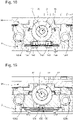
- the third and fourth contact springs 130a, 130b are arranged to work in bending (see figures 14A and 14B ). Indeed, with contact springs 130a, 130b whose diameter is constant, the fingers 66a, 66b of the position indexing plate 58 come into contact with the contact springs 130a, 130b along a large surface close to their points. anchorage in the lower frame 2 and the upper frame 36. The proximity of the contact surface with the anchoring points of the contact springs 130a, 130b induces in these contact springs 130a, 130b shear stresses which can lead premature wear and breakage of the latter.
- the contact springs 130a, 130b preferably present substantially at mid-height an increase in diameter 134 with which the fingers 66a, 66b of the position indexing plate 58 come into contact when the control rod 4 is pulled into its stable position T2.
- the third and fourth contact springs 130a, 130b are guided in two holes 136 formed in the upper frame 36 and come into contact with second contact pads 138 provided on the surface of the flexible printed circuit sheet 128 It will be understood that, when the control rod 4 is pulled back into its stable position T2, the fingers 66a, 66b of the plate position indexing 58 come into contact over a reduced area with the third and fourth contact springs 130a and 130b at their largest diameter 134, which allows these contact springs 130a, 130b to flex between their two points anchor in the lower frame 2 and the upper frame 36.
- the flexible printed circuit sheet 128 is fixed on a plate 140 located on the side of a dial of the portable object. It has in particular a cutout 142 adapted in shape and size to receive the upper frame 36. A portion 144 of the flexible printed circuit sheet 128 remains free (see figure 16 ). This free portion 144 of the flexible printed circuit sheet 128 carries a plurality of electronic components 146 as well as third contact pads 148 on which are fixed at least one and, in the example shown, two inductive sensors 150.
- the fixing of the inductive sensors 150 on the third contact pads 148 makes it possible, via the flexible printed circuit sheet 128, to connect these inductive sensors 150 in particular to a power source and to a microprocessor (not shown) housed in the portable object.
- the power source will supply the inductive sensors 150 with the electrical energy necessary for their operation, and the microprocessor will receive and process the signals supplied by the inductive sensors 150.
- the free portion 144 of the flexible printed circuit sheet 128 is connected to the remainder of the flexible printed circuit sheet 128 by two strips 152 which allow the free portion 144 to be folded around the assembly of the upper frame 36 and the lower frame 2 , then to fold the free portion 144 against the lower face 112 of the lower frame 2, so that the inductive sensors 150 penetrate into two housings 156 made in the lower face 112 of the lower frame 2.
- the sensors inductive 150 lie precisely located under the magnetic ring 18, which guarantees reliable detection of the direction of rotation of the control rod 4.
- the assembly is covered by a retaining plate 158 provided with at least one elastic finger 160 (two in the example shown) which exerts on the inductive sensors 150 an elastic pressure force directed vertically upwards so as to flatten these inductive sensors 150 at the bottom of their housings 156 (see figure 17B ).
- the resilient fingers 160 press against the flexible printed circuit sheet 128 preferably where the inductive sensors 150 are attached.
- the retaining plate 158 is fixed to the lower frame 2 for example by means of two screws 162.
- the control rod 4 is carried by the lower frame 2 which serves as its cradle.
- the two inductive sensors 150 are arranged in the two housings 156 formed in this same lower frame 2 and are pressed against the bottom of these housings 156 by one or two elastic fingers 160 (see figure 18 ). Consequently, the precision of the relative positioning of the inductive sensors 150 and the magnetic ring 18 which is mounted fixed relative to the control rod 4 is determined solely by the precision with which the lower frame 2 is produced. such as brass, is sufficient to guarantee the correct positioning of the inductive sensors 150 and of the magnetic ring 18 even in the case of mass production.
- the inductive sensors 150 are elastically forced against the bottom of the housings 156 by the elastic finger(s) 160, this makes it possible to compensate for any play due to manufacturing tolerances.
- These manufacturing tolerances can in particular come from the step of welding the inductive components 150 onto the flexible printed circuit sheet 128. This welding operation is carried out for example in an oven by means of a solder paste deposited on the pads contact 148 of the flexible printed circuit sheet 128.
- the inductive sensor(s) 150 are preferably oriented so that their sensitive element detects a fluctuation of the magnetic induction in the vertical direction z only. In other words, the inductive sensors are totally insensitive to the horizontal components along the orthogonal axes x and y of the magnetic induction.
- the amplitude of the rotation and the position of the control rod 4 can be determined with only average precision. Indeed, when the magnetic ring 18 rotates under the effect of the actuation of the control rod 4, the inductive sensor 150 produces a sinusoidal signal whose amplitude of the variation fluctuates according to the value of the angle considered. If one is for example in a zone close to the value ⁇ /2, the sinusoidal signal varies slightly, so that the amount of movement of the control rod 4 and the position thereof can only be determined with medium precision. On the other hand, if one is in a zone close to the value ⁇ , the sinusoidal signal fluctuates strongly, so that the the amount by which the control rod 4 is turned and the position of the latter can be determined with good precision.
- the system described above is quite suitable.
- the two inductive sensors 150 are arranged at equal distance on either side of a vertical plane P of longitudinal symmetry of the control rod 4.
- the two inductive sensors 150 are arranged with respect to the rod control 4 so that, when the magnetized ring 18 rotates under the effect of the actuation of the control rod 4, the two inductive sensors 150 produce sinusoidal signals sin(x) and sin(x+ ⁇ ) which are out of phase with respect to each other by an angle ⁇ of between 60° and 120°, and preferably substantially equal to 90°.
- ⁇ of between 60° and 120°, and preferably substantially equal to 90°.
- the inductive sensors 150 were preferably oriented so that their sensitive element only detects the fluctuations of the magnetic induction along the vertical axis z.
- This component of the magnetic induction is the sum of the inductions along the z axis generated by the magnetic ring 18 and by the magnetic field external to the portable object.
- the inductive sensors 150 being very close to each other, the influence exerted on them by the external magnetic field is substantially the same for the two inductive sensors 150. Consequently, by making the ratio between the two sinusoidal signals sin(x) and sin(x+ ⁇ ), the component of the magnetic induction due to the magnetic field external to the portable object is eliminated.
- the response of the system formed by the control rod 4, the magnetic ring 18 and the inductive sensors 150 is therefore completely independent of the external magnetic field, and it is not necessary to take measures to magnetically shield the portable object. Also, the system response is independent of temperature since temperature has the same effect on both inductive sensors.
- the present invention is not limited to the embodiment which has just been described and that various simple modifications and variants can be envisaged by those skilled in the art without departing from the scope of the invention as defined. by the appended claims.
- the dimensions of the magnetized ring can be extended so as to make it correspond to a hollow cylinder.
Landscapes
- Physics & Mathematics (AREA)
- General Physics & Mathematics (AREA)
- Electric Clocks (AREA)
- Measurement Of Length, Angles, Or The Like Using Electric Or Magnetic Means (AREA)
- Transmission And Conversion Of Sensor Element Output (AREA)
- Reciprocating, Oscillating Or Vibrating Motors (AREA)
Claims (9)
- Tragbarer Gegenstand, der ein Gestell(2) umfasst, das so eingerichtet ist, dass es als Bett für eine Steuerwelle (4) dient, deren drehende Betätigung es ermöglicht, mindestens eine elektronische oder mechanische Funktion des tragbaren Gegenstandes zu steuern, wobei ein magnetisierter Ring (18) von der Steuerwelle (4) drehend angetrieben wird, wobei die Drehung des magnetisierten Ringes (18) von mindestens einem induktiven Sensor (150), der an einer Fläche (168) des Gestells (2) in Anlage gehalten wird, erfasst wird, dadurch gekennzeichnet, dass der induktive Sensor (150) in einer Lagerung (156) des Gestell (2) angeordnet ist, in dessen Innerem der induktive Sensor (150) von elastischen Mitteln oder durch Verklebung gehalten wird.
- Tragbarer Gegenstand nach Anspruch 1, dadurch gekennzeichnet, dass er eine Halteplatte (158) umfasst, die mit mindestens einem elastischen Finger (160) versehen ist, der durch Druck auf den induktiven Sensor (150) diesen induktiven Sensor (150) im Inneren der Lagerung (156), in der er angeordnet ist, hält.
- Tragbarer Gegenstand nach Anspruch 2, dadurch gekennzeichnet, dass der induktive Sensor (150) an einer Leiterfolie (128) befestigt ist, und der elastische Finger (160) an der Stelle, an der der induktive Sensor (150) befestigt ist, auf die Leiterfolie (128) drückt.
- Tragbarer Gegenstand nach Anspruch 3, dadurch gekennzeichnet, dass die Leiterfolie (128) flexibel ist, und dadurch, dass sie am Gestell (2) so abgekantet ist, dass der induktive Sensor (150) in der Lagerung (156) angeordnet ist.
- Tragbarer Gegenstand nach einem der Ansprüche 2 bis 4, dadurch gekennzeichnet, dass der elastische Finger (160) die Fixierung des induktiven Sensors (150) in einer vertikalen Richtung (z) gewährleistet.
- Tragbarer Gegenstand nach Anspruch 5, dadurch gekennzeichnet, dass der elastische Finger (160) so eingerichtet ist, dass er den induktiven Sensor (150) an einen Boden der Lagerung (156), in der er angeordnet ist, presst.
- Tragbarer Gegenstand nach einem der Ansprüche 5 oder 6, dadurch gekennzeichnet, dass der induktive Sensor (150) ein für die Schwankungen der magnetischen Induktion empfindliches Element umfasst, das so ausgerichtet ist, dass das empfindliche Element eine Schwankung der magnetischen Induktion nur in der vertikalen Richtung (z) erfasst.
- Tragbarer Gegenstand nach einem der Ansprüche 1 bis 7, dadurch gekennzeichnet, dass er zwei induktive Sensoren (150) umfasst, die in zwei Lagerungen (156) des Gestell (2) untergebracht sind und die beidseits einer vertikalen Längssymmetrieebene (P) der Steuerwelle (4) in gleichem Abstand angeordnet sind.
- Tragbarer Gegenstand nach Anspruch 8, dadurch gekennzeichnet, dass die zwei induktiven Sensoren (150) in Bezug auf die Steuerwelle (4) so eingerichtet sind, dass, wenn der magnetisierte Ring (18) unter Wirkung der Betätigung der Steuerwelle (4) dreht, die zwei induktiven Sensoren (150) Signale erzeugen, die in Bezug zueinander um einen Winkel δ im Bereich zwischen 60° und 120° phasenverschoben sind.
Applications Claiming Priority (1)
| Application Number | Priority Date | Filing Date | Title |
|---|---|---|---|
| EP16202476.4A EP3333645A1 (de) | 2016-12-06 | 2016-12-06 | Tragbarer gegenstand, der einen drehbaren steuerstab umfasst, dessen betätigung durch die messung einer magnetischen induktion erfasst wird |
Publications (2)
| Publication Number | Publication Date |
|---|---|
| EP3333647A1 EP3333647A1 (de) | 2018-06-13 |
| EP3333647B1 true EP3333647B1 (de) | 2022-12-07 |
Family
ID=57539043
Family Applications (2)
| Application Number | Title | Priority Date | Filing Date |
|---|---|---|---|
| EP16202476.4A Withdrawn EP3333645A1 (de) | 2016-12-06 | 2016-12-06 | Tragbarer gegenstand, der einen drehbaren steuerstab umfasst, dessen betätigung durch die messung einer magnetischen induktion erfasst wird |
| EP17196387.9A Active EP3333647B1 (de) | 2016-12-06 | 2017-10-13 | Tragbarer gegenstand, der einen drehbaren steuerstab umfasst, dessen betätigung durch die messung einer magnetischen induktion erfasst wird |
Family Applications Before (1)
| Application Number | Title | Priority Date | Filing Date |
|---|---|---|---|
| EP16202476.4A Withdrawn EP3333645A1 (de) | 2016-12-06 | 2016-12-06 | Tragbarer gegenstand, der einen drehbaren steuerstab umfasst, dessen betätigung durch die messung einer magnetischen induktion erfasst wird |
Country Status (7)
| Country | Link |
|---|---|
| US (1) | US10261476B2 (de) |
| EP (2) | EP3333645A1 (de) |
| JP (1) | JP6557313B2 (de) |
| KR (1) | KR102045632B1 (de) |
| CN (1) | CN108153139B (de) |
| FI (1) | FI3333647T3 (de) |
| TW (1) | TWI739934B (de) |
Families Citing this family (4)
| Publication number | Priority date | Publication date | Assignee | Title |
|---|---|---|---|---|
| EP3333646A1 (de) * | 2016-12-06 | 2018-06-13 | ETA SA Manufacture Horlogère Suisse | Tragbarer gegenstand, der einen drehbaren steuerstab umfasst, dessen betätigung durch zwei induktionssensoren erkannt wird |
| EP3671134B1 (de) | 2018-12-21 | 2022-09-21 | The Swatch Group Research and Development Ltd | System und verfahren zur bestimmung mindestens eines parameters der winkelbewegung einer achse |
| CN209355950U (zh) * | 2019-01-04 | 2019-09-06 | 安徽华米信息科技有限公司 | 转动检测模块及包含其的电子设备 |
| EP3835885B1 (de) | 2019-12-10 | 2023-12-06 | The Swatch Group Research and Development Ltd | Armbanduhr mit steuerungsorgan |
Family Cites Families (20)
| Publication number | Priority date | Publication date | Assignee | Title |
|---|---|---|---|---|
| JPS5194870A (de) * | 1975-02-18 | 1976-08-19 | ||
| JPH058491U (ja) * | 1991-07-19 | 1993-02-05 | カシオ計算機株式会社 | センサを備えた小型電子機器 |
| FR2759792B1 (fr) | 1997-02-17 | 1999-04-16 | Centre Electron Horloger | Piece d'horlogerie comportant un dispositif de detection sans contact |
| CH691132A5 (fr) * | 1997-02-19 | 2001-04-30 | Italo Cherubini | Dispositif de trasmission pour la manoeuvre d'un store. |
| FR2763710B1 (fr) * | 1997-05-26 | 1999-08-27 | Jdc Electronic Sa | Dispositif de commande de fonctions d'un instrument horaire et procede pour la mise en oeuvre de ce dispositif |
| JP2005017012A (ja) * | 2003-06-24 | 2005-01-20 | Seiko Epson Corp | 電子機器および時計 |
| CA2513849A1 (en) * | 2004-07-29 | 2006-01-29 | Dwyer Instruments, Inc. | Gauge having a magnetically driven pointer rotation device |
| ATE496319T1 (de) * | 2006-11-09 | 2011-02-15 | Swatch Group Res & Dev Ltd | Magnetische vorrichtung zur betätigung einer uhr |
| HK1095988A2 (en) * | 2007-01-31 | 2007-05-18 | National Electronics & Watch Co. Ltd. | A timepiece apparatus |
| EP2072008A3 (de) * | 2007-12-19 | 2013-04-17 | Beppo Hilfiker | Vorrichtung zur Bedienung eines elektronischen Multifunktionsgerätes |
| JP2009218134A (ja) * | 2008-03-12 | 2009-09-24 | Panasonic Corp | 回転操作型入力装置 |
| JP4849348B2 (ja) * | 2008-12-09 | 2012-01-11 | カシオ計算機株式会社 | 回転スイッチ |
| JP4962803B2 (ja) * | 2009-06-09 | 2012-06-27 | カシオ計算機株式会社 | 回転スイッチ |
| EP2787399B1 (de) * | 2011-12-13 | 2015-07-29 | ETA SA Manufacture Horlogère Suisse | Mechanisches Uhrwerk einer modularen Uhr mit funktionellen Modulen |
| US10081678B2 (en) * | 2013-02-04 | 2018-09-25 | Emory University | Specific binding antibodies of glycoprotein IB alpha as selective ectodomain shedding inhibitors |
| EP4513293A3 (de) * | 2013-06-11 | 2025-06-04 | Apple Inc. | Elektronische uhr mit drehbarem eingabemechanismus |
| US9753436B2 (en) * | 2013-06-11 | 2017-09-05 | Apple Inc. | Rotary input mechanism for an electronic device |
| CN110262677B (zh) * | 2013-09-03 | 2022-08-09 | 苹果公司 | 计算机实现的方法、电子设备和计算机可读存储介质 |
| US10599101B2 (en) * | 2014-09-02 | 2020-03-24 | Apple Inc. | Wearable electronic device |
| CN105389074A (zh) * | 2015-07-28 | 2016-03-09 | 广东欧珀移动通信有限公司 | 一种智能手表的控制方法及智能手表 |
-
2016
- 2016-12-06 EP EP16202476.4A patent/EP3333645A1/de not_active Withdrawn
-
2017
- 2017-10-13 EP EP17196387.9A patent/EP3333647B1/de active Active
- 2017-10-13 FI FIEP17196387.9T patent/FI3333647T3/fi active
- 2017-10-23 TW TW106136309A patent/TWI739934B/zh active
- 2017-10-24 US US15/791,510 patent/US10261476B2/en active Active
- 2017-11-13 JP JP2017217957A patent/JP6557313B2/ja active Active
- 2017-12-01 KR KR1020170164004A patent/KR102045632B1/ko active Active
- 2017-12-05 CN CN201711267651.7A patent/CN108153139B/zh active Active
Also Published As
| Publication number | Publication date |
|---|---|
| JP2018091835A (ja) | 2018-06-14 |
| CN108153139B (zh) | 2021-09-07 |
| CN108153139A (zh) | 2018-06-12 |
| JP6557313B2 (ja) | 2019-08-07 |
| KR102045632B1 (ko) | 2019-11-15 |
| HK1255962A1 (zh) | 2019-09-06 |
| EP3333645A1 (de) | 2018-06-13 |
| FI3333647T3 (fi) | 2023-03-18 |
| EP3333647A1 (de) | 2018-06-13 |
| KR20180064982A (ko) | 2018-06-15 |
| TW201821824A (zh) | 2018-06-16 |
| TWI739934B (zh) | 2021-09-21 |
| US10261476B2 (en) | 2019-04-16 |
| US20180157218A1 (en) | 2018-06-07 |
Similar Documents
| Publication | Publication Date | Title |
|---|---|---|
| EP3475768B1 (de) | Tragbarer gegenstand, der einen drehbaren steuerstab umfasst, dessen betätigung durch zwei induktionssensoren erkannt wird | |
| EP3333647A1 (de) | Tragbarer gegenstand, der einen drehbaren steuerstab umfasst, dessen betätigung durch die messung einer magnetischen induktion erfasst wird | |
| FR2724723A1 (fr) | Capteur incremental de vitesse et/ou de position. | |
| EP3418814B1 (de) | Bedienungsvorrichtung mit drücker-krone für ein kleines tragbares objekt | |
| EP3382470A1 (de) | Oszillator einer uhr mit flexiblem zapfen | |
| EP2980658B1 (de) | Vorrichtung zum Zusammenbau und Regulieren einer Spirale | |
| EP3333648B1 (de) | Vorrichtung zur steuerung von mindestens zwei elektronischen und/oder mechanischen funktionen eines tragbaren gegenstands | |
| EP3835887B1 (de) | Armbanduhr mit steuerungsorgan | |
| CH712573B1 (fr) | Objet portable comprenant une tige de commande rotative dont l'actionnement est détecté par mesure d'une induction magnétique. | |
| CH712575B1 (fr) | Objet portable comprenant une tige de commande rotative dont l'actionnement est détecté au moyen de deux capteurs inductifs. | |
| WO2003042706A1 (fr) | Dispositif de securisation du deplacement d'un organe mobile | |
| CH712574B1 (fr) | Dispositif pour la commande d'au moins deux fonctions électroniques et/ou mécaniques d'un objet portable. | |
| CH713321B1 (fr) | Dispositif de commande à couronne-poussoir pour un objet portable de petites dimensions. | |
| WO2011157404A1 (fr) | Procede de montage d'un detecteur de deplacement angulaire et dispositif de detection equipe de moyens de montage correspondants | |
| EP1960848B1 (de) | Hammer einer uhr | |
| CH634407A5 (fr) | Instrument de mesure de cotes. | |
| EP2192604A1 (de) | Dateneingabevorrichtung mit verbesserter Anschlagcharakteristik | |
| FR2633544A1 (fr) | Cle dynamometrique a detection electrique | |
| CH712612A1 (fr) | Organe indicateur comportant au moins un élément mobile, système d'affichage associé et pièce d'horlogerie comportant un tel système d'affichage. | |
| FR2733708A1 (fr) | Dispositif de clavetage d'une coupelle d'appui d'un ressort de soupape sur une tige de soupape | |
| HK1255962B (en) | Portable object comprising a rotating control stem | |
| FR2751076A1 (fr) | Thermometre minima-maxima a aiguilles | |
| EP3460587A1 (de) | Führungssystem | |
| WO2012085404A1 (fr) | Instrument de mesure de la position d'un volet d'un avion | |
| CH708722B1 (fr) | Mouvement horloger comportant un levier de commande destiné à être actionné par un poussoir. |
Legal Events
| Date | Code | Title | Description |
|---|---|---|---|
| PUAI | Public reference made under article 153(3) epc to a published international application that has entered the european phase |
Free format text: ORIGINAL CODE: 0009012 |
|
| STAA | Information on the status of an ep patent application or granted ep patent |
Free format text: STATUS: THE APPLICATION HAS BEEN PUBLISHED |
|
| AK | Designated contracting states |
Kind code of ref document: A1 Designated state(s): AL AT BE BG CH CY CZ DE DK EE ES FI FR GB GR HR HU IE IS IT LI LT LU LV MC MK MT NL NO PL PT RO RS SE SI SK SM TR |
|
| AX | Request for extension of the european patent |
Extension state: BA ME |
|
| STAA | Information on the status of an ep patent application or granted ep patent |
Free format text: STATUS: REQUEST FOR EXAMINATION WAS MADE |
|
| 17P | Request for examination filed |
Effective date: 20181213 |
|
| RBV | Designated contracting states (corrected) |
Designated state(s): AL AT BE BG CH CY CZ DE DK EE ES FI FR GB GR HR HU IE IS IT LI LT LU LV MC MK MT NL NO PL PT RO RS SE SI SK SM TR |
|
| STAA | Information on the status of an ep patent application or granted ep patent |
Free format text: STATUS: EXAMINATION IS IN PROGRESS |
|
| 17Q | First examination report despatched |
Effective date: 20190227 |
|
| GRAP | Despatch of communication of intention to grant a patent |
Free format text: ORIGINAL CODE: EPIDOSNIGR1 |
|
| STAA | Information on the status of an ep patent application or granted ep patent |
Free format text: STATUS: GRANT OF PATENT IS INTENDED |
|
| INTG | Intention to grant announced |
Effective date: 20220929 |
|
| GRAS | Grant fee paid |
Free format text: ORIGINAL CODE: EPIDOSNIGR3 |
|
| GRAA | (expected) grant |
Free format text: ORIGINAL CODE: 0009210 |
|
| STAA | Information on the status of an ep patent application or granted ep patent |
Free format text: STATUS: THE PATENT HAS BEEN GRANTED |
|
| AK | Designated contracting states |
Kind code of ref document: B1 Designated state(s): AL AT BE BG CH CY CZ DE DK EE ES FI FR GB GR HR HU IE IS IT LI LT LU LV MC MK MT NL NO PL PT RO RS SE SI SK SM TR |
|
| REG | Reference to a national code |
Ref country code: GB Ref legal event code: FG4D Free format text: NOT ENGLISH |
|
| REG | Reference to a national code |
Ref country code: CH Ref legal event code: EP Ref country code: AT Ref legal event code: REF Ref document number: 1536652 Country of ref document: AT Kind code of ref document: T Effective date: 20221215 |
|
| REG | Reference to a national code |
Ref country code: DE Ref legal event code: R096 Ref document number: 602017064329 Country of ref document: DE |
|
| REG | Reference to a national code |
Ref country code: IE Ref legal event code: FG4D Free format text: LANGUAGE OF EP DOCUMENT: FRENCH |
|
| REG | Reference to a national code |
Ref country code: LT Ref legal event code: MG9D |
|
| REG | Reference to a national code |
Ref country code: NL Ref legal event code: MP Effective date: 20221207 |
|
| PG25 | Lapsed in a contracting state [announced via postgrant information from national office to epo] |
Ref country code: SE Free format text: LAPSE BECAUSE OF FAILURE TO SUBMIT A TRANSLATION OF THE DESCRIPTION OR TO PAY THE FEE WITHIN THE PRESCRIBED TIME-LIMIT Effective date: 20221207 Ref country code: NO Free format text: LAPSE BECAUSE OF FAILURE TO SUBMIT A TRANSLATION OF THE DESCRIPTION OR TO PAY THE FEE WITHIN THE PRESCRIBED TIME-LIMIT Effective date: 20230307 Ref country code: LT Free format text: LAPSE BECAUSE OF FAILURE TO SUBMIT A TRANSLATION OF THE DESCRIPTION OR TO PAY THE FEE WITHIN THE PRESCRIBED TIME-LIMIT Effective date: 20221207 Ref country code: ES Free format text: LAPSE BECAUSE OF FAILURE TO SUBMIT A TRANSLATION OF THE DESCRIPTION OR TO PAY THE FEE WITHIN THE PRESCRIBED TIME-LIMIT Effective date: 20221207 |
|
| REG | Reference to a national code |
Ref country code: AT Ref legal event code: MK05 Ref document number: 1536652 Country of ref document: AT Kind code of ref document: T Effective date: 20221207 |
|
| PG25 | Lapsed in a contracting state [announced via postgrant information from national office to epo] |
Ref country code: RS Free format text: LAPSE BECAUSE OF FAILURE TO SUBMIT A TRANSLATION OF THE DESCRIPTION OR TO PAY THE FEE WITHIN THE PRESCRIBED TIME-LIMIT Effective date: 20221207 Ref country code: PL Free format text: LAPSE BECAUSE OF FAILURE TO SUBMIT A TRANSLATION OF THE DESCRIPTION OR TO PAY THE FEE WITHIN THE PRESCRIBED TIME-LIMIT Effective date: 20221207 Ref country code: LV Free format text: LAPSE BECAUSE OF FAILURE TO SUBMIT A TRANSLATION OF THE DESCRIPTION OR TO PAY THE FEE WITHIN THE PRESCRIBED TIME-LIMIT Effective date: 20221207 Ref country code: HR Free format text: LAPSE BECAUSE OF FAILURE TO SUBMIT A TRANSLATION OF THE DESCRIPTION OR TO PAY THE FEE WITHIN THE PRESCRIBED TIME-LIMIT Effective date: 20221207 Ref country code: GR Free format text: LAPSE BECAUSE OF FAILURE TO SUBMIT A TRANSLATION OF THE DESCRIPTION OR TO PAY THE FEE WITHIN THE PRESCRIBED TIME-LIMIT Effective date: 20230308 |
|
| PG25 | Lapsed in a contracting state [announced via postgrant information from national office to epo] |
Ref country code: NL Free format text: LAPSE BECAUSE OF FAILURE TO SUBMIT A TRANSLATION OF THE DESCRIPTION OR TO PAY THE FEE WITHIN THE PRESCRIBED TIME-LIMIT Effective date: 20221207 |
|
| PG25 | Lapsed in a contracting state [announced via postgrant information from national office to epo] |
Ref country code: SM Free format text: LAPSE BECAUSE OF FAILURE TO SUBMIT A TRANSLATION OF THE DESCRIPTION OR TO PAY THE FEE WITHIN THE PRESCRIBED TIME-LIMIT Effective date: 20221207 Ref country code: RO Free format text: LAPSE BECAUSE OF FAILURE TO SUBMIT A TRANSLATION OF THE DESCRIPTION OR TO PAY THE FEE WITHIN THE PRESCRIBED TIME-LIMIT Effective date: 20221207 Ref country code: PT Free format text: LAPSE BECAUSE OF FAILURE TO SUBMIT A TRANSLATION OF THE DESCRIPTION OR TO PAY THE FEE WITHIN THE PRESCRIBED TIME-LIMIT Effective date: 20230410 Ref country code: EE Free format text: LAPSE BECAUSE OF FAILURE TO SUBMIT A TRANSLATION OF THE DESCRIPTION OR TO PAY THE FEE WITHIN THE PRESCRIBED TIME-LIMIT Effective date: 20221207 Ref country code: CZ Free format text: LAPSE BECAUSE OF FAILURE TO SUBMIT A TRANSLATION OF THE DESCRIPTION OR TO PAY THE FEE WITHIN THE PRESCRIBED TIME-LIMIT Effective date: 20221207 Ref country code: AT Free format text: LAPSE BECAUSE OF FAILURE TO SUBMIT A TRANSLATION OF THE DESCRIPTION OR TO PAY THE FEE WITHIN THE PRESCRIBED TIME-LIMIT Effective date: 20221207 |
|
| P01 | Opt-out of the competence of the unified patent court (upc) registered |
Effective date: 20230701 |
|
| PG25 | Lapsed in a contracting state [announced via postgrant information from national office to epo] |
Ref country code: SK Free format text: LAPSE BECAUSE OF FAILURE TO SUBMIT A TRANSLATION OF THE DESCRIPTION OR TO PAY THE FEE WITHIN THE PRESCRIBED TIME-LIMIT Effective date: 20221207 Ref country code: IS Free format text: LAPSE BECAUSE OF FAILURE TO SUBMIT A TRANSLATION OF THE DESCRIPTION OR TO PAY THE FEE WITHIN THE PRESCRIBED TIME-LIMIT Effective date: 20230407 Ref country code: AL Free format text: LAPSE BECAUSE OF FAILURE TO SUBMIT A TRANSLATION OF THE DESCRIPTION OR TO PAY THE FEE WITHIN THE PRESCRIBED TIME-LIMIT Effective date: 20221207 |
|
| REG | Reference to a national code |
Ref country code: DE Ref legal event code: R097 Ref document number: 602017064329 Country of ref document: DE |
|
| PLBE | No opposition filed within time limit |
Free format text: ORIGINAL CODE: 0009261 |
|
| STAA | Information on the status of an ep patent application or granted ep patent |
Free format text: STATUS: NO OPPOSITION FILED WITHIN TIME LIMIT |
|
| PG25 | Lapsed in a contracting state [announced via postgrant information from national office to epo] |
Ref country code: DK Free format text: LAPSE BECAUSE OF FAILURE TO SUBMIT A TRANSLATION OF THE DESCRIPTION OR TO PAY THE FEE WITHIN THE PRESCRIBED TIME-LIMIT Effective date: 20221207 |
|
| 26N | No opposition filed |
Effective date: 20230908 |
|
| PG25 | Lapsed in a contracting state [announced via postgrant information from national office to epo] |
Ref country code: SI Free format text: LAPSE BECAUSE OF FAILURE TO SUBMIT A TRANSLATION OF THE DESCRIPTION OR TO PAY THE FEE WITHIN THE PRESCRIBED TIME-LIMIT Effective date: 20221207 |
|
| PG25 | Lapsed in a contracting state [announced via postgrant information from national office to epo] |
Ref country code: IT Free format text: LAPSE BECAUSE OF FAILURE TO SUBMIT A TRANSLATION OF THE DESCRIPTION OR TO PAY THE FEE WITHIN THE PRESCRIBED TIME-LIMIT Effective date: 20221207 Ref country code: MC Free format text: LAPSE BECAUSE OF FAILURE TO SUBMIT A TRANSLATION OF THE DESCRIPTION OR TO PAY THE FEE WITHIN THE PRESCRIBED TIME-LIMIT Effective date: 20221207 |
|
| REG | Reference to a national code |
Ref country code: BE Ref legal event code: MM Effective date: 20231031 |
|
| PG25 | Lapsed in a contracting state [announced via postgrant information from national office to epo] |
Ref country code: LU Free format text: LAPSE BECAUSE OF NON-PAYMENT OF DUE FEES Effective date: 20231013 |
|
| PG25 | Lapsed in a contracting state [announced via postgrant information from national office to epo] |
Ref country code: LU Free format text: LAPSE BECAUSE OF NON-PAYMENT OF DUE FEES Effective date: 20231013 |
|
| PG25 | Lapsed in a contracting state [announced via postgrant information from national office to epo] |
Ref country code: BE Free format text: LAPSE BECAUSE OF NON-PAYMENT OF DUE FEES Effective date: 20231031 |
|
| PG25 | Lapsed in a contracting state [announced via postgrant information from national office to epo] |
Ref country code: IE Free format text: LAPSE BECAUSE OF NON-PAYMENT OF DUE FEES Effective date: 20231013 |
|
| PG25 | Lapsed in a contracting state [announced via postgrant information from national office to epo] |
Ref country code: IE Free format text: LAPSE BECAUSE OF NON-PAYMENT OF DUE FEES Effective date: 20231013 |
|
| PG25 | Lapsed in a contracting state [announced via postgrant information from national office to epo] |
Ref country code: BG Free format text: LAPSE BECAUSE OF FAILURE TO SUBMIT A TRANSLATION OF THE DESCRIPTION OR TO PAY THE FEE WITHIN THE PRESCRIBED TIME-LIMIT Effective date: 20221207 |
|
| PG25 | Lapsed in a contracting state [announced via postgrant information from national office to epo] |
Ref country code: BG Free format text: LAPSE BECAUSE OF FAILURE TO SUBMIT A TRANSLATION OF THE DESCRIPTION OR TO PAY THE FEE WITHIN THE PRESCRIBED TIME-LIMIT Effective date: 20221207 |
|
| PG25 | Lapsed in a contracting state [announced via postgrant information from national office to epo] |
Ref country code: CY Free format text: LAPSE BECAUSE OF FAILURE TO SUBMIT A TRANSLATION OF THE DESCRIPTION OR TO PAY THE FEE WITHIN THE PRESCRIBED TIME-LIMIT; INVALID AB INITIO Effective date: 20171013 |
|
| PG25 | Lapsed in a contracting state [announced via postgrant information from national office to epo] |
Ref country code: HU Free format text: LAPSE BECAUSE OF FAILURE TO SUBMIT A TRANSLATION OF THE DESCRIPTION OR TO PAY THE FEE WITHIN THE PRESCRIBED TIME-LIMIT; INVALID AB INITIO Effective date: 20171013 |
|
| PGFP | Annual fee paid to national office [announced via postgrant information from national office to epo] |
Ref country code: FI Payment date: 20250923 Year of fee payment: 9 |
|
| PGFP | Annual fee paid to national office [announced via postgrant information from national office to epo] |
Ref country code: GB Payment date: 20250923 Year of fee payment: 9 |
|
| PGFP | Annual fee paid to national office [announced via postgrant information from national office to epo] |
Ref country code: FR Payment date: 20250924 Year of fee payment: 9 |
|
| REG | Reference to a national code |
Ref country code: CH Ref legal event code: U11 Free format text: ST27 STATUS EVENT CODE: U-0-0-U10-U11 (AS PROVIDED BY THE NATIONAL OFFICE) Effective date: 20251101 |
|
| PG25 | Lapsed in a contracting state [announced via postgrant information from national office to epo] |
Ref country code: TR Free format text: LAPSE BECAUSE OF FAILURE TO SUBMIT A TRANSLATION OF THE DESCRIPTION OR TO PAY THE FEE WITHIN THE PRESCRIBED TIME-LIMIT Effective date: 20221207 |
|
| PGFP | Annual fee paid to national office [announced via postgrant information from national office to epo] |
Ref country code: DE Payment date: 20250923 Year of fee payment: 9 |
|
| PGFP | Annual fee paid to national office [announced via postgrant information from national office to epo] |
Ref country code: CH Payment date: 20251101 Year of fee payment: 9 |