EP3333560B1 - Verfahren und system zur leckprüfung - Google Patents
Verfahren und system zur leckprüfung Download PDFInfo
- Publication number
- EP3333560B1 EP3333560B1 EP17199909.7A EP17199909A EP3333560B1 EP 3333560 B1 EP3333560 B1 EP 3333560B1 EP 17199909 A EP17199909 A EP 17199909A EP 3333560 B1 EP3333560 B1 EP 3333560B1
- Authority
- EP
- European Patent Office
- Prior art keywords
- gas
- bag
- flexible
- leak
- fluid flow
- Prior art date
- Legal status (The legal status is an assumption and is not a legal conclusion. Google has not performed a legal analysis and makes no representation as to the accuracy of the status listed.)
- Active
Links
Images



Classifications
-
- G—PHYSICS
- G01—MEASURING; TESTING
- G01M—TESTING STATIC OR DYNAMIC BALANCE OF MACHINES OR STRUCTURES; TESTING OF STRUCTURES OR APPARATUS, NOT OTHERWISE PROVIDED FOR
- G01M3/00—Investigating fluid-tightness of structures
- G01M3/02—Investigating fluid-tightness of structures by using fluid or vacuum
- G01M3/26—Investigating fluid-tightness of structures by using fluid or vacuum by measuring rate of loss or gain of fluid, e.g. by pressure-responsive devices, by flow detectors
- G01M3/32—Investigating fluid-tightness of structures by using fluid or vacuum by measuring rate of loss or gain of fluid, e.g. by pressure-responsive devices, by flow detectors for containers, e.g. radiators
- G01M3/3218—Investigating fluid-tightness of structures by using fluid or vacuum by measuring rate of loss or gain of fluid, e.g. by pressure-responsive devices, by flow detectors for containers, e.g. radiators for flexible or elastic containers
-
- G—PHYSICS
- G01—MEASURING; TESTING
- G01M—TESTING STATIC OR DYNAMIC BALANCE OF MACHINES OR STRUCTURES; TESTING OF STRUCTURES OR APPARATUS, NOT OTHERWISE PROVIDED FOR
- G01M3/00—Investigating fluid-tightness of structures
- G01M3/02—Investigating fluid-tightness of structures by using fluid or vacuum
- G01M3/26—Investigating fluid-tightness of structures by using fluid or vacuum by measuring rate of loss or gain of fluid, e.g. by pressure-responsive devices, by flow detectors
-
- G—PHYSICS
- G01—MEASURING; TESTING
- G01D—MEASURING NOT SPECIALLY ADAPTED FOR A SPECIFIC VARIABLE; ARRANGEMENTS FOR MEASURING TWO OR MORE VARIABLES NOT COVERED IN A SINGLE OTHER SUBCLASS; TARIFF METERING APPARATUS; MEASURING OR TESTING NOT OTHERWISE PROVIDED FOR
- G01D1/00—Measuring arrangements giving results other than momentary value of variable, of general application
- G01D1/04—Measuring arrangements giving results other than momentary value of variable, of general application giving integrated values
-
- G—PHYSICS
- G01—MEASURING; TESTING
- G01M—TESTING STATIC OR DYNAMIC BALANCE OF MACHINES OR STRUCTURES; TESTING OF STRUCTURES OR APPARATUS, NOT OTHERWISE PROVIDED FOR
- G01M3/00—Investigating fluid-tightness of structures
- G01M3/02—Investigating fluid-tightness of structures by using fluid or vacuum
- G01M3/36—Investigating fluid-tightness of structures by using fluid or vacuum by detecting change in dimensions of the structure being tested
-
- G—PHYSICS
- G06—COMPUTING OR CALCULATING; COUNTING
- G06F—ELECTRIC DIGITAL DATA PROCESSING
- G06F17/00—Digital computing or data processing equipment or methods, specially adapted for specific functions
- G06F17/10—Complex mathematical operations
Definitions
- flexible containers such as flexible bags (sometimes referred to as “biocontainers,” or “bioreactors")
- biocontainers sometimes referred to as "biocontainers,” or “bioreactors”
- Such disposable systems are typically referred to as “single-use systems,” (SUSs). If a system is compromised (e.g., due to damage in transit and/or due to handling) and/or there is a risk that liquid contents of the system could leak on personnel coming in contact with the system, the system and contents may have to be discarded. Accordingly, it is desirable to test the system and/or flexible container(s) for leaks before use.
- US 2001/0001921 A1 relates to a dunnage bag.
- the dunnage bag includes a sealed, flexible bag, and a rigid valve assembly connected in fluid communication to the flexible bag.
- the valve assembly has a rigid collar which mounts in an opening in a wall of a container to receive an exit end of a fill nozzle of an inflating system which supplies pressurized gas for inflating the flexible bag.
- JP H03 243843 A relates to a method for measuring an inside volume of an air filled bag having a leakage and a measuring unit.
- a tank for the gas supplying source has a known inside volume V 1 and a known pressure P 1 .
- the initial pressure P A in a container for measurement is set at the value smaller than the initial pressure P 1 of the tank.
- the air filled bag inflates in the container when the gas having the pressure P 1 is supplied into the wind bag to be measured from the tank.
- the air filled bag attains the sufficiently inflated state upon lapse of a certain time.
- the values of a first pressure gage and a second pressure gage are read upon lapse of the arbitrary time after this state is attained.
- the pressure values P 2 , P B of the tank and the container are thus measured.
- the inside volume X of the wind bag is determined from an equation by the measured values P 1 , P 2 , P A , P B , the inside volume V 1 of the tank and the inside volume V 0
- the present invention provides for ameliorating at least some of the disadvantages of the prior art.
- the invention provides a method of leak testing a flexible expandable bag having at least one port and at least one flexible wall, the method comprising: (a) filling the flexible bag with gas flowing through the at least one port such that the flexible bag expands, wherein filling the flexible bag includes measuring a flow rate of the gas into the flexible bag while maintaining a constant pressure of the gas in the flexible bag; (b) measuring displacement of the flexible wall; and, (c) determining whether a leak is present.
- a system for leak testing a flexible expandable bag having at least one port and at least one flexible wall comprising (a) a gas flow meter; (b) a gas pressure regulator; (c) a gas pressure transducer; (d) a gas pressure relief valve; (e) a displacement measurement sensor, arranged to measure displacement of the flexible wall of the bag as the bag expands while being filled with gas; (f) at least three valves, each valve being controllable to allow or prevent gas flow therethrough; (g) a plurality of conduits, arranged to provide a first fluid flow path from a pressurized gas supply to the flexible expandable bag, the first fluid flow path bypassing the gas flow meter and/or the gas pressure regulator, and a second fluid flow path from the pressurized gas supply to the flexible expandable bag, the second fluid flow path passing through the gas flow meter and the gas pressure regulator, the first fluid flow path and the second fluid flow path each passing through at least one of the three valves, wherein the second fluid flow path communicates with the
- a method of leak testing a flexible expandable bag having at least one port and at least one flexible wall comprises (a) filling the flexible bag with gas flowing through the at least one port such that the flexible bag expands, wherein filling the flexible bag includes measuring a flow rate of the gas into the flexible bag while maintaining a constant pressure of the gas in the flexible bag; (b) measuring displacement of the flexible wall; and, (c) determining whether a leak is present.
- the method includes initially passing gas into the flexible bag via a fluid flow path bypassing a gas flow meter and/or a gas pressure regulator, before passing gas into the flexible bag using another fluid flow path through the gas flow meter and the gas pressure regulator.
- Embodiments of the method include maintaining a constant pressure of gas of at least about 5 mbar, typically, at least about 10 mbar, in some embodiments, maintaining a constant pressure of gas in the range of from about 10 mbar to about 50 mbar.
- an embodiment of the method includes venting the flexible bag after determining whether a leak is present.
- the method comprises a sterile method, including passing gas from a pressurized gas source through at least one sterilizing grade filter before passing the gas into the flexible bag.
- a system for leak testing a flexible expandable bag having at least one port and at least one flexible wall comprising (a) a gas flow meter; (b) a gas pressure regulator; (c) a gas pressure transducer; (d) a gas pressure relief valve; (e) a displacement measurement sensor, arranged to measure displacement of the flexible wall of the bag as the bag expands while being filled with gas; (f) at least three valves, each valve being controllable to allow or prevent gas flow therethrough; (g) a plurality of conduits, arranged to provide a first fluid flow path from a pressurized gas supply to the flexible expandable bag, the first fluid flow path bypassing the gas flow meter and/or the gas pressure regulator, and a second fluid flow path from the pressurized gas supply to the flexible expandable bag, the second fluid flow path passing through the gas flow meter and the gas pressure regulator, the first fluid flow path and the second fluid flow path each passing through at least one of the three valves, wherein the second fluid flow path communicates with the
- the system for leak testing has at least four valves, each valve being controllable to allow or prevent gas flow therethrough.
- the apparatus communicates with, and receives data from, the pressure relief valve.
- the system for leak testing further comprises (i) at least one first sterilizing grade filter in fluid communication with the pressurized gas supply and the first fluid flow path and the second fluid flow path, for maintaining sterility of a single-use system during testing, and may further comprise (j) at least one second sterilizing grade filter in fluid communication with the first fluid flow path and the second fluid flow path, for maintaining sterility of the single-use system during venting, after determining whether a leak is present.
- embodiments of the system can include at least two first sterilizing grade filters, e.g., a one first sterilizing grade filter interposed between the pressurized gas supply and the inlet of the system, and another first sterilizing grade filter communicating with an inlet port of the flexible bag, interposed between the outlet of the system and the inlet port of the flexible bag, wherein one filter maintains sterility of a single-use system during testing, and another filter protects leak testing system elements (e.g., the gas flow meter and the gas pressure regulator) from undesirable material such contaminants) during testing.
- first sterilizing grade filters e.g., a one first sterilizing grade filter interposed between the pressurized gas supply and the inlet of the system, and another first sterilizing grade filter communicating with an inlet port of the flexible bag, interposed between the outlet of the system and the inlet port of the flexible bag, wherein one filter maintains sterility of a single-use system during testing, and another filter protects leak testing system elements (e.g., the gas flow meter and the gas pressure
- methods and systems according to the present invention can detect smaller leaks, e.g., about 50 mls/min, or less, in a 120 L bag at a test pressure of about 50 mbar.
- methods and systems according to the present invention can detect leaks down to a level of about 20 mls/min in a 120 L bag at a test pressure of about 50 mbar.
- leaks can be detected without requiring a predetermined threshold pass/fail value for each single-use system.
- the pressure of gas in the bag is controlled for at least about 5 minutes while measuring the displacement of the flexible bag, to determine whether a leak is present. More typically, the pressure of gas in the bag is controlled in the range of for about 10 minutes to about 30 minutes while measuring the displacement of the flexible bag, to determine whether a leak is present.
- the constant pressure of the gas to be maintained in the flexible bag while carrying out the method is less than the burst pressure of the flexible bag, and preferably below the pressure at which the plastic in the flexible wall starts to permanently deform so that the bag can be deflated to the original state if appropriate for use in the production process.
- the pressure is at least about 5 mbar, but the pressure can be more, depending on the bag being tested.
- the pressure used can be determined by one of skill in the art.
- At least one sterilizing grade e.g., having a bacterial blocking pore size or pore rating such as an average pore size of about 0.2 micrometers or less
- a sterilizing grade filter is interposed in the fluid flow path between the pressurized gas source and the flexible bag, such that any gas passing into the bag has passed through the filter, e.g., without exposure to the outside environment. It may be desirable to include sterilizing grade filters at each end of the system, e.g., in the fluid flow path between the pressurized gas source and the inlet of the system, and in the fluid flow path between the outlet of the system and an inlet port of the flexible bag.
- a sterilizing grade filter between the outlet of the system and an inlet port of the flexible bag is part of a single-use bag system, rather than part of an embodiment of the leak test system.
- the vent line should also include a sterilizing grade filter, such that the vented gas is passed through the filter without allowing the interior of the bag to be exposed to the outside environment.
- gas includes air
- Linear regression is carried out using data after the time when the flow rate starts to decrease, through to the end of the test.
- Bag systems such as single-use systems can include a plurality of flexible bags, connected by flexible polymeric tubing.
- the volume of gas contained within the tubing in such systems is small compared to the volume of gas in the bags, and the increase in volume due to expansion of the tubing is proportionally much smaller due to the thicker tubing walls and the materials of construction. Consequently, provided all the bags in a single-use system are made from the same material and have about the same volume, leak testing according to embodiments of the invention are also applicable for the test of that single-use system including a plurality of flexible bags by measuring the expansion of only one of the bags.
- Such flexible expandable bags can be tested in accordance with embodiments of the invention.
- Such flexible expandable bags which are typically produced from one or more plastic films, can have a variety of formats, such as 2D and 3D formats, e.g., 2D flexible bags having 2 opposing sides, forming, for example, a generally "pillow shape" when filled, or, for example, 3D flexible bags having a bottom wall, a top wall, and four side walls of a substantially rectangular configuration, made of a flexible sheet material, comprising a plurality of ports, the bottom, top, and side walls being provided by four separate sheets which are joined together at their edges, wherein a first sheet forms the bottom wall, a second sheet forms the top wall, and a third and fourth sheet form a first and a second side wall at two opposite sides of the container, the four sheets each further comprising, in addition to the portions forming the bottom, top and first and second sides, integrally formed triangular or trapezoid shaped wall portions at opposite ends thereof, the tri
- the flexible expandable bags can be any suitable volume or size, e.g., about 1 or about 2 liters or more, typically at least about 10 L, for example, about 20 L to about 500 L, or in the range of about 100 L to about 5,000 L, such as about 500 L to about 3,500 L.
- Such flexible bags e.g., for processing fluids with volumes of more than 1 or 2 liters, are typically referred to as bioreactors or biocontainers.
- Suitable flexible bags include, but are not limited to, ALLEGROTM 2D Biocontainers and ALLEGROTM 3D Biocontainers, commercially available from Pall Corporation (Port Washington, NY).
- the bags can be used for a wide variety of applications, such as, for example, cell culture (e.g., including batch and fed-batch operations of suspension and adherent cell lines, to produce, for example, antibodies, proteins, vaccines, and gene therapy products), preparing sterile fluids for the pharmaceutical and/or biopharmaceutical industries, including drugs, vaccines, and intravenous fluids, antibody- and/or protein-containing fluids, and/or fluids for the food and beverage industry.
- cell culture e.g., including batch and fed-batch operations of suspension and adherent cell lines, to produce, for example, antibodies, proteins, vaccines, and gene therapy products
- sterile fluids for the pharmaceutical and/or biopharmaceutical industries, including drugs, vaccines, and intravenous fluids, antibody- and/or protein-containing fluids, and/or fluids for the food and beverage industry.
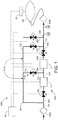
- Figure 1 illustrates an embodiment according to the invention comprising a system 1000 for leak testing a flexible expandable bag 500, wherein the system comprises a plurality of conduits (providing a plurality of fluid flow paths; one of the conduits has an end suitable for communication with a pressurized gas source, another conduit has an end suitable for communication with a port of the flexible expandable bag), a plurality of gas flow on/off valves (5 valves, valves V1, V2, V3, V4, and V5, are shown), a plurality of connectors, a gas flow meter 11, a gas pressure regulator 12, a pressure transducer 13, a pressure relief valve 14, a displacement sensor 20, and an apparatus 50 including a computer control unit.
- a plurality of conduits providing a plurality of fluid flow paths; one of the conduits has an end suitable for communication with a pressurized gas source, another conduit has an end suitable for communication with a port of the flexible expandable bag
- a plurality of gas flow on/off valves (5 valves, valves V1, V2,
- the apparatus 50 including the computer control unit controls operation of the gas on/off valves and gas flow through the fluid flow paths, and communicates with, and receives data from, the gas flow meter, the gas pressure regulator, the gas pressure transducer, and the displacement measurement sensor, regarding gas flow rate, gas pressure, and displacement of the flexible wall of the bag, to determine whether a leak is present.
- the broken and dotted lines show electrical connections with various components.
- One fluid flow path, 200 communicates with the pressurized gas source (and optionally, one or more sterilizing filters; in this illustrated embodiment, sterilizing filters 400a and 400b are shown) and flexible expandable bag 500 via conduits 100, 201, 202, 203, 204, 205, 206, 207, and 208), and allows gas passage through gas flow meter 11 and gas pressure controller 12, and communicates with pressure relief valve 13 and pressure transducer 14, passing through valves V1 and V4.
- sterilizing filter 400b can be part of a single-use bag system, rather than a component of system 1000.
- the embodiment of the system illustrated in Figure 1 provides at least one, and if desired, two, fluid flow paths bypassing the gas pressure regulator, wherein one of the fluid flow paths also bypasses the gas flow meter.
- a first bypass fluid flow path, 111a bypasses the gas flow meter 11 and the gas pressure controller 12, wherein the bypass fluid flow path 111a comprises conduit 101 (connected to conduit 100 via a connector that also connects with conduit 201), conduit 102 (connected to conduit 101 via a connector that also connects with conduit 110) and conduit 103 (connected to conduit 207 via a connector that also connects with conduit 206), and passing through valve V3.
- bypass fluid flow path 111b bypasses the gas flow meter 11, wherein bypass fluid flow path 111b comprises conduit 101 (connected to conduit 100 via a connector that also connects with conduit 201), conduit 110 (connected to conduit 101 via a connector that also connects with conduit 102), and conduit 112 (connected to conduit 204 via a connector that also connects with conduit 203), and passing through valve V2.
- Either or both of the bypass fluid flow paths can be utilized to quickly pass gas into the flexible expandable bag (while ensuring the pressure is less than the pressure at which the plastic in the flexible wall permanently deforms), before passing gas along fluid flow path 200 while measuring the flow rate of the gas into the bag while maintaining a constant pressure of the gas into the bag, measuring displacement of a flexible wall of the bag, and determining whether a leak is present.
- the illustrated system also shows a vent flow path, comprising conduit 209, and if desired, an optional sterilizing filter (not shown), allowing gas to be vented from the flexible bag after testing.
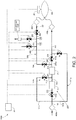
- Figure 2 illustrates another embodiment according to the invention comprising a system 1000 for leak testing a flexible expandable bag 500, wherein the system comprises a plurality of conduits (providing a plurality of fluid flow paths; one of the conduits has an end suitable for communication with a pressurized gas source, another conduit has an end suitable for communication with a port of the flexible expandable bag), a plurality of gas flow on/off valves (8 valves, valves V1, V2, V3, V4, V5A, V6, V7, and V8 are shown), a plurality of connectors, a gas flow meter 11, a gas pressure regulator 12, a pressure transducer 13, a pressure relief valve 14, a displacement sensor 20, and an apparatus 50 including a computer control unit.
- the system comprises a plurality of conduits (providing a plurality of fluid flow paths; one of the conduits has an end suitable for communication with a pressurized gas source, another conduit has an end suitable for communication with a port of the flexible expandable bag), a plurality of gas flow on
- the apparatus 50 including the computer control unit controls operation of the gas on/off valves and gas flow through the fluid flow paths, and communicates with, and receives data from, the gas flow meter, the gas pressure regulator, the gas pressure transducer, and the displacement measurement sensor, regarding gas flow rate, gas pressure, and displacement of the flexible wall of the bag, to determine whether a leak is present.
- the broken and dotted lines show electrical connections with various components.
- One fluid flow path, 200 communicates with the pressurized gas source (and optionally, sterilizing filters 400a and 400b) and flexible expandable bag 500 via conduits 100, 100a, 202, 203, 204, 205, 205a, 206, and 207), and allows gas passage through gas flow meter 11 and gas pressure controller 12, passing through valves V1 and V4.
- the embodiment of the system illustrated in Figure 2 provides at least one, and if desired, two, fluid flow paths bypassing the gas pressure regulator, wherein one of the fluid flow paths also bypasses the gas flow meter.
- a first bypass fluid flow path, 111a bypasses the gas flow meter 11 and the gas pressure controller 12, wherein the bypass fluid flow path 111a comprises conduit 101b (connected to conduit 101a via a connector that also connects with conduits 100 and 100a), and conduit 103a (connected to conduit 207 via a connector that also connects with conduit 206), and passing through valve V3.
- bypass fluid flow path 111b bypasses the gas flow meter 11, wherein bypass fluid flow path 111b comprises conduit 101a (connected to conduits 101b via a connector that also connects with conduits 100 and 100a), and conduit 112 (connected to conduit 204 via a connector that also connects with conduit 203), and passing through valve V2.
- Either or both of the bypass fluid flow paths can be utilized to quickly pass gas into the flexible expandable bag, before passing gas along fluid flow path 200 while controlling the flow rate of the gas into the bag while maintaining a constant pressure of the gas into the bag, measuring displacement of a flexible wall of the bag, and determining whether a leak is present.
- the illustrated system also shows a calibrated leak flow path 300, comprising conduit 301 (allowing gas to pass through optional sterilizing filter 400c), as well as conduits 302, 303, 304, 305, and 306, including an optional vent flow path, comprising conduit 309, and if desired, an optional sterilizing filter (not shown), allowing gas to be vented from the flexible bag after testing.
- a calibrated leak flow path 300 comprising conduit 301 (allowing gas to pass through optional sterilizing filter 400c), as well as conduits 302, 303, 304, 305, and 306, including an optional vent flow path, comprising conduit 309, and if desired, an optional sterilizing filter (not shown), allowing gas to be vented from the flexible bag after testing.
- Calibrated leak flow path 300 communicates with pressure relief valve 13 and pressure transducer 14.
- sterilizing filter 400b and/or sterilizing filter 400c can be part of a single-use bag system, rather than a component of system 1000.
- the bag is vented by introducing the liquid which vents the bag by displacing the gas.
- liquid e.g., cell culture fluid for some bioreactor or biocontainer applications
- the bag is vented using a variety of bioreactor/biocontainer fill systems.
- Figures 3A and 3B for reference, while the bag is in the tote after testing, liquid can be introduced into the bag, displacing the gas.
- FIG. 3C One example of an apparatus 2000 for venting is shown in Figure 3C , illustrating a flexible polymeric sheet 1250, a bag receiving device 1150 comprising a base 1100 comprising a surface 1101, and at least one raised wall 1110, the raised wall having a portion 1111 for allowing the sheet, and a flexible bag 500, to be secured to the bag receiving device.
- the illustrated bag receiving device also includes retainer 1130, wherein a portion 1111 of raised side wall 1110 includes slot or cut out 1133B, arranged in arm 1132B (the other arm 1132A also includes a slot or cut out (not shown)) attached to the side wall.
- Some commercially available bags include an element such as a rod or shaft that is engageable with the slots, allowing the bag to be secured to the bag receiving device (e.g., as shown in Figure 4 ).
- the retainer can further comprise a rod that is engageable with the slots to secure the bag 500 to the bag receiving device.
- a portion 1111 of raised side wall 1110 includes a slot or cut out 1120 for receiving an extension or "tongue" end 1155 of the flexible polymeric sheet 1250.
- the sheet can be secured to the base or side wall by a fastener such as a screw, nail, pin, rivet, bolt, clip, or clamp.
- the bag 500 illustrated in Figure 3C which has an interior volume, also includes a port 1210 and a conduit 1215 in fluid communication with the interior volume, wherein the illustrated bag is a 2D or pillow bag, having opposing flexible side walls 1201 and 1202 sealed at the edges and defining the interior volume therein.
- the sheet should be flexible in order to generally conform to the shape of the bag (or at least conforming to the shape of the flexible wall of the bag contacting the sheet.
- the sheet can be made from any suitable flexible material, typically a polymeric and/or elastomeric material, such as, for example, silicone, polyvinyl chloride (PVC), neoprene, nitrile rubber, VITON, and a terpolymer of ethylene, propylene and a diene, such as, for example, ethylene propylene diene terpolymer (EPDM).
- a suitable material is a general purpose silicone sheet available from Silex Silcones Ltd. (UK), as "silicone solid sheet.”
- the flexible polymeric sheet can have any density as long it is sufficient to compress and evacuate the gas-filled flexible bag when placed on a wall of the bag and the gas fluid flow path from the interior of the bag is opened.
- the sheet has a thickness in the range of from about 4 mm to about 20 mm, and a density in the range of from about 3 Kg/m 2 to about 15 Kg/m 2 .
- 0.31 m 2 x 9.6 Kg/m 2 2.97 Kg.
- a sheet having a greater thickness is used as compared to the thickness used when the bag has a lesser volume, e.g., about 5 to about 10 L.
- the sheet can have suitable size, shape, and/or configuration.
- the sheet can have essentially the same dimensions of the base of the bag receiving device, or can have portions cut away.
- the sheet should have a sufficient dimension to cover at least about 75% of the area, preferably at least about 90% of the area, of the flexible wall of the bag to be compressed.
- the sheet should not cover the port of the bag from which gas is to be evacuated.
- the flexible polymeric sheet 1250 is placed in contact with the upper wall of the gas filled flexible container 500, and the flow path passing through conduit 1215 leading to the port 1210 is opened (e.g., by opening a closed clamp on the conduit), and the bag is compressed, venting gas through the conduit.
- gas flow meters gas pressure regulators, gas pressure transducers, displacement measurement sensors, gas flow valves (including gas pressure relief valves), conduits, and apparatuses including computer control units (the apparatuses can have several components in a single housing, or can comprise one or more components in separate housings), and software programs, are suitable for use in the invention.
- suitable gas flow meters include, for example, thermal mass flow meters and coriolis mass flow meters;
- suitable gas pressure regulators include, for example, digital electronic pressure controllers, such as forward pressure controllers;
- suitable displacement measurement sensors include, for example, laser triangulation sensors (which do not require contact with the wall of the bag), linear variable differential transformers (LVDT; require contact with the wall of the bag), and capacitive displacement sensors (which do not require contact with the wall of the bag, but may require a metal surface, such as a lever arrangement);
- suitable software programs for analyzing data include, for example, Mathworks MATLAB.
- One example of a suitable apparatus including a computer control unit that can be adapted for use in accordance with embodiments of the invention is the PALLTRONIC® Flowstar LGR Test Instrument (Pall Corporation, Port Washington, NY).
- the displacement measurement sensor can be used in accordance with embodiments of the invention in a variety of arrangements and configurations.
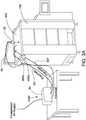
- the displacement sensor could be mounted over the biocontainer, measuring the displacement of the top surface, as illustratively shown in Figures 3A-3C , also showing a fixture 25 and the sensor 20.
- the sensor 20 could be supported on a fixture 25 that is mounted to a biocontainer tote 700 itself ( Figure 3A ), or the sensor could be mounted to a fixture 25 that is free standing on the floor next to the biocontainer tote 700 ( Figure 3B ).
- Figure 3C also showing a bag receiving device 1150, the sensor can be supported on a fixture mounted to the bag receiving device, or the sensor could be mounted to a fixture that is free standing next to the bag receiving device.
- the mounting of the sensor should be rigid to minimize vibration or other movement which could disrupt the displacement measurement.
- the fixture can have height adjustment in order to properly locate the displacement sensor in height over the biocontainer prior to the test to allow for biocontainer installation variance.
- an actuator can be used to adjust the height of the displacement sensor during the test (under control of the computer control unit).
- the system which is arranged as generally shown in Figures 1 and 3C (for 2D bags) includes the following: Solenoid gas flow valves (1 ⁇ 4 inch), including a pressure relief valve (a normally open solenoid valve linked to a pressure switch (SMC; ISE10-M5-B; wired so that the electrical signal to the normally open valve is cut if the pressure rises above the pressure switch operating pressure) connected with flexible nylon tubing and compression fittings; a thermal mass flow meter (Bronkhorst Low- ⁇ P-Flow; F-101-AGD-22-V, range 50-2,500 seem), a gas pressure controller (Bronkhorst EL Press; P-602CV-350R-AGD-22-V, regulatable from 5-100 mbar), a gas pressure sensor (Vegabar; BAR14.X1SA1GV1, range from 0-100 mbar), a laser triangulation displacement sensor (Micro-Epsilon; ILD2300-50LL, at 50 mm range, resolution 0.8 ⁇ m,
- the pressure relief valve is set to operate at a pressure of 60 mbar, which is above the test pressure of 50 mbar, but below the pressure at which the biocontainer would burst.
- the use of at least one fluid flow path bypassing the gas flow meter to pass gas into the flexible bag allows the flexible bag to be filled more quickly. If desired, the initial bypassing flow may exceed the maximum measurement range of the gas flow meter.
- 2D 50L bags are tested using a test pressure of 50 mbar.
- An opaque patch is placed on the upper surface of the bag such that the patch is aligned with the laser triangulation displacement sensor for displacement measurement.
- a compressed gas supply regulated to about 1 bar, is connected to the inlet of the system via one sterilizing filter and the outlet of the system is connected via another sterilizing filter to a convenient port on the biocontainer under test via flexible tubing.
- Valve V3 is opened (V1, V2, V4, andV5 are closed) to allow gas to flow through the fill line via bypass fluid path 111a to rapidly fill the biocontainer to the test pressure.
- valve V3 is closed, and valves V2 and V4 are opened to route flow through bypass fluid path 111b around the gas flow meter and through the gas pressure controller.
- valve V1 is opened to allow flow through the gas flow meter, and then valve V2 is closed, such that gas flows along fluid flow path 200.
- the set point for the gas pressure controller is provided from the computer system. The pressure set point is compensated for the pressure drop along the flexible tubing at the measured gas flow rate, to give the 50 mbar test pressure in the biocontainer.
- Test measurements are started when the test pressure is reached.
- the gas flow rate through the gas flow meter and the change in dimension of the biocontainer are measured at regular intervals from the start of the test, over a period of 10 - 30 minutes.
- the gas flow rate is numerically integrated with respect to time from the start of the test to each point in time, to give the volume of gas added to the biocontainer at time t.
- the leakage flow is calculated using the formula provided above. Since there is an initial increase from zero in flow rate when the gas is passed through the gas flow meter, the linear regression is carried out from the time when the flow rate starts to decrease from a maximum value through to the end of the test.
- the biocontainer is vented by opening valve V5, and closing valves V1, V2 and V3, followed by V4.
- the flexible tubing is disconnected from the test system and, if no leak is detected, the biocontainer can be put into the production process.
- the 2D bag has a volume of 120 L.
- the system and method of testing is as generally described in Example 1.
- An opaque patch is placed on the upper surface of the bag such that the patch is aligned with the laser triangulation displacement sensor for displacement measurement.
- the flow required to maintain this pressure while the biocontainer expands is measured along with the displacement of one flexible wall.
- the integral of the flow into the biocontainer i.e. the volume added
- the integral of the flow into the biocontainer is proportional to the biocontainer expansion in one dimension, as measured by the displacement sensor.
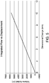
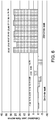
- the dimensional change of the bag (the measurement of the distance that the flexible bag wall moves when expanding in a direction perpendicular or close to perpendicular to the wall) changes as a function of time during a leak test. As shown in Figure 4 , the dimensional change of the bag (the measurement of the distance that the flexible bag wall moves when expanding in a direction perpendicular or close to perpendicular to the wall) changes as a function of time during a leak test. As shown in Figure 4 , the dimensional change of the bag (the measurement of the distance that the flexible bag wall moves when expanding in a direction perpendicular or close to perpendicular to the wall) changes as a function of time during a leak test. As shown in Figure 4 , the dimensional change of the bag (the measurement of the distance that the flexible bag wall moves when expanding in a direction perpendicular or close to perpendicular to the wall) changes as a function of time during a leak test. As shown in Figure 4 , the dimensional change of the bag (the measurement of the distance that
- gas volume added (integration of flow rate with respect to time) is proportional to the displacement (expansion in one dimension) of the bag in the absence of a leak.
- This example demonstrates leak testing in accordance with another embodiment of the invention, both when a leak is not present, and when a calibrated leak is present, using 2D bags.
- the system which is arranged as generally shown in Figures 2 and 3C , generally includes the components as described in Example 1.
- Valve V5A is installed on a branch upstream of valve V4 and the second connection is installed after valve V5A and valve V6 is used to isolate the second connection from the biocontainer.
- a vent is included as a branch in the second line, via valve V7, and a further branch in the line is connected to a calibrated leak for test purposes, via valve V8.
- 2D 120L bags are tested using a test pressure of 50 mbar.
- valves V3 and V6 (V1, V2, V4, V5A, V7, and V8 are closed) to allow gas to flow along first bypass fluid flow path 111a to rapidly fill the biocontainer to a test pressure of 50 mbar.
- Valve V6 is opened, to allow the pressure in the biocontainer to be verified using the gas pressure transducer.
- valve V3 is closed, and valves V2 and V4 are opened to route flow through second bypass fluid flow path 111b around the gas flow meter and through the gas pressure controller.
- valve V1 is opened to allow flow through the gas flow meter along fluid flow path 200, and then valve V2 is closed.
- the set point of 50 mbar for the gas pressure controller is provided from the computer system.
- Test measurements are started when the test pressure is reached and stable.
- the gas flow rate through the gas flow meter and the change in dimension of the biocontainer are measured at regular intervals from the start of the test, over a period of 10 - 30 minutes.
- valve V8 is opened after valve V1 is opened and V2 is closed.
- the flow through the calibrated leak is measured independently by opening valves V1, V5A, V8, with valves V2, V3, V4, V6 and V7 remaining closed.
- the leakage flow is calculated using the formula provided above. Since there is an initial increase from zero in flow rate when the gas is passed through the gas flow meter, the linear regression is carried out from the time when the flow rate starts to decrease from a maximum value through to the end of the test.
- Figure 6 shows the measured values when no leak is present, and when a calibrated leak giving a flow rate of 29 sccm (ml/min) is present, at a differential pressure of 50 mbar.
- This example demonstrates leak testing in accordance with another embodiment of the invention, both when a leak is not present, and when a calibrated leak is present, using 3D bags in a tote.
- the system which is arranged as generally shown in Figures 2 and 3B , generally includes the components as described in Example 1.
- Valve V5A is installed on a branch upstream of valve V4 and the second connection is installed after valve V5A and valve V6 is used to isolate the second connection from the biocontainer.
- a vent is included as a branch in the second line, via valve V7, and a further branch in the line is connected to a calibrated leak for test purposes, via valve V8.
- 3D 1000L bags are tested (in a tote) using a test pressure of 25 mbar.
- An opaque patch is placed on the upper (top) surface of the bag such that the patch is aligned with the laser triangulation displacement sensor for displacement measurement.
- valves V3 and V6 (V1, V2, V4, V5A, V7, and V8 are closed) to allow gas to flow along first bypass fluid flow path 111a to rapidly fill the biocontainer to a test pressure of 25 mbar.
- Valve V6 is opened, to allow the pressure in the biocontainer to be verified using the gas pressure transducer.
- valve V3 is closed, and valves V2 and V4 are opened to route flow through second bypass fluid flow path 111b around the gas flow meter and through the gas pressure controller.
- valve V1 is opened to allow flow through the gas flow meter along fluid flow path 200, and then valve V2 is closed.
- the set point of 25 mbar for the gas pressure controller is provided from the computer system.
- Test measurements are started when the test pressure is reached and stable.
- the gas flow rate through the gas flow meter and the change in dimension of the biocontainer are measured at regular intervals from the start of the test, over a period of 10 - 30 minutes.
- valve V8 is opened after valve V1 is opened and V2 is closed.
- the flow through the calibrated leak is measured independently by opening valves V1, V5A, V8, with valves V2, V3, V4, V6 and V7 remaining closed.
- the leakage flow is calculated using the formula provided above. Since there is an initial increase from zero in flow rate when the gas is passed through the gas flow meter, the linear regression is carried out from the time when the flow rate starts to decrease from a maximum value through to the end of the test.
- Figure 7 shows the measured values when no leak is present, and when a calibrated leak giving a flow rate of 95 sccm (ml/min) is present, at a differential pressure of 25 mbar.
Landscapes
- Physics & Mathematics (AREA)
- General Physics & Mathematics (AREA)
- Engineering & Computer Science (AREA)
- Mathematical Physics (AREA)
- Theoretical Computer Science (AREA)
- Data Mining & Analysis (AREA)
- Computational Mathematics (AREA)
- Mathematical Optimization (AREA)
- Mathematical Analysis (AREA)
- Pure & Applied Mathematics (AREA)
- Databases & Information Systems (AREA)
- Software Systems (AREA)
- General Engineering & Computer Science (AREA)
- Algebra (AREA)
- Examining Or Testing Airtightness (AREA)
- Medical Preparation Storing Or Oral Administration Devices (AREA)
Claims (8)
- Verfahren zur Leckprüfung eines flexiblen, expandierbaren Beutels (500) mit mindestens einem Port und mindestens einer flexiblen Wandung, wobei das Verfahren umfasst:(a) Füllen des flexiblen Beutels (500) mit Gas, welches den mindestens einen Port durchströmt, derart, dass der flexible Beutel (500) expandiert, wobei das Füllen des flexiblen Beutels (500) ein Messen einer Flussrate des Gases in den flexiblen Beutel (500) hinein unter Aufrechterhaltung eines konstanten Drucks des Gases in dem flexiblen Beutel (500) umfasst;(b) Messen einer Verschiebung der flexiblen Wandung; und(c) Bestimmen, ob ein Leck vorhanden ist,dadurch gekennzeichnet, dass das Bestimmen, ob ein Leck vorhanden ist, das Anwenden der Formel

worinQ die gemessene Flussrate in den Beutel zum Zeitpunkt t istK eine Konstante ist, welche die Dimensionsänderung in Beziehung zu der Volumenvergrößerung des Beutels setztd die Dimensionsänderung zum Zeitpunkt t istL der Fluss aus dem Leck ist, falls vorhanden; wobei L = 0, wenn kein Leck vorhanden ist. - Verfahren nach Anspruch 1, umfassend: anfängliches Einleiten von Gas in den flexiblen Beutel (500) über einen ersten Fluidströmungspfad (lila), welcher einen Gasdurchflussmesser (11) und/oder einen Gasdruckregler (12) umgeht, bevor Gas unter Verwendung eines zweiten Fluidströmungspfads (111b) durch den Gasdurchflussmesser (11) und den Gasdruckregler (12) hindurch in den flexiblen Beutel (500) hinein geleitet wird.
- Verfahren nach Anspruch 1 oder 2, umfassend: Aufrechterhalten eines konstanten Gasdrucks von mindestens ungefähr 10 mbar.
- Verfahren nach Anspruch 1 oder 2, umfassend: Aufrechterhalten eines konstanten Gasdrucks im Bereich von ungefähr 10 mbar bis ungefähr 50 mbar.
- Verfahren nach einem der Ansprüche 1 bis 4, umfassend: Entlüften des flexiblen Beutels (500) nach dem Bestimmen, ob ein Leck vorhanden ist.
- Verfahren nach einem der Ansprüche 1 bis 5, umfassend ein Sterilverfahren, wobei das Verfahren umfasst: Leiten von Gas von einer Quelle für unter Druck stehendes Gas durch mindestens ein Filter in Sterilqualität, bevor das Gas in den flexiblen Beutel (500) hinein geleitet wird.
- System (1000) zur Leckprüfung eines flexiblen, expandierbaren Beutels (500) mit mindestens einem Port und mindestens einer flexiblen Wandung, umfassend:(a) einen Gasdurchflussmesser (11);(b) einen Gasdruckregler (12);(c) einen Gasdruckwandler (13);(d) ein Gasdruckentlastungsventil (14);(e) einen Verschiebungsmesssensor (20), welcher dazu angeordnet ist, bei Expansion des Beutels unter Befüllung mit Gas eine Verschiebung der flexiblen Wandung des Beutels (500) zu messen;(f) mindestens drei Ventile (V1, V2, V3, V4, V5), wobei jedes Ventil steuerbar ist, um einen Gasstrom durch dieses hindurch zuzulassen oder zu verhindern;(g) eine Mehrzahl von Leitungen (100, 201, 202, 203, 204, 205, 206, 207, 208), welche dazu angeordnet sind, einen ersten Fluidströmungspfad (lila) von einer Quelle für unter Druck stehendes Gas zu dem flexiblen, expandierbaren Beutel (500) bereitzustellen, wobei der erste Fluidströmungspfad (lila) den Gasdurchflussmesser (11) und/oder den Gasdruckregler (12) umgeht, und einen zweiten Fluidströmungspfad (111b) von der Quelle für unter Druck stehendes Gas zu dem flexiblen, expandierbaren Beutel (500), wobei der zweite Fluidströmungspfad (111b) durch den Gasdurchflussmesser (11) und den Gasdruckregler (12) hindurch geht, der erste Fluidströmungspfad (lila) und der zweite Fluidströmungspfad (111b) jeweils durch mindestens eines der drei Ventile (V2, V3) hindurch gehen, wobei der zweite Fluidströmungspfad mit dem Gasdruckwandler und dem Gasdruckentlastungsventil (14) in Verbindung steht, und wobei mindestens eine Leitung der Mehrzahl von Leitungen ein Ende aufweist, welches mit dem mindestens einen Port (1210) des flexiblen, expandierbaren Beutels in Verbindung bringbar ist; und(h) eine Vorrichtung (50) mit einer Computersteuereinheit, wobei die Vorrichtung (50) den Betrieb der Ventile und den Gasstrom durch den ersten Fluidströmungspfad (lila) und den zweiten Fluidströmungspfad (111b) hindurch steuert, wobei die Vorrichtung (50) mit dem Gasdurchflussmesser (11), dem Gasdruckregler (12), dem Gasdruckwandler (13) und dem Verschiebungsmesssensor (20) in Verbindung steht und Daten von diesen betreffend Gasflussrate, Gasdruck und Verschiebung der flexiblen Wandung des Beutels empfängt, um zu bestimmen, ob ein Leck vorhanden ist, wobei die Computersteuereinheit programmiert ist, eine lineare Regression durchzuführen und unter Verwendung der folgenden Formel zu bestimmen, ob ein Leck vorhanden ist:
 Q die gemessene Flussrate in den Beutel zum Zeitpunkt t istK eine Konstante ist, welche eine Dimensionsänderung in Beziehung zu der Volumenvergrößerung des Beutels setztd die Dimensionsänderung zum Zeitpunkt t istL der Fluss aus dem Leck ist, falls vorhanden; wobei L = 0 , wenn kein Leck vorhanden ist.
 - System nach Anspruch 7, ferner umfassend:
(i) mindestens ein Filter in Sterilqualität in Fluidverbindung mit der Quelle für unter Druck stehendes Gas und dem ersten Fluidströmungspfad (lila) und dem zweiten Fluidströmungspfad (111b).
Applications Claiming Priority (1)
| Application Number | Priority Date | Filing Date | Title |
|---|---|---|---|
| US15/372,595 US10422716B2 (en) | 2016-12-08 | 2016-12-08 | Method and system for leak testing |
Publications (2)
| Publication Number | Publication Date |
|---|---|
| EP3333560A1 EP3333560A1 (de) | 2018-06-13 |
| EP3333560B1 true EP3333560B1 (de) | 2019-12-25 |
Family
ID=60244985
Family Applications (1)
| Application Number | Title | Priority Date | Filing Date |
|---|---|---|---|
| EP17199909.7A Active EP3333560B1 (de) | 2016-12-08 | 2017-11-03 | Verfahren und system zur leckprüfung |
Country Status (6)
| Country | Link |
|---|---|
| US (1) | US10422716B2 (de) |
| EP (1) | EP3333560B1 (de) |
| JP (1) | JP6561359B2 (de) |
| KR (1) | KR101954929B1 (de) |
| CN (1) | CN108168803B (de) |
| AU (1) | AU2017245475B2 (de) |
Families Citing this family (11)
| Publication number | Priority date | Publication date | Assignee | Title |
|---|---|---|---|---|
| KR200490385Y1 (ko) * | 2018-06-26 | 2019-11-05 | 주식회사 한국가스기술공사 | 볼밸브의 누설시험장치 |
| JP6819655B2 (ja) * | 2018-07-12 | 2021-01-27 | 大日本印刷株式会社 | エア注入装置 |
| US11927503B2 (en) | 2018-09-21 | 2024-03-12 | Cytiva Sweden Ab | Method for determining a weld integrity test result |
| EP3690419B1 (de) * | 2019-02-01 | 2021-11-03 | Sartorius Stedim Fmt Sas | System und verfahren zur erfassung eines möglichen integritätsverlustes einer flexiblen tasche für biopharmazeutische produkte |
| CN109764944B (zh) * | 2019-03-04 | 2020-12-25 | 常州市成丰流量仪表有限公司 | 电磁流量计全自动试压装置及试压方法 |
| CN110044552B (zh) * | 2019-05-23 | 2020-12-11 | 北京锐业制药有限公司 | 粉-液双室袋铝膜焊接密封性检漏装置 |
| CN110823708A (zh) * | 2019-11-20 | 2020-02-21 | 迈海(苏州)环保科技有限公司 | 柔性滤管的极限疲劳测试装置及测试方法 |
| JP7294165B2 (ja) * | 2020-01-24 | 2023-06-20 | トヨタ自動車株式会社 | ケースの気密性の評価方法及び評価装置 |
| US12013279B2 (en) * | 2020-04-06 | 2024-06-18 | Kane Usa, Inc. | Volume fill airflow measurement |
| DE102020003418A1 (de) * | 2020-06-05 | 2021-12-09 | W.O.M. World Of Medicine Gmbh | Verfahren zur Bestimmung von Kavitätsvolumen von elastischen Medizinprodukten zur Dichtigkeitsprüfung |
| CN115342997A (zh) * | 2022-09-02 | 2022-11-15 | 百林科制药装备科技(江苏)有限公司 | 可视化柔性测漏法及其柔性包裹测具 |
Family Cites Families (24)
| Publication number | Priority date | Publication date | Assignee | Title |
|---|---|---|---|---|
| US3683677A (en) * | 1970-06-22 | 1972-08-15 | David S Harris | Leak detector |
| US4364261A (en) * | 1981-03-25 | 1982-12-21 | N.E.R.G. Enterprises, Inc. | Multi-media leak test apparatus |
| JPH0257533A (ja) | 1988-08-22 | 1990-02-27 | Taiyo Fishery Co Ltd | 密閉容器のリーク検査方法 |
| US4899574A (en) | 1989-02-01 | 1990-02-13 | The Mead Corporation | Method and apparatus for detecting leaks in a sealed container |
| JPH0692921B2 (ja) | 1990-02-21 | 1994-11-16 | 株式会社コスモ計器 | 洩れのある風袋の内容積及び洩れ量測定方法及びこの測定方法を用いた測定装置 |
| DE4017693C2 (de) | 1990-06-01 | 1995-11-16 | Martin Lehmann | Leckageprüfung |
| US5113705A (en) * | 1990-12-21 | 1992-05-19 | Siemens Automotive L.P. | Functional testing of solenoid valves in air |
| JPH10142098A (ja) * | 1996-11-13 | 1998-05-29 | Cosmo Keiki:Kk | 可撓性容器の洩れ検査方法及び装置 |
| EP0791814A3 (de) * | 1997-05-26 | 1997-11-26 | Martin Lehmann | Verfahren zum Prüfen von Leck und Apparat zum Testen von Leck |
| US6330823B1 (en) | 1998-01-13 | 2001-12-18 | Benthos, Inc. | Process and apparatus for testing containers |
| US6253919B1 (en) | 1998-04-13 | 2001-07-03 | Sealed Air Corporation | Inflatable packing material |
| US6952963B2 (en) * | 2003-05-23 | 2005-10-11 | Gambro Dasco S.P.A. | Method for detecting a liquid level in a container in a circuit and a dialysis machine for actuating the method |
| JP4353860B2 (ja) | 2004-06-24 | 2009-10-28 | 株式会社エヌテック | 容器の検査方法及び装置 |
| JP4316446B2 (ja) * | 2004-08-12 | 2009-08-19 | コーンズドッドウェル株式会社 | バッグ容器の注入口シール部の漏れ検査方法 |
| US20060037382A1 (en) * | 2004-08-18 | 2006-02-23 | Falchi Mauro C | Method and apparatus to detect leaks in expansion vessel |
| JP4630791B2 (ja) | 2005-10-17 | 2011-02-09 | 株式会社フクダ | 流量式性能検査方法 |
| US8658107B2 (en) * | 2008-08-20 | 2014-02-25 | Panasonic Healthcare Co., Ltd. | Isolator |
| EP2244091B8 (de) * | 2009-04-21 | 2016-02-24 | Agilent Technologies, Inc. | Einem Mischpunkt vorgelagerte Lecksuche |
| JP5620184B2 (ja) * | 2010-08-03 | 2014-11-05 | 株式会社エー・シー・イー | 漏れ検査装置及び漏れ検査方法 |
| CH704550A2 (de) | 2011-02-21 | 2012-08-31 | Texa Ag | Verfahren und Vorrichtung zum Prüfen der Dichtigkeit von Dosen. |
| DE102011106165B4 (de) | 2011-06-30 | 2015-07-02 | Sartorius Stedim Biotech Gmbh | Prüfverfahren und -vorrichtung für Bioreaktorbehälter sowie Verwendung |
| US8534120B1 (en) | 2012-09-14 | 2013-09-17 | Advanced Scientifics, Inc. | Test system and method for flexible containers |
| US9663259B2 (en) | 2015-02-27 | 2017-05-30 | Pall Corporation | Gas evacuation system and method |
| CN105712070A (zh) * | 2015-10-29 | 2016-06-29 | 山东明佳科技有限公司 | 包装袋泄露检测设备及方法 |
-
2016
- 2016-12-08 US US15/372,595 patent/US10422716B2/en active Active
-
2017
- 2017-10-12 JP JP2017198529A patent/JP6561359B2/ja active Active
- 2017-10-16 AU AU2017245475A patent/AU2017245475B2/en active Active
- 2017-11-03 EP EP17199909.7A patent/EP3333560B1/de active Active
- 2017-11-07 CN CN201711081510.6A patent/CN108168803B/zh active Active
- 2017-11-17 KR KR1020170153827A patent/KR101954929B1/ko active Active
Non-Patent Citations (1)
| Title |
|---|
| None * |
Also Published As
| Publication number | Publication date |
|---|---|
| KR101954929B1 (ko) | 2019-03-06 |
| KR20180065894A (ko) | 2018-06-18 |
| EP3333560A1 (de) | 2018-06-13 |
| CN108168803A (zh) | 2018-06-15 |
| AU2017245475A1 (en) | 2018-06-28 |
| US20180164180A1 (en) | 2018-06-14 |
| JP6561359B2 (ja) | 2019-08-21 |
| JP2018096975A (ja) | 2018-06-21 |
| CN108168803B (zh) | 2019-12-10 |
| AU2017245475B2 (en) | 2018-11-15 |
| US10422716B2 (en) | 2019-09-24 |
Similar Documents
| Publication | Publication Date | Title |
|---|---|---|
| AU2017245475B2 (en) | Method and system for leak testing | |
| US9528905B2 (en) | Test system and method for flexible containers | |
| CN114096822B (zh) | 用于验证柔性袋的完整性的测试系统和测试方法 | |
| EP1356260B2 (de) | Produktleckprüfung | |
| US20080213874A1 (en) | Weight measurements of liquids in flexible containers | |
| US20120031042A1 (en) | Disposable isolator comprising means for filling containers | |
| JP7853098B2 (ja) | バイオ医薬品用の可撓性バッグの完全性の喪失の可能性を検出するためのシステムおよび方法 | |
| CN104237078B (zh) | 一种测量多孔粉末内分子扩散系数的方法和装置 | |
| WO2003071247A1 (en) | Chemically inert flow control with non-contaminating body | |
| TWI721131B (zh) | 被檢查容器的漏洩檢查方法以及漏洩檢查裝置 | |
| CN107257917A (zh) | 用于容器的密封性检验的组件和方法 | |
| KR20200047648A (ko) | 엠보싱된 필름 바이오프로세싱 용기 및 바이오프로세싱 용기의 완전성 시험 | |
| US11498024B2 (en) | Method and system for recovering fluid | |
| CN218444353U (zh) | 一种微泄漏密封性测试仪 | |
| ES2946682T3 (es) | Dispositivo de administración de líquido microfluídico | |
| US11173434B2 (en) | Method and system for recovering fluid | |
| CN114235103A (zh) | 质量流量计校准系统 |
Legal Events
| Date | Code | Title | Description |
|---|---|---|---|
| PUAI | Public reference made under article 153(3) epc to a published international application that has entered the european phase |
Free format text: ORIGINAL CODE: 0009012 |
|
| STAA | Information on the status of an ep patent application or granted ep patent |
Free format text: STATUS: THE APPLICATION HAS BEEN PUBLISHED |
|
| AK | Designated contracting states |
Kind code of ref document: A1 Designated state(s): AL AT BE BG CH CY CZ DE DK EE ES FI FR GB GR HR HU IE IS IT LI LT LU LV MC MK MT NL NO PL PT RO RS SE SI SK SM TR |
|
| AX | Request for extension of the european patent |
Extension state: BA ME |
|
| STAA | Information on the status of an ep patent application or granted ep patent |
Free format text: STATUS: REQUEST FOR EXAMINATION WAS MADE |
|
| 17P | Request for examination filed |
Effective date: 20180924 |
|
| RBV | Designated contracting states (corrected) |
Designated state(s): AL AT BE BG CH CY CZ DE DK EE ES FI FR GB GR HR HU IE IS IT LI LT LU LV MC MK MT NL NO PL PT RO RS SE SI SK SM TR |
|
| GRAP | Despatch of communication of intention to grant a patent |
Free format text: ORIGINAL CODE: EPIDOSNIGR1 |
|
| STAA | Information on the status of an ep patent application or granted ep patent |
Free format text: STATUS: GRANT OF PATENT IS INTENDED |
|
| INTG | Intention to grant announced |
Effective date: 20190301 |
|
| GRAS | Grant fee paid |
Free format text: ORIGINAL CODE: EPIDOSNIGR3 |
|
| GRAJ | Information related to disapproval of communication of intention to grant by the applicant or resumption of examination proceedings by the epo deleted |
Free format text: ORIGINAL CODE: EPIDOSDIGR1 |
|
| GRAL | Information related to payment of fee for publishing/printing deleted |
Free format text: ORIGINAL CODE: EPIDOSDIGR3 |
|
| STAA | Information on the status of an ep patent application or granted ep patent |
Free format text: STATUS: REQUEST FOR EXAMINATION WAS MADE |
|
| GRAP | Despatch of communication of intention to grant a patent |
Free format text: ORIGINAL CODE: EPIDOSNIGR1 |
|
| STAA | Information on the status of an ep patent application or granted ep patent |
Free format text: STATUS: GRANT OF PATENT IS INTENDED |
|
| INTG | Intention to grant announced |
Effective date: 20190301 |
|
| INTC | Intention to grant announced (deleted) | ||
| INTG | Intention to grant announced |
Effective date: 20190627 |
|
| GRAA | (expected) grant |
Free format text: ORIGINAL CODE: 0009210 |
|
| STAA | Information on the status of an ep patent application or granted ep patent |
Free format text: STATUS: THE PATENT HAS BEEN GRANTED |
|
| AK | Designated contracting states |
Kind code of ref document: B1 Designated state(s): AL AT BE BG CH CY CZ DE DK EE ES FI FR GB GR HR HU IE IS IT LI LT LU LV MC MK MT NL NO PL PT RO RS SE SI SK SM TR |
|
| REG | Reference to a national code |
Ref country code: GB Ref legal event code: FG4D |
|
| REG | Reference to a national code |
Ref country code: CH Ref legal event code: EP |
|
| REG | Reference to a national code |
Ref country code: DE Ref legal event code: R096 Ref document number: 602017010053 Country of ref document: DE |
|
| REG | Reference to a national code |
Ref country code: AT Ref legal event code: REF Ref document number: 1217646 Country of ref document: AT Kind code of ref document: T Effective date: 20200115 |
|
| REG | Reference to a national code |
Ref country code: IE Ref legal event code: FG4D |
|
| REG | Reference to a national code |
Ref country code: NL Ref legal event code: FP |
|
| REG | Reference to a national code |
Ref country code: SE Ref legal event code: TRGR |
|
| PG25 | Lapsed in a contracting state [announced via postgrant information from national office to epo] |
Ref country code: FI Free format text: LAPSE BECAUSE OF FAILURE TO SUBMIT A TRANSLATION OF THE DESCRIPTION OR TO PAY THE FEE WITHIN THE PRESCRIBED TIME-LIMIT Effective date: 20191225 Ref country code: BG Free format text: LAPSE BECAUSE OF FAILURE TO SUBMIT A TRANSLATION OF THE DESCRIPTION OR TO PAY THE FEE WITHIN THE PRESCRIBED TIME-LIMIT Effective date: 20200325 Ref country code: LT Free format text: LAPSE BECAUSE OF FAILURE TO SUBMIT A TRANSLATION OF THE DESCRIPTION OR TO PAY THE FEE WITHIN THE PRESCRIBED TIME-LIMIT Effective date: 20191225 Ref country code: GR Free format text: LAPSE BECAUSE OF FAILURE TO SUBMIT A TRANSLATION OF THE DESCRIPTION OR TO PAY THE FEE WITHIN THE PRESCRIBED TIME-LIMIT Effective date: 20200326 Ref country code: NO Free format text: LAPSE BECAUSE OF FAILURE TO SUBMIT A TRANSLATION OF THE DESCRIPTION OR TO PAY THE FEE WITHIN THE PRESCRIBED TIME-LIMIT Effective date: 20200325 Ref country code: LV Free format text: LAPSE BECAUSE OF FAILURE TO SUBMIT A TRANSLATION OF THE DESCRIPTION OR TO PAY THE FEE WITHIN THE PRESCRIBED TIME-LIMIT Effective date: 20191225 |
|
| REG | Reference to a national code |
Ref country code: LT Ref legal event code: MG4D |
|
| PG25 | Lapsed in a contracting state [announced via postgrant information from national office to epo] |
Ref country code: RS Free format text: LAPSE BECAUSE OF FAILURE TO SUBMIT A TRANSLATION OF THE DESCRIPTION OR TO PAY THE FEE WITHIN THE PRESCRIBED TIME-LIMIT Effective date: 20191225 Ref country code: HR Free format text: LAPSE BECAUSE OF FAILURE TO SUBMIT A TRANSLATION OF THE DESCRIPTION OR TO PAY THE FEE WITHIN THE PRESCRIBED TIME-LIMIT Effective date: 20191225 |
|
| PG25 | Lapsed in a contracting state [announced via postgrant information from national office to epo] |
Ref country code: AL Free format text: LAPSE BECAUSE OF FAILURE TO SUBMIT A TRANSLATION OF THE DESCRIPTION OR TO PAY THE FEE WITHIN THE PRESCRIBED TIME-LIMIT Effective date: 20191225 |
|
| PG25 | Lapsed in a contracting state [announced via postgrant information from national office to epo] |
Ref country code: RO Free format text: LAPSE BECAUSE OF FAILURE TO SUBMIT A TRANSLATION OF THE DESCRIPTION OR TO PAY THE FEE WITHIN THE PRESCRIBED TIME-LIMIT Effective date: 20191225 Ref country code: CZ Free format text: LAPSE BECAUSE OF FAILURE TO SUBMIT A TRANSLATION OF THE DESCRIPTION OR TO PAY THE FEE WITHIN THE PRESCRIBED TIME-LIMIT Effective date: 20191225 Ref country code: PT Free format text: LAPSE BECAUSE OF FAILURE TO SUBMIT A TRANSLATION OF THE DESCRIPTION OR TO PAY THE FEE WITHIN THE PRESCRIBED TIME-LIMIT Effective date: 20200520 Ref country code: EE Free format text: LAPSE BECAUSE OF FAILURE TO SUBMIT A TRANSLATION OF THE DESCRIPTION OR TO PAY THE FEE WITHIN THE PRESCRIBED TIME-LIMIT Effective date: 20191225 |
|
| PG25 | Lapsed in a contracting state [announced via postgrant information from national office to epo] |
Ref country code: SK Free format text: LAPSE BECAUSE OF FAILURE TO SUBMIT A TRANSLATION OF THE DESCRIPTION OR TO PAY THE FEE WITHIN THE PRESCRIBED TIME-LIMIT Effective date: 20191225 Ref country code: IS Free format text: LAPSE BECAUSE OF FAILURE TO SUBMIT A TRANSLATION OF THE DESCRIPTION OR TO PAY THE FEE WITHIN THE PRESCRIBED TIME-LIMIT Effective date: 20200425 Ref country code: SM Free format text: LAPSE BECAUSE OF FAILURE TO SUBMIT A TRANSLATION OF THE DESCRIPTION OR TO PAY THE FEE WITHIN THE PRESCRIBED TIME-LIMIT Effective date: 20191225 |
|
| REG | Reference to a national code |
Ref country code: DE Ref legal event code: R097 Ref document number: 602017010053 Country of ref document: DE |
|
| PG25 | Lapsed in a contracting state [announced via postgrant information from national office to epo] |
Ref country code: ES Free format text: LAPSE BECAUSE OF FAILURE TO SUBMIT A TRANSLATION OF THE DESCRIPTION OR TO PAY THE FEE WITHIN THE PRESCRIBED TIME-LIMIT Effective date: 20191225 Ref country code: DK Free format text: LAPSE BECAUSE OF FAILURE TO SUBMIT A TRANSLATION OF THE DESCRIPTION OR TO PAY THE FEE WITHIN THE PRESCRIBED TIME-LIMIT Effective date: 20191225 |
|
| PLBE | No opposition filed within time limit |
Free format text: ORIGINAL CODE: 0009261 |
|
| STAA | Information on the status of an ep patent application or granted ep patent |
Free format text: STATUS: NO OPPOSITION FILED WITHIN TIME LIMIT |
|
| REG | Reference to a national code |
Ref country code: AT Ref legal event code: MK05 Ref document number: 1217646 Country of ref document: AT Kind code of ref document: T Effective date: 20191225 |
|
| PG25 | Lapsed in a contracting state [announced via postgrant information from national office to epo] |
Ref country code: SI Free format text: LAPSE BECAUSE OF FAILURE TO SUBMIT A TRANSLATION OF THE DESCRIPTION OR TO PAY THE FEE WITHIN THE PRESCRIBED TIME-LIMIT Effective date: 20191225 |
|
| 26N | No opposition filed |
Effective date: 20200928 |
|
| PG25 | Lapsed in a contracting state [announced via postgrant information from national office to epo] |
Ref country code: AT Free format text: LAPSE BECAUSE OF FAILURE TO SUBMIT A TRANSLATION OF THE DESCRIPTION OR TO PAY THE FEE WITHIN THE PRESCRIBED TIME-LIMIT Effective date: 20191225 |
|
| PG25 | Lapsed in a contracting state [announced via postgrant information from national office to epo] |
Ref country code: PL Free format text: LAPSE BECAUSE OF FAILURE TO SUBMIT A TRANSLATION OF THE DESCRIPTION OR TO PAY THE FEE WITHIN THE PRESCRIBED TIME-LIMIT Effective date: 20191225 |
|
| PG25 | Lapsed in a contracting state [announced via postgrant information from national office to epo] |
Ref country code: MC Free format text: LAPSE BECAUSE OF FAILURE TO SUBMIT A TRANSLATION OF THE DESCRIPTION OR TO PAY THE FEE WITHIN THE PRESCRIBED TIME-LIMIT Effective date: 20191225 |
|
| REG | Reference to a national code |
Ref country code: CH Ref legal event code: PL |
|
| PG25 | Lapsed in a contracting state [announced via postgrant information from national office to epo] |
Ref country code: LU Free format text: LAPSE BECAUSE OF NON-PAYMENT OF DUE FEES Effective date: 20201103 |
|
| PG25 | Lapsed in a contracting state [announced via postgrant information from national office to epo] |
Ref country code: CH Free format text: LAPSE BECAUSE OF NON-PAYMENT OF DUE FEES Effective date: 20201130 Ref country code: LI Free format text: LAPSE BECAUSE OF NON-PAYMENT OF DUE FEES Effective date: 20201130 |
|
| PG25 | Lapsed in a contracting state [announced via postgrant information from national office to epo] |
Ref country code: TR Free format text: LAPSE BECAUSE OF FAILURE TO SUBMIT A TRANSLATION OF THE DESCRIPTION OR TO PAY THE FEE WITHIN THE PRESCRIBED TIME-LIMIT Effective date: 20191225 Ref country code: MT Free format text: LAPSE BECAUSE OF FAILURE TO SUBMIT A TRANSLATION OF THE DESCRIPTION OR TO PAY THE FEE WITHIN THE PRESCRIBED TIME-LIMIT Effective date: 20191225 Ref country code: CY Free format text: LAPSE BECAUSE OF FAILURE TO SUBMIT A TRANSLATION OF THE DESCRIPTION OR TO PAY THE FEE WITHIN THE PRESCRIBED TIME-LIMIT Effective date: 20191225 |
|
| PG25 | Lapsed in a contracting state [announced via postgrant information from national office to epo] |
Ref country code: MK Free format text: LAPSE BECAUSE OF FAILURE TO SUBMIT A TRANSLATION OF THE DESCRIPTION OR TO PAY THE FEE WITHIN THE PRESCRIBED TIME-LIMIT Effective date: 20191225 |
|
| P01 | Opt-out of the competence of the unified patent court (upc) registered |
Effective date: 20230530 |
|
| PGFP | Annual fee paid to national office [announced via postgrant information from national office to epo] |
Ref country code: NL Payment date: 20251124 Year of fee payment: 9 |
|
| PGFP | Annual fee paid to national office [announced via postgrant information from national office to epo] |
Ref country code: DE Payment date: 20251126 Year of fee payment: 9 |
|
| PGFP | Annual fee paid to national office [announced via postgrant information from national office to epo] |
Ref country code: GB Payment date: 20251125 Year of fee payment: 9 |
|
| PGFP | Annual fee paid to national office [announced via postgrant information from national office to epo] |
Ref country code: IT Payment date: 20251121 Year of fee payment: 9 |
|
| PGFP | Annual fee paid to national office [announced via postgrant information from national office to epo] |
Ref country code: FR Payment date: 20251125 Year of fee payment: 9 |
|
| PGFP | Annual fee paid to national office [announced via postgrant information from national office to epo] |
Ref country code: BE Payment date: 20251124 Year of fee payment: 9 |
|
| PGFP | Annual fee paid to national office [announced via postgrant information from national office to epo] |
Ref country code: SE Payment date: 20251124 Year of fee payment: 9 |
|
| PGFP | Annual fee paid to national office [announced via postgrant information from national office to epo] |
Ref country code: IE Payment date: 20251118 Year of fee payment: 9 |