EP3333409B1 - Verfahren zum betrieb einer motoranordnung in einem mit einer start-stopp funktion ausgestatteten fahrzeug - Google Patents
Verfahren zum betrieb einer motoranordnung in einem mit einer start-stopp funktion ausgestatteten fahrzeug Download PDFInfo
- Publication number
- EP3333409B1 EP3333409B1 EP17201000.1A EP17201000A EP3333409B1 EP 3333409 B1 EP3333409 B1 EP 3333409B1 EP 17201000 A EP17201000 A EP 17201000A EP 3333409 B1 EP3333409 B1 EP 3333409B1
- Authority
- EP
- European Patent Office
- Prior art keywords
- engine
- vehicle
- speed
- threshold
- threshold value
- Prior art date
- Legal status (The legal status is an assumption and is not a legal conclusion. Google has not performed a legal analysis and makes no representation as to the accuracy of the status listed.)
- Active
Links
Images
Classifications
-
- F—MECHANICAL ENGINEERING; LIGHTING; HEATING; WEAPONS; BLASTING
- F02—COMBUSTION ENGINES; HOT-GAS OR COMBUSTION-PRODUCT ENGINE PLANTS
- F02N—STARTING OF COMBUSTION ENGINES; STARTING AIDS FOR SUCH ENGINES, NOT OTHERWISE PROVIDED FOR
- F02N11/00—Starting of engines by means of electric motors
- F02N11/08—Circuits specially adapted for starting of engines
- F02N11/0814—Circuits specially adapted for starting of engines comprising means for controlling automatic idle-start-stop
- F02N11/0818—Conditions for starting or stopping the engine or for deactivating the idle-start-stop mode
- F02N11/0822—Conditions for starting or stopping the engine or for deactivating the idle-start-stop mode related to action of the driver
-
- F—MECHANICAL ENGINEERING; LIGHTING; HEATING; WEAPONS; BLASTING
- F02—COMBUSTION ENGINES; HOT-GAS OR COMBUSTION-PRODUCT ENGINE PLANTS
- F02D—CONTROLLING COMBUSTION ENGINES
- F02D29/00—Controlling engines, such controlling being peculiar to the devices driven thereby, the devices being other than parts or accessories essential to engine operation, e.g. controlling of engines by signals external thereto
- F02D29/02—Controlling engines, such controlling being peculiar to the devices driven thereby, the devices being other than parts or accessories essential to engine operation, e.g. controlling of engines by signals external thereto peculiar to engines driving vehicles; peculiar to engines driving variable pitch propellers
-
- B—PERFORMING OPERATIONS; TRANSPORTING
- B60—VEHICLES IN GENERAL
- B60W—CONJOINT CONTROL OF VEHICLE SUB-UNITS OF DIFFERENT TYPE OR DIFFERENT FUNCTION; CONTROL SYSTEMS SPECIALLY ADAPTED FOR HYBRID VEHICLES; ROAD VEHICLE DRIVE CONTROL SYSTEMS FOR PURPOSES NOT RELATED TO THE CONTROL OF A PARTICULAR SUB-UNIT
- B60W30/00—Purposes of road vehicle drive control systems not related to the control of a particular sub-unit, e.g. of systems using conjoint control of vehicle sub-units
- B60W30/18—Propelling the vehicle
- B60W30/18009—Propelling the vehicle related to particular drive situations
- B60W30/18018—Start-stop drive, e.g. in a traffic jam
-
- F—MECHANICAL ENGINEERING; LIGHTING; HEATING; WEAPONS; BLASTING
- F02—COMBUSTION ENGINES; HOT-GAS OR COMBUSTION-PRODUCT ENGINE PLANTS
- F02D—CONTROLLING COMBUSTION ENGINES
- F02D17/00—Controlling engines by cutting out individual cylinders; Rendering engines inoperative or idling
- F02D17/04—Controlling engines by cutting out individual cylinders; Rendering engines inoperative or idling rendering engines inoperative or idling, e.g. caused by abnormal conditions
-
- F—MECHANICAL ENGINEERING; LIGHTING; HEATING; WEAPONS; BLASTING
- F02—COMBUSTION ENGINES; HOT-GAS OR COMBUSTION-PRODUCT ENGINE PLANTS
- F02D—CONTROLLING COMBUSTION ENGINES
- F02D41/00—Electrical control of supply of combustible mixture or its constituents
- F02D41/02—Circuit arrangements for generating control signals
- F02D41/04—Introducing corrections for particular operating conditions
- F02D41/045—Detection of accelerating or decelerating state
-
- F—MECHANICAL ENGINEERING; LIGHTING; HEATING; WEAPONS; BLASTING
- F02—COMBUSTION ENGINES; HOT-GAS OR COMBUSTION-PRODUCT ENGINE PLANTS
- F02N—STARTING OF COMBUSTION ENGINES; STARTING AIDS FOR SUCH ENGINES, NOT OTHERWISE PROVIDED FOR
- F02N11/00—Starting of engines by means of electric motors
- F02N11/08—Circuits specially adapted for starting of engines
- F02N11/0803—Circuits specially adapted for starting of engines characterised by means for initiating engine start or stop
-
- F—MECHANICAL ENGINEERING; LIGHTING; HEATING; WEAPONS; BLASTING
- F02—COMBUSTION ENGINES; HOT-GAS OR COMBUSTION-PRODUCT ENGINE PLANTS
- F02N—STARTING OF COMBUSTION ENGINES; STARTING AIDS FOR SUCH ENGINES, NOT OTHERWISE PROVIDED FOR
- F02N11/00—Starting of engines by means of electric motors
- F02N11/08—Circuits specially adapted for starting of engines
- F02N11/0814—Circuits specially adapted for starting of engines comprising means for controlling automatic idle-start-stop
- F02N11/0818—Conditions for starting or stopping the engine or for deactivating the idle-start-stop mode
- F02N11/0833—Vehicle conditions
-
- F—MECHANICAL ENGINEERING; LIGHTING; HEATING; WEAPONS; BLASTING
- F02—COMBUSTION ENGINES; HOT-GAS OR COMBUSTION-PRODUCT ENGINE PLANTS
- F02D—CONTROLLING COMBUSTION ENGINES
- F02D2200/00—Input parameters for engine control
- F02D2200/50—Input parameters for engine control said parameters being related to the vehicle or its components
- F02D2200/501—Vehicle speed
-
- F—MECHANICAL ENGINEERING; LIGHTING; HEATING; WEAPONS; BLASTING
- F02—COMBUSTION ENGINES; HOT-GAS OR COMBUSTION-PRODUCT ENGINE PLANTS
- F02D—CONTROLLING COMBUSTION ENGINES
- F02D2200/00—Input parameters for engine control
- F02D2200/60—Input parameters for engine control said parameters being related to the driver demands or status
- F02D2200/602—Pedal position
-
- F—MECHANICAL ENGINEERING; LIGHTING; HEATING; WEAPONS; BLASTING
- F02—COMBUSTION ENGINES; HOT-GAS OR COMBUSTION-PRODUCT ENGINE PLANTS
- F02N—STARTING OF COMBUSTION ENGINES; STARTING AIDS FOR SUCH ENGINES, NOT OTHERWISE PROVIDED FOR
- F02N15/00—Other power-operated starting apparatus; Component parts, details, or accessories, not provided for in, or of interest apart from groups F02N5/00 - F02N13/00
- F02N15/003—Starters comprising a brake mechanism
-
- F—MECHANICAL ENGINEERING; LIGHTING; HEATING; WEAPONS; BLASTING
- F02—COMBUSTION ENGINES; HOT-GAS OR COMBUSTION-PRODUCT ENGINE PLANTS
- F02N—STARTING OF COMBUSTION ENGINES; STARTING AIDS FOR SUCH ENGINES, NOT OTHERWISE PROVIDED FOR
- F02N2200/00—Parameters used for control of starting apparatus
- F02N2200/08—Parameters used for control of starting apparatus said parameters being related to the vehicle or its components
- F02N2200/0801—Vehicle speed
-
- F—MECHANICAL ENGINEERING; LIGHTING; HEATING; WEAPONS; BLASTING
- F02—COMBUSTION ENGINES; HOT-GAS OR COMBUSTION-PRODUCT ENGINE PLANTS
- F02N—STARTING OF COMBUSTION ENGINES; STARTING AIDS FOR SUCH ENGINES, NOT OTHERWISE PROVIDED FOR
- F02N2200/00—Parameters used for control of starting apparatus
- F02N2200/08—Parameters used for control of starting apparatus said parameters being related to the vehicle or its components
- F02N2200/0807—Brake booster state
-
- F—MECHANICAL ENGINEERING; LIGHTING; HEATING; WEAPONS; BLASTING
- F02—COMBUSTION ENGINES; HOT-GAS OR COMBUSTION-PRODUCT ENGINE PLANTS
- F02N—STARTING OF COMBUSTION ENGINES; STARTING AIDS FOR SUCH ENGINES, NOT OTHERWISE PROVIDED FOR
- F02N2200/00—Parameters used for control of starting apparatus
- F02N2200/10—Parameters used for control of starting apparatus said parameters being related to driver demands or status
- F02N2200/102—Brake pedal position
-
- F—MECHANICAL ENGINEERING; LIGHTING; HEATING; WEAPONS; BLASTING
- F02—COMBUSTION ENGINES; HOT-GAS OR COMBUSTION-PRODUCT ENGINE PLANTS
- F02N—STARTING OF COMBUSTION ENGINES; STARTING AIDS FOR SUCH ENGINES, NOT OTHERWISE PROVIDED FOR
- F02N2300/00—Control related aspects of engine starting
- F02N2300/20—Control related aspects of engine starting characterised by the control method
- F02N2300/2011—Control involving a delay; Control involving a waiting period before engine stop or engine start
-
- Y—GENERAL TAGGING OF NEW TECHNOLOGICAL DEVELOPMENTS; GENERAL TAGGING OF CROSS-SECTIONAL TECHNOLOGIES SPANNING OVER SEVERAL SECTIONS OF THE IPC; TECHNICAL SUBJECTS COVERED BY FORMER USPC CROSS-REFERENCE ART COLLECTIONS [XRACs] AND DIGESTS
- Y02—TECHNOLOGIES OR APPLICATIONS FOR MITIGATION OR ADAPTATION AGAINST CLIMATE CHANGE
- Y02T—CLIMATE CHANGE MITIGATION TECHNOLOGIES RELATED TO TRANSPORTATION
- Y02T10/00—Road transport of goods or passengers
- Y02T10/10—Internal combustion engine [ICE] based vehicles
- Y02T10/40—Engine management systems
Definitions
- the present disclosure relates to a method of operating an engine assembly for a motor vehicle and is particularly, although not exclusively, concerned with a method of operating an engine assembly to prevent undesirable restarting of an engine during stopping of the motor vehicle.
- Start-stop systems configured to shut down an engine automatically when predetermined conditions are met are provided on many motor vehicles. Such systems reduce the time the engine is running during a journey performed by the vehicle and can thereby reduce fuel consumption and emissions over the journey.
- determining whether to shut down and/or restart the engine is often performed at least partially according to the operation of a brake system of the vehicle.
- the start-stop system may be configured to shut down the engine of the vehicle when the brake pressure (or braking torque applied to the wheels) exceeds a threshold value and restart the engine when the brake pressure (or braking torque) drops below the threshold value or a further threshold value.
- stop-start system shuts down and restarts the engine too frequently, it may become an annoyance to the driver and the driver may deactivate the stop-start system preventing any benefit to fuel consumption or vehicle emissions being achieved.
- Driver preferences and driving styles e.g. the braking behaviour of drivers when bringing the vehicle to a stop, can vary significantly, and hence selecting the conditions under which the engine should be shut down and restarted by the stop-start system is challenging.
- Document JP2011202645 A discloses an idle stop control device for restarting an engine by loosening the braking degree during an idle stop when the engine is stopped.
- Document DE102007016987 A1 discloses a method for automatically switching off and starting a drive unit, taking into account other factors influencing the brake pressure or the braking effect generated by the brake pressure.
- a method of operating an engine assembly comprising an engine and a controller configured to shut down and restart the engine automatically, wherein the method comprises the steps of: determining a speed of the vehicle and a brake pressure of a brake system of the motor vehicle; shutting down the engine when the brake pressure of the brake system of the motor vehicle is above a first threshold value and when the speed of the vehicle is below a threshold speed or a further threshold speed; restarting the engine when the brake pressure falls below a second threshold value, wherein the second threshold value is initially at a pre-adjustment value; determining a rate of change of speed of the vehicle; adjusting the second threshold value when the speed of the vehicle drops below the threshold speed and when the rate of change of speed of the vehicle is less than a threshold rate, and maintaining the second threshold value otherwise.
- the threshold speed may be Om/s, in other words, the second threshold value may be adjusted when the vehicle comes to rest, e.g. stops. Alternatively, the threshold speed may be greater that Om/s and the second threshold value may be adjusted before the vehicle stops.
- the further threshold speed may be Om/s.
- the further threshold speed may be less than the threshold speed.
- the threshold speed may be greater than Om/s and the further threshold speed may be Om/s.
- the further threshold speed may be greater than the threshold speed.
- the method may further comprise returning the second threshold value to the pre-adjustment value after a predetermined period of time.
- the method may comprise maintaining the second threshold value at the adjusted value for a predetermined period of time, e.g. before it is returned to the pre-adjustment value.
- the adjusted value of the second threshold value may be less than a brake pressure value at which the vehicle is held stationary by the brake system, e.g. according to a gradient of the road on which the vehicle is travelling.
- the second threshold value may be adjusted independently of the first threshold value. In this way, the conditions under which the engine is stopped automatically may be unaffected.
- the second threshold pressure is adjusted based on the rate of change of speed of the vehicle, e.g. at the point that the vehicle drops below the threshold speed. For example, the second threshold pressure may be adjusted if the rate of change of speed of the vehicle is less than the threshold rate when the vehicle drops below the threshold speed.
- the method may further comprise restarting the engine when the brake pressure falls below the second threshold value, e.g. the adjusted or the pre-adjustment value of the second threshold value.
- an engine assembly for a motor vehicle comprising: an engine; and a controller configured to determine a speed of the vehicle and a brake pressure of a brake system of the motor vehicle and to shut down and restart the engine automatically, wherein the controller is configured to shut down the engine when the brake pressure, of the brake system of the motor vehicle is above a first threshold value and when the speed of the vehicle is below a threshold speed or a further threshold speed and restart the engine when the brake pressure falls below a second threshold value wherein the second threshold value is initially at a pre-adjustment value, wherein the controller is configured to: determine a rate of change of speed of the vehicle; adjust the second threshold value when the speed of the vehicle drops below the threshold speed and when the rate of change of speed of the vehicle is less than a threshold rate; and otherwise maintain the second threshold value.
- the further threshold speed may be Om/s.
- the further threshold speed may be less or greater than the threshold speed.
- the threshold speed may be greater than Om/s and the further threshold speed may be Om/s.
- the controller may be configured to maintain the adjusted value of the second threshold value for a predetermined period of time, e.g. a predetermined period of time after the speed of the vehicle has dropped below the threshold speed.
- the controller may be configured to return the second threshold value to the pre-adjustment value following the predetermined period of time.
- the controller may be configured to adjust the predetermined period of time according to a user input.
- the user input may be a desired value of the predetermined period or may be a selection of a driving mode of the vehicle.
- the predetermined period may be adjusted according to the selected driving mode.
- the user input may be received from a user interface device of the vehicle.
- the adjusted value of the second threshold value may be less than a brake pressure, or braking torque value at which the vehicle is held stationary by the brake system, e.g. according to a gradient of the road on which the vehicle is travelling.
- the second threshold value may be adjusted independently of the first threshold value. In other words the first threshold value may not be adjusted.
- the second threshold value may be adjusted if the brake pressure is above the first threshold value, e.g. if the engine is to be stopped automatically by the controller.
- the second threshold value may be adjusted if the brake pressure is above the first threshold value when or at the point that the speed of the vehicle drops below the threshold speed.
- the controller is configured to adjust the second threshold value according to a rate of change of speed of the vehicle. For example, when the rate of change of speed of the vehicle is less than a threshold rate, e.g. when a deceleration of the vehicle is low.
- the controller may be configured to perform the above-mentioned method of operating an engine assembly.
- a vehicle may comprise the above-mentioned engine assembly.
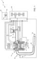
- a vehicle 1 comprises an engine assembly 2.
- the engine assembly comprises an Internal Combustion Engine (ICE) 10 and a controller 100 configured to control the operation of the engine.
- ICE Internal Combustion Engine
- a single cylinder 12 of the engine 10 is depicted.
- the engine may comprise any desirable number of cylinders.
- a piston 14 is provided within the cylinder and configured to reciprocate within the cylinder 12 during a combustion cycle of the engine 10.
- a combustion chamber 12a of the cylinder is defined by one side of the piston 14, the walls of the cylinder 12 and a cylinder head 13.
- the engine assembly 2 comprises an intake system 30 having an air inlet 32 and an intake duct 34. During operation of the engine, air is drawn into the intake system 30 via the inlet 32 and carried to an inlet manifold 18 of the engine by the intake duct 34.
- the intake system further comprises a throttle 36 configured to allow a pressure drop between the inlet 32 and the intake manifold 18 to be selectively varied. The position of the throttle 36 may be controlled by a driver of the vehicle to control the operation of the engine.
- the piston 14 moves within the cylinder 12 to increase the volume of the combustion chamber 12a, drawing air from the inlet manifold 18 into the cylinder via an inlet valve 20.
- the inlet valve 20 is closed and the inlet air within the cylinder 12 is compressed as the piston 14 moves back to reduce the volume of the combustion chamber 12a.
- Fuel is injected into the cylinder via a fuel injector 22 and the air and fuel mixture is ignited by a spark plug 24. Combustion of the air and fuel mixture produces expanding combustion gases that act against the piston 14 to drive a crank shaft 26 of the engine 10.
- combustion gases may be exhausted from the cylinder 12 via an exhaust valve 28 into an exhaust system 50 of the engine assembly 2.
- the exhaust system 50 comprises an exhaust duct 52 configured to carry the exhaust gases from an exhaust manifold 29 of the engine to an exhaust outlet 54, where the exhaust gases are emitted from the vehicle 1.
- the exhaust system further comprises one or more exhaust gas treatment modules 56, such as a catalytic convertor, configured to reduce the quantity of polluting substance in the exhaust gases emitted from the engine 10.
- the intake system 30 may further comprise one or more sensors, such as a pressure sensor 38 and a throttle position sensor 40.
- the sensors may be operatively coupled to the controller 100 and may provide signals to the controller indicating measurements made by the sensors.
- the controller 100 may process the signals in order to determine an appropriate quantity of fuel to be injected into the cylinder 12 and appropriate timings for injecting the fuel and operating the spark plug 24 to ignite the fuel and air mixture within the combustion chamber 12a.
- the position of the throttle 36 may be controlled by the driver in order to control the operation of the engine 10, e.g. to control the amount of torque provided by the engine to drive the vehicle 1.
- the throttle 36 may be coupled, e.g. mechanically coupled, to an accelerator pedal of the vehicle and the driver may control the position of the throttle directly by operating the accelerator pedal.
- the accelerator pedal may be operatively coupled to the controller 100 and may provide a signal to the controller 100 indicating the amount that the pedal is being depressed by the driver. The controller may control the position of the throttle 36 based on the signal from the accelerator pedal in order to control the operation of the engine 10 appropriately.
- the vehicle may comprise a stop-start system configured to shut down the engine 10 automatically when it is not in use and restart the engine automatically when it is required or expected to be required to power the vehicle.
- the stop-start system may be formed by the controller 100, or a module of the controller.
- the controller may be configured to determine when it may be desirable to shut down the engine 10 automatically. For example, when the vehicle is stationary and the driver is not preparing to drive away.
- the controller 100 may control the operation of the fuel injector 22 and/or the spark plug 24 to shut down the engine. Additionally, the controller 100 may be configured to determine when it is desirable to restart the engine, and may control the operation of a starter motor 110 coupled to the crank shaft 26 of the engine to turn over and start the engine.
- the stop-start system may comprise a further controller configured to determine when it may be desirable to shut down and restart the engine 10 automatically.
- the further controller may be communicatively coupled to the controller 100 and may instruct the controller 100 to control the operation of the engine 10 and starter motor 110 accordingly.
- the vehicle 2 further comprises a brake system 60.
- the brake system comprises a brake pedal 62 that may be pressed by the driver in order to operate the brakes to slow and stop the vehicle 2.
- the brake system may be a hydraulic brake system and the force applied by the driver to the brake pedal 62 may determine a pressure of brake fluid within the brake system, and hence, the braking torque applied by the brake system 60 to wheels of the vehicle.
- a brake pedal position sensor 64 may be provided on the brake pedal 62 configured to determine how far the driver is depressing the brake pedal.
- the controller 100 may receive a signal from the brake position sensor 64 and may determine a force being applied to the brake pedal and/or a pressure of the brake fluid within the brake system based on the position of the brake pedal 62.
- the brake system 60 may comprise a pressure sensor and the controller 100 may determine the pressure of brake fluid within the brake system directly from the measurements recorded by the pressure sensor.
- the position of the brake pedal and/or the pressure of brake fluid within the brake system may be a useful input to the controller 100 or the further controller for determining when it may be desirable to shut down and restart the engine 10.
- a threshold value e.g. such that the car is being held stationary by the brake system
- the brake pedal is released, e.g. when the brake pressure is reduced to below a further threshold pressure, it may be desirable to restart the engine.
- the braking pressure required to hold the vehicle stationary may depend on a gradient of the road at the location of the vehicle. Hence, the braking pressure applied by a driver may vary according to the gradient. It may therefore be desirable for the threshold pressure and/or the further threshold pressure to be determined based on the gradient.
- the engine 10 is only shut down when the speed of the vehicle is below a threshold speed.
- the threshold speed may be Om/s. In other words, the engine may only be shut down when the vehicle is stationary. However, in other arrangements, the threshold speed may be greater than Om/s in order to increase the amount of time the engine is stopped.
- the controller 100 or further controller may be configured such that the engine 10 is only shut down once during each stop event, e.g. each time the speed of the vehicle drops below the threshold speed.
- the controller 100 In order to maximise the benefits obtained through shutting down and restarting the engine automatically, it may be desirable to configure the controller 100 such that the engine is shut down as consistently as possible when the vehicle is stopped. Hence, it may be desirable for the threshold pressure to be set as low as possible. However, setting the threshold pressure too low may result in the engine being shut down too often and at times when it is undesirable to the driver. For example, setting the threshold pressure too low may result in the engine shutting down while the driver is moving very slowly or stopped momentarily in traffic. It may therefore be desirable for the threshold pressure to be set sufficiently high that the engine is not shut down when it may be inconvenient or undesirable to the driver. The value of the threshold pressure may therefore be a compromise between maximising the benefits to fuel consumption and emissions, and minimising driver inconvenience.
- the engine it is generally desirable for the engine to be restarted promptly when the driver is preparing to move off from a stopped position.
- the difference between the threshold pressure and the further threshold pressure may be small, such that the engine is restarted as the driver begins to release the brakes.
- the further threshold pressure may therefore be greater than the brake pressure required to hold the vehicle stationary on the incline.
- Driver preference may vary significantly.
- different drivers may have different tolerances to any delays between beginning to release the brake pedal and the engine being restarted to enable them to accelerate away from a stationary position.
- driving styles e.g. driver braking behaviour, may vary significantly between drivers. For example, some drivers may apply a high brake pressure to stop the vehicle and may reduce the brake pressure significantly after the vehicle has come to a stop, whilst other drivers may modulate brake pressure constantly as the vehicle is coming to rest to give a smoother driving experience, and may in some cases increase the brake pressure once the vehicle has stopped. It is therefore challenging to determine values of the threshold pressure and further threshold pressure that are suitable for all drivers.
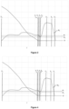
- Figure 2 is a graph showing an example braking behaviour of a driver whilst a vehicle is slowing to a stop.
- brake pressure P b and vehicle speed V are plotted against time T.
- Values of the threshold brake pressure P 1 and further threshold pressure P 2 that are being implemented by a particular controller are also indicated.
- the driver begins to apply the brakes and the speed of the vehicle begins to reduce.
- the brake pressure is modulated by the driver as the vehicle slows and at time T 1 the driver begins to reduce the braking pressure immediately before the vehicle comes to a rest, in order to stop the vehicle smoothly.
- the speed of the vehicle drops below a threshold speed at which the controller may stop the engine automatically.
- the brake pressure is greater than the threshold value, and hence, the controller stops the engine automatically.
- the driver increases the brake pressure in order to hold the vehicle stationary.
- the brake pressure is increased above the threshold value, as the engine has recently been stopped and restarted, the controller does not shut down the engine for a second time.
- the driver may begin to release the brake as the driver prepares to move away and at T 7 the brake pressure may drop below the further threshold pressure.
- the operation of the engine has not been controlled by the controller 100 to maximise the benefits of shutting down and restarting the engine during the stop event.
- the engine of the vehicle has been running undesirably between times T 3 and T 7 .
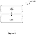
- the controller 100 may be configured to operate the engine using a method 300, in accordance with the present disclosure.
- the method 300 comprises a first step 302, in which the engine 10 is shut down.
- the engine may be shut down when the brake pressure of the brake system is above a threshold pressure and optionally when speed of the vehicle is below a threshold speed.
- the method further comprises a second step 304 in which the further threshold pressure is adjusted, e.g. reduced, according to the speed of the vehicle.
- the further threshold pressure may be reduced when the speed of the vehicle reaches or drops below a further threshold speed.
- the further threshold speed may be Om/s. In other words, the further threshold pressure may be reduced as the vehicle comes to rest. In some arrangements, the further threshold speed may be equal to the threshold speed. Alternatively, the further threshold speed may be less than the threshold speed. For example, the further threshold speed may be Om/s and the threshold speed may be greater than Om/s. In other arrangements, the further threshold speed may be greater than the threshold speed.
- the further threshold pressure may be reduced by a predetermined pressure difference to an adjusted threshold pressure.
- the adjusted threshold pressure may be maintained for a predetermined period of time and following the predetermined period of time the further threshold pressure may be returned to its original, e.g. pre-adjustment, value.
- the further threshold pressure may be greater than a value at which the brake system is able to hold the vehicle stationary on an incline.
- the brake pressure applied by the driver between times T 3 and T 4 may drop below this value, and hence, the adjusted threshold pressure may be less than the value at which the brake system is able to hold the vehicle stationary on an incline.
- the second step 304 may be performed independently of the first step 302.
- the further threshold pressure may be adjusted when the vehicle reaches or drops below the threshold speed regardless of whether the engine has been shut down.
- the further threshold pressure may be adjusted independently of the threshold pressure such that the adjustment does not affect the conditions under which the engine is shut down automatically.
- the second step 304 may be performed only when the engine has been or is about to be shut down.
- the further threshold pressure may be adjusted if the brake pressure is greater than the threshold pressure when the vehicle reaches or drops below the threshold speed.
- Figure 4 illustrates the braking behaviour of the driver slowing the vehicle to a stop in the same manner as shown in Figure 2 . Values of the threshold brake pressure P 1 and further threshold pressure P 2 that are implement by the controller 100 applying the method 300 are also indicated.
- the method 300 prevents the brake pressure dropping below the further threshold pressure at T 3 , and hence, the engine is not restarted undesirably. Furthermore, as the further threshold pressure is returned to its original value after the predetermined period of time, the time between T 6 , when the driver begins to release the brake as the driver prepares to move away, and T 7 , when the brake pressure may drop below the further threshold pressure, is unaffected by the adjustment made to the further threshold pressure. In this way, the controller 100 may compensate for the braking behaviour of the driver without increasing the delay experienced by the driver between beginning to release the brakes and the engine being restarted.
- the length of the predetermined period of time for which the further threshold pressure P 2 is maintained at the adjusted value may determine the amount of time that the driver can reduce the brake pressure as the vehicle comes to a stop without the engine being restarted automatically.
- the predetermined period may be calibrated, e.g. set, during production of the vehicle.
- the predetermine period may be set according to the vehicle in which the controller 100 is installed. For example, the predetermine period may be set according to the size and/or configuration of vehicle and/or the style of driving expected to be performed using the vehicle. In some arrangements, it may be desirable for the driver of the vehicle to adjust the predetermined period to a desired value that suits the driver's driving style.
- the vehicle 1 may comprise a user interface device configured to allow the user to adjust the predetermined period applied by the controller 100. Additionally or alternatively, predetermined period may be adjusted according to a driving mode selected by the driver. The driving mode may be selected using the user interface device or another control provided on the vehicle.
- Using the method 300 to adjust the further threshold pressure may be particularly beneficial when the driver is bringing the vehicle to a smooth stop and is likely to reduce the braking pressure as the vehicle comes to a stop. It may therefore be desirable for the controller to determine a rate of change of speed of the vehicle.
- the controller 100 may adjust the further threshold pressure, e.g. by performing the second step 304 of the method, only if the rate of change of speed of vehicle is below a threshold rate.
Landscapes
- Engineering & Computer Science (AREA)
- Mechanical Engineering (AREA)
- Chemical & Material Sciences (AREA)
- Combustion & Propulsion (AREA)
- General Engineering & Computer Science (AREA)
- Automation & Control Theory (AREA)
- Transportation (AREA)
- Control Of Vehicle Engines Or Engines For Specific Uses (AREA)
- Output Control And Ontrol Of Special Type Engine (AREA)
Claims (9)
- Verfahren zum Betrieb einer Motorbaugruppe (10) eines Kraftfahrzeugs (1), wobei die Baugruppe einen Motor (10) und eine Steuereinheit (100) umfasst, die dazu konfiguriert ist, den Motor (10) automatisch abzuschalten und neu zu starten, wobei das Verfahren die Schritte umfasst:Bestimmen einer Geschwindigkeit (V) des Fahrzeugs und eines Bremsdrucks (Pb) eines Bremssystems (60) des Kraftfahrzeugs (1);Abschalten des Motors (10), wenn der Bremsdruck (Pb) des Bremssystems (60) des Kraftfahrzeugs (1) über einem ersten Schwellenwert (P1) liegt und wenn die Geschwindigkeit (V) des Fahrzeugs unter einer Schwellengeschwindigkeit oder einer weiteren Schwellengeschwindigkeit liegt;Neustarten des Motors (10), wenn der Bremsdruck (Pb) unter einen zweiten Schwellenwert (P2) fällt, wobei der zweite Schwellenwert (P2) zunächst auf einem Vorjustierwert liegt;Bestimmen einer Änderungsrate der Geschwindigkeit des Fahrzeugs (1); undAnpassen des zweiten Schwellenwerts (P2), wenn die Geschwindigkeit (V) des Fahrzeugs (1) unter die Schwellengeschwindigkeit fällt und wenn die Änderungsrate der Geschwindigkeit des Fahrzeugs unter einer Schwellenrate liegt;
undBeibehalten des zweiten Schwellenwerts (P2) andernfalls. - Verfahren nach einem der vorhergehenden Ansprüche, wobei das Verfahren ferner umfasst:
Zurücksetzen des zweiten Schwellenwerts auf den Vorjustierwert nach einem vorbestimmten Zeitraum. - Verfahren nach einem der vorhergehenden Ansprüche, wobei der zweite Schwellenwert unabhängig vom ersten Schwellenwert angepasst wird.
- Motorbaugruppe (2) für ein Kraftfahrzeug (1), wobei die Baugruppe umfasst:einen Motor (10); undeine Steuereinheit (100), die dazu konfiguriert ist die Geschwindigkeit (V) des Fahrzeugs und den Bremsdruck (Pb) eines Bremssystems (60) des Kraftfahrzeugs (1) zu bestimmen;
undden Motor (10) automatisch abzuschalten und neu zu starten,wobei die Steuereinheit dazu konfiguriert ist, den Motor (10) abzuschalten, wenn der Bremsdruck (Pb) des Bremssystems (60) des Kraftfahrzeugs (1) über einem ersten Schwellenwert (P1) liegt und wenn die Geschwindigkeit (V) des Fahrzeugs unter einer Schwellengeschwindigkeit oder einer weiteren Schwellengeschwindigkeit liegt, und den Motor (10) neu zu starten, wenn der Bremsdruck (Pb) unter einen zweiten Schwellenwert (P2) fällt;wobei der zweite Schwellenwert (P2) zunächst auf einem Vorjustierwert liegt;wobei die Steuereinheit (100) ferner dazu konfiguriert ist,eine Änderungsrate der Geschwindigkeit des Fahrzeugs zu bestimmen und den zweiten Schwellenwert (P2) anzupassen, wenn die Geschwindigkeit (V) des Fahrzeugs (1) unter die Schwellengeschwindigkeit fällt und wenn die Änderungsrate der Geschwindigkeit des Fahrzeugs unter einer Schwellenrate liegt;
undwobei die Steuereinheit dazu konfiguriert ist, den zweiten Schwellenwert (P2) andernfalls beizubehalten. - Motorbaugruppe (2) nach Anspruch 4, wobei die Steuereinheit (100) dazu konfiguriert ist, den angepassten Wert des zweiten Schwellenwerts für einen vorbestimmten Zeitraum beizubehalten.
- Motorbaugruppe (2) nach Anspruch 5, wobei die Steuereinheit (100) dazu konfiguriert ist, den vorbestimmten Zeitraum gemäß einer Benutzereingabe anzupassen.
- Motorbaugruppe (2) gemäß einem der Ansprüche 4 bis 6, wobei der zweite Schwellenwert unabhängig vom ersten Schwellenwert angepasst wird.
- Motorbaugruppe (2) gemäß einem der Ansprüche 4 bis 7, wobei der zweite Schwellenwert angepasst wird, wenn der Bremsdruck über dem ersten Schwellenwert liegt.
- Fahrzeug (1), umfassend die Motorbaugruppe (2) nach einem der Ansprüche 4 bis 8.
Applications Claiming Priority (1)
| Application Number | Priority Date | Filing Date | Title |
|---|---|---|---|
| GB1620522.1A GB2557271B (en) | 2016-12-02 | 2016-12-02 | A method of operating an engine assembly |
Publications (2)
| Publication Number | Publication Date |
|---|---|
| EP3333409A1 EP3333409A1 (de) | 2018-06-13 |
| EP3333409B1 true EP3333409B1 (de) | 2025-03-26 |
Family
ID=58159603
Family Applications (1)
| Application Number | Title | Priority Date | Filing Date |
|---|---|---|---|
| EP17201000.1A Active EP3333409B1 (de) | 2016-12-02 | 2017-11-10 | Verfahren zum betrieb einer motoranordnung in einem mit einer start-stopp funktion ausgestatteten fahrzeug |
Country Status (6)
| Country | Link |
|---|---|
| US (1) | US10221822B2 (de) |
| EP (1) | EP3333409B1 (de) |
| CN (1) | CN108150298B (de) |
| GB (1) | GB2557271B (de) |
| MX (1) | MX2017015372A (de) |
| RU (1) | RU2017141729A (de) |
Families Citing this family (3)
| Publication number | Priority date | Publication date | Assignee | Title |
|---|---|---|---|---|
| FR3087843B1 (fr) * | 2018-10-24 | 2020-10-30 | Psa Automobiles Sa | Procede de gestion d'un arret automatique du moteur thermique en fonction d'une activite sur une pedale de frein |
| GB2579178B (en) * | 2018-11-21 | 2021-04-14 | Jaguar Land Rover Ltd | Vehicle control method |
| US11754030B1 (en) * | 2022-07-21 | 2023-09-12 | Hyundai Motor Company | Apparatus and method for optimizing engine restarts |
Family Cites Families (17)
| Publication number | Priority date | Publication date | Assignee | Title |
|---|---|---|---|---|
| JP4374805B2 (ja) * | 2001-07-24 | 2009-12-02 | 株式会社デンソー | エンジン自動車の停止再始動装置 |
| DE102007016987B4 (de) * | 2007-04-10 | 2017-10-12 | Bayerische Motoren Werke Aktiengesellschaft | Verfahren zum selbsttätigen Abschalten und Starten eines Verbrennungsmotors |
| JP2011202845A (ja) * | 2010-03-25 | 2011-10-13 | Panasonic Corp | 空気調和機 |
| JP2011202645A (ja) * | 2010-03-26 | 2011-10-13 | Daihatsu Motor Co Ltd | アイドルストップ制御装置 |
| JP5477137B2 (ja) * | 2010-04-15 | 2014-04-23 | 株式会社デンソー | エンジン自動停止再始動制御装置 |
| JP5652090B2 (ja) * | 2010-09-30 | 2015-01-14 | トヨタ自動車株式会社 | 車両制御装置 |
| JP5834844B2 (ja) * | 2011-11-30 | 2015-12-24 | 日産自動車株式会社 | 車両のエンジン自動制御装置 |
| US9157382B2 (en) * | 2011-12-22 | 2015-10-13 | Toyota Jidosha Kabushiki Kaisha | Idling stop control device, vehicle and vehicle control method |
| JP6011118B2 (ja) * | 2012-07-31 | 2016-10-19 | 株式会社デンソー | エンジン停止始動制御装置 |
| US8998774B2 (en) * | 2012-08-31 | 2015-04-07 | Ford Global Technologies, Llc | Brake apply and release detection for stop/start vehicle |
| US9243600B2 (en) | 2012-09-04 | 2016-01-26 | Ford Global Technologies, Llc | Method and system for improving automatic engine stopping |
| JP5979119B2 (ja) * | 2013-11-13 | 2016-08-24 | トヨタ自動車株式会社 | 車両用制御装置 |
| JP6011518B2 (ja) * | 2013-11-21 | 2016-10-19 | トヨタ自動車株式会社 | 車両用制御装置、制御方法 |
| US9751516B2 (en) | 2014-02-27 | 2017-09-05 | Ford Global Technologies, Llc | Informational based engine stop/start sensitivity control for micro-HEV |
| JP6269564B2 (ja) * | 2015-04-23 | 2018-01-31 | トヨタ自動車株式会社 | アイドリングストップ制御装置 |
| DE102015209972B4 (de) * | 2015-05-29 | 2021-11-25 | Bayerische Motoren Werke Aktiengesellschaft | Start-Stopp-Einrichtung und Verfahren zum Einleiten eines automatischen Abschalt- und/oder Anschaltvorgangs einer Antriebsmaschine |
| JP6711130B2 (ja) * | 2016-05-19 | 2020-06-17 | スズキ株式会社 | 車両のエンジン自動停止再始動装置 |
-
2016
- 2016-12-02 GB GB1620522.1A patent/GB2557271B/en active Active
-
2017
- 2017-11-10 EP EP17201000.1A patent/EP3333409B1/de active Active
- 2017-11-28 CN CN201711218925.3A patent/CN108150298B/zh active Active
- 2017-11-29 MX MX2017015372A patent/MX2017015372A/es unknown
- 2017-11-30 RU RU2017141729A patent/RU2017141729A/ru not_active Application Discontinuation
- 2017-12-01 US US15/828,811 patent/US10221822B2/en active Active
Also Published As
| Publication number | Publication date |
|---|---|
| CN108150298A (zh) | 2018-06-12 |
| GB2557271A (en) | 2018-06-20 |
| RU2017141729A (ru) | 2019-05-31 |
| US20180156178A1 (en) | 2018-06-07 |
| GB2557271B (en) | 2020-03-18 |
| MX2017015372A (es) | 2018-11-09 |
| CN108150298B (zh) | 2022-08-02 |
| EP3333409A1 (de) | 2018-06-13 |
| GB201620522D0 (en) | 2017-01-18 |
| US10221822B2 (en) | 2019-03-05 |
Similar Documents
| Publication | Publication Date | Title |
|---|---|---|
| RU2573189C2 (ru) | Адаптация и определение старта автомобиля | |
| US9050967B1 (en) | Methods and systems for a stop/start engine | |
| US8131454B2 (en) | Method for starting an internal combustion engine | |
| CN109466539B (zh) | 用于调整请求的车辆扭矩的方法 | |
| RU2731647C9 (ru) | Способ (варианты) и система управления муфтой сцепления трансмиссии автомобиля с ручным переключением | |
| CN105313670A (zh) | 用于应用传动系分离离合器的方法和系统 | |
| CN101539060B (zh) | 滑行事件期间的发动机控制 | |
| EP3333409B1 (de) | Verfahren zum betrieb einer motoranordnung in einem mit einer start-stopp funktion ausgestatteten fahrzeug | |
| CN109072998B (zh) | 车辆控制装置 | |
| EP2295773B1 (de) | Steuerungsverfahren, Computerprogrammprodukt, Steuerungsvorrichtung für Motor und Motor | |
| CN103032187A (zh) | 用于运行内燃机的方法 | |
| EP2966285A1 (de) | Fahrzeugsteuerungsvorrichtung und fahrzeugsteuerungsverfahren | |
| JP2012144184A (ja) | 車両制御装置 | |
| CN108979877B (zh) | 用于包括压缩机的发动机的瞬时动力控制方法 | |
| JP4799654B2 (ja) | 内燃機関の発電制御装置 | |
| JP2014240206A (ja) | 車両の制御装置および制御方法 | |
| JP6595091B2 (ja) | 車両用制御装置 | |
| CN106627563B (zh) | 用于在滚动车辆的发动机停止和启动期间使变速器运转的系统和方法 | |
| JP6594796B2 (ja) | 車両用制御装置 | |
| RU2614522C2 (ru) | Способ управления двигателем и система двигателя | |
| US11098688B2 (en) | System and methods for starting an engine | |
| US9272698B2 (en) | Stopping a hybrid engine with engine start anticipation | |
| CN105190024B (zh) | 伴随喷射中断的减速时的内燃机转矩管理方法和相应车辆 | |
| JP2014136530A (ja) | 制御装置 | |
| RU2735193C2 (ru) | Способ управления мотором транспортного средства и устройство управления двигателем и мотором транспортного средства |
Legal Events
| Date | Code | Title | Description |
|---|---|---|---|
| PUAI | Public reference made under article 153(3) epc to a published international application that has entered the european phase |
Free format text: ORIGINAL CODE: 0009012 |
|
| STAA | Information on the status of an ep patent application or granted ep patent |
Free format text: STATUS: THE APPLICATION HAS BEEN PUBLISHED |
|
| AK | Designated contracting states |
Kind code of ref document: A1 Designated state(s): AL AT BE BG CH CY CZ DE DK EE ES FI FR GB GR HR HU IE IS IT LI LT LU LV MC MK MT NL NO PL PT RO RS SE SI SK SM TR |
|
| AX | Request for extension of the european patent |
Extension state: BA ME |
|
| STAA | Information on the status of an ep patent application or granted ep patent |
Free format text: STATUS: REQUEST FOR EXAMINATION WAS MADE |
|
| 17P | Request for examination filed |
Effective date: 20180702 |
|
| RBV | Designated contracting states (corrected) |
Designated state(s): AL AT BE BG CH CY CZ DE DK EE ES FI FR GB GR HR HU IE IS IT LI LT LU LV MC MK MT NL NO PL PT RO RS SE SI SK SM TR |
|
| STAA | Information on the status of an ep patent application or granted ep patent |
Free format text: STATUS: EXAMINATION IS IN PROGRESS |
|
| 17Q | First examination report despatched |
Effective date: 20210510 |
|
| P01 | Opt-out of the competence of the unified patent court (upc) registered |
Effective date: 20230620 |
|
| GRAP | Despatch of communication of intention to grant a patent |
Free format text: ORIGINAL CODE: EPIDOSNIGR1 |
|
| STAA | Information on the status of an ep patent application or granted ep patent |
Free format text: STATUS: GRANT OF PATENT IS INTENDED |
|
| INTG | Intention to grant announced |
Effective date: 20241209 |
|
| GRAS | Grant fee paid |
Free format text: ORIGINAL CODE: EPIDOSNIGR3 |
|
| GRAA | (expected) grant |
Free format text: ORIGINAL CODE: 0009210 |
|
| STAA | Information on the status of an ep patent application or granted ep patent |
Free format text: STATUS: THE PATENT HAS BEEN GRANTED |
|
| AK | Designated contracting states |
Kind code of ref document: B1 Designated state(s): AL AT BE BG CH CY CZ DE DK EE ES FI FR GB GR HR HU IE IS IT LI LT LU LV MC MK MT NL NO PL PT RO RS SE SI SK SM TR |
|
| REG | Reference to a national code |
Ref country code: GB Ref legal event code: FG4D Ref country code: DE Ref legal event code: R084 Ref document number: 602017088512 Country of ref document: DE |
|
| REG | Reference to a national code |
Ref country code: CH Ref legal event code: EP |
|
| REG | Reference to a national code |
Ref country code: DE Ref legal event code: R096 Ref document number: 602017088512 Country of ref document: DE |
|
| REG | Reference to a national code |
Ref country code: IE Ref legal event code: FG4D |
|
| PG25 | Lapsed in a contracting state [announced via postgrant information from national office to epo] |
Ref country code: RS Free format text: LAPSE BECAUSE OF FAILURE TO SUBMIT A TRANSLATION OF THE DESCRIPTION OR TO PAY THE FEE WITHIN THE PRESCRIBED TIME-LIMIT Effective date: 20250626 |
|
| PG25 | Lapsed in a contracting state [announced via postgrant information from national office to epo] |
Ref country code: FI Free format text: LAPSE BECAUSE OF FAILURE TO SUBMIT A TRANSLATION OF THE DESCRIPTION OR TO PAY THE FEE WITHIN THE PRESCRIBED TIME-LIMIT Effective date: 20250326 |
|
| REG | Reference to a national code |
Ref country code: LT Ref legal event code: MG9D |
|
| PG25 | Lapsed in a contracting state [announced via postgrant information from national office to epo] |
Ref country code: NO Free format text: LAPSE BECAUSE OF FAILURE TO SUBMIT A TRANSLATION OF THE DESCRIPTION OR TO PAY THE FEE WITHIN THE PRESCRIBED TIME-LIMIT Effective date: 20250626 |
|
| PG25 | Lapsed in a contracting state [announced via postgrant information from national office to epo] |
Ref country code: HR Free format text: LAPSE BECAUSE OF FAILURE TO SUBMIT A TRANSLATION OF THE DESCRIPTION OR TO PAY THE FEE WITHIN THE PRESCRIBED TIME-LIMIT Effective date: 20250326 |
|
| PG25 | Lapsed in a contracting state [announced via postgrant information from national office to epo] |
Ref country code: LV Free format text: LAPSE BECAUSE OF FAILURE TO SUBMIT A TRANSLATION OF THE DESCRIPTION OR TO PAY THE FEE WITHIN THE PRESCRIBED TIME-LIMIT Effective date: 20250326 |
|
| PG25 | Lapsed in a contracting state [announced via postgrant information from national office to epo] |
Ref country code: GR Free format text: LAPSE BECAUSE OF FAILURE TO SUBMIT A TRANSLATION OF THE DESCRIPTION OR TO PAY THE FEE WITHIN THE PRESCRIBED TIME-LIMIT Effective date: 20250627 Ref country code: BG Free format text: LAPSE BECAUSE OF FAILURE TO SUBMIT A TRANSLATION OF THE DESCRIPTION OR TO PAY THE FEE WITHIN THE PRESCRIBED TIME-LIMIT Effective date: 20250326 |
|
| REG | Reference to a national code |
Ref country code: NL Ref legal event code: MP Effective date: 20250326 |
|
| PG25 | Lapsed in a contracting state [announced via postgrant information from national office to epo] |
Ref country code: NL Free format text: LAPSE BECAUSE OF FAILURE TO SUBMIT A TRANSLATION OF THE DESCRIPTION OR TO PAY THE FEE WITHIN THE PRESCRIBED TIME-LIMIT Effective date: 20250326 |
|
| PG25 | Lapsed in a contracting state [announced via postgrant information from national office to epo] |
Ref country code: SE Free format text: LAPSE BECAUSE OF FAILURE TO SUBMIT A TRANSLATION OF THE DESCRIPTION OR TO PAY THE FEE WITHIN THE PRESCRIBED TIME-LIMIT Effective date: 20250326 |
|
| REG | Reference to a national code |
Ref country code: AT Ref legal event code: MK05 Ref document number: 1779195 Country of ref document: AT Kind code of ref document: T Effective date: 20250326 |
|
| PG25 | Lapsed in a contracting state [announced via postgrant information from national office to epo] |
Ref country code: SM Free format text: LAPSE BECAUSE OF FAILURE TO SUBMIT A TRANSLATION OF THE DESCRIPTION OR TO PAY THE FEE WITHIN THE PRESCRIBED TIME-LIMIT Effective date: 20250326 |
|
| PG25 | Lapsed in a contracting state [announced via postgrant information from national office to epo] |
Ref country code: PT Free format text: LAPSE BECAUSE OF FAILURE TO SUBMIT A TRANSLATION OF THE DESCRIPTION OR TO PAY THE FEE WITHIN THE PRESCRIBED TIME-LIMIT Effective date: 20250728 Ref country code: ES Free format text: LAPSE BECAUSE OF FAILURE TO SUBMIT A TRANSLATION OF THE DESCRIPTION OR TO PAY THE FEE WITHIN THE PRESCRIBED TIME-LIMIT Effective date: 20250326 |
|
| PG25 | Lapsed in a contracting state [announced via postgrant information from national office to epo] |
Ref country code: PL Free format text: LAPSE BECAUSE OF FAILURE TO SUBMIT A TRANSLATION OF THE DESCRIPTION OR TO PAY THE FEE WITHIN THE PRESCRIBED TIME-LIMIT Effective date: 20250326 Ref country code: IT Free format text: LAPSE BECAUSE OF FAILURE TO SUBMIT A TRANSLATION OF THE DESCRIPTION OR TO PAY THE FEE WITHIN THE PRESCRIBED TIME-LIMIT Effective date: 20250326 |
|
| PG25 | Lapsed in a contracting state [announced via postgrant information from national office to epo] |
Ref country code: AT Free format text: LAPSE BECAUSE OF FAILURE TO SUBMIT A TRANSLATION OF THE DESCRIPTION OR TO PAY THE FEE WITHIN THE PRESCRIBED TIME-LIMIT Effective date: 20250326 |
|
| PG25 | Lapsed in a contracting state [announced via postgrant information from national office to epo] |
Ref country code: EE Free format text: LAPSE BECAUSE OF FAILURE TO SUBMIT A TRANSLATION OF THE DESCRIPTION OR TO PAY THE FEE WITHIN THE PRESCRIBED TIME-LIMIT Effective date: 20250326 |
|
| PG25 | Lapsed in a contracting state [announced via postgrant information from national office to epo] |
Ref country code: RO Free format text: LAPSE BECAUSE OF FAILURE TO SUBMIT A TRANSLATION OF THE DESCRIPTION OR TO PAY THE FEE WITHIN THE PRESCRIBED TIME-LIMIT Effective date: 20250326 |
|
| PG25 | Lapsed in a contracting state [announced via postgrant information from national office to epo] |
Ref country code: SK Free format text: LAPSE BECAUSE OF FAILURE TO SUBMIT A TRANSLATION OF THE DESCRIPTION OR TO PAY THE FEE WITHIN THE PRESCRIBED TIME-LIMIT Effective date: 20250326 |
|
| PG25 | Lapsed in a contracting state [announced via postgrant information from national office to epo] |
Ref country code: IS Free format text: LAPSE BECAUSE OF FAILURE TO SUBMIT A TRANSLATION OF THE DESCRIPTION OR TO PAY THE FEE WITHIN THE PRESCRIBED TIME-LIMIT Effective date: 20250726 |
|
| REG | Reference to a national code |
Ref country code: DE Ref legal event code: R097 Ref document number: 602017088512 Country of ref document: DE |
|
| PGFP | Annual fee paid to national office [announced via postgrant information from national office to epo] |
Ref country code: DE Payment date: 20251013 Year of fee payment: 9 |
|
| PG25 | Lapsed in a contracting state [announced via postgrant information from national office to epo] |
Ref country code: DK Free format text: LAPSE BECAUSE OF FAILURE TO SUBMIT A TRANSLATION OF THE DESCRIPTION OR TO PAY THE FEE WITHIN THE PRESCRIBED TIME-LIMIT Effective date: 20250326 |
|
| PG25 | Lapsed in a contracting state [announced via postgrant information from national office to epo] |
Ref country code: CZ Free format text: LAPSE BECAUSE OF FAILURE TO SUBMIT A TRANSLATION OF THE DESCRIPTION OR TO PAY THE FEE WITHIN THE PRESCRIBED TIME-LIMIT Effective date: 20250326 |
|
| PLBE | No opposition filed within time limit |
Free format text: ORIGINAL CODE: 0009261 |
|
| STAA | Information on the status of an ep patent application or granted ep patent |
Free format text: STATUS: NO OPPOSITION FILED WITHIN TIME LIMIT |
|
| REG | Reference to a national code |
Ref country code: CH Ref legal event code: L10 Free format text: ST27 STATUS EVENT CODE: U-0-0-L10-L00 (AS PROVIDED BY THE NATIONAL OFFICE) Effective date: 20260211 |
|
| 26N | No opposition filed |
Effective date: 20260105 |