EP3333111A1 - Handlaufreibungsüberprüfungsvorrichtung - Google Patents
Handlaufreibungsüberprüfungsvorrichtung Download PDFInfo
- Publication number
- EP3333111A1 EP3333111A1 EP17204921.5A EP17204921A EP3333111A1 EP 3333111 A1 EP3333111 A1 EP 3333111A1 EP 17204921 A EP17204921 A EP 17204921A EP 3333111 A1 EP3333111 A1 EP 3333111A1
- Authority
- EP
- European Patent Office
- Prior art keywords
- handrail
- checking device
- gripper
- spring
- friction
- Prior art date
- Legal status (The legal status is an assumption and is not a legal conclusion. Google has not performed a legal analysis and makes no representation as to the accuracy of the status listed.)
- Granted
Links
Images



Classifications
-
- G—PHYSICS
- G01—MEASURING; TESTING
- G01N—INVESTIGATING OR ANALYSING MATERIALS BY DETERMINING THEIR CHEMICAL OR PHYSICAL PROPERTIES
- G01N19/00—Investigating materials by mechanical methods
- G01N19/02—Measuring coefficient of friction between materials
-
- B—PERFORMING OPERATIONS; TRANSPORTING
- B66—HOISTING; LIFTING; HAULING
- B66B—ELEVATORS; ESCALATORS OR MOVING WALKWAYS
- B66B27/00—Indicating operating conditions of escalators or moving walkways
-
- B—PERFORMING OPERATIONS; TRANSPORTING
- B66—HOISTING; LIFTING; HAULING
- B66B—ELEVATORS; ESCALATORS OR MOVING WALKWAYS
- B66B25/00—Control of escalators or moving walkways
- B66B25/006—Monitoring for maintenance or repair
-
- B—PERFORMING OPERATIONS; TRANSPORTING
- B66—HOISTING; LIFTING; HAULING
- B66B—ELEVATORS; ESCALATORS OR MOVING WALKWAYS
- B66B31/00—Accessories for escalators, or moving walkways, e.g. for sterilising or cleaning
- B66B31/02—Accessories for escalators, or moving walkways, e.g. for sterilising or cleaning for handrails
Definitions
- This invention generally relates to passenger conveyors. More particularly, this invention relates to a device for checking the frictional driving force for a handrail of a passenger conveyor.
- Passenger conveyors have proven effective for carrying people between different levels within a building or across an elongated pathway, for example.
- Typical arrangements include a plurality of steps or a belt upon which an individual stands to be carried from one location to another.
- a handrail typically rides over a balustrade and provides a surface for an individual to grab onto for stabilizing themselves.
- Handrails are driven to move in unison with the steps or moving belt.
- a handrail drive mechanism causes the desired movement of the handrail.
- Typical arrangements rely upon wheels or rollers that frictionally engage the handrail to generate enough friction to drive the handrail in the desired direction.
- a fabric layer is provided on the side of the handrail opposite the side grabbed by an individual to allow the handrail to readily slide along a guide to follow the balustrade.
- the same surface is frictionally engaged by the handrail drive mechanism. The friction caused by the wheels or rollers in the handrail drive mechanism tends to wear the fabric layer. As this fabric layer becomes worn, the handrail eventually can not operate as desired and requires repair or replacement.
- misalignment or displacement of the wheels or rollers in the handrail drive mechanism may also affect the frictional driving force of the handrail. Therefore, it is necessary to check on a regular basis if there is a sufficient frictional force for driving the handrail.
- a handrail friction checking device comprises a handrail gripper for gripping the handrail and movable together with the handrail, a spring with one end of the spring being fixed and the other end being connected to the handrail gripper so that the spring can apply a spring force which is opposed to the direction of handrail movement to the handrail gripper when the handrail gripper moves along with the handrail and a sensor which is disposed in a way that it is distanced from the handrail gripper and can be triggered by the handrail gripper when the handrail gripper moves along with the handrail.
- the handrail friction checking device may further comprise a base fixed to a structural component and connected to one end of the spring, an intermediate member connected to the other end of the spring and a connecting member connecting the intermediate member to the handrail gripper.
- Fig. 1 schematically shows a passenger conveyer 1.
- the passenger conveyor 1 is an escalator having a plurality of steps for carrying passengers between landings at different levels within a building.
- This invention is not limited to escalators but is also applicable to other forms of passenger conveyors 1 such as moving walkways, for example.
- the example passenger conveyor 1 of Fig. 1 comprises a truss 4 installed between a lower landing 2 and an upper landing 3.
- An escalator drive device 5 is located in the upper end of the truss 4 and is connected via a chain 6 to a sprocket wheel 7 of a step chain drive mechanism which drives a plurality of steps along a closed loop.
- the sprocket wheel 7 is in turn connected via a chain 8 to a friction wheel 9 of a handrail drive mechanism to transfer a driving force thereto.
- the friction wheel 9 drives a handrail 10 along a closed loop by frictional engagement with the inside surface thereof, i.e., the surface opposite the surface grasped by a passenger.
- a handrail friction checking device 12 of the present invention is positioned in the return path of the handrail 10.
- One handrail friction checking device 12 may be provided for each handrail 10.
- the handrail 10 may be of the conventional flexible construction having a C-shaped cross section as shown in figure 4 .
- a conventional T-shaped handrail guide 11 is located within the cross section of the handrail 10 to serve as a guide means. In the return path of the handrail 10, the handrail guide 11 is supported on a structural component 13 of the truss 4.
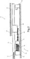
- the handrail friction checking device 12 is positioned just below the handrail 10 and comprises a load applying device 14 and a sensor 15.
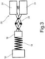
- the load applying device 14 comprises a base 16, a coil spring 18 connected between the base 16 and an intermediate member 19, a handrail gripper 20 for gripping the handrail 10 and a connecting member 22 which connects the handrail gripper 20 to the intermediate member 19.
- the sensor 15 comprises a limit switch in this embodiment but may be any kind of sensor which is able to detect movement of the handrail gripper 20 such as a proximity sensor.
- the base 16 and the sensor 15 are fixed on a structural component 23 of the truss 4.
- the intermediate member 19 and handrail gripper 20 are guided to slide in the longitudinal direction in parallel with the handrail 10 such as by a sliding mechanism (not shown) which may include a guide rail and a sliding element.
- the connecting member 22 is a pantograph.
- the handrail gripper 20 comprises a pair of gripping elements 24 each having an inner surface 24a shaped complementary to one side of the outer surface of the handrail 10, i.e., the surface grasped by a passenger.
- the gripping elements 24 are slidable in the lateral direction with respect to one another by a conventional means and biased by a spring 25 in a direction away from each other.
- At least one of the gripping elements 24 comprises an electromagnet 26 and the other of the gripping elements comprises an iron portion.
- the gripping elements 24 are biased in a direction away from each other and away from the handrail 10 by the spring 25, as shown in figure 5(a) .
- the gripping elements 24 are attracted toward each other to firmly grip the outer surface of the handrail 10, as shown in figure 5(b) .
- a slip stopper 27 such as a rubber element may be provided on the inner surface 24a of each of the gripping elements 24 to allow a firm grip of the gripping elements 24 on the handrail 10.
- Figure 6 shows how the handrail friction checking device 12 operates.
- the handrail friction checking device 12 is not operating, i.e., the handrail gripper 20 is not energized, the handrail 10 is allowed to freely move through the gripping elements 24, as shown in figure 6(a) .
- the limit switch 15 is in an OFF state.
- the handrail gripper 20 When a test using the handrail friction checking device 12 is started, the handrail gripper 20 is energized to firmly grip the handrail 10 such that the handrail gripper 20 travels with the handrail 10, as shown in figure 6(b) . As the handrail gripper 20 moves toward the limit switch 15, the coil spring 18 extends to apply a spring force on the handrail 10. In figure 6(c) , the handrail gripper 20 has reached the limit switch 15 and has turned the limit switch 15 ON. In this position, a spring force F 1 is applied on the handrail 10 which is proportional to the distance the coil spring 18 has extended.
- the fact that the limit switch 15 is switched ON indicates that the frictional driving force F 2 of the handrail is sufficiently large. Specifically, it indicates that the frictional driving force F 2 of the handrail is larger than the spring force F 1 plus the traveling resistance between the handrail 10 and the handrail guide 11.
- the limit switch 15 is not switched ON, it indicates that the frictional driving force F 2 of the handrail is not sufficient. Specifically, it indicates that the frictional driving force F 2 of the handrail is insufficient such that slippage between the friction wheel 9 and handrail 10 occurs, preventing the handrail gripper 20 to reach the limit switch 15.
- FIG. 7 is a flowchart showing a control sequence of a test conducted using the handrail friction checking device 12 of the present invention.
- the test is started at step 1 and the handrail gripper 20 is subsequently energized at step 2.
- step 3 it is checked if the limit switch 15 is ON after a predetermined time delay. If “No”, it is determined that the frictional driving force F 2 is not sufficient at step 4. If “Yes”, it is determined that there is a sufficient frictional driving force F 2 at step 5. From steps 4 and 5 the sequence proceeds to step 6 at which the handrail gripper 20 is de-energized. Then, the determination made in step 4 or 5 is sent to a remote control center or a mobile device of a service engineer at step 7 and the test ends at step 8.
- the test may be performed remotely from the remote control center during times of day the passenger conveyor 1 is not operating such as midnight.
- the test may also be performed at the site via a mobile device carried by a service engineer.
- Figure 8 shows how the pantograph 22 contributes to further clamp the handrail 10 when the handrail gripper 20 grips the handrail 10.
- Figure 8(a) shows the load applying device 14 with the handrail gripper 20 in a de-energized state.
- the handrail gripper 20 is energized to firmly grip the handrail 10.
- the pantograph 22 elongates such that a component force F 3 develops on the inner surface 24a of the gripping elements 24.
- the component force F 3 acts to further clamp the handrail 10 between the gripping elements 24.
- FIG 9 shows another embodiment of the load applying device 14 in which the gripping elements 28 each have an inclined outer surface 28b and the connecting member 22 is a pair of plates 29.
- Each of the plates 29 are attached to an inclined outer surface 28b of a respective gripping element 28 at one end and are pivotally connected to the intermediate member 19 via a pin 19a at the other end.
- the plates 29 are inclined with respect to a center line CL.
- a component force F 3 develops on the inner surface of the gripping elements 28 to further clamp the handrail 10 between the gripping elements 28.
- the spring force F 1 may be adjustable.
- the base 16 may comprise a bolt 30 and a mounting member 31 attached to a structural component 23 of the truss 4.
- the bolt 30 is rotatable within the mounting member 31 and is screwed into a nut 32 to which the coil spring 18 is connected. By rotating the bolt 30, the distance between the coil spring 18 and the limit switch 15 may be changed to adjust the spring force F 1 .
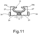
- the lateral gap G between the gripping elements 24 may also be adjusted.
- the gap G may be adjusted by bolts 34. Since the handrail 10 must slide along the handrail guide 11 during testing, the gripping force of the gripping elements 24 should not be too strong such that the gripping elements 24 clamp the handrail 10 against the handrail guide 11.
- the gripping force of the handrail gripper 20 may be adjusted such that the handrail 10 is firmly gripped but slides along the handrail guide 11 during testing.
Landscapes
- Engineering & Computer Science (AREA)
- Automation & Control Theory (AREA)
- Physics & Mathematics (AREA)
- Health & Medical Sciences (AREA)
- Life Sciences & Earth Sciences (AREA)
- Chemical & Material Sciences (AREA)
- Analytical Chemistry (AREA)
- Biochemistry (AREA)
- General Health & Medical Sciences (AREA)
- General Physics & Mathematics (AREA)
- Immunology (AREA)
- Pathology (AREA)
- Escalators And Moving Walkways (AREA)
Applications Claiming Priority (1)
| Application Number | Priority Date | Filing Date | Title |
|---|---|---|---|
| US15/371,487 US10302549B2 (en) | 2016-12-07 | 2016-12-07 | Handrail friction checking device |
Publications (2)
| Publication Number | Publication Date |
|---|---|
| EP3333111A1 true EP3333111A1 (de) | 2018-06-13 |
| EP3333111B1 EP3333111B1 (de) | 2019-10-16 |
Family
ID=60543462
Family Applications (1)
| Application Number | Title | Priority Date | Filing Date |
|---|---|---|---|
| EP17204921.5A Active EP3333111B1 (de) | 2016-12-07 | 2017-12-01 | Handlaufreibungsüberprüfungsvorrichtung |
Country Status (4)
| Country | Link |
|---|---|
| US (1) | US10302549B2 (de) |
| EP (1) | EP3333111B1 (de) |
| JP (1) | JP6981863B2 (de) |
| CN (1) | CN108163689B (de) |
Families Citing this family (2)
| Publication number | Priority date | Publication date | Assignee | Title |
|---|---|---|---|---|
| US11435244B2 (en) * | 2017-11-30 | 2022-09-06 | Koc Universitesi | Force sensor for measuring static and dynamic friction coefficients |
| US10850948B2 (en) * | 2018-09-12 | 2020-12-01 | Otis Elevator Company | Escalator with a sensor for detecting sheave misalignment |
Citations (4)
| Publication number | Priority date | Publication date | Assignee | Title |
|---|---|---|---|---|
| JPS5855831A (ja) * | 1981-09-30 | 1983-04-02 | Hitachi Ltd | マイコンベアのハンドレ−ルの走行力測定器 |
| JP2004224553A (ja) * | 2003-01-27 | 2004-08-12 | Mitsubishi Electric Corp | 乗客コンベアの手摺侵入口安全装置 |
| JP2006182534A (ja) * | 2004-12-28 | 2006-07-13 | Mitsubishi Electric Building Techno Service Co Ltd | エスカレーターの移動手摺監視装置 |
| JP2013184792A (ja) * | 2012-03-08 | 2013-09-19 | Toshiba Elevator Co Ltd | 乗客コンベアの移動手摺引張力測定治具 |
Family Cites Families (20)
| Publication number | Priority date | Publication date | Assignee | Title |
|---|---|---|---|---|
| US4134883A (en) | 1977-08-23 | 1979-01-16 | Westinghouse Electric Corp. | Abrasion resistant polyurethane article having a high rolling coefficient of friction |
| JPS61145096A (ja) * | 1984-12-19 | 1986-07-02 | 日立エレベ−タ−サ−ビス株式会社 | マンコンベアのハンドレ−ルの走行力測定器 |
| JPS6246707Y2 (de) * | 1985-03-29 | 1987-12-18 | ||
| JPH0699107B2 (ja) | 1989-12-19 | 1994-12-07 | 三菱電機株式会社 | エスカレーターの安全装置 |
| US5092446A (en) | 1991-06-13 | 1992-03-03 | Ecs Corporation | Handrail monitoring system |
| JPH0570077A (ja) | 1991-09-11 | 1993-03-23 | Hitachi Building Syst Eng & Service Co Ltd | 乗客コンベアの移動手摺り速度検出装置 |
| JPH05105383A (ja) | 1991-10-21 | 1993-04-27 | Mitsubishi Electric Corp | マンコンベアの手摺装置 |
| US5563392A (en) * | 1995-04-12 | 1996-10-08 | Patco Sales & Service, Inc. | Method and apparatus for monitoring wear of a continuous chain |
| JPH09272687A (ja) | 1996-04-02 | 1997-10-21 | Central Japan Railway Co | エスカレータの手摺ベルトスリップ監視システム |
| DE19723897A1 (de) * | 1997-06-05 | 1998-12-10 | O & K Rolltreppen Gmbh | Sicherheitseinrichtung für Personenförderanlagen |
| JP2001302164A (ja) | 2000-04-26 | 2001-10-31 | Mitsubishi Electric Building Techno Service Co Ltd | エスカレータの移動手摺り駆動装置 |
| DE10141412C2 (de) | 2001-08-23 | 2003-12-04 | Kone Corp | Verfahren und Einrichtung zur Geschwindigkeitsüberwachung sich bewegender Bauteile von Personenförderanlagen |
| CA2528073A1 (en) | 2003-06-04 | 2004-12-16 | Semperit Aktiengesellschaft Holding | Handrail, handrail guiding system, and handrail drive system of an escalator or moving sidewalk |
| JP4391926B2 (ja) | 2004-12-01 | 2009-12-24 | 三菱電機ビルテクノサービス株式会社 | 手摺駆動装置、手摺走行抵抗値算出装置、監視装置 |
| JP2006306607A (ja) | 2005-05-02 | 2006-11-09 | Hitachi Building Systems Co Ltd | 移動手摺りの走行抵抗測定方法及び装置 |
| JP2008037601A (ja) | 2006-08-08 | 2008-02-21 | Hitachi Building Systems Co Ltd | 移動手摺の滑り検知方法およびこの方法を採用した移動手摺の滑り検知装置 |
| JP2008265941A (ja) | 2007-04-19 | 2008-11-06 | Hitachi Building Systems Co Ltd | 移動手摺りの帆布面用摩擦係数低下検出装置 |
| JP2008265971A (ja) | 2007-04-23 | 2008-11-06 | Toshiba Elevator Co Ltd | エスカレータブレーキスリップ距離測定装置およびその測定方法 |
| US8061215B2 (en) * | 2008-06-13 | 2011-11-22 | Ehc Canada, Inc. | Apparatus for and method of measuring tension in a handrail for an escalator or moving walkway |
| JP4607988B2 (ja) | 2008-06-24 | 2011-01-05 | 株式会社日立ビルシステム | 乗客コンベアのハンドレール駆動力監視装置 |
-
2016
- 2016-12-07 US US15/371,487 patent/US10302549B2/en active Active
-
2017
- 2017-12-01 EP EP17204921.5A patent/EP3333111B1/de active Active
- 2017-12-06 CN CN201711277092.8A patent/CN108163689B/zh active Active
- 2017-12-07 JP JP2017234757A patent/JP6981863B2/ja not_active Expired - Fee Related
Patent Citations (4)
| Publication number | Priority date | Publication date | Assignee | Title |
|---|---|---|---|---|
| JPS5855831A (ja) * | 1981-09-30 | 1983-04-02 | Hitachi Ltd | マイコンベアのハンドレ−ルの走行力測定器 |
| JP2004224553A (ja) * | 2003-01-27 | 2004-08-12 | Mitsubishi Electric Corp | 乗客コンベアの手摺侵入口安全装置 |
| JP2006182534A (ja) * | 2004-12-28 | 2006-07-13 | Mitsubishi Electric Building Techno Service Co Ltd | エスカレーターの移動手摺監視装置 |
| JP2013184792A (ja) * | 2012-03-08 | 2013-09-19 | Toshiba Elevator Co Ltd | 乗客コンベアの移動手摺引張力測定治具 |
Also Published As
| Publication number | Publication date |
|---|---|
| JP2018095479A (ja) | 2018-06-21 |
| US20180156714A1 (en) | 2018-06-07 |
| EP3333111B1 (de) | 2019-10-16 |
| US10302549B2 (en) | 2019-05-28 |
| JP6981863B2 (ja) | 2021-12-17 |
| CN108163689B (zh) | 2020-12-15 |
| CN108163689A (zh) | 2018-06-15 |
Similar Documents
| Publication | Publication Date | Title |
|---|---|---|
| US7954620B2 (en) | Passenger conveyor handrail drive control strategy | |
| EP3333111A1 (de) | Handlaufreibungsüberprüfungsvorrichtung | |
| JP4672656B2 (ja) | エレベータの安全装置 | |
| CN104271488B (zh) | 用于乘客输送机的制动系统 | |
| CN101258093B (zh) | 步道和控制步道操作的方法 | |
| CN100384712C (zh) | 自动调整自动扶梯扶手的系统及方法 | |
| EP2809605B1 (de) | Hilfsbremsen für personenförderanlagen | |
| JP2017019591A (ja) | 手摺りベルト及びそれを用いた乗客コンベア | |
| JP6580275B2 (ja) | エレベータのインターロック装置 | |
| HK1137723B (en) | Passenger conveyor handrail drive device | |
| HK1136809B (en) | Passenger conveyor handrail drive control strategy | |
| HK1076793B (en) | Automatically adjusting escalator handrail system and method | |
| HK1170714B (en) | A passenger conveyor and a main drive shaft brake and a method of controlling the brake |
Legal Events
| Date | Code | Title | Description |
|---|---|---|---|
| PUAI | Public reference made under article 153(3) epc to a published international application that has entered the european phase |
Free format text: ORIGINAL CODE: 0009012 |
|
| STAA | Information on the status of an ep patent application or granted ep patent |
Free format text: STATUS: THE APPLICATION HAS BEEN PUBLISHED |
|
| AK | Designated contracting states |
Kind code of ref document: A1 Designated state(s): AL AT BE BG CH CY CZ DE DK EE ES FI FR GB GR HR HU IE IS IT LI LT LU LV MC MK MT NL NO PL PT RO RS SE SI SK SM TR |
|
| AX | Request for extension of the european patent |
Extension state: BA ME |
|
| STAA | Information on the status of an ep patent application or granted ep patent |
Free format text: STATUS: REQUEST FOR EXAMINATION WAS MADE |
|
| 17P | Request for examination filed |
Effective date: 20181204 |
|
| RBV | Designated contracting states (corrected) |
Designated state(s): AL AT BE BG CH CY CZ DE DK EE ES FI FR GB GR HR HU IE IS IT LI LT LU LV MC MK MT NL NO PL PT RO RS SE SI SK SM TR |
|
| GRAP | Despatch of communication of intention to grant a patent |
Free format text: ORIGINAL CODE: EPIDOSNIGR1 |
|
| STAA | Information on the status of an ep patent application or granted ep patent |
Free format text: STATUS: GRANT OF PATENT IS INTENDED |
|
| INTG | Intention to grant announced |
Effective date: 20190513 |
|
| GRAS | Grant fee paid |
Free format text: ORIGINAL CODE: EPIDOSNIGR3 |
|
| GRAA | (expected) grant |
Free format text: ORIGINAL CODE: 0009210 |
|
| STAA | Information on the status of an ep patent application or granted ep patent |
Free format text: STATUS: THE PATENT HAS BEEN GRANTED |
|
| AK | Designated contracting states |
Kind code of ref document: B1 Designated state(s): AL AT BE BG CH CY CZ DE DK EE ES FI FR GB GR HR HU IE IS IT LI LT LU LV MC MK MT NL NO PL PT RO RS SE SI SK SM TR |
|
| REG | Reference to a national code |
Ref country code: GB Ref legal event code: FG4D |
|
| REG | Reference to a national code |
Ref country code: CH Ref legal event code: EP |
|
| REG | Reference to a national code |
Ref country code: DE Ref legal event code: R096 Ref document number: 602017007855 Country of ref document: DE |
|
| REG | Reference to a national code |
Ref country code: IE Ref legal event code: FG4D |
|
| REG | Reference to a national code |
Ref country code: AT Ref legal event code: REF Ref document number: 1191072 Country of ref document: AT Kind code of ref document: T Effective date: 20191115 |
|
| REG | Reference to a national code |
Ref country code: NL Ref legal event code: MP Effective date: 20191016 |
|
| REG | Reference to a national code |
Ref country code: LT Ref legal event code: MG4D |
|
| REG | Reference to a national code |
Ref country code: AT Ref legal event code: MK05 Ref document number: 1191072 Country of ref document: AT Kind code of ref document: T Effective date: 20191016 |
|
| PG25 | Lapsed in a contracting state [announced via postgrant information from national office to epo] |
Ref country code: BG Free format text: LAPSE BECAUSE OF FAILURE TO SUBMIT A TRANSLATION OF THE DESCRIPTION OR TO PAY THE FEE WITHIN THE PRESCRIBED TIME-LIMIT Effective date: 20200116 Ref country code: FI Free format text: LAPSE BECAUSE OF FAILURE TO SUBMIT A TRANSLATION OF THE DESCRIPTION OR TO PAY THE FEE WITHIN THE PRESCRIBED TIME-LIMIT Effective date: 20191016 Ref country code: PT Free format text: LAPSE BECAUSE OF FAILURE TO SUBMIT A TRANSLATION OF THE DESCRIPTION OR TO PAY THE FEE WITHIN THE PRESCRIBED TIME-LIMIT Effective date: 20200217 Ref country code: AT Free format text: LAPSE BECAUSE OF FAILURE TO SUBMIT A TRANSLATION OF THE DESCRIPTION OR TO PAY THE FEE WITHIN THE PRESCRIBED TIME-LIMIT Effective date: 20191016 Ref country code: SE Free format text: LAPSE BECAUSE OF FAILURE TO SUBMIT A TRANSLATION OF THE DESCRIPTION OR TO PAY THE FEE WITHIN THE PRESCRIBED TIME-LIMIT Effective date: 20191016 Ref country code: NL Free format text: LAPSE BECAUSE OF FAILURE TO SUBMIT A TRANSLATION OF THE DESCRIPTION OR TO PAY THE FEE WITHIN THE PRESCRIBED TIME-LIMIT Effective date: 20191016 Ref country code: LV Free format text: LAPSE BECAUSE OF FAILURE TO SUBMIT A TRANSLATION OF THE DESCRIPTION OR TO PAY THE FEE WITHIN THE PRESCRIBED TIME-LIMIT Effective date: 20191016 Ref country code: GR Free format text: LAPSE BECAUSE OF FAILURE TO SUBMIT A TRANSLATION OF THE DESCRIPTION OR TO PAY THE FEE WITHIN THE PRESCRIBED TIME-LIMIT Effective date: 20200117 Ref country code: NO Free format text: LAPSE BECAUSE OF FAILURE TO SUBMIT A TRANSLATION OF THE DESCRIPTION OR TO PAY THE FEE WITHIN THE PRESCRIBED TIME-LIMIT Effective date: 20200116 Ref country code: PL Free format text: LAPSE BECAUSE OF FAILURE TO SUBMIT A TRANSLATION OF THE DESCRIPTION OR TO PAY THE FEE WITHIN THE PRESCRIBED TIME-LIMIT Effective date: 20191016 Ref country code: LT Free format text: LAPSE BECAUSE OF FAILURE TO SUBMIT A TRANSLATION OF THE DESCRIPTION OR TO PAY THE FEE WITHIN THE PRESCRIBED TIME-LIMIT Effective date: 20191016 |
|
| PG25 | Lapsed in a contracting state [announced via postgrant information from national office to epo] |
Ref country code: HR Free format text: LAPSE BECAUSE OF FAILURE TO SUBMIT A TRANSLATION OF THE DESCRIPTION OR TO PAY THE FEE WITHIN THE PRESCRIBED TIME-LIMIT Effective date: 20191016 Ref country code: RS Free format text: LAPSE BECAUSE OF FAILURE TO SUBMIT A TRANSLATION OF THE DESCRIPTION OR TO PAY THE FEE WITHIN THE PRESCRIBED TIME-LIMIT Effective date: 20191016 Ref country code: IS Free format text: LAPSE BECAUSE OF FAILURE TO SUBMIT A TRANSLATION OF THE DESCRIPTION OR TO PAY THE FEE WITHIN THE PRESCRIBED TIME-LIMIT Effective date: 20200224 |
|
| PG25 | Lapsed in a contracting state [announced via postgrant information from national office to epo] |
Ref country code: AL Free format text: LAPSE BECAUSE OF FAILURE TO SUBMIT A TRANSLATION OF THE DESCRIPTION OR TO PAY THE FEE WITHIN THE PRESCRIBED TIME-LIMIT Effective date: 20191016 |
|
| REG | Reference to a national code |
Ref country code: DE Ref legal event code: R097 Ref document number: 602017007855 Country of ref document: DE |
|
| PG2D | Information on lapse in contracting state deleted |
Ref country code: IS |
|
| PG25 | Lapsed in a contracting state [announced via postgrant information from national office to epo] |
Ref country code: DK Free format text: LAPSE BECAUSE OF FAILURE TO SUBMIT A TRANSLATION OF THE DESCRIPTION OR TO PAY THE FEE WITHIN THE PRESCRIBED TIME-LIMIT Effective date: 20191016 Ref country code: EE Free format text: LAPSE BECAUSE OF FAILURE TO SUBMIT A TRANSLATION OF THE DESCRIPTION OR TO PAY THE FEE WITHIN THE PRESCRIBED TIME-LIMIT Effective date: 20191016 Ref country code: ES Free format text: LAPSE BECAUSE OF FAILURE TO SUBMIT A TRANSLATION OF THE DESCRIPTION OR TO PAY THE FEE WITHIN THE PRESCRIBED TIME-LIMIT Effective date: 20191016 Ref country code: RO Free format text: LAPSE BECAUSE OF FAILURE TO SUBMIT A TRANSLATION OF THE DESCRIPTION OR TO PAY THE FEE WITHIN THE PRESCRIBED TIME-LIMIT Effective date: 20191016 Ref country code: CZ Free format text: LAPSE BECAUSE OF FAILURE TO SUBMIT A TRANSLATION OF THE DESCRIPTION OR TO PAY THE FEE WITHIN THE PRESCRIBED TIME-LIMIT Effective date: 20191016 Ref country code: IS Free format text: LAPSE BECAUSE OF FAILURE TO SUBMIT A TRANSLATION OF THE DESCRIPTION OR TO PAY THE FEE WITHIN THE PRESCRIBED TIME-LIMIT Effective date: 20200216 |
|
| PLBE | No opposition filed within time limit |
Free format text: ORIGINAL CODE: 0009261 |
|
| STAA | Information on the status of an ep patent application or granted ep patent |
Free format text: STATUS: NO OPPOSITION FILED WITHIN TIME LIMIT |
|
| REG | Reference to a national code |
Ref country code: BE Ref legal event code: MM Effective date: 20191231 |
|
| PG25 | Lapsed in a contracting state [announced via postgrant information from national office to epo] |
Ref country code: IT Free format text: LAPSE BECAUSE OF FAILURE TO SUBMIT A TRANSLATION OF THE DESCRIPTION OR TO PAY THE FEE WITHIN THE PRESCRIBED TIME-LIMIT Effective date: 20191016 Ref country code: SK Free format text: LAPSE BECAUSE OF FAILURE TO SUBMIT A TRANSLATION OF THE DESCRIPTION OR TO PAY THE FEE WITHIN THE PRESCRIBED TIME-LIMIT Effective date: 20191016 Ref country code: SM Free format text: LAPSE BECAUSE OF FAILURE TO SUBMIT A TRANSLATION OF THE DESCRIPTION OR TO PAY THE FEE WITHIN THE PRESCRIBED TIME-LIMIT Effective date: 20191016 Ref country code: MC Free format text: LAPSE BECAUSE OF FAILURE TO SUBMIT A TRANSLATION OF THE DESCRIPTION OR TO PAY THE FEE WITHIN THE PRESCRIBED TIME-LIMIT Effective date: 20191016 |
|
| 26N | No opposition filed |
Effective date: 20200717 |
|
| PG25 | Lapsed in a contracting state [announced via postgrant information from national office to epo] |
Ref country code: LU Free format text: LAPSE BECAUSE OF NON-PAYMENT OF DUE FEES Effective date: 20191201 Ref country code: IE Free format text: LAPSE BECAUSE OF NON-PAYMENT OF DUE FEES Effective date: 20191201 |
|
| PG25 | Lapsed in a contracting state [announced via postgrant information from national office to epo] |
Ref country code: SI Free format text: LAPSE BECAUSE OF FAILURE TO SUBMIT A TRANSLATION OF THE DESCRIPTION OR TO PAY THE FEE WITHIN THE PRESCRIBED TIME-LIMIT Effective date: 20191016 Ref country code: BE Free format text: LAPSE BECAUSE OF NON-PAYMENT OF DUE FEES Effective date: 20191231 |
|
| PG25 | Lapsed in a contracting state [announced via postgrant information from national office to epo] |
Ref country code: CY Free format text: LAPSE BECAUSE OF FAILURE TO SUBMIT A TRANSLATION OF THE DESCRIPTION OR TO PAY THE FEE WITHIN THE PRESCRIBED TIME-LIMIT Effective date: 20191016 |
|
| PG25 | Lapsed in a contracting state [announced via postgrant information from national office to epo] |
Ref country code: HU Free format text: LAPSE BECAUSE OF FAILURE TO SUBMIT A TRANSLATION OF THE DESCRIPTION OR TO PAY THE FEE WITHIN THE PRESCRIBED TIME-LIMIT; INVALID AB INITIO Effective date: 20171201 Ref country code: MT Free format text: LAPSE BECAUSE OF FAILURE TO SUBMIT A TRANSLATION OF THE DESCRIPTION OR TO PAY THE FEE WITHIN THE PRESCRIBED TIME-LIMIT Effective date: 20191016 |
|
| REG | Reference to a national code |
Ref country code: CH Ref legal event code: PL |
|
| PG25 | Lapsed in a contracting state [announced via postgrant information from national office to epo] |
Ref country code: LI Free format text: LAPSE BECAUSE OF NON-PAYMENT OF DUE FEES Effective date: 20201231 Ref country code: CH Free format text: LAPSE BECAUSE OF NON-PAYMENT OF DUE FEES Effective date: 20201231 |
|
| PG25 | Lapsed in a contracting state [announced via postgrant information from national office to epo] |
Ref country code: TR Free format text: LAPSE BECAUSE OF FAILURE TO SUBMIT A TRANSLATION OF THE DESCRIPTION OR TO PAY THE FEE WITHIN THE PRESCRIBED TIME-LIMIT Effective date: 20191016 |
|
| PG25 | Lapsed in a contracting state [announced via postgrant information from national office to epo] |
Ref country code: MK Free format text: LAPSE BECAUSE OF FAILURE TO SUBMIT A TRANSLATION OF THE DESCRIPTION OR TO PAY THE FEE WITHIN THE PRESCRIBED TIME-LIMIT Effective date: 20191016 |
|
| GBPC | Gb: european patent ceased through non-payment of renewal fee |
Effective date: 20211201 |
|
| PG25 | Lapsed in a contracting state [announced via postgrant information from national office to epo] |
Ref country code: GB Free format text: LAPSE BECAUSE OF NON-PAYMENT OF DUE FEES Effective date: 20211201 |
|
| PGFP | Annual fee paid to national office [announced via postgrant information from national office to epo] |
Ref country code: DE Payment date: 20241121 Year of fee payment: 8 |
|
| PGFP | Annual fee paid to national office [announced via postgrant information from national office to epo] |
Ref country code: FR Payment date: 20241121 Year of fee payment: 8 |