EP3330409B1 - Elektrode für elektrolyse, herstellungsverfahren für elektrode für elektrolyse und elektrolysezelle - Google Patents
Elektrode für elektrolyse, herstellungsverfahren für elektrode für elektrolyse und elektrolysezelle Download PDFInfo
- Publication number
- EP3330409B1 EP3330409B1 EP17789702.2A EP17789702A EP3330409B1 EP 3330409 B1 EP3330409 B1 EP 3330409B1 EP 17789702 A EP17789702 A EP 17789702A EP 3330409 B1 EP3330409 B1 EP 3330409B1
- Authority
- EP
- European Patent Office
- Prior art keywords
- reverse current
- cathode
- current absorption
- anode
- sintered compact
- Prior art date
- Legal status (The legal status is an assumption and is not a legal conclusion. Google has not performed a legal analysis and makes no representation as to the accuracy of the status listed.)
- Active
Links
Images




Classifications
-
- C—CHEMISTRY; METALLURGY
- C25—ELECTROLYTIC OR ELECTROPHORETIC PROCESSES; APPARATUS THEREFOR
- C25B—ELECTROLYTIC OR ELECTROPHORETIC PROCESSES FOR THE PRODUCTION OF COMPOUNDS OR NON-METALS; APPARATUS THEREFOR
- C25B11/00—Electrodes; Manufacture thereof not otherwise provided for
- C25B11/04—Electrodes; Manufacture thereof not otherwise provided for characterised by the material
- C25B11/051—Electrodes formed of electrocatalysts on a substrate or carrier
-
- C—CHEMISTRY; METALLURGY
- C25—ELECTROLYTIC OR ELECTROPHORETIC PROCESSES; APPARATUS THEREFOR
- C25B—ELECTROLYTIC OR ELECTROPHORETIC PROCESSES FOR THE PRODUCTION OF COMPOUNDS OR NON-METALS; APPARATUS THEREFOR
- C25B1/00—Electrolytic production of inorganic compounds or non-metals
- C25B1/01—Products
- C25B1/02—Hydrogen or oxygen
- C25B1/04—Hydrogen or oxygen by electrolysis of water
-
- C—CHEMISTRY; METALLURGY
- C25—ELECTROLYTIC OR ELECTROPHORETIC PROCESSES; APPARATUS THEREFOR
- C25B—ELECTROLYTIC OR ELECTROPHORETIC PROCESSES FOR THE PRODUCTION OF COMPOUNDS OR NON-METALS; APPARATUS THEREFOR
- C25B1/00—Electrolytic production of inorganic compounds or non-metals
- C25B1/01—Products
- C25B1/34—Simultaneous production of alkali metal hydroxides and chlorine, oxyacids or salts of chlorine, e.g. by chlor-alkali electrolysis
- C25B1/46—Simultaneous production of alkali metal hydroxides and chlorine, oxyacids or salts of chlorine, e.g. by chlor-alkali electrolysis in diaphragm cells
-
- C—CHEMISTRY; METALLURGY
- C25—ELECTROLYTIC OR ELECTROPHORETIC PROCESSES; APPARATUS THEREFOR
- C25B—ELECTROLYTIC OR ELECTROPHORETIC PROCESSES FOR THE PRODUCTION OF COMPOUNDS OR NON-METALS; APPARATUS THEREFOR
- C25B11/00—Electrodes; Manufacture thereof not otherwise provided for
- C25B11/02—Electrodes; Manufacture thereof not otherwise provided for characterised by shape or form
- C25B11/03—Electrodes; Manufacture thereof not otherwise provided for characterised by shape or form perforated or foraminous
-
- C—CHEMISTRY; METALLURGY
- C25—ELECTROLYTIC OR ELECTROPHORETIC PROCESSES; APPARATUS THEREFOR
- C25B—ELECTROLYTIC OR ELECTROPHORETIC PROCESSES FOR THE PRODUCTION OF COMPOUNDS OR NON-METALS; APPARATUS THEREFOR
- C25B11/00—Electrodes; Manufacture thereof not otherwise provided for
- C25B11/04—Electrodes; Manufacture thereof not otherwise provided for characterised by the material
-
- C—CHEMISTRY; METALLURGY
- C25—ELECTROLYTIC OR ELECTROPHORETIC PROCESSES; APPARATUS THEREFOR
- C25B—ELECTROLYTIC OR ELECTROPHORETIC PROCESSES FOR THE PRODUCTION OF COMPOUNDS OR NON-METALS; APPARATUS THEREFOR
- C25B11/00—Electrodes; Manufacture thereof not otherwise provided for
- C25B11/04—Electrodes; Manufacture thereof not otherwise provided for characterised by the material
- C25B11/051—Electrodes formed of electrocatalysts on a substrate or carrier
- C25B11/052—Electrodes comprising one or more electrocatalytic coatings on a substrate
-
- C—CHEMISTRY; METALLURGY
- C25—ELECTROLYTIC OR ELECTROPHORETIC PROCESSES; APPARATUS THEREFOR
- C25B—ELECTROLYTIC OR ELECTROPHORETIC PROCESSES FOR THE PRODUCTION OF COMPOUNDS OR NON-METALS; APPARATUS THEREFOR
- C25B11/00—Electrodes; Manufacture thereof not otherwise provided for
- C25B11/04—Electrodes; Manufacture thereof not otherwise provided for characterised by the material
- C25B11/051—Electrodes formed of electrocatalysts on a substrate or carrier
- C25B11/054—Electrodes comprising electrocatalysts supported on a carrier
-
- C—CHEMISTRY; METALLURGY
- C25—ELECTROLYTIC OR ELECTROPHORETIC PROCESSES; APPARATUS THEREFOR
- C25B—ELECTROLYTIC OR ELECTROPHORETIC PROCESSES FOR THE PRODUCTION OF COMPOUNDS OR NON-METALS; APPARATUS THEREFOR
- C25B11/00—Electrodes; Manufacture thereof not otherwise provided for
- C25B11/04—Electrodes; Manufacture thereof not otherwise provided for characterised by the material
- C25B11/051—Electrodes formed of electrocatalysts on a substrate or carrier
- C25B11/055—Electrodes formed of electrocatalysts on a substrate or carrier characterised by the substrate or carrier material
- C25B11/056—Electrodes formed of electrocatalysts on a substrate or carrier characterised by the substrate or carrier material consisting of textile or non-woven fabric
-
- C—CHEMISTRY; METALLURGY
- C25—ELECTROLYTIC OR ELECTROPHORETIC PROCESSES; APPARATUS THEREFOR
- C25B—ELECTROLYTIC OR ELECTROPHORETIC PROCESSES FOR THE PRODUCTION OF COMPOUNDS OR NON-METALS; APPARATUS THEREFOR
- C25B11/00—Electrodes; Manufacture thereof not otherwise provided for
- C25B11/04—Electrodes; Manufacture thereof not otherwise provided for characterised by the material
- C25B11/051—Electrodes formed of electrocatalysts on a substrate or carrier
- C25B11/073—Electrodes formed of electrocatalysts on a substrate or carrier characterised by the electrocatalyst material
-
- C—CHEMISTRY; METALLURGY
- C25—ELECTROLYTIC OR ELECTROPHORETIC PROCESSES; APPARATUS THEREFOR
- C25B—ELECTROLYTIC OR ELECTROPHORETIC PROCESSES FOR THE PRODUCTION OF COMPOUNDS OR NON-METALS; APPARATUS THEREFOR
- C25B15/00—Operating or servicing cells
-
- C—CHEMISTRY; METALLURGY
- C25—ELECTROLYTIC OR ELECTROPHORETIC PROCESSES; APPARATUS THEREFOR
- C25B—ELECTROLYTIC OR ELECTROPHORETIC PROCESSES FOR THE PRODUCTION OF COMPOUNDS OR NON-METALS; APPARATUS THEREFOR
- C25B9/00—Cells or assemblies of cells; Constructional parts of cells; Assemblies of constructional parts, e.g. electrode-diaphragm assemblies; Process-related cell features
- C25B9/17—Cells comprising dimensionally-stable non-movable electrodes; Assemblies of constructional parts thereof
- C25B9/19—Cells comprising dimensionally-stable non-movable electrodes; Assemblies of constructional parts thereof with diaphragms
-
- C—CHEMISTRY; METALLURGY
- C25—ELECTROLYTIC OR ELECTROPHORETIC PROCESSES; APPARATUS THEREFOR
- C25B—ELECTROLYTIC OR ELECTROPHORETIC PROCESSES FOR THE PRODUCTION OF COMPOUNDS OR NON-METALS; APPARATUS THEREFOR
- C25B9/00—Cells or assemblies of cells; Constructional parts of cells; Assemblies of constructional parts, e.g. electrode-diaphragm assemblies; Process-related cell features
- C25B9/60—Constructional parts of cells
- C25B9/65—Means for supplying current; Electrode connections; Electric inter-cell connections
-
- C—CHEMISTRY; METALLURGY
- C25—ELECTROLYTIC OR ELECTROPHORETIC PROCESSES; APPARATUS THEREFOR
- C25B—ELECTROLYTIC OR ELECTROPHORETIC PROCESSES FOR THE PRODUCTION OF COMPOUNDS OR NON-METALS; APPARATUS THEREFOR
- C25B9/00—Cells or assemblies of cells; Constructional parts of cells; Assemblies of constructional parts, e.g. electrode-diaphragm assemblies; Process-related cell features
- C25B9/70—Assemblies comprising two or more cells
- C25B9/73—Assemblies comprising two or more cells of the filter-press type
-
- Y—GENERAL TAGGING OF NEW TECHNOLOGICAL DEVELOPMENTS; GENERAL TAGGING OF CROSS-SECTIONAL TECHNOLOGIES SPANNING OVER SEVERAL SECTIONS OF THE IPC; TECHNICAL SUBJECTS COVERED BY FORMER USPC CROSS-REFERENCE ART COLLECTIONS [XRACs] AND DIGESTS
- Y02—TECHNOLOGIES OR APPLICATIONS FOR MITIGATION OR ADAPTATION AGAINST CLIMATE CHANGE
- Y02E—REDUCTION OF GREENHOUSE GAS [GHG] EMISSIONS, RELATED TO ENERGY GENERATION, TRANSMISSION OR DISTRIBUTION
- Y02E60/00—Enabling technologies; Technologies with a potential or indirect contribution to GHG emissions mitigation
- Y02E60/30—Hydrogen technology
- Y02E60/36—Hydrogen production from non-carbon containing sources, e.g. by water electrolysis
Definitions
- the present invention relates to an electrode for electrolysis, a method for producing the same and an electrolyzer using the same, and in particular, relates to an electrode for electrolysis that is applicable to an alkali metal aqueous solution electrolytic apparatus, a method for producing the same, and an electrolyzer using the same.
- the electrolyzer houses a plurality of internal electrolytic cells.
- Each electrolytic cell has a cathode chamber that houses a cathode, an anode chamber that houses an anode, and a partition wall that separates the cathode chamber and the anode chamber.
- the inside of the electrolyzer is arranged so that the cathode chamber and anode chamber of adjacent electrolytic cells oppose one another, and a diaphragm is disposed between the electrolytic cells.
- an ion exchange membrane method that uses an electrolyzer containing an ion exchange membrane as the diaphragm is often used (Patent Document 1).
- Another countermeasure that has been proposed for suppressing cathode degradation caused by reverse current flow during operational shutdowns involves placing a material containing a substance that preferentially absorbs the reverse current inside the cathode chamber.
- Patent Document 1 proposes providing a reverse current absorption layer, which is connected electrically to the cathode, inside the cathode chamber.
- the reverse current absorption layer in Patent Document 1 contains a material having a lower redox potential than the cathode material. Because the reverse current is consumed by an oxidation reaction of the reverse current absorption layer rather than the cathode, oxidative degradation of the cathode due to the reverse current is suppressed.
- the reverse current absorption layer of Patent Document 1 is formed by a deposition technique such as thermal spraying onto a substrate such as a current collector, metal elastic body or partition wall inside the electrolytic cell.
- a reverse current absorption body composed of a reverse current absorption layer formed on a separate independent substrate may be attached to an electrolytic cell component such as a current collector or metal elastic body.
- Patent Document 2 proposes a cathode structure including an active cathode, a cathode current collector and an elastic cushion material, wherein at least a surface layer of the cathode current collector is composed of an active material that can consume a greater oxidation current per unit of surface area than the active cathode.
- active material include Raney nickel, Raney nickel alloys, activated carbon-nickel composite plating, and composite plating of hydrogen storage alloy particles.
- Patent Document 1 and Patent Document 2 a substrate is required for providing the thin film-like reverse current absorption layer.
- the substrate is a structural component of the electrolytic cell, because the substrate shape is large and complex, formation of the reverse current absorption layer is not easy. Once the reverse current absorption layer has been consumed, the entire structural component must be replaced, meaning maintenance is complicated and the costs are high.
- Patent Document 1 and Patent Document 2 because a thin film-like reverse current absorption layer is used, the amount of the reverse current absorption material is small. As a result, the reverse current absorption performance is low, and when a large reverse current occurs due to the size increase of the electrolyzer mentioned above, the preventive effect on cathode oxidation may be insufficient. In order to enable the absorption of more reverse current, the surface area of the reverse current absorption layer and the amount used of the reverse current absorption material must be increased.
- the reverse current absorption layer is formed using a structural component of the cell as a substrate, because the surface area of the substrate is limited, increasing the amount of the reverse current absorption material is difficult.
- the present invention has been developed in light of the above circumstances, and has an object of providing an electrode for electrolysis that has excellent durability against reverse current, and an electrolyzer provided with the electrode. Further, the present invention also has an object of providing a method that enables production of the electrode for electrolysis at low cost.
- a first aspect of the present invention is an electrode for electrolysis comprising: a conductive substrate on which a catalyst layer is formed, and at least one reverse current absorption body that is: (i) directly coupled to the conductive substrate in a detachable manner, or (ii) coated with a wire gauze that is directly coupled to the conductive substrate in a detachable manner wherein the at least one reverse current absorption body is formed from a sintered compact containing nickel, and wherein the reverse current absorption body does not comprise a substrate.
- the reverse current absorption body is preferably coupled to an end portion of the conductive substrate.
- the nickel content in the sintered compact containing nickel is preferably from 45 to 90% by mass.
- the density of the reverse current absorption body is preferably from 2.00 to 6.51 g/cm 3 .
- a second aspect of the present invention is a method for producing the electrode for electrolysis of the first aspect, the method including a sintered compact formation step of obtaining the sintered compact by sintering a raw material powder composed of any one of Raney nickel alloy particles containing nickel and an alkali-soluble metal element, metallic nickel particles, and a mixture of Raney nickel alloy particles and metallic nickel particles, and a coupling step of coupling the sintered compact to the conductive substrate.
- the second aspect of the present invention preferably also includes a post-coupling immersion step of immersing the sintered compact that has been coupled to the conductive substrate in the coupling step in an electrolyte containing an alkali metal hydroxide.
- the second aspect of the present invention preferably also includes a pre-coupling immersion step of immersing the sintered compact obtained in the sintered compact formation step in a solution containing an alkali metal hydroxide, wherein the sintered compact that has been subjected to the pre-coupling immersion step is then coupled to the conductive substrate in the coupling step.
- a third aspect of the present invention is an electrolyzer having an anode, an anode chamber housing the anode, a cathode, a cathode chamber housing the cathode, and a diaphragm that separates the anode chamber and the cathode chamber, wherein at least one of the cathode and the anode is the electrode for electrolysis of the first aspect.
- the reverse current absorption body according to the present invention by using a reverse current absorption body formed from a sintered compact containing nickel, a high discharge capacity can be obtained.
- the reverse current absorption body according to the present invention is able to adequately improve the reverse current resistance of the electrode for electrolysis even in small volume.
- the material costs can be reduced.
- the reverse current absorption body according to the present invention can be produced extremely easily.
- the reverse current absorption body of the present invention can be easily attached to and removed from the substrate, and can therefore be coupled to the substrate in a location appropriate for the electrode shape and the electrolyzer specifications. Further, the reverse current absorption body also offers the advantage of being easy to replace during maintenance.
- FIG. 1 is a front schematic view describing one example of an electrolytic cell used in an alkali metal aqueous solution electrolytic apparatus.
- Alkali metal aqueous solution electrolysis is a generic term for electrolysis that uses an aqueous solution containing alkali metal ions as an electrolyte. This includes, for example, electrolysis of an electrolyte containing an alkali metal chloride (alkali chloride electrolysis) such as brine electrolysis, alkaline water electrolysis, and electrolysis of an electrolyte containing an alkali metal sulfate (alkali sulfate electrolysis).
- the external appearance (front view) of an electrolytic cell 10 is common to each of the embodiments and reference embodiments described below.
- the electrolytic cell 10 has a gasket 14 composed of a rectangular-shaped frame.
- An electrode (anode or cathode) 12 is positioned within the open portion of the gasket 14.
- a supply nozzle for supplying an electrolyte into the interior of the electrolytic cell 1 0, and a discharge nozzle for discharging the electrolyte inside the electrolytic cell 10 to an external location are attached to the electrolytic cell 10.
- the cells When a plurality of the electrolytic cells 10 are housed inside an electrolyzer, the cells are arranged so that the cathode and anode of adjacent electrolytic cells oppose one another, and a diaphragm is provided between the electrolytic cells.
- FIG. 2 illustrates an electrolytic cell used in the brine electrolytic apparatus, and illustrates a cross-sectional view along A-A' in FIG. 1 (a horizontal cross-sectional view).
- an anode chamber 110 and a cathode chamber 120 are demarcated inside the electrolytic cell 100 by a frame body.
- this frame body is composed of a frame-like frame 102 and a partition wall 104 that partitions the interior of the frame 102, with the frame 102 and the partition wall 104 forming the anode chamber 110 and the cathode chamber 120 inside the electrolytic cell 100.
- the frame 102 has gasket-bearing surfaces 102A that protrude outward from the frame 102.
- the gasket-bearing surfaces 102A and the gasket 106 are joined together by fastening means (not shown in the drawing).
- An anode 114 is installed in the open portion within the frame 102 of the anode chamber 110.
- a plurality of support members (ribs) 108 are attached to the partition wall 104, and the anode 114 is supported by these support members 108.
- the anode 114 is a metal electrode having a catalyst layer formed on the surface of a conductive substrate.
- the conductive substrate of the anode 114 is formed from titanium, and is a member having a plurality of through holes, such as an expanded mesh, punched metal, or wire gauze or the like.
- Known metals such as ruthenium, platinum, iridium and titanium, or oxides of these metals, can be used for the catalyst of the anode 114.
- a buffer plate 116 is installed inside the anode chamber 110. The buffer plate 116 promotes liquid circulation inside the anode chamber 110, and has the role of facilitating a uniform concentration distribution for the electrolyte inside the anode chamber.
- a cathode structure 122 is installed inside the cathode chamber 120.
- the cathode structure 122 includes a cathode 130, a cathode current collector 128 and an elastic body 126.
- the cathode 130 is positioned within the open portion of the frame 102.
- the cathode current collector 128 is positioned opposing the cathode 130, and is located closer to the partition wall 104 than the cathode 130.
- the elastic body 126 is disposed between the cathode 130 and the cathode current collector 128.
- the cathode 130 and the elastic body 126 contact each another, and the elastic body 126 and the cathode current collector 128 contact each other.
- the cathode 130 and the cathode current collector 128 are connected electrically via the elastic body 126.
- a plurality of support members 108 are also attached to the partition wall 104 inside the cathode chamber 120, and the cathode current collector 128 is supported by these support members 108.
- the cathode 130 is supported by the support members 108, via the cathode current collector 128 and the elastic body 126.
- the support members may be attached to the frame body (frame) or the like.
- FIG. 2 illustrates a structure having a cathode structure, but in a case where the cathode current collector and elastic body are absent, the cathode may be supported directly by the support members.
- the support members 108 may be integrated with the cathode current collector 128 and the elastic body 126, or may be integrated with the cathode.
- the cathode current collector 128 is a member composed of nickel or a nickel alloy or the like. There are no particular limitations on the form of the cathode current collector 128, which may be mesh-like or plate-like.
- the elastic body 126 has the roles of supplying electricity to the cathode 130, as well as pressing the cathode 130 against the diaphragm when a plurality of electrolytic cells 100 are arranged in alignment, thereby closing the distance between the cathode 130 and the anode 114 of the adjacent electrolytic cell 100. By reducing the distance between the anode 114 and the cathode, the voltage can be reduced and the power consumption can be lowered when the plurality of electrolytic cells 100 are aligned.
- Examples of materials that can be used as the elastic body 126 include non-rigid members such as woven fabric, nonwoven fabric or meshes formed from fine metal wires, as well as plate-like springs, spiral springs, and coiled cushions and the like.
- the elastic body 126 is formed from a metal material such as nickel, a nickel alloy, or silver or the like, which has a low specific resistance and exhibits excellent corrosion resistance relative to alkali.
- the cathode 130 in the present embodiment is composed of a conductive substrate 132 and a reverse current absorption body 134.
- the end portions of the conductive substrate 132 are bent toward the interior of the cathode chamber 120.
- a catalyst layer is formed on the surface of the conductive substrate 132.
- the catalyst layer contains a noble metal such as platinum, ruthenium, iridium, rhodium, palladium or silver, or an oxide of one of these noble metals.
- the catalyst layer may also contain an alloy which, in addition to one of the above noble metals, includes an element such as nickel, cerium, lanthanum, praseodymium, rhodium or palladium, or may contain an oxide of such an alloy.
- the catalyst layer include Ru-La-Pt-based, Ru-Ce-based, Pt-Ni-based, Ru-Pr-based, Pt-Ru-Pr-based, Pt-Pd-Pr-based, Pt-Rh-Pd-Pr-based and Pt-Ce-based materials.
- the substrate of the conductive substrate 132 is formed from nickel or a nickel alloy, and is a member having a plurality of through holes, such as an expanded mesh, punched metal, or wire gauze or the like.
- the reverse current absorption body 134 is coupled so as to directly contact the conductive substrate 132.
- a plurality of reverse current absorption bodies 134 may be provided for a single conductive substrate 132.
- the number of reverse current absorption bodies 134 installed is determined in accordance with the requirements specification of the electrolyzer.
- the reverse current absorption bodies 134 are disposed at the end portions of the conductive substrate 132.
- the end regions of the conductive substrate 132 are bent, and the reverse current absorption bodies 134 are installed within these bent portions that face the gasket 106.
- FIG. 3 illustrates an electrolytic cell 140 of another example of the present embodiment, wherein the reverse current absorption body 134 is disposed in a region other than the end portions of the conductive substrate 132, such as the central portion of the conductive substrate 132.
- the reverse current absorption body 134 may be sandwiched between the cathode 130 and the elastic body 126.
- installing the reverse current absorption bodies 134 at the end portions of the conductive substrate 132, namely in regions close to the edges of the conductive substrate 132 reduces inhibition of the circulation of the electrolyte and lowers the possibility of any adverse effects on the state of the electrolysis, and is consequently preferred.
- the reverse current absorption body 134 is coupled to the conductive substrate 132 to form an integrated body.
- the reverse current absorption body 134 is coupled to the conductive substrate 132 in a detachable manner.
- the reverse current absorption body 134 is connected electrically to the conductive substrate 132.
- the reverse current absorption body 134 may be welded to the conductive substrate 132. In this case, the two members are preferably partially joined by spot welding or the like. The reverse current absorption body 134 may also be secured to the conductive substrate 132 by a wire material such as metallic wire. The reverse current absorption body 134 may also be coupled to the conductive substrate 132 by sandwiching the reverse current absorption body 134 between the conductive substrate 132 and the elastic body 126. The reverse current absorption body 134 may also be coupled to the conductive substrate 132 by curving the edge portions of the conductive substrate 132, and wrapping the reverse current absorption body 134 in the curved portions.
- the reverse current absorption body 134 may be coated with a wire gauze such as a woven mesh that is coupled to the conductive substrate 132 by one of the methods described above. In this case, a good electrical connection is maintained between the conductive substrate 132 and the reverse current absorption body 134.
- the reverse current absorption body 134 is formed from a sintered compact containing nickel, which is a less-noble metal than the catalyst layer of the cathode.
- the reverse current absorption body 134 of the present embodiment is composed only of a sintered compact, and unlike Patent Document 1 and Patent Document 2, the reverse current absorption body does not comprise a substrate and a substrate used for supporting a layer having reverse current absorption performance is not required.
- Reverse current is an electric current which, when electrolysis is stopped, flows in the reverse direction to the current during electrolysis.
- the equilibrium potential of the oxidation reaction of the cathode catalyst material is more noble than the equilibrium potential of the oxidation reaction of nickel.
- Reverse current causes oxidation reactions to proceed in the following order.
- H ad atomic hydrogen adsorbed to the electrode surface
- the potential is maintained at a constant value. Accordingly, following completion of the oxidation reaction (1) of adsorbed hydrogen generated by electrolysis and the oxidation reaction (2) of the nickel in the reverse current absorption body, the oxidation reaction (3) of ruthenium and then an elution reaction (4) of the catalyst (ruthenium) occur.
- the electric capacity of the period up until completion of the reactions (1) and (2) is defined as the discharge capacity.
- the reverse current absorption body 134 is a bulk material. Compared with the reverse current absorption bodies of Patent Document 1 and Patent Document 2 which have a thin-film reverse current absorption layer formed on a substrate, a reverse current absorption body 134 of a similar size has a much larger amount of the component (mainly Ni) that contributes to reverse current absorption. Accordingly, the reverse current absorption body 134 of the present embodiment has superior reverse current absorption performance.
- ruthenium is relatively inexpensive, it dissolves extremely easily in alkali upon anodic polarization. As a result, it can be said to be a material that is susceptible to reverse current.
- the reverse current absorption body 134 of the present embodiment is able to satisfactorily suppress cathode degradation even when ruthenium is used as a catalyst.
- the reverse current absorption body 134 may have a prismatic, flat plate-like, or rod-like shape, and may have grooves or the like formed therein to facilitate coupling to the conductive substrate 132 or as a result of the production specifications.
- the reverse current absorption body 134 is formed with a thin plate-like shape, the installation area increases. This can cause various problems as the number of reverse current absorption bodies that can be installed is more limited, the reverse current absorption performance for the overall electrolyzer decreases, and circulation of the electrolyte is more likely to be inhibited by the reverse current absorption body. Further, a thin plate-like reverse current absorption body may also suffer from strength problems.
- a thicker reverse current absorption body For bodies having the same projected surface area, a thicker reverse current absorption body has a greater nickel content, and therefore has a larger discharge capacity. However, in the case of a thick reverse current absorption body, the electrolyte is unable to penetrate into the interior of the body, meaning the internal Ni is unable to contribute to the reverse current absorption performance. Further, in the case of a thick reverse current absorption body, the installation space required inside the cathode chamber increases. For these reasons, there is an upper limit for the thickness of the reverse current absorption body.
- the optimal value for the thickness of the reverse current absorption body 134 differs depending on the size of the electrolyzer, and the size and shape of the reverse current absorption body. The thickness of the reverse current absorption body 134 is determined with due consideration of the factors described above.
- Examples of the raw material powder for the reverse current absorption body 134 include metallic nickel particles, Raney nickel alloy particles, and mixtures of the two.
- a "Raney nickel alloy” contains an alkali-soluble metal element (Al, Si, Sn, Zn) and nickel.
- Examples of Raney nickel alloys that may be used in the present embodiment include binary alloys such as Ni-Al and Ni-Si, as well as multicomponent alloys containing one or more added metal elements such as Ru, Co, Ti, Mn, Cu, Fe and Mo besides the nickel and the alkali-soluble metal element.
- An aluminum stearate such as aluminum tristearate may be added to the raw material powder as an additive.
- the size of the metallic nickel particles is one factor that affects the performance (discharge capacity) of the reverse current absorption body 134.
- the size of the metallic nickel particles reported as an average particle size measured using a FSSS (Fischer sub-sieve sizer), is preferably at least 0.13 ⁇ m but not more than 50 ⁇ m, more preferably at least 0.2 ⁇ m but not more than 10 ⁇ m, and most preferably at least 2 ⁇ m but not more than 5 ⁇ m.
- FSSS Fisher sub-sieve sizer
- the portion of the compact that contributes to the discharge reaction decreases and the discharge capacity decreases.
- the metallic nickel particles are larger than the particle size range described above, then the specific surface area decreases, causing a reduction in the discharge capacity.
- the nickel content in the reverse current absorption body 134 is preferably from 45 to 90% by mass. Provided the nickel content falls within this range, the shape of the reverse current absorption body 134 can be maintained even after the immersion step, and a high discharge capacity exceeding 1.5 mF/g (10 F/m 2 ) can be obtained. From the viewpoint of durability, this nickel content is more preferably from 53 to 90% by mass. Moreover, if consideration is given to the reverse current absorption performance, then the nickel content is even more preferably from 53 to 87.5% by mass, and is most preferably from 53 to 77.5% by mass.
- the density of the reverse current absorption body 134 is preferably from 2.00 to 6.51 g/cm3. Provided the density falls within this range, the shape of the reverse current absorption body 134 can be maintained even after the immersion step, and a high discharge capacity exceeding 1.5 mF/g (10 F/m 2 ) can be obtained. From the viewpoint of durability, this density is more preferably from 2.30 to 6.51 g/cm3. Moreover, if consideration is given to the reverse current absorption performance, then the density is even more preferably from 2.30 to 5.95 g/cm 3 , and is most preferably from 2.30 to 5.10 g/cm 3 .
- Raney nickel alloy particles and the metallic nickel particles there are no particular limitations on the shape of the Raney nickel alloy particles and the metallic nickel particles, and particles of all manner of shapes including spherical, spheroidal, polyhedral and irregular shapes can be used.
- the reverse current absorption body 134 is formed by the steps described below.
- the raw material powder described above is molded into a prescribed shape in accordance with the required specifications. Because the molding pressure is a parameter that affects the sinterability and the porosity of the sintered compact, the external appearance (including the presence or absence of cracks) and the discharge capacity and the like of the sintered compact can be altered by altering the molding pressure. Particularly in those cases where the raw material powder is composed of only metallic nickel particles, or composed of a mixture in which the proportion of metallic nickel particles is large, cracking may occur during sintering depending on the molding pressure. Similarly, in those cases where the raw material powder is composed of Raney nickel alloy particles, cracking may occur during sintering depending on the molding pressure. Following molding of the raw material powder, the molded body is sintered (in the sintered compact formation step). Examples of molding methods that may be used include conventional methods such as press molding and cold isostatic pressing methods, as well as metal powder injection molding and extrusion molding methods.
- a conventional method such as a hot press method, hot isostatic press method or spark plasma sintering method may be used to form the molded body while sintering is performed.
- the sintering conditions (such as the sintering temperature and sintering time) may be set appropriately in accordance with the sinterability and the desired external appearance for the sintered compact and the like.
- the obtained sintered compact is coupled to the conductive substrate 132 using the types of means described above (the coupling step).
- the sintered compact may be immersed in an alkali solution following sintering and then coupled to the conductive substrate 132 (production step A described below), or following sintering, the sintered compact may be coupled, as is, to the conductive substrate 132 (production step B described below).
- the sintered compact is immersed in an aqueous solution containing an alkali metal hydroxide (such as NaOH or KOH) (pre-coupling immersion step).
- This pre-coupling immersion step elutes any alkali-soluble components (alkali-soluble metal elements) near the surface of the sintered compact.
- the immersion conditions may be set appropriately in accordance with the size of the reverse current absorption body, the elution rate of the alkali-soluble components, and the desired immersion time and the like.
- the elution conditions may include an immersion temperature of 25°C (room temperature) to 100°C, an alkali (NaOH) concentration of 1 to 40 wt%, and an immersion time of 1 to 24 hours.
- the sintered compact that has been subjected to the pre-coupling immersion step is coupled as the reverse current absorption body 134 to the conductive substrate 132 of the cathode 130.
- the method used for the coupling is as described above.
- This cathode 130 forms the cathode structure 122 in combination with the cathode current collector 128 and the elastic body 126.
- This cathode structure 122 is incorporated into the electrolytic cell 100, and the electrolytic cell 100 is housed inside the electrolyzer.
- the reverse current absorption body of the present embodiment is a bulk material, alkali-soluble components remain within the interior of the reverse current absorption body even after the elution step.
- this reverse current absorption body is incorporated into an electrolytic cell and electrolysis is performed, the alkali-soluble components are eluted into the electrolyte over long periods of operation.
- the production step A because the reverse current absorption body is incorporated into the electrolyzer after the alkali-soluble components at the surface of the reverse current absorption body have already been removed, the amount of impurities incorporated within the product can be reduced.
- This production step is effective in those cases where a high-purity product (sodium hydroxide) is required, and in those cases where the amount of Raney nickel alloy particles in the raw material powder is large.
- the sintered compact is coupled to the conductive substrate 132 without performing the pre-coupling immersion step described above in the production step A.
- the coupling method is as described above.
- the conductive substrate 132 with the attached sintered compact is combined with the cathode current collector 128 and the elastic body 126 to form the cathode structure 122.
- This cathode structure 122 is incorporated into the electrolytic cell 100, and then housed inside the electrolyzer.
- the anode chamber 110 of one electrolytic cell is disposed opposing the cathode chamber 120 of the other electrolytic cell.
- a diaphragm (for example, an ion exchange membrane) is disposed between the two adjacent electrolytic cells.
- the anode chamber 110 and the cathode chamber 120 of the two adjacent electrolytic cells are separated by the diaphragm.
- a sodium hydroxide aqueous solution is supplied to the cathode chamber 120 as an electrolyte, and an electrolyte containing sodium chloride is supplied to the anode chamber 110. Electrolysis is started after the cathode 130 and the anode 114 have been immersed in these respective electrolytes.
- the sintered compact (the reverse current absorption body 134) is immersed in an electrolyte containing an alkali metal hydroxide (post-coupling immersion step).
- the alkali-soluble components in the sintered compact (namely, the alkali-soluble components in the Raney nickel alloy) are eluted into the sodium hydroxide aqueous solution of the electrolyte (the electrolyte containing an alkali metal hydroxide). Hydrogen is generated as a result of this elution reaction.
- the eluted portions become voids.
- alkali-soluble metal continues to be eluted from the sintered compact into the electrolyte.
- Hydrogen is generated as a result of this elution reaction of the alkali-soluble components.
- This hydrogen adsorbs to the surface of the sintered compact, and as a result of the reaction shown above in the reaction formula (1), even the sintered compact itself immediately following sintering has a reverse current absorption performance.
- the electrolyte is able to penetrate more easily into the interior of the reverse current absorption body 134, yielding an improvement in the reverse current absorption performance (discharge capacity).
- the amount of alkali-soluble components eluted from the sintered compact is greatest immediately after immersion, and gradually decreases as time passes.
- the sodium hydroxide produced in the cathode chamber is collected as a product, and therefore the eluted alkali-soluble components become impurities within the product.
- the production step B can be employed in those cases where the reverse current absorption body 134 is formed solely from metallic nickel particles, or in cases where a product of lower purity is permissible.
- FIG. 4 illustrates an electrolytic cell used in the alkaline water electrolytic apparatus, and illustrates a cross-sectional view along A-A' in FIG. 1 (a horizontal cross-sectional view).
- an anode chamber 210 and a cathode chamber 220 are demarcated inside the electrolytic cell 200 by a frame body.
- the inside of the electrolytic cell 200 in FIG. 4 is divided into the anode chamber 210 and the cathode chamber 220 by a frame-like frame 202 of the frame body and a partition wall 204.
- the frame 202 and a gasket 206 are joined together by fastening means (not shown in the drawing).
- the electrode structures on the anode side and the cathode side are substantially the same.
- a cathode structure 222 containing a cathode 230, a cathode current collector 228 and a cathode-side elastic body 226.
- an anode structure 212 containing an anode 214, an anode current collector 218 and an anode-side elastic body 216.
- a plurality of support members (ribs) 208 are attached to both the anode side and the cathode side of the partition wall 204, with the anode structure 212 and the cathode structure 222 supported by these support members 208.
- the cathode 230 is supported by the support members 208 via the cathode current collector 228 and the elastic body 226.
- the anode 214 is supported by the support members 208 via the anode current collector 218 and the elastic body 216.
- the support members may be attached to the frame body (frame) or the like.
- FIG. 4 illustrates a structure having a cathode structure and an anode structure, but in a case where the cathode current collector, the anode current collector and the elastic bodies are absent, the cathode and the anode may be supported directly by the support members.
- the support members may be integrated with the cathode current collector, the anode current collector and the elastic bodies, or may be integrated with the cathode and the anode respectively.
- the anode 214 and the cathode 230 are each disposed in the open portion of the frame 202.
- the anode 214 is a metal electrode having a catalyst layer formed on the surface of a conductive substrate.
- the conductive substrate of the anode 214 is formed from nickel or a nickel alloy, and is a member having a plurality of through holes, such as an expanded mesh, punched metal, or wire gauze or the like.
- Conventional catalysts can be used for the anode 214, including noble metals such as platinum and iridium, oxides of these metals, Raney nickel alloys, porous nickel, and nickel-cobalt-based oxides (composite oxides of nickel and cobalt, and oxides obtained by doping these types of composite oxides with manganese or rare earth elements).
- the same materials as those described for the cathode current collector and the elastic body of the first embodiment can be used.
- the support members 208 may be integrated with the anode current collector 218 and the elastic body 216.
- the cathode structure 222 (the cathode 230, the cathode current collector 228, and the elastic body 226) is the same as that described for the first embodiment. As was the case in the first embodiment, the support members 208 may be integrated with the cathode current collector 228 and the elastic body 226 in the second embodiment.
- a reverse current absorption body 234 similar to that described in the first embodiment is installed on at least one of the anode side and the cathode side.
- the reverse current absorption body 234 is coupled to the anode 214 or the conductive substrate 232 of the cathode 230.
- the reverse current absorption body 234 is coupled to the conductive substrate in a detachable manner. As a result of this coupling, a reverse current absorption body 234 is connected electrically to each of the electrodes (the anode 214 and the cathode 230).
- the reverse current absorption bodies 234 may be coupled to the end portions of the conductive substrate, or may be coupled in a region other than the end portions, such as the central portion of the conductive substrate.
- the coupling is achieved using similar means to those described in the first embodiment such as securing by wire, welding, or sandwiching between the conductive substrate and the elastic body 216 or 226.
- the reverse current absorption body 234 may be coated with a wire gauze such as a woven mesh before being coupled to the conductive substrate.
- the method used for producing the reverse current absorption body 234 is similar to that described in the first embodiment.
- an alkaline electrolyte an electrolytic water containing an alkali metal hydroxide
- electrolysis is performed in the case of the production step B.
- the reverse current absorption bodies 234 are immersed in the electrolytes and undergo elution of the alkali-soluble components inside both the anode chamber 210 and the cathode chamber 220.
- the reverse current is absorbed by the reverse current absorption body 234 in accordance with the reactions (1) and (2), thereby suppressing elution of the cathode catalyst.
- the reverse current absorption body 234 of the present embodiment By employing the reverse current absorption body 234 of the present embodiment, much of the reverse current can be consumed by the reactions (6) and (7). In the period that the reactions (5), (6) and (7) are occurring, the anode 214 having the same potential as the reverse current absorption body 234 does not undergo cathodic polarization. Even in the case of a catalyst material that is stable during normal electrolysis, if a large cathodic polarization occurs once, then when electrolysis is performed again, anodic polarization can cause elution of the catalyst and a loss of conductivity. Accordingly, by housing the reverse current absorption body 234 of the present embodiment inside the anode chamber 210 of an alkaline water electrolytic apparatus, anode degradation caused by reverse current can be prevented.
- the electric capacity of the period up until completion of the reactions (5), (6) and (7) is defined as the discharge capacity on the anode side.
- the second embodiment of the present invention was described using a bipolar alkaline water electrolytic apparatus as an example, but the same effects can be obtained with a monopolar alkaline water electrolytic apparatus.
- a first reference embodiment of the present invention is described using a bipolar brine electrolytic apparatus.
- the effects of this reference embodiment can also be obtained in a monopolar brine electrolytic apparatus or an alkali sulfate electrolytic apparatus.
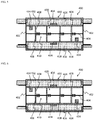
- FIG. 5 illustrates an electrolytic cell used in the brine electrolytic apparatus of the first reference embodiment, and illustrates a cross-sectional view along A-A' in FIG. 1 (a horizontal cross-sectional view).
- the first reference embodiment has the same structure as the first embodiment. Accordingly, an anode 314 and a buffer plate 316 disposed inside an anode chamber 310 are the same as those described in the first embodiment.
- a reverse current absorption body 334 of the type described in the first embodiment is coupled to a cathode current collector 328 inside a cathode chamber 320.
- the reverse current absorption body 334 may be a body that has been immersed in a solution containing an alkali metal hydroxide following sintering, thereby removing alkali-soluble components from regions near the surface.
- the sintered compact obtained following sintering may be used, as is, as the reverse current absorption body 334, and coupled to the cathode current collector 328.
- the reverse current absorption body 334 may be installed on the surface of the cathode current collector 328 on the side facing the cathode 330, or may be installed on the surface on the side facing a partition wall 304 (the surface on the opposite side from the cathode 330).
- the reverse current absorption body 334 is coupled to the cathode current collector 328 in a detachable manner.
- the method used for coupling the reverse current absorption body 334 to the cathode current collector 328 may employ similar methods to those described in the first embodiment such as securing by wire or welding.
- the reverse current absorption body 334 can be secured by sandwiching between the cathode current collector 328 and an elastic body 326. Further, the reverse current absorption body 334 may be coated with a wire gauze such as a woven mesh before being coupled to the cathode current collector 328.
- a conductive substrate 332 of the cathode 330, the elastic body 326, the cathode current collector 328, a frame 302, and supports 308 are formed from metal materials having conductivity.
- the cathode 330 and the reverse current absorption body 334 are connected electrically.
- a second reference embodiment of the present invention is an alkaline water electrolytic apparatus.
- FIG. 6 illustrates an electrolytic cell applicable to the second reference embodiment, and illustrates a cross-sectional view along A-A' in FIG. 1 (a horizontal cross-sectional view).
- FIG. 6 illustrates an example in which the embodiment is applied to a bipolar alkaline water electrolyzer, but this reference embodiment may also be applied to a monopolar electrolyzer.
- the second reference embodiment has the same structure as the second embodiment.
- a reverse current absorption body 434 of the type described in the first embodiment is coupled to at least one of an anode current collector 418 and a cathode current collector 428.
- the reverse current absorption body 434 may be a body that has been immersed in advance in a solution containing an alkali metal hydroxide (the production step A), or may be a body that has not been treated following sintering (the production step B).
- the reverse current absorption body 434 may each be located on either a surface on the electrode side (an anode 414 or a cathode 430) or a surface on the side of a partition wall 404.
- the reverse current absorption bodies 434 are coupled to the anode current collector 418 and the cathode current collector 428 in a detachable manner.
- the method used for performing the coupling to the anode current collector 418 and the cathode current collector 428 may employ securing by wire, or welding or the like.
- the reverse current absorption body 434 may be secured by sandwiching between the anode current collector 418 and an elastic body 416, or between the cathode current collector 428 and an elastic body 426. Further, the reverse current absorption bodies 434 may be coated with a wire gauze such as a woven mesh before being coupled to the anode current collector 418 and the cathode current collector 428.
- a conductive substrate 432 of the cathode 430, the elastic body 426, the cathode current collector 428, a frame 402, and support members 408 are formed from metal materials having conductivity.
- the cathode 430 and the reverse current absorption body 434 are connected electrically inside a cathode chamber 420.
- anode 414, the elastic body 416 and the anode current collector 418 are formed from metal materials having conductivity. As a result, the anode 414 and the reverse current absorption body 434 are connected electrically inside an anode chamber 410.
- the reverse current absorption bodies 434 are connected electrically to the anode 414 or the cathode 430. Accordingly, when operation of the electrolyzer is stopped and a reverse current is generated, the reactions (1) and (2) proceed at the cathode side. Because the cathode 430 is maintained at the same potential as the reverse current absorption body 434, oxidation reactions do not proceed at the cathode 430 while the reactions (1) and (2) are occurring, meaning the catalyst is protected. Further, the reactions (5), (6) and (7) proceed at the anode side, and because the anode 414 is maintained at the same potential as the reverse current absorption body 434, cathodic polarization does not occur beyond this potential. As a result, when electrolysis is restarted, anode degradation due to catalyst elution or a deterioration in conductivity can be prevented.
- a third reference embodiment of the present invention is a brine electrolytic apparatus.
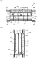
- FIG. 7 illustrates an electrolytic cell applicable to the third reference embodiment, and illustrates a cross-sectional view along A-A' in FIG. 1 (a horizontal cross-sectional view).
- FIG. 8 also illustrates an electrolytic cell applicable to the third reference embodiment, and illustrates a cross-sectional view along B-B' in FIG. 1 (a vertical cross-sectional view).
- FIG. 7 and FIG. 8 illustrate an example in which the embodiment is applied to a bipolar brine electrolyzer, but this reference embodiment may also be applied to a monopolar electrolyzer or an alkali sulfate electrolytic apparatus.
- the third reference embodiment has the same structure as the first embodiment. Accordingly, an anode 514 and a buffer plate 516 disposed inside an anode chamber 510 are the same as those described in the first embodiment.
- a reverse current absorption body 534 of the type described in the first embodiment is coupled to an electrolytic cell structural member inside a cathode chamber 520.
- the reverse current absorption body 534 may be a body that has been immersed in advance in a solution containing an alkali metal hydroxide (the production step A), or may be a body that has not been treated following sintering (the production step B).
- the electrolytic cell structural member refers to a member that constitutes part of the electrolytic cell besides a cathode structure (a cathode 530, a cathode current collector 528 and an elastic body 526) and an anode 514, and specific examples of this member include a frame 502, a partition wall 504, a support member (rib) 508, a gasket 506, and a buffer plate 516.
- this type of integrated structure is also included within the definition of electrolytic cell structural members.
- reverse current absorption bodies 534 are attached, in a detachable manner, to a surface of the partition wall 504 on the side of the cathode chamber 520, a side wall 502A of the frame 502 on the inside of the cathode chamber, a surface of the frame 502 on a bottom surface 502B (see FIG. 8 ) of the cathode chamber 520, and a support member 508.
- a reverse current absorption body 534 may also be installed in a position on the support member 508 on the side that contacts the cathode 530, provided it does not impair the function of the elastic body.
- a spring-like structure or coil-like structure may be formed on the support member 508 as an elastic body that contacts the cathode 530, and a reverse current absorption body 534 may be attached in a location in which the elastic body is not formed.
- the reverse current absorption bodies 534 are preferably coupled to the electrolytic cell structural members described above by welding, but may also be attached by metal securing means such as wires, provided the bodies can be secured satisfactorily. Further, the reverse current absorption bodies 534 may be coated with a wire gauze such as a woven mesh before being coupled to the electrolytic cell structural members.
- the reverse current absorption bodies 534 and the cathode 530 are connected electrically via the partition wall 504, the frame 502, the support members 508, the cathode current collector 528 and the elastic body 526.
- the cathode 530 When operation of the electrolyzer is stopped and a reverse current is generated, the cathode 530 is maintained at the same potential as the reverse current absorption bodies 534. As a result, oxidation reactions at the cathode 530 do not occur while the oxidation reactions of the reactions (1) and (2) are proceeding in the reverse current absorption bodies 534, meaning the catalyst is protected.
- a fourth reference embodiment of the present invention is an alkaline water electrolytic apparatus.
- FIG. 9 illustrates an electrolytic cell applicable to the fourth reference embodiment, and illustrates a cross-sectional view along A-A' in FIG. 1 (a horizontal cross-sectional view).
- FIG. 9 illustrates an example in which the embodiment is applied to a bipolar alkaline water electrolyzer, but this reference embodiment may also be applied to a monopolar electrolyzer.
- the fourth reference embodiment has the same structure as the second embodiment.
- reverse current absorption bodies 634 of the type described in the first embodiment are coupled to electrolytic cell structural members inside an anode chamber 610 and a cathode chamber 620.
- the electrolytic cell structural members refer to members that constitute part of the electrolytic cell besides a cathode structure (a cathode 630, a cathode current collector 628 and an elastic body 626) and an anode structure (an anode 614, an anode current collector 618 and an elastic body 616), and specific examples of these members include a frame 602, a partition wall 604, support members (ribs) 608, and a gasket 606. Accordingly, the reverse current absorption bodies 634 are attached to the partition wall 604, the inner wall surface of the frame 602, the bottom surface of the frame (not shown in FIG. 9 ), and the support members 608.
- the reverse current absorption bodies 634 may be installed in only one of the anode chamber 610 and a cathode chamber 620, or may be installed in both chambers.
- the support members 608 may be integrated with the cathode current collector and the elastic body, or integrated with the anode current collector and the elastic body, and these types of integrated structures are also included within the definition of electrolytic cell structural members.
- the reverse current absorption body 634 may be installed in a position on the side of the integrated structure that contacts the cathode 630 or the anode 614, in a similar manner to that described for the third reference embodiment.
- the reverse current absorption bodies 634 are preferably coupled to the electrolytic cell structural members described above by welding, but may also be attached by metal securing means such as wires. Further, the reverse current absorption bodies 634 may be coated with a wire gauze such as a woven mesh before being coupled to the electrolytic cell structural members.
- the reverse current absorption bodies 634 are connected electrically to the cathode 630 and the anode 614 via the partition wall 604, the frame 602, the support members 608, the cathode current collector 628, the anode current collector 618, and the elastic bodies 616 and 626.
- the molded body was sintered at 700°C for 2 hours.
- the thus obtained sintered compact was immersed in a 30 wt% aqueous solution of NaOH at 90°C for 2 hours to elute the alkali-soluble component (Al) in the sintered compact.
- the above sintered compact was secured as a reverse current absorption body to an active cathode with an area of 4 cm 2 .
- a nickel woven mesh having a catalyst layer containing Ru formed on the surface was used as the active cathode.
- the sintered compact was attached to the elastic body-side surface of the cathode in substantially the central portion of the cathode.
- An elastic body (coil cushion formed from nickel) and the above cathode were disposed on a cathode current collector (pure nickel expanded metal) to form a cathode structure.
- electrolysis was performed under the following conditions.
- Example 1 After completion of the electrolysis, a reverse current of 400 A/m 2 was applied.
- the discharge capacity of Example 1 was calculated from the amount of electricity required for the cathode potential to reach 0 V (vs. Hg/HgO).
- the discharge capacity varies depending on the experimental conditions, but in this example, is the value obtained when electrolysis was performed under the above electrolysis conditions for one hour at 10 kA/m 2 , and a reverse current of 400 A/m 2 was subsequently applied.
- a sintered compact prepared using the same method as Example 1 was disposed as a reverse current absorption body on a cathode current collector (pure nickel expanded metal).
- a woven mesh (of nickel) was mounted on top of the sintered compact, and an elastic body (coil cushion formed from nickel) and an active cathode with an area of 4 cm 2 (having a catalyst layer containing Ru formed on the surface of a nickel woven mesh) were then disposed on top, forming a cathode structure.
- electrolysis was performed under the same conditions as Example 1.
- Reference Example 1 After completion of the electrolysis, a reverse current of 400 A/m 2 was applied.
- the discharge capacity of Reference Example 1 was calculated from the amount of electricity required for the cathode potential to reach 0 V (vs. Hg/HgO).
- a substrate (nickel expanded metal) was subjected to Raney nickel dispersive plating, forming a reverse current absorption body provided with a thin-film reverse current absorption layer of about 300 ⁇ m.
- This reverse current absorption body of Comparative Example 1 was used as a current collector, and combined with a similar elastic body and cathode to those used in Reference Example 1 to prepare a cathode structure. This cathode structure was then subjected to electrolysis and reverse current application under the same conditions as Example 1, and the discharge capacity of Comparative Example 1 was calculated.
- Example 1 The discharge capacity of Example 1 was 13.99 mF/g (95.53 F/m 2 ).
- the discharge capacity of Reference Example 1 was 14.18 mF/g (96.88 F/m 2 ).
- the discharge capacity of Comparative Example 1 was 3.31 F/m 2
- the discharge capacity of Comparative Example 2 was 0.07 F/m 2 . In this manner, it is evident that when a reverse current absorption body formed from a sintered compact is installed (Example 1, Reference Example 1), the discharge capacity improves dramatically.
- Example 2 Using the same cathode structure as Example 1, electrolysis was performed at a current density of 10 kA/m 2 for 12 hours. Subsequently, a cycle of applying a reverse current for 5 hours was repeated 100 times. The reverse current was applied so that the cumulative amount of electricity relative to the reverse current absorption body was 3.66 mF/g (25 F/m 2 ) per cycle.
- Example 2 Using the same cathode structure as Comparative Example 2, electrolysis and reverse current application were performed under the same conditions as Example 2.
- FIG. 10 is a graph illustrating the change in the hydrogen overvoltage of the active cathode during the reverse current application cycles.
- the horizontal axis represents the cycle number
- the vertical axis represents the hydrogen overvoltage when the current density is 6 kA/m 2 .
- Example 2 no ruthenium elution was confirmed during the 100 cycles.
- the increase in the hydrogen overvoltage following completion of the 100 cycles was about 10 to 20 mV, indicating almost no degradation.
- Comparative Example 3 ruthenium elution was confirmed in each cycle. After the completion of 15 cycles, the hydrogen overvoltage of the active cathode had increased about 150 mV from the initial value. In the case of Comparative Example 3, the test was halted after 15 cycles.
- Example 1 Using the same procedure as Example 1, the thus obtained sintered compacts were each coupled as a reverse current absorption body to an active cathode (of the same type as Example 1), thus forming a series of cathode structures. Electrolysis and reverse current application were then performed under the same conditions as Example 1, and the discharge capacity of each example was calculated. The results are shown in Table 1.
- Table 1 Metallic nickel particles average particle size ( ⁇ m) Discharge capacity (mF/g) (F/m 2 ) Sample 1 0.13 2.24 15.39 Sample 2 0.2 3.13 20.16 Sample 3 0.4 5.83 39.58 Sample 4 2.5 6.38 44.34 Sample 5 4 9.23 62.65 Sample 6 10 2.92 20.02 Sample 7 50 2.06 13.27 Sample 8 100 The sample did not maintain its shape after immersion
- Ni-Al-Ru-Sn Raney alloy particles (average particle size: 45 ⁇ m) were prepared as Raney nickel alloy particles.
- These Raney nickel alloy particles and the metallic nickel particles of Example 1 were mixed together in a ratio of 50:50 (mass ratio) to obtain a raw material powder.
- Ni-Al-Ti-Ru-Co Raney alloy particles (average particle size: 45 ⁇ m) were prepared as Raney nickel alloy particles.
- These Raney nickel alloy particles and the metallic nickel particles of Example 1 were mixed together in a ratio of 50:50 (mass ratio) to obtain a raw material powder.
- Each molded body was sintered at 700°C for 2 hours.
- the thus obtained sintered compacts were each immersed in a 30 wt% aqueous solution of NaOH at 90°C for 7 hours to elute the alkali-soluble component (Al) in the sintered compact.
- each of the above sintered compacts was coupled as a reverse current absorption body to an active cathode (of the same type as Example 1), thus forming a cathode structure. Electrolysis and reverse current application were then performed under the same conditions as Example 1, and the discharge capacity was calculated.
- Example 4 The discharge capacity of Example 4 was 10.84 mF/g (73.66 F/m 2 ).
- the discharge capacity of Example 5 was 3.60 mF/g (24.44 F/m 2 ).
- Example 2 Using the same procedure as Example 1, the thus obtained sintered compacts were each coupled as a reverse current absorption body to an active cathode (of the same type as Example 1), thus forming a series of cathode structures. Electrolysis and reverse current application were then performed under the same conditions as Example 1, and the discharge capacity of each example was calculated. The results are shown in Table 2.
- the "nickel content” represents the value determined from the total amount of nickel in the metallic nickel particles and the nickel-aluminum alloy particles prior to the immersion step.
- the relationship between the discharge capacity and the sintered compact density in Table 2 is shown in FIG. 11 .
- the values before the immersion step have a curve (solid line in the figure) that decreases gently toward the right from the value when the nickel content is 100% (7.58 g/cm3, 0.06 mF/g). Further, the values after the immersion step also decrease toward the right from the value when the nickel content is 100% (7.58 g/cm3, 0.06 mF/g), and follow a curve (dashed line in the figure) positioned below the curve for the values before the immersion step.
- Example 3 Using the same procedure as Example 1, the thus obtained sintered compacts were each coupled as a reverse current absorption body to an active cathode (of the same type as Example 1), thus forming a series of cathode structures. Electrolysis and reverse current application were then performed under the same conditions as Example 1, and the discharge capacity of each example was calculated. The results are shown in Table 3.
- FIG. 12 A graph obtained by adding the relationship between the discharge capacity and the sintered compact density in Table 3 to the values in FIG. 11 is shown in FIG. 12 .
- the values exhibit a similar discharge capacity - sintered compact density relationship to that observed when the average particle size is 4 ⁇ m.
- the values before the immersion step have a curve (solid line in the figure) that decreases gently toward the right from the value when the nickel content is 100% (7.58 g/cm 3 , 0.06 mF/g).
- the values after the immersion step also decrease gently toward the right from the value when the nickel content is 100% (7.58 g/cm 3 , 0.06 mF/g), and follow a curve (dashed line in the figure) positioned below the curve for the values before the immersion step. Based on the results of Example 6 and Example 7, it is evident that this discharge capacity - sintered compact density relationship applies even when the particle size of the metallic nickel particles is changed.
- the relationship between the discharge capacity and the sintered compact density changes in the manner shown in the shaded region in FIG. 13 , and satisfies the correlations shown in FIG. 11 and FIG. 12 at each particle size. From FIG. 13 it is evident that the results at which the discharge capacity - sintered compact density correlation is farthest right are when the average particle size of the nickel is 4 ⁇ m. If this observation is considered in combination with the fact that the discharge capacity - sintered compact density correlation is a curve that decreases gently toward the right, then the sintered compact densities that exhibit the same amount of reverse current absorption exhibit a maximum when the nickel average particle size is 4 ⁇ m.
- the sintered compact must have a discharge capacity of at least 1.5 mF/g (10 F/m 2 ).
- the upper limit for the density of a sintered compact of nickel particles having an average particle size of 4 ⁇ m is 6.51 g/cm3.
- the nickel content in the reverse current absorption body is preferably from 45 to 90% by mass. Provided the nickel content is within this range, the shape of the reverse current absorption body can be maintained even after the immersion step, and a high discharge capacity exceeding 1.5 mF/g (10 F/m 2 ) can be obtained. From the viewpoint of durability, this nickel content is more preferably from 53 to 90% by mass. Moreover, if the reverse current absorption performance is also taken into consideration, then the nickel content is even more preferably from 53 to 87.5% by mass, and is most preferably from 53 to 77.5% by mass.
- the density of the reverse current absorption body is preferably from 2.00 to 6.51 g/cm 3 . Provided the density is within this range, the shape of the reverse current absorption body can be maintained even after the immersion step, and a high discharge capacity exceeding 1.5 mF/g (10 F/m 2 ) can be obtained. From the viewpoint of durability, this density is more preferably from 2.30 to 6.51 g/cm 3 . Moreover, if the reverse current absorption performance is also taken into consideration, then the density is even more preferably from 2.30 to 5.95 g/cm 3 , and is most preferably from 2.30 to 5.10 g/cm 3 .
Landscapes
- Chemical & Material Sciences (AREA)
- Engineering & Computer Science (AREA)
- Chemical Kinetics & Catalysis (AREA)
- Electrochemistry (AREA)
- Materials Engineering (AREA)
- Metallurgy (AREA)
- Organic Chemistry (AREA)
- Inorganic Chemistry (AREA)
- Electrolytic Production Of Non-Metals, Compounds, Apparatuses Therefor (AREA)
- Electrodes For Compound Or Non-Metal Manufacture (AREA)
Claims (8)
- Elektrode für Elektrolyse, umfassend:Ein leitfähiges Substrat, auf dem eine Katalysatorschicht gebildet wird, undzumindest einen Rückstromabsorptionskörper, der:(i) direkt auf eine lösbare Weise an das leitfähige Substrat gekoppelt ist, oder(ii) mit einer Drahtgaze beschichtet ist, die auf eine lösbare Weise direkt an das leitfähige Substrat gekoppelt istwobei der zumindest eine Rückstromabsorptionskörper aus einem Nickel enthaltenden gesinterten Presskörper geformt ist, undwobei der Rückstromabsorptionskörper kein Substrat enthält.
- Elektrode für Elektrolyse nach Anspruch 1, wobei der zumindest eine Rückstromabsorptionskörper an einen Endabschnitt des leitfähigen Substrats gekoppelt ist.
- Elektrode für Elektrolyse nach Anspruch 1, wobei ein Nickelgehalt im Nickel enthaltenden gesinterten Presskörper von 45 bis 90 Gew.-% beträgt.
- Elektrode für Elektrolyse nach Anspruch 1, wobei eine Dichte des zumindest einen Rückstromabsorptionskörpers von 2,00 bis 6,51 g/cm3 beträgt.
- Verfahren zur Herstellung der Elektrode für Elektrolyse nach einem der Ansprüche 1 bis 4, wobei das Verfahren umfasst:Einen Schritt zur Bildung des gesinterten Presskörpers durch Erhalten des gesinterten Presskörpers durch Sintern eines Rohmaterialpulvers, das aus irgendwelchen Raney-Nickellegierungspartikeln besteht, die Nickel und ein alkalilösliches Metallelement, metallische Nickelpartikel, und eine Mischung aus Raney-Nickellegierungspartikeln und die metallischen Nickelpartikel enthalten, undEinen Schritt zum Koppeln des gesinterten Presskörpers an das leitfähige Substrat.
- Verfahren zur Herstellung der Elektrode für Elektrolyse nach Anspruch 5, ferner umfassend:
Einen Eintauchschritt nach dem Koppeln des Eintauchens des gesinterten Presskörpers, der beim Schritt der Kopplung an das leitfähige Substrat gekoppelt worden ist, in einen Elektrolyt, der ein Alkalimetallhydroxid enthält. - Verfahren zur Herstellung der Elektrode für Elektrolyse nach Anspruch 5, ferner umfassend:Einen Eintauchschritt vor dem Koppeln des Eintauchens des gesinterten Presskörpers, der beim Schritt zur Bildung des gesinterten Presskörpers erhalten wurde, in eine Lösung, die ein Alkalimetallhydroxid enthält, wobeider gesinterte Presskörper, der dem Eintauchschritt vor dem Koppeln unterzogen wurde, danach beim Kopplungsschritt an das leitfähige Substrat gekoppelt wird.
- Elektrolysevorrichtung mit einer Anode, einer Anodenkammer, in der die Anode untergebracht ist, einer Kathode, einer Kathodenkammer, in der die Kathode untergebracht ist, und einer Membrane, welche die Anodenkammer und die Kathodenkammer trennt, wobei
zumindest eine der Kathode und der Anode die Elektrode für Elektrolyse nach einem der Ansprüche 1 bis 4 ist.
Applications Claiming Priority (2)
| Application Number | Priority Date | Filing Date | Title |
|---|---|---|---|
| JP2016089143 | 2016-04-27 | ||
| PCT/JP2017/016872 WO2017188421A1 (ja) | 2016-04-27 | 2017-04-27 | 電解用電極、電解用電極の製造方法及び電解槽 |
Publications (3)
| Publication Number | Publication Date |
|---|---|
| EP3330409A1 EP3330409A1 (de) | 2018-06-06 |
| EP3330409A4 EP3330409A4 (de) | 2018-10-31 |
| EP3330409B1 true EP3330409B1 (de) | 2020-12-16 |
Family
ID=60159830
Family Applications (2)
| Application Number | Title | Priority Date | Filing Date |
|---|---|---|---|
| EP17789703.0A Active EP3330410B1 (de) | 2016-04-27 | 2017-04-27 | Elektrolysezelle |
| EP17789702.2A Active EP3330409B1 (de) | 2016-04-27 | 2017-04-27 | Elektrode für elektrolyse, herstellungsverfahren für elektrode für elektrolyse und elektrolysezelle |
Family Applications Before (1)
| Application Number | Title | Priority Date | Filing Date |
|---|---|---|---|
| EP17789703.0A Active EP3330410B1 (de) | 2016-04-27 | 2017-04-27 | Elektrolysezelle |
Country Status (11)
| Country | Link |
|---|---|
| US (2) | US10669638B2 (de) |
| EP (2) | EP3330410B1 (de) |
| JP (2) | JP6383897B2 (de) |
| KR (2) | KR102047351B1 (de) |
| CN (2) | CN107849710B (de) |
| AU (2) | AU2017257930B2 (de) |
| CA (2) | CA3017473C (de) |
| CL (2) | CL2018000312A1 (de) |
| HK (2) | HK1247647B (de) |
| WO (2) | WO2017188422A1 (de) |
| ZA (1) | ZA201807095B (de) |
Families Citing this family (15)
| Publication number | Priority date | Publication date | Assignee | Title |
|---|---|---|---|---|
| JP6831451B2 (ja) * | 2017-03-13 | 2021-02-17 | 旭化成株式会社 | 電解セル及び電解槽 |
| MY202878A (en) | 2018-03-27 | 2024-05-28 | Tokuyama Corp | Electrolysis vessel for alkaline water electrolysis |
| WO2020100251A1 (ja) | 2018-11-15 | 2020-05-22 | 三菱重工エンジン&ターボチャージャ株式会社 | 遠心圧縮機及びこの遠心圧縮機を備えたターボチャージャ |
| KR102776320B1 (ko) * | 2019-07-05 | 2025-03-07 | 주식회사 엘지화학 | 역전류 방지 방법 및 역전류 방지 시스템 |
| KR20210062319A (ko) | 2019-11-21 | 2021-05-31 | 김희환 | 식감과 영양소가 우수한 고기만두 및 그 제조방법 |
| KR20210069856A (ko) | 2019-12-04 | 2021-06-14 | 김희환 | 식감과 영양소가 우수한 김치만두 및 그 제조방법 |
| CN113145120B (zh) * | 2021-04-02 | 2022-06-07 | 浙江大学 | 一种原位出溶型催化剂及其制备方法和应用 |
| JP7804412B2 (ja) * | 2021-08-25 | 2026-01-22 | 株式会社東芝 | 水電解装置、及び水電解セルの制御方法 |
| KR102730632B1 (ko) * | 2021-12-13 | 2024-11-15 | 주식회사 티에프이 | 러버 소켓용 도전성 부재 제조 방법 |
| WO2023181133A1 (ja) * | 2022-03-22 | 2023-09-28 | 冨士ダイス株式会社 | 電極及びその製造方法 |
| US12362432B2 (en) | 2022-10-31 | 2025-07-15 | Verdagy, Inc. | Protective insert for electrochemical cell |
| WO2024243671A1 (en) * | 2023-05-29 | 2024-12-05 | Noram Electrolysis Systems Inc. | Apparatuses and methods for multi-stage electrolysis |
| IT202300014220A1 (it) | 2023-07-07 | 2025-01-07 | Industrie De Nora Spa | Processo per la fabbricazione di elementi protettivi per celle di cloro-alcali ed elettrolisi alcalina dell'acqua |
| TW202546275A (zh) * | 2023-12-28 | 2025-12-01 | 日商豐田自動織機股份有限公司 | 水電解用陰極及水電解用陰極之製造方法 |
| TW202546273A (zh) * | 2023-12-28 | 2025-12-01 | 日商豐田自動織機股份有限公司 | 水電解用電極及水電解用電極之製造方法 |
Family Cites Families (25)
| Publication number | Priority date | Publication date | Assignee | Title |
|---|---|---|---|---|
| FR2215699B1 (de) * | 1973-01-30 | 1976-04-30 | Commissariat Energie Atomique | |
| US4169025A (en) * | 1976-11-17 | 1979-09-25 | E. I. Du Pont De Nemours & Company | Process for making catalytically active Raney nickel electrodes |
| US4225346A (en) * | 1978-09-08 | 1980-09-30 | Bell Telephone Laboratories, Incorporated | Process for fabricating porous nickel bodies |
| JPS6146046A (ja) * | 1984-08-10 | 1986-03-06 | Hitachi Ltd | 半導体集積回路装置 |
| JPS61146046A (ja) | 1984-12-20 | 1986-07-03 | Osaka Gas Co Ltd | 行先の表示および電話機の切換えを行なう装置 |
| JPS61204397A (ja) * | 1985-03-07 | 1986-09-10 | Hitachi Cable Ltd | めつき装置 |
| JPS62182294A (ja) * | 1986-02-07 | 1987-08-10 | Mitsubishi Heavy Ind Ltd | 電解槽の逆電流低減装置 |
| JP3236682B2 (ja) * | 1992-11-05 | 2001-12-10 | ペルメレック電極株式会社 | 電解用陰極及びその製造方法 |
| US5861225A (en) * | 1992-11-12 | 1999-01-19 | Ovonic Battery Company, Inc. | Nickel battery electrode having multiple composition nickel hydroxide active materials |
| US6177213B1 (en) * | 1998-08-17 | 2001-01-23 | Energy Conversion Devices, Inc. | Composite positive electrode material and method for making same |
| JP2001234379A (ja) | 2000-02-16 | 2001-08-31 | Asahi Kasei Corp | 電解用陰極 |
| JP4115686B2 (ja) * | 2000-11-02 | 2008-07-09 | ペルメレック電極株式会社 | 電極構造体及び該構造体を使用する電解方法 |
| JP2002203186A (ja) | 2000-12-28 | 2002-07-19 | Fujitsu Ltd | 書類作成方法、書類作成装置、および記録媒体 |
| US7928310B2 (en) * | 2002-11-12 | 2011-04-19 | MediaLab Solutions Inc. | Systems and methods for portable audio synthesis |
| JP2004323955A (ja) * | 2003-04-28 | 2004-11-18 | Wako Sangyo:Kk | 電解用電極及びその製造方法 |
| JP4284387B2 (ja) | 2003-09-12 | 2009-06-24 | 株式会社和功産業 | 電解用電極及びその製造方法 |
| CN101029405B (zh) | 2006-02-28 | 2010-12-22 | 蓝星(北京)化工机械有限公司 | 活性阴极及其制备方法 |
| BRPI0914129A8 (pt) | 2008-07-03 | 2017-09-19 | Asahi Kasei Chemicals Corp | Catodo para geração de hidrogênio, elettrolisador para eletrólise de um cloreto de metal alcalino, e, método para produzir o catodo para geração de hidrogênio |
| JP5317012B2 (ja) | 2009-03-11 | 2013-10-16 | ダイソー株式会社 | 低水素過電圧陰極の製法 |
| JP4846869B1 (ja) | 2010-09-07 | 2011-12-28 | クロリンエンジニアズ株式会社 | 電解用陰極構造体およびそれを用いた電解槽 |
| SG193922A1 (en) | 2011-04-05 | 2013-11-29 | Blacklight Power Inc | H2o-based electrochemical hydrogen-catalyst power system |
| ES2593354T3 (es) * | 2012-03-19 | 2016-12-07 | Asahi Kasei Kabushiki Kaisha | Celda de electrólisis y cuba electrolítica |
| DK2862960T3 (da) | 2012-06-18 | 2020-03-23 | Asahi Chemical Ind | Bipolær alkalisk vandelektrolyseenhed |
| US8766050B2 (en) * | 2012-07-02 | 2014-07-01 | Mertec, Llc | Soybean cultivar XB35H12 |
| JP6438205B2 (ja) | 2014-03-25 | 2018-12-12 | 旭化成株式会社 | 水電解セル |
-
2017
- 2017-04-27 EP EP17789703.0A patent/EP3330410B1/de active Active
- 2017-04-27 WO PCT/JP2017/016873 patent/WO2017188422A1/ja not_active Ceased
- 2017-04-27 JP JP2018509863A patent/JP6383897B2/ja active Active
- 2017-04-27 JP JP2018509864A patent/JP6339753B2/ja active Active
- 2017-04-27 US US15/753,631 patent/US10669638B2/en active Active
- 2017-04-27 CN CN201780002563.6A patent/CN107849710B/zh active Active
- 2017-04-27 CN CN201780002570.6A patent/CN107923053B/zh active Active
- 2017-04-27 US US15/753,646 patent/US10590551B2/en active Active
- 2017-04-27 AU AU2017257930A patent/AU2017257930B2/en active Active
- 2017-04-27 KR KR1020187034211A patent/KR102047351B1/ko active Active
- 2017-04-27 CA CA3017473A patent/CA3017473C/en active Active
- 2017-04-27 WO PCT/JP2017/016872 patent/WO2017188421A1/ja not_active Ceased
- 2017-04-27 HK HK18107015.6A patent/HK1247647B/zh unknown
- 2017-04-27 AU AU2017257929A patent/AU2017257929B2/en active Active
- 2017-04-27 EP EP17789702.2A patent/EP3330409B1/de active Active
- 2017-04-27 CA CA3017451A patent/CA3017451C/en active Active
- 2017-04-27 KR KR1020187034210A patent/KR102047350B1/ko active Active
- 2017-04-27 HK HK18107013.8A patent/HK1247646B/zh unknown
-
2018
- 2018-02-02 CL CL2018000312A patent/CL2018000312A1/es unknown
- 2018-02-02 CL CL2018000313A patent/CL2018000313A1/es unknown
- 2018-10-24 ZA ZA2018/07095A patent/ZA201807095B/en unknown
Non-Patent Citations (1)
| Title |
|---|
| None * |
Also Published As
Similar Documents
| Publication | Publication Date | Title |
|---|---|---|
| EP3330410B1 (de) | Elektrolysezelle | |
| HK1247646A1 (en) | Electrolyzer | |
| HK1247647A1 (en) | Electrode for electrolysis, manufacturing method of electrode for electrolysis, and electrolyzer | |
| EP3399070B1 (de) | Verfahren zur elektrolyse von alkalischem wasser | |
| EP2816141B1 (de) | Elektrolysezelle und elektrolysetank | |
| EP3597792B9 (de) | Elektrolysezelle und elektrolysebad | |
| EP2540872B1 (de) | Sauerstoffgasdiffusionskathode, elektrolysebad damit, verfahren zur herstellung von chlorgas und verfahren zur herstellung von natriumhydroxid | |
| JP6788378B2 (ja) | 水電解セル及び複極式水電解槽 | |
| EP2660357B1 (de) | Elektrolysezelle mit ionenaustauschmembran | |
| US4789452A (en) | Highly durable cathode of low hydrogen overvoltage and method for manufacturing the same | |
| RU2575343C1 (ru) | Электролизная ячейка и электролизер | |
| EP4484616A1 (de) | Elektrode und verfahren zur herstellung davon |
Legal Events
| Date | Code | Title | Description |
|---|---|---|---|
| STAA | Information on the status of an ep patent application or granted ep patent |
Free format text: STATUS: THE INTERNATIONAL PUBLICATION HAS BEEN MADE |
|
| PUAI | Public reference made under article 153(3) epc to a published international application that has entered the european phase |
Free format text: ORIGINAL CODE: 0009012 |
|
| STAA | Information on the status of an ep patent application or granted ep patent |
Free format text: STATUS: REQUEST FOR EXAMINATION WAS MADE |
|
| 17P | Request for examination filed |
Effective date: 20180227 |
|
| AK | Designated contracting states |
Kind code of ref document: A1 Designated state(s): AL AT BE BG CH CY CZ DE DK EE ES FI FR GB GR HR HU IE IS IT LI LT LU LV MC MK MT NL NO PL PT RO RS SE SI SK SM TR |
|
| AX | Request for extension of the european patent |
Extension state: BA ME |
|
| REG | Reference to a national code |
Ref country code: DE Ref legal event code: R079 Ref document number: 602017029729 Country of ref document: DE Free format text: PREVIOUS MAIN CLASS: C25B0011040000 Ipc: C25B0001100000 |
|
| STAA | Information on the status of an ep patent application or granted ep patent |
Free format text: STATUS: EXAMINATION IS IN PROGRESS |
|
| A4 | Supplementary search report drawn up and despatched |
Effective date: 20181001 |
|
| RIC1 | Information provided on ipc code assigned before grant |
Ipc: C25B 9/20 20060101ALI20180925BHEP Ipc: C25B 9/08 20060101ALI20180925BHEP Ipc: C25B 1/46 20060101ALI20180925BHEP Ipc: C25B 1/10 20060101AFI20180925BHEP |
|
| 17Q | First examination report despatched |
Effective date: 20181019 |
|
| DAV | Request for validation of the european patent (deleted) | ||
| DAX | Request for extension of the european patent (deleted) | ||
| GRAP | Despatch of communication of intention to grant a patent |
Free format text: ORIGINAL CODE: EPIDOSNIGR1 |
|
| STAA | Information on the status of an ep patent application or granted ep patent |
Free format text: STATUS: GRANT OF PATENT IS INTENDED |
|
| INTG | Intention to grant announced |
Effective date: 20200706 |
|
| GRAS | Grant fee paid |
Free format text: ORIGINAL CODE: EPIDOSNIGR3 |
|
| GRAA | (expected) grant |
Free format text: ORIGINAL CODE: 0009210 |
|
| STAA | Information on the status of an ep patent application or granted ep patent |
Free format text: STATUS: THE PATENT HAS BEEN GRANTED |
|
| REG | Reference to a national code |
Ref country code: DE Ref legal event code: R079 Ref document number: 602017029729 Country of ref document: DE Free format text: PREVIOUS MAIN CLASS: C25B0001100000 Ipc: C25B0001040000 |
|
| AK | Designated contracting states |
Kind code of ref document: B1 Designated state(s): AL AT BE BG CH CY CZ DE DK EE ES FI FR GB GR HR HU IE IS IT LI LT LU LV MC MK MT NL NO PL PT RO RS SE SI SK SM TR |
|
| REG | Reference to a national code |
Ref country code: GB Ref legal event code: FG4D |
|
| REG | Reference to a national code |
Ref country code: IE Ref legal event code: FG4D |
|
| REG | Reference to a national code |
Ref country code: DE Ref legal event code: R096 Ref document number: 602017029729 Country of ref document: DE |
|
| REG | Reference to a national code |
Ref country code: AT Ref legal event code: REF Ref document number: 1345683 Country of ref document: AT Kind code of ref document: T Effective date: 20210115 |
|
| PG25 | Lapsed in a contracting state [announced via postgrant information from national office to epo] |
Ref country code: FI Free format text: LAPSE BECAUSE OF FAILURE TO SUBMIT A TRANSLATION OF THE DESCRIPTION OR TO PAY THE FEE WITHIN THE PRESCRIBED TIME-LIMIT Effective date: 20201216 Ref country code: RS Free format text: LAPSE BECAUSE OF FAILURE TO SUBMIT A TRANSLATION OF THE DESCRIPTION OR TO PAY THE FEE WITHIN THE PRESCRIBED TIME-LIMIT Effective date: 20201216 Ref country code: GR Free format text: LAPSE BECAUSE OF FAILURE TO SUBMIT A TRANSLATION OF THE DESCRIPTION OR TO PAY THE FEE WITHIN THE PRESCRIBED TIME-LIMIT Effective date: 20210317 Ref country code: NO Free format text: LAPSE BECAUSE OF FAILURE TO SUBMIT A TRANSLATION OF THE DESCRIPTION OR TO PAY THE FEE WITHIN THE PRESCRIBED TIME-LIMIT Effective date: 20210316 |
|
| REG | Reference to a national code |
Ref country code: AT Ref legal event code: MK05 Ref document number: 1345683 Country of ref document: AT Kind code of ref document: T Effective date: 20201216 |
|
| REG | Reference to a national code |
Ref country code: NL Ref legal event code: MP Effective date: 20201216 |
|
| PG25 | Lapsed in a contracting state [announced via postgrant information from national office to epo] |
Ref country code: BG Free format text: LAPSE BECAUSE OF FAILURE TO SUBMIT A TRANSLATION OF THE DESCRIPTION OR TO PAY THE FEE WITHIN THE PRESCRIBED TIME-LIMIT Effective date: 20210316 Ref country code: SE Free format text: LAPSE BECAUSE OF FAILURE TO SUBMIT A TRANSLATION OF THE DESCRIPTION OR TO PAY THE FEE WITHIN THE PRESCRIBED TIME-LIMIT Effective date: 20201216 Ref country code: LV Free format text: LAPSE BECAUSE OF FAILURE TO SUBMIT A TRANSLATION OF THE DESCRIPTION OR TO PAY THE FEE WITHIN THE PRESCRIBED TIME-LIMIT Effective date: 20201216 |
|
| PG25 | Lapsed in a contracting state [announced via postgrant information from national office to epo] |
Ref country code: NL Free format text: LAPSE BECAUSE OF FAILURE TO SUBMIT A TRANSLATION OF THE DESCRIPTION OR TO PAY THE FEE WITHIN THE PRESCRIBED TIME-LIMIT Effective date: 20201216 Ref country code: HR Free format text: LAPSE BECAUSE OF FAILURE TO SUBMIT A TRANSLATION OF THE DESCRIPTION OR TO PAY THE FEE WITHIN THE PRESCRIBED TIME-LIMIT Effective date: 20201216 |
|
| REG | Reference to a national code |
Ref country code: LT Ref legal event code: MG9D |
|
| PG25 | Lapsed in a contracting state [announced via postgrant information from national office to epo] |
Ref country code: SM Free format text: LAPSE BECAUSE OF FAILURE TO SUBMIT A TRANSLATION OF THE DESCRIPTION OR TO PAY THE FEE WITHIN THE PRESCRIBED TIME-LIMIT Effective date: 20201216 Ref country code: LT Free format text: LAPSE BECAUSE OF FAILURE TO SUBMIT A TRANSLATION OF THE DESCRIPTION OR TO PAY THE FEE WITHIN THE PRESCRIBED TIME-LIMIT Effective date: 20201216 Ref country code: CZ Free format text: LAPSE BECAUSE OF FAILURE TO SUBMIT A TRANSLATION OF THE DESCRIPTION OR TO PAY THE FEE WITHIN THE PRESCRIBED TIME-LIMIT Effective date: 20201216 Ref country code: EE Free format text: LAPSE BECAUSE OF FAILURE TO SUBMIT A TRANSLATION OF THE DESCRIPTION OR TO PAY THE FEE WITHIN THE PRESCRIBED TIME-LIMIT Effective date: 20201216 Ref country code: RO Free format text: LAPSE BECAUSE OF FAILURE TO SUBMIT A TRANSLATION OF THE DESCRIPTION OR TO PAY THE FEE WITHIN THE PRESCRIBED TIME-LIMIT Effective date: 20201216 Ref country code: PT Free format text: LAPSE BECAUSE OF FAILURE TO SUBMIT A TRANSLATION OF THE DESCRIPTION OR TO PAY THE FEE WITHIN THE PRESCRIBED TIME-LIMIT Effective date: 20210416 Ref country code: SK Free format text: LAPSE BECAUSE OF FAILURE TO SUBMIT A TRANSLATION OF THE DESCRIPTION OR TO PAY THE FEE WITHIN THE PRESCRIBED TIME-LIMIT Effective date: 20201216 |
|
| PG25 | Lapsed in a contracting state [announced via postgrant information from national office to epo] |
Ref country code: AT Free format text: LAPSE BECAUSE OF FAILURE TO SUBMIT A TRANSLATION OF THE DESCRIPTION OR TO PAY THE FEE WITHIN THE PRESCRIBED TIME-LIMIT Effective date: 20201216 Ref country code: PL Free format text: LAPSE BECAUSE OF FAILURE TO SUBMIT A TRANSLATION OF THE DESCRIPTION OR TO PAY THE FEE WITHIN THE PRESCRIBED TIME-LIMIT Effective date: 20201216 |
|
| REG | Reference to a national code |
Ref country code: DE Ref legal event code: R097 Ref document number: 602017029729 Country of ref document: DE |
|
| PG25 | Lapsed in a contracting state [announced via postgrant information from national office to epo] |
Ref country code: IS Free format text: LAPSE BECAUSE OF FAILURE TO SUBMIT A TRANSLATION OF THE DESCRIPTION OR TO PAY THE FEE WITHIN THE PRESCRIBED TIME-LIMIT Effective date: 20210416 |
|
| PLBE | No opposition filed within time limit |
Free format text: ORIGINAL CODE: 0009261 |
|
| STAA | Information on the status of an ep patent application or granted ep patent |
Free format text: STATUS: NO OPPOSITION FILED WITHIN TIME LIMIT |
|
| PG25 | Lapsed in a contracting state [announced via postgrant information from national office to epo] |
Ref country code: AL Free format text: LAPSE BECAUSE OF FAILURE TO SUBMIT A TRANSLATION OF THE DESCRIPTION OR TO PAY THE FEE WITHIN THE PRESCRIBED TIME-LIMIT Effective date: 20201216 |
|
| 26N | No opposition filed |
Effective date: 20210917 |
|
| PG25 | Lapsed in a contracting state [announced via postgrant information from national office to epo] |
Ref country code: MC Free format text: LAPSE BECAUSE OF FAILURE TO SUBMIT A TRANSLATION OF THE DESCRIPTION OR TO PAY THE FEE WITHIN THE PRESCRIBED TIME-LIMIT Effective date: 20201216 Ref country code: DK Free format text: LAPSE BECAUSE OF FAILURE TO SUBMIT A TRANSLATION OF THE DESCRIPTION OR TO PAY THE FEE WITHIN THE PRESCRIBED TIME-LIMIT Effective date: 20201216 |
|
| PG25 | Lapsed in a contracting state [announced via postgrant information from national office to epo] |
Ref country code: LU Free format text: LAPSE BECAUSE OF NON-PAYMENT OF DUE FEES Effective date: 20210427 |
|
| REG | Reference to a national code |
Ref country code: BE Ref legal event code: MM Effective date: 20210430 |
|
| PG25 | Lapsed in a contracting state [announced via postgrant information from national office to epo] |
Ref country code: LI Free format text: LAPSE BECAUSE OF NON-PAYMENT OF DUE FEES Effective date: 20210430 Ref country code: CH Free format text: LAPSE BECAUSE OF NON-PAYMENT OF DUE FEES Effective date: 20210430 Ref country code: ES Free format text: LAPSE BECAUSE OF FAILURE TO SUBMIT A TRANSLATION OF THE DESCRIPTION OR TO PAY THE FEE WITHIN THE PRESCRIBED TIME-LIMIT Effective date: 20201216 |
|
| PG25 | Lapsed in a contracting state [announced via postgrant information from national office to epo] |
Ref country code: SI Free format text: LAPSE BECAUSE OF FAILURE TO SUBMIT A TRANSLATION OF THE DESCRIPTION OR TO PAY THE FEE WITHIN THE PRESCRIBED TIME-LIMIT Effective date: 20201216 |
|
| PG25 | Lapsed in a contracting state [announced via postgrant information from national office to epo] |
Ref country code: IE Free format text: LAPSE BECAUSE OF NON-PAYMENT OF DUE FEES Effective date: 20210427 |
|
| PG25 | Lapsed in a contracting state [announced via postgrant information from national office to epo] |
Ref country code: IS Free format text: LAPSE BECAUSE OF FAILURE TO SUBMIT A TRANSLATION OF THE DESCRIPTION OR TO PAY THE FEE WITHIN THE PRESCRIBED TIME-LIMIT Effective date: 20210416 |
|
| PG25 | Lapsed in a contracting state [announced via postgrant information from national office to epo] |
Ref country code: BE Free format text: LAPSE BECAUSE OF NON-PAYMENT OF DUE FEES Effective date: 20210430 |
|
| P01 | Opt-out of the competence of the unified patent court (upc) registered |
Effective date: 20230516 |
|
| PG25 | Lapsed in a contracting state [announced via postgrant information from national office to epo] |
Ref country code: CY Free format text: LAPSE BECAUSE OF FAILURE TO SUBMIT A TRANSLATION OF THE DESCRIPTION OR TO PAY THE FEE WITHIN THE PRESCRIBED TIME-LIMIT Effective date: 20201216 |
|
| PG25 | Lapsed in a contracting state [announced via postgrant information from national office to epo] |
Ref country code: HU Free format text: LAPSE BECAUSE OF FAILURE TO SUBMIT A TRANSLATION OF THE DESCRIPTION OR TO PAY THE FEE WITHIN THE PRESCRIBED TIME-LIMIT; INVALID AB INITIO Effective date: 20170427 |
|
| PG25 | Lapsed in a contracting state [announced via postgrant information from national office to epo] |
Ref country code: MK Free format text: LAPSE BECAUSE OF FAILURE TO SUBMIT A TRANSLATION OF THE DESCRIPTION OR TO PAY THE FEE WITHIN THE PRESCRIBED TIME-LIMIT Effective date: 20201216 |
|
| PG25 | Lapsed in a contracting state [announced via postgrant information from national office to epo] |
Ref country code: MT Free format text: LAPSE BECAUSE OF FAILURE TO SUBMIT A TRANSLATION OF THE DESCRIPTION OR TO PAY THE FEE WITHIN THE PRESCRIBED TIME-LIMIT Effective date: 20201216 |
|
| PGFP | Annual fee paid to national office [announced via postgrant information from national office to epo] |
Ref country code: DE Payment date: 20250305 Year of fee payment: 9 |
|
| PG25 | Lapsed in a contracting state [announced via postgrant information from national office to epo] |
Ref country code: TR Free format text: LAPSE BECAUSE OF FAILURE TO SUBMIT A TRANSLATION OF THE DESCRIPTION OR TO PAY THE FEE WITHIN THE PRESCRIBED TIME-LIMIT Effective date: 20201216 |
|
| PGFP | Annual fee paid to national office [announced via postgrant information from national office to epo] |
Ref country code: GB Payment date: 20260313 Year of fee payment: 10 |
|
| PGFP | Annual fee paid to national office [announced via postgrant information from national office to epo] |
Ref country code: IT Payment date: 20260320 Year of fee payment: 10 |
|
| PGFP | Annual fee paid to national office [announced via postgrant information from national office to epo] |
Ref country code: FR Payment date: 20260309 Year of fee payment: 10 |