EP3329074B1 - System zum führen und stützen eines flügels einer plattformzugangstür - Google Patents
System zum führen und stützen eines flügels einer plattformzugangstür Download PDFInfo
- Publication number
- EP3329074B1 EP3329074B1 EP16760128.5A EP16760128A EP3329074B1 EP 3329074 B1 EP3329074 B1 EP 3329074B1 EP 16760128 A EP16760128 A EP 16760128A EP 3329074 B1 EP3329074 B1 EP 3329074B1
- Authority
- EP
- European Patent Office
- Prior art keywords
- rollers
- rail
- leaf
- fixed
- roller
- Prior art date
- Legal status (The legal status is an assumption and is not a legal conclusion. Google has not performed a legal analysis and makes no representation as to the accuracy of the status listed.)
- Active
Links
Images


Classifications
-
- E—FIXED CONSTRUCTIONS
- E05—LOCKS; KEYS; WINDOW OR DOOR FITTINGS; SAFES
- E05F—DEVICES FOR MOVING WINGS INTO OPEN OR CLOSED POSITION; CHECKS FOR WINGS; WING FITTINGS NOT OTHERWISE PROVIDED FOR, CONCERNED WITH THE FUNCTIONING OF THE WING
- E05F15/00—Power-operated mechanisms for wings
- E05F15/60—Power-operated mechanisms for wings using electrical actuators
- E05F15/603—Power-operated mechanisms for wings using electrical actuators using rotary electromotors
- E05F15/632—Power-operated mechanisms for wings using electrical actuators using rotary electromotors for horizontally-sliding wings
- E05F15/643—Power-operated mechanisms for wings using electrical actuators using rotary electromotors for horizontally-sliding wings operated by flexible elongated pulling elements, e.g. belts, chains or cables
-
- B—PERFORMING OPERATIONS; TRANSPORTING
- B61—RAILWAYS
- B61B—RAILWAY SYSTEMS; EQUIPMENT THEREFOR NOT OTHERWISE PROVIDED FOR
- B61B1/00—General arrangement of stations, platforms, or sidings; Railway networks; Rail vehicle marshalling systems
- B61B1/02—General arrangement of stations and platforms including protection devices for the passengers
-
- E—FIXED CONSTRUCTIONS
- E05—LOCKS; KEYS; WINDOW OR DOOR FITTINGS; SAFES
- E05D—HINGES OR SUSPENSION DEVICES FOR DOORS, WINDOWS OR WINGS
- E05D15/00—Suspension arrangements for wings
- E05D15/06—Suspension arrangements for wings for wings sliding horizontally more or less in their own plane
- E05D15/0617—Suspension arrangements for wings for wings sliding horizontally more or less in their own plane of cantilever type
-
- E—FIXED CONSTRUCTIONS
- E05—LOCKS; KEYS; WINDOW OR DOOR FITTINGS; SAFES
- E05D—HINGES OR SUSPENSION DEVICES FOR DOORS, WINDOWS OR WINGS
- E05D15/00—Suspension arrangements for wings
- E05D15/06—Suspension arrangements for wings for wings sliding horizontally more or less in their own plane
- E05D15/0621—Details, e.g. suspension or supporting guides
- E05D15/066—Details, e.g. suspension or supporting guides for wings supported at the bottom
- E05D15/0686—Tracks
-
- E—FIXED CONSTRUCTIONS
- E05—LOCKS; KEYS; WINDOW OR DOOR FITTINGS; SAFES
- E05Y—INDEXING SCHEME ASSOCIATED WITH SUBCLASSES E05D AND E05F, RELATING TO CONSTRUCTION ELEMENTS, ELECTRIC CONTROL, POWER SUPPLY, POWER SIGNAL OR TRANSMISSION, USER INTERFACES, MOUNTING OR COUPLING, DETAILS, ACCESSORIES, AUXILIARY OPERATIONS NOT OTHERWISE PROVIDED FOR, APPLICATION THEREOF
- E05Y2201/00—Constructional elements; Accessories therefor
- E05Y2201/60—Suspension or transmission members; Accessories therefor
- E05Y2201/622—Suspension or transmission members elements
- E05Y2201/64—Carriers
-
- E—FIXED CONSTRUCTIONS
- E05—LOCKS; KEYS; WINDOW OR DOOR FITTINGS; SAFES
- E05Y—INDEXING SCHEME ASSOCIATED WITH SUBCLASSES E05D AND E05F, RELATING TO CONSTRUCTION ELEMENTS, ELECTRIC CONTROL, POWER SUPPLY, POWER SIGNAL OR TRANSMISSION, USER INTERFACES, MOUNTING OR COUPLING, DETAILS, ACCESSORIES, AUXILIARY OPERATIONS NOT OTHERWISE PROVIDED FOR, APPLICATION THEREOF
- E05Y2201/00—Constructional elements; Accessories therefor
- E05Y2201/60—Suspension or transmission members; Accessories therefor
- E05Y2201/622—Suspension or transmission members elements
- E05Y2201/644—Flexible elongated pulling elements
-
- E—FIXED CONSTRUCTIONS
- E05—LOCKS; KEYS; WINDOW OR DOOR FITTINGS; SAFES
- E05Y—INDEXING SCHEME ASSOCIATED WITH SUBCLASSES E05D AND E05F, RELATING TO CONSTRUCTION ELEMENTS, ELECTRIC CONTROL, POWER SUPPLY, POWER SIGNAL OR TRANSMISSION, USER INTERFACES, MOUNTING OR COUPLING, DETAILS, ACCESSORIES, AUXILIARY OPERATIONS NOT OTHERWISE PROVIDED FOR, APPLICATION THEREOF
- E05Y2201/00—Constructional elements; Accessories therefor
- E05Y2201/60—Suspension or transmission members; Accessories therefor
- E05Y2201/622—Suspension or transmission members elements
- E05Y2201/684—Rails; Tracks
-
- E—FIXED CONSTRUCTIONS
- E05—LOCKS; KEYS; WINDOW OR DOOR FITTINGS; SAFES
- E05Y—INDEXING SCHEME ASSOCIATED WITH SUBCLASSES E05D AND E05F, RELATING TO CONSTRUCTION ELEMENTS, ELECTRIC CONTROL, POWER SUPPLY, POWER SIGNAL OR TRANSMISSION, USER INTERFACES, MOUNTING OR COUPLING, DETAILS, ACCESSORIES, AUXILIARY OPERATIONS NOT OTHERWISE PROVIDED FOR, APPLICATION THEREOF
- E05Y2201/00—Constructional elements; Accessories therefor
- E05Y2201/60—Suspension or transmission members; Accessories therefor
- E05Y2201/622—Suspension or transmission members elements
- E05Y2201/688—Rollers
-
- E—FIXED CONSTRUCTIONS
- E05—LOCKS; KEYS; WINDOW OR DOOR FITTINGS; SAFES
- E05Y—INDEXING SCHEME ASSOCIATED WITH SUBCLASSES E05D AND E05F, RELATING TO CONSTRUCTION ELEMENTS, ELECTRIC CONTROL, POWER SUPPLY, POWER SIGNAL OR TRANSMISSION, USER INTERFACES, MOUNTING OR COUPLING, DETAILS, ACCESSORIES, AUXILIARY OPERATIONS NOT OTHERWISE PROVIDED FOR, APPLICATION THEREOF
- E05Y2800/00—Details, accessories and auxiliary operations not otherwise provided for
- E05Y2800/26—Form or shape
- E05Y2800/268—Form or shape cylindrical; disc-shaped; circular
-
- E—FIXED CONSTRUCTIONS
- E05—LOCKS; KEYS; WINDOW OR DOOR FITTINGS; SAFES
- E05Y—INDEXING SCHEME ASSOCIATED WITH SUBCLASSES E05D AND E05F, RELATING TO CONSTRUCTION ELEMENTS, ELECTRIC CONTROL, POWER SUPPLY, POWER SIGNAL OR TRANSMISSION, USER INTERFACES, MOUNTING OR COUPLING, DETAILS, ACCESSORIES, AUXILIARY OPERATIONS NOT OTHERWISE PROVIDED FOR, APPLICATION THEREOF
- E05Y2900/00—Application of doors, windows, wings or fittings thereof
- E05Y2900/40—Application of doors, windows, wings or fittings thereof for gates
- E05Y2900/402—Application of doors, windows, wings or fittings thereof for gates for cantilever gates
-
- E—FIXED CONSTRUCTIONS
- E05—LOCKS; KEYS; WINDOW OR DOOR FITTINGS; SAFES
- E05Y—INDEXING SCHEME ASSOCIATED WITH SUBCLASSES E05D AND E05F, RELATING TO CONSTRUCTION ELEMENTS, ELECTRIC CONTROL, POWER SUPPLY, POWER SIGNAL OR TRANSMISSION, USER INTERFACES, MOUNTING OR COUPLING, DETAILS, ACCESSORIES, AUXILIARY OPERATIONS NOT OTHERWISE PROVIDED FOR, APPLICATION THEREOF
- E05Y2900/00—Application of doors, windows, wings or fittings thereof
- E05Y2900/40—Application of doors, windows, wings or fittings thereof for gates
- E05Y2900/404—Application of doors, windows, wings or fittings thereof for gates for railway platform gates
-
- Y—GENERAL TAGGING OF NEW TECHNOLOGICAL DEVELOPMENTS; GENERAL TAGGING OF CROSS-SECTIONAL TECHNOLOGIES SPANNING OVER SEVERAL SECTIONS OF THE IPC; TECHNICAL SUBJECTS COVERED BY FORMER USPC CROSS-REFERENCE ART COLLECTIONS [XRACs] AND DIGESTS
- Y02—TECHNOLOGIES OR APPLICATIONS FOR MITIGATION OR ADAPTATION AGAINST CLIMATE CHANGE
- Y02T—CLIMATE CHANGE MITIGATION TECHNOLOGIES RELATED TO TRANSPORTATION
- Y02T30/00—Transportation of goods or passengers via railways, e.g. energy recovery or reducing air resistance
Definitions
- the invention relates to a system for guiding and supporting a platform landing door leaf, as well as a platform landing door equipped with such a guiding and supporting system.
- Platform facades make it possible to isolate the platform platform as such from the traffic lane along which the platform extends, when no traffic is occurring on said traffic lane.
- the platform facade when a train is parked at the platform along the platform, the platform facade must allow users access to the passenger cars of the stationary train.
- the platform facade comprises a series of platform doors arranged so as to extend opposite the access doors of the passenger cars likely to be parked along the platform.
- a platform platform door forms a module which is composed of at least one fixed part and an associated sliding leaf which can move between an open position and a closed position (and vice versa) in a horizontal direction in the plane of the leaf and substantially parallel to a platform nose on which the platform door is positioned.
- the leaf In the open position, the leaf at least partially clears an opening allowing users to pass adjacent to the fixed part of the landing door. In the closed position, the leaf obstructs this opening.
- a guidance and support system is provided between the fixed part and the associated sliding leaf, as well as a motorization to move the sliding leaf in its translational movements between the open and closed positions.
- platform landing doors consist of two pairs of fixed part/sliding leaf positioned in a mirror-symmetrical manner.
- the two fixed parts are separated from each other by a door threshold, the assembly delimiting the opening allowing the passage of users.
- the two sliding leaves then have the possibility of moving according to horizontal translation movements in the plane of the leaves which are symmetrical to each other between the closed position and the open position and vice versa.
- Each of the sliding leaves having an associated guidance and support system and motorization.
- An aim of the invention is to provide a system for guiding and supporting a sliding door leaf of a platform landing door which is simpler and less expensive to produce and maintain.
- a platform landing door comprising a threshold, a first fixed panel and a first leaf capable of moving relative to the first fixed panel in a horizontal translational movement in a plane of the leaf between open and closed positions in which the first leaf at least partially clears or obstructs an opening adjacent to the first fixed panel, as well as a system for guiding and supporting the first leaf having at least one of the preceding technical characteristics.
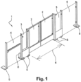
- a landing door 1 comprises, here, from one end to the other, a first emergency door 4, a first fixed part 3, a first sliding leaf 2 associated with the first fixed part 3, a second sliding leaf 2, a second fixed part 3 associated with the second sliding leaf 2, and a second emergency door 4.
- the first and second emergency doors 4 may be fixed panels.
- a door threshold 6 separates the two fixed parts 3 from each other and delimits with it an opening adjacent to the fixed access parts 3.
- the first and second sliding leaves are mounted movable in horizontal translation in the plane of the sliding leaf on the fixed part 3 associated with them via a guidance and support system 8 according to the invention.
- each sliding leaf can take a closed position in which it at least partially obstructs the adjacent opening and an open position in which it at least partially clears the aforementioned adjacent opening.
- the two sliding leaves are driven by symmetrical and, preferably, synchronized translation movements.
- the guidance and support system 8 is positioned, here, in the lower part of the landing door, and therefore of the fixed part 3 and of the sliding leaf 2 that it connects.
- the motorization mechanism of the sliding leaves 2 is also located in this lower part.
- the guidance and support system 8 and/or the motorization mechanism can be located at any part of the landing door and therefore of the fixed part 3 and of the associated sliding leaf 2.
- the first guide and support system 8 allows the mounting of the first sliding leaf 2 on the first fixed part 3 of the landing door 1 and the second guide and support system 8' according to the invention allows the second sliding leaf 2 to be mounted on the second fixed part 3 of the landing door 1.
- the two guide and support systems 8 and 8' according to the invention are mirror symmetrical.
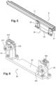
- the first guide and support system 8 according to the invention comprises a rail 11 and a rail support 20.
- the second guide and support system 8' according to the invention comprises a second rail 12 and a second rail support 30.
- the rails 11 and 12 are, here, identical and the rail supports 20, 30 are mirror symmetrical.
- the rail is a profile and is fixed to the sliding leaf 2.
- the rail 11 is, here illustrated, generally rectangular in shape. Alternatively, other shapes are possible. It therefore comprises, here, an upper wall 115, an external side wall (on the right in the figure 7 ) connected to the upper wall 115.
- the rail 11 comprises a lower wall 118 connected on a lateral edge to the external lateral wall 116.
- the lower wall 118 comprises a lower bearing surface 1181 and an upper bearing surface 1182.
- the rail 11 further comprises an internal lateral wall 117 (on the left in the figure 7 ) connected by an upper edge to the upper wall 115.
- the internal side wall 117 extends vertically only over an upper portion of a height of the section of the rail 11.
- the internal side walls 117 and lower 118 not being directly connected to each other, they define a longitudinal opening allowing the rail 11 to interface with a rail support 20.
- the rail support 20 comprises a plate 23 forming a base for fixing the rail support 20 to the platform nose. It comprises a first pillar 22 fixed to the plate 23 and extending vertically from the latter. On one side of the first pillar 22, the rail support comprises a main roller 221 mounted freely to rotate on the first pillar 22 along an axis of rotation perpendicular to a plane of the sliding leaf 2, here horizontal. On the other hand, the first pillar 22 comprises, at a top, a first pair of rollers 225 mounted mobile to rotate on the first pillar 22 along a vertical axis of rotation. The first pair of rollers 225 is positioned at the level of the main roller 221, to the right of it, here.
- the rail support 20 comprises a second pillar 21 fixed to the plate 23, at a distance from the first pillar 22, and extending vertically from the latter.
- the rail support comprises first 211 and second 212 secondary rollers mounted free to rotate on the second pillar 21 along an axis of rotation perpendicular to a plane of the sliding leaf 2, here horizontal.
- the second secondary roller 212 is positioned at a distance, vertically, from the first secondary roller 211 so that a distance e between a high point of a rolling surface of the first roller 211 and a low point of a rolling surface of the second secondary roller 212 is equivalent to a thickness of the lower wall 118 of the rail 11, with a functional clearance.
- the upper bearing surface 1182 of the lower wall 118 of the rail 11 comes to bear on the second secondary roller 212
- the lower bearing surface 1181 of the lower wall 118 of the rail 11 comes to bear on the first secondary roller 211.
- the second secondary roller 212 is offset from the first secondary roller 211 so that the second secondary roller 212 is located between the first secondary roller 211 and the main roller 221 in a direction of movement of the rail 11.
- the first 211 and second 212 secondary rollers are, here, in the same plane as the main roller 221. Alternatively, they are in different but parallel planes.
- the second pillar 21 comprises, at a top, a second pair of rollers 215 mounted to move in rotation on the second pillar 21 along a vertical axis of rotation.
- the second pair of rollers 215 is positioned at one of the first 211 and second 212 secondary rollers, in line with the latter, here.
- the second pair of rollers 215 is positioned in line with the first secondary roller 211.
- a first set of rollers is formed by the main roller 221 and the first 211 and second 212 secondary rollers.
- the primary role of this set of rollers is to support the sliding leaf 2 and to guide it during its passages from the closed position to the open position and vice versa.
- the main roller 221 supports twice the mass of the sliding leaf 2: for this purpose it has a diameter greater than a diameter of the secondary rollers 211, 212.
- the secondary rollers 211, 212 ensure that the sliding leaf 2 does not tilt in its plane whatever position it occupies.
- a second set of rollers is formed of the first 225 and second 215 pairs of rollers.
- the first role of this second set of rollers is to guide laterally, in a horizontal direction perpendicular to the direction of the horizontal translational movement of the sliding leaf 2, the rail 11 fixed to the sliding leaf 2. This makes it possible to take up the forces due to the pumping effect and the thrust of the crowd, or even the wind, which are applied to the sliding leaf 2.
- the guiding and support system 8 comprises fewer moving parts since the number of rollers has been reduced, in particular for the first set of rollers.
- maintenance costs are minimised, and the mechanical efficiency is close to 1, which generates energy savings.
- rollers of the first 225 and second 215 pairs of rollers can be replaced by friction pads, for example made of PTFE (for “polytetrafluoroethylene”).
- the main roller 221 can be replaced by two smaller rollers, for example similar to rollers 211 and 212. This makes it possible to standardize all the rollers used: which simplifies manufacturing and maintenance.
- an additional roller 2214 can be associated with the main roller 221 on the first pillar 22.
- the two main rollers 221 and additional roller are positioned on the first pillar 22 in a manner similar or symmetrical to the positioning of the two secondary rollers 211 and 212 on the second pillar 21. This makes it possible to prevent the leaf from tilting, in its plane, into the open position in certain situations.
- the main rollers 221 and secondary rollers 211 and 212 are herringbone-shaped rollers, rolling on a curved tread arranged on the surfaces 1181 and 1182 of the rail 11. This allows self-centering of the leaf 2 on said rollers.
- main rollers 221 and secondary rollers 211 and 212 are adjustable in position, in particular according to their axes of rotation in order to allow an adjustment of the verticality of the leaf 2 as well as the alignment of the latter relative to the other leaf 2 of the landing door 1.
- a support and guidance system 80 will now be described with reference to the figures 9 And 10 .
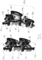
- the first set of rollers 2210, 211 and 212 of the support and guidance system 80 comprises a main roller 2210 and first 211 and second 212 secondary rollers.
- the main roller 2210 comprises, according to the invention, two rollers 2211 and 2212 positioned one behind the other in the direction of movement of the rail 1100.
- the two rollers 2211 and 2212 are identical. Furthermore, preferably but optionally, they are similar to the secondary rollers 211 and 212 in size and/or shape.
- the two rollers 2211 and 2212 are mounted, at least rotatable about their own axis, on a connecting plate 2213. This connecting plate 2213 is itself mounted rotatable on the first pillar 22.
- the first set of rollers further comprises an additional roller 2214 associated with the main roller 2210 on the first pillar 22.
- the two main rollers 2210 and additional rollers 2214 are positioned on the first pillar 22 in a manner similar or symmetrical to the positioning of the two secondary rollers 211 and 212 on the second pillar 21.
- the additional roller 2214 is located vertically to the axis of rotation of the connecting plate 2213 of the main roller 2210. This prevents the leaf from tilting in its plane into the open position in certain situations.
- the support and guidance system 80 comprises a rail 1100 of the profiled and fixed type, during assembly on the leaf 2.
- the rail 1100 comprises a first zone 1102 which is intended to cooperate with the first set of rollers 211, 212, 2210, 2214.
- the rail 1100 comprises, at the level of the first zone 1102, a tread arranged on the upper surface 1182 of convex shape, here in an arc of a circle.
- the rail 1100 further comprises a tread arranged on the lower surface 1181 of convex shape also, here, again, in an arc of a circle.
- the treads arranged on the upper surface 1182 and arranged on the lower surface 1181 are, here, mirror symmetrical with respect to each other.
- the treads arranged respectively on the upper 1182 and lower 1181 surfaces of the guide rail 1100 are inscribed in a circle, so as to perform, during operation, a pivot function with the rollers: thus, a lack of verticality of the leaf 2 does not generate any force in the rollers.
- the slide 1103, during an installation, is intended to receive slidingly, between the branches of the “U”, stop means 27 located, here, at a free end of a transmission part 26 fixed on the second pillar 21, at the level of a base of that in the vicinity of the plate 23.
- a transmission part 26 is also provided in a similar manner on the first pillar 22.
- the free end carrying the stop means 27 extends opposite and at a distance from the main roller 2210 and of the first secondary roller 211 respectively.
- An operating clearance is provided between the stop means 27 and the branches of the “U” so as to allow limited relative movement of the stop means 27 in a lateral direction within the slide 1103.
- the various rollers 211, 212, 2211, 2212 and 2214 are, here, herringbone-shaped rollers. Indeed, as illustrated in the figure 10 , a rolling surface 2112 of the secondary roller 211 has a concave cross-sectional shape that is in the form of a chevron. The same is true for a rolling surface 2122 of the other secondary roller 212.
- These rolling surfaces 2112 and 2122 come to bear and roll on curved rolling strips respectively arranged on the surfaces 1181 and 1182 of the rail 1100. This allows self-centering of the leaf 2 on said rollers as well as the possibility of transmitting lateral forces from the leaf 2 to the pillars 21 and 22.
- a lateral force when a lateral force is experienced by the leaf 2, for example following a gust of wind, a crowd push or a surge due to the passage of a train, the latter causes a lateral movement of said leaf 2.
- the lateral force is transmitted to the rail 1100 fixed on the leaf 2. Due to the shape of the rolling surfaces of the rollers of the first set of rollers cooperating with the convex treads 1181 and 1182 of the rail 1100, the lateral force is transmitted to the rollers which move in translation along their axis of rotation against the elastic limitation means 28 as long as the induced lateral movement remains less than the operating clearance between the stop means 27 and the branches of the “U” shape of the slide 1103. The lateral force is then transmitted to the pillars 21 and 22.
- each stack 28 behaves like a calibrated spring, as long as the lateral force which tends to generate a lateral displacement does not exceed the calibration value of the stacks 28, there is no lateral displacement and the stop means 27 have no role. If the lateral force increases, the calibration force is exceeded, the Belleville washers are crushed, the rollers slide on their axis, and the leaf moves laterally until the stop means 27 come to bear against one of the branches of the “U” shape of the slide 1103.
- the stop means 27 come to bear against one of the branches of the “U” shape of the slide 1103: part of the lateral force is transmitted to the pillars 21 and 22 via the rollers and the elastic limitation means 28, the other ... 21 and 22 via the stop means 27 and the transmission part 26.
- Such a structure makes it possible to protect the first set of rollers from a significant lateral force.
- such a structure also makes it possible to provide lateral guidance of the leaf 2 during a movement of the latter, which replaces the second set of rollers formed by the rollers of the first 225 and second 215 pairs of rollers of the previously described embodiment of the support and guidance system 8, 8' according to the invention.
- the various rollers 2210, 2214, 211 and 212 of the first set of rollers are adjustable in position, in particular in height.
- the axis of the rollers 211, 212, 2210 and 2214 is received respectively in an oblong, here vertical, slot 2111, 2121, 2217 and 2216 arranged in a thickness of the associated pillar 21, 22.
- Adjustment means 2110, 2120, 2215 in position within the oblong slot are provided for this purpose.
- the position adjustment means are bolts screwed into the thickness of the pillars 21, 22 and one end of which opens into the oblong slot perpendicular to the axis of the rollers and comes to bear against it.
- the guidance and support system 8 is supported, in an upper part of the fixed part 3 and of the leaf 2, by a complementary guidance system comprising a rail and sets of rollers/shoes similar in structure to the second set of rollers/shoes 215, 225. This makes it possible to reinforce the resistance to lateral forces that the leaf 2 may undergo due to wind, the pumping effect or crowd thrust.
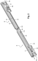
- the drive mechanism 40 comprises a drive motor 41. It is positioned, here between the pillars of the rail support 30, under the rail 12. It drives a drive pulley 42 in rotation.
- the drive mechanism comprises a first 51 and a second 52 flexible elongated drive elements.
- the flexible elongated drive elements 51 and 52 may be belts, cables or even chains.
- the flexible elongated drive elements 51, 52 are mounted in a crossed manner, the drive motor 41 directly driving only one 52 of the flexible elongated drive elements 51, 52.
- the first flexible elongated drive element 51 is fixed, at a first end 111, to a left end of the first rail 11 and, at a second end 121, to a left end of the second rail 12.
- Return pulleys 441, 442, 443, 444 make it possible to tension and define a path of the first flexible elongated drive element 51, in particular partly under the door threshold 6 so as to pass the first flexible elongated drive element 51 under the adjacent opening of the fixed parts 3 of the landing door 1 according to the invention.
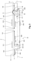
- two return pulleys 443 and 444 are located at the first fixed part 3 and two return pulleys 441, 442 are located at the second fixed part 3, as illustrated in figure 3 .
- the return pulleys 441 and 442 may be a single return pulley.
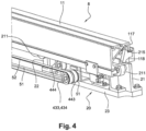
- Each pair of pulleys 443, 444 and 441 and 442 may be offset relative to each other in a horizontal direction, as is illustrated for example in figure 4 for the pair of pulleys 443,444.
- the second flexible elongated drive element 52 is fixed, at a first end 112, to a straight end of the first rail 11 and, at a second end 122, to a straight end of the second rail 12.
- return pulleys 431, 432, 433, 434 make it possible to tension and define a path of the second flexible elongated drive element 52, in particular partly under the door threshold 6 so as to pass the second flexible elongated drive element 52 under the adjacent opening of the fixed parts 3 of the landing door 1 according to the invention.
- two return pulleys 433 and 434 are located at the first fixed part 3 and two return pulleys 431, 432 are located at the second fixed part 3, as illustrated in figure 3 .
- the return pulleys 433 and 434 may be a single return pulley, as illustrated in figure 4 .
- the pulleys 431 and 432 may be a single return pulley.
- Each pair of pulleys 433, 434 and 431 and 432 may be offset relative to each other in a horizontal direction.
- the second flexible elongated drive element 52 cooperates with the drive pulley 42 to be driven by the drive motor 41.
- the two flexible elongated drive elements 51, 52 are positioned and run side by side, the set of return pulleys 431, 432, 433, 434 being axially offset from the set of return pulleys 441, 442, 443, 444.
- the section of threshold 6 is consequently very small, and therefore its footprint in the civil engineering is also very small: this facilitates the preparation of the civil engineering at the level of the platform nose and the installation of the complete platform door module 1.
- the drive pulley 42 driven by the drive motor 41 according to a rotational movement R engages the second flexible elongated drive element 52 which then moves according to a displacement D52.
- This movement D52 of the second flexible elongated drive element 52 has the effect of pulling on the end 112 of the second flexible elongated drive element 52.
- This drives the first rail 11 in a movement D11 and consequently the end 111 of the first flexible elongated drive element 51.
- the latter then performs a movement D51 along its path which has the effect of pulling on the end 121 of the first flexible elongated drive element 51.
- the second rail 12 is set in motion according to a movement D12, opposite and symmetrical to the movement D11 of the first rail 11.
- the second rail 12 then drives, in its movement D12, the end 122 of the second flexible elongated drive element 52, thus completing a drive loop formed successively by the second flexible elongated drive element 52, the first rail 11, the first flexible elongated drive element 51 and the second flexible elongated drive element 52. drive 51 and second rail 12.
- the two sliding leaves 2 are set in motion between their opening and closing positions by a single drive motor 41, while ensuring perfect synchronization between the two sliding leaves 2. This avoids the use of two motorization systems and two control systems (one for each leaf)
Landscapes
- Engineering & Computer Science (AREA)
- Mechanical Engineering (AREA)
- Transportation (AREA)
- Power-Operated Mechanisms For Wings (AREA)
- Platform Screen Doors And Railroad Systems (AREA)
- Operating, Guiding And Securing Of Roll- Type Closing Members (AREA)
Claims (19)
- Führungs- und Trägersystem (8; 80) für einen Flügel (2) einer Bahnsteigzugangstür (1), wobei sich der Flügel relativ zu einer feststehenden Platte (3) in einer horizontalen Translationsbewegung (D11, D12) in einer Ebene des Flügels zwischen einer geöffneten und einer geschlossenen Position bewegen kann, in denen der Flügel mindestens teilweise eine Öffnung angrenzend an die feststehende Platte freigibt oder versperrt, umfassend:- eine Schiene (11, 12; 1100), die zum Befestigen an dem Flügel (2) konfiguriert ist und sich in einer Richtung der horizontalen Translationsbewegung erstreckt- einen Schienenträger (20), der eine Leiste (23) aufweist, die eine Basis ausbildet, die es ermöglicht, den Schienenträger (20) an der Bahnsteigkante zu befestigen, und der einen ersten Pfeiler (22), der an der Leiste (23) befestigt ist und sich vorspringend von dieser vertikal erstreckt, und einen zweiten Pfeiler (21) aufweist, der an der Leiste (23) in einem Abstand von dem ersten Pfeiler (22) befestigt ist und sich vorspringend von dieser vertikal erstreckt,- einen ersten Rollensatz (211, 212, 2210; 2114), der mit der Schiene zum Führen davon und Tragen davon in der horizontalen Translationsbewegung zusammenwirkt, jede Rolle des Rollensatzes umfassend eine Drehachse senkrecht zu der Ebene des Flügels, wobei der erste Rollensatz besteht aus:- einer Hauptrolle (2210) in Kontakt mit einer unteren Auflageoberfläche (1181) der Schiene, wobei die Hauptrolle (2210) auf einer Seite des ersten Pfeilers (22) frei drehbar montiert ist- eine erste (211) und eine zweite (212) Sekundärrolle, die relativ zueinander in mindestens einer vertikalen Richtung versetzt sind und jeweils in Kontakt mit der unteren Auflageoberfläche (1181) der Schiene und einer oberen Auflageoberfläche (1182) der Schiene stehen, wobei die erste und die zweite Sekundärrolle in die Richtung der horizontalen Translationsbewegung und in der Richtung eines Übergangs von der geschlossenen Position in die geöffnete Position in einem Abstand von der Hauptrolle positioniert sind, wobei die erste (211) und die zweite (212) Sekundärrolle auf einer Seite des zweiten Pfeilers (21) frei drehbar montiert sind, die Hauptrolle (2210) umfassend zwei identische Rollen (2211, 2212), die in die Richtung der horizontalen Translationsbewegung hintereinander positioniert sind, wobei die zwei Rollen (2211, 2212) mindestens um ihre eigene Achse drehbar beweglich auf einer Verbindungsleiste (2213) montiert sind, wobei diese Verbindungsleiste (2213) ihrerseits drehbar beweglich auf dem ersten Pfeiler (22) montiert ist.
- System nach Anspruch 1, dadurch gekennzeichnet, dass sich die zweite Sekundärrolle (212) zwischen der Hauptrolle und der ersten Sekundärrolle (211) befindet.
- System nach einem der Ansprüche 1 bis 2,
dadurch gekennzeichnet, dass die zweite Sekundärrolle in die Richtung der horizontalen Translationsbewegung relativ zu der ersten Sekundärrolle versetzt ist. - System nach einem der Ansprüche 1 bis 3,
dadurch gekennzeichnet, dass es einen zweiten Satz Rollen/Füße (215, 225) umfasst, der dazu bestimmt ist, die Schiene in eine horizontalen Richtung senkrecht zu der Richtung der horizontalen Translationsbewegung seitlich zu führen. - System nach Anspruch 4, dadurch gekennzeichnet, dass der zweite Rollensatz ein erstes Rollenpaar (225) umfasst, das an einer (221) der Hauptrolle (2210) und einer der Sekundärrollen (211, 212) positioniert ist.
- System nach Anspruch 5, dadurch gekennzeichnet, dass der zweite Satz ein zweites Rollenpaar (215) umfasst, das an der anderen (211) der Hauptrolle (2210) und der einen der Sekundärrollen (211, 212) positioniert ist.
- System nach einem der Ansprüche 1 bis 6,
dadurch gekennzeichnet, dass der erste Rollensatz eine zusätzliche Rolle (2214) aufweist, die in Kontakt mit der oberen Auflageoberfläche (1182) der Schiene steht und vertikal zu der Drehachse der Verbindungsleiste (2213) der Hauptrolle (2210) positioniert ist. - System nach einem der Ansprüche 1 bis 7,
dadurch gekennzeichnet, dass die untere und die obere Auflageoberfläche in einen Kreis aufgenommene Laufflächen aufweisen, um eine Schwenkfunktion zwischen der Schiene und dem ersten Rollensatz auszubilden, wobei die Schiene (1100) eine erste Zone (1102) aufweist, die dazu bestimmt ist, mit dem ersten Rollensatz (211, 212, 2210, 2214) zusammenzuwirken und die eine kreisbogenförmige Lauffläche, die auf der konvexen Oberfläche (1182) angeordnet ist, und eine kreisbogenförmige Lauffläche aufweist, die auf der unteren Oberfläche (1181) angeordnet ist, wobei die unterschiedlichen Rollen (211, 212, 2211, 2212, 2214) zickzackförmige Rollen sind, die Rolloberflächen (2112, 2122) der Sekundärrollen (211, 212) im Querschnitt jeweils eine konkave Form vorweisen, die die Form eines Zickzackkörpers besitzt, wobei diese Rolloberflächen (2112, 2122) während eines Betriebs des Systems in Auflage kommen und auf geschwungenen Laufflächen rollen, die jeweils auf den Oberflächen (1181, 1182) der Schiene (1100) angeordnet sind. - System nach Anspruch 8, dadurch gekennzeichnet, dass die Schiene (1100) eine zweite Zone (1101) angrenzend an die erste Zone (1102) umfasst, an der:- die Schiene (1100) zum Befestigen an dem Flügel (2) konfiguriert ist,- die Schiene (1100) eine Gleitschiene (1103) in Form eines umgekehrten "U" umfasst, wobei sich die Gleitschiene (1103) parallel entlang einer Längsachse der Schiene (1100) erstreckt,wobei die Gleitschiene (1103) während einer Installation dazu bestimmt ist, zwischen den Schenkeln des "U" Mittel gleitend aufzunehmen, die einen Anschlag (27) ausbilden, die sich an einem freien Ende eines Übertragungsteils (26) befinden, das an dem zweiten Pfeiler (21) an einer Basis davon in der Nähe der Leiste (23) befestigt ist.
- System nach einem der Ansprüche 1 bis 9,
dadurch gekennzeichnet, dass die Rollen des ersten Rollensatzes um ihre Achse gegen elastische Begrenzungsmittel (28) translatorisch beweglich montiert sind, wobei die elastischen Begrenzungsmittel tarierte Federn ausbilden. - Bahnsteigzugangstür (1), die eine Schwelle (6), eine erste feststehende Platte (3) und einen ersten Flügel (2) aufweist, der sich relativ zu der ersten feststehenden Platte in einer horizontalen Translationsbewegung (D11, D12) in einer Ebene des Flügels zwischen der geöffneten und der geschlossenen Position bewegen kann, in der der erste Flügel eine Öffnung, die an die erste feststehende Platte angrenzt, mindestens teilweise freigibt oder versperrt,
dadurch gekennzeichnet, dass sie ein Führungs- und Trägersystem (8; 80) des ersten Flügels nach einem der Ansprüche 1 bis 10 umfasst. - Zugangstür nach Anspruch 11, dadurch gekennzeichnet, dass die Schiene (11, 12; 1100) mit dem ersten Flügel fest verbunden ist.
- Zugangstür nach einem der Ansprüche 11 bis 12,
dadurch gekennzeichnet, dass sich das Führungs- und Trägersystem in einem unteren Teil der Zugangstür befindet. - Zugangstür nach einem der Ansprüche 11 bis 13,
dadurch gekennzeichnet, dass sie aufweist:- eine zweite feststehende Platte, die durch die Öffnung und die Schwelle von der ersten feststehenden Platte getrennt ist;- einen zweiten Flügel, der sich relativ zu der zweiten feststehenden Platte in einer horizontalen Translationsbewegung (D12) in einer Ebene des Flügels zwischen der geöffneten und der geschlossenen Position bewegen kann, in denen der zweite Flügel die Öffnung teilweise freigibt oder blockiert, wobei die horizontale Translationsbewegung (D12) des zweiten Flügels symmetrisch zu der horizontalen Translationsbewegung (D11) des ersten Flügels ist; und,- ein Führungs- und Trägersystem des zweiten Flügels nach einem der Ansprüche 1 bis 10. - Zugangstür nach Anspruch 14, dadurch gekennzeichnet, dass sie einen Antriebsmechanismus (40) der Flügel umfasst, der einen Antriebsmotor (41), zwei über Kreuz befestigte längliche flexible Antriebselemente (51, 52) aufweist, wobei der Antriebsmotor nur eines (52) der zwei länglichen flexiblen Antriebselemente (51, 52) antreibt, wobei das eine (51) der länglichen flexiblen Antriebselemente zwei Enden (111, 121) aufweist, die jeweils an einem linken Ende der Schiene (11, 12) des Führungs- und Trägersystems des ersten und des zweiten Flügels befestigt sind, und das andere (52) der länglichen flexiblen Antriebselemente zwei Enden (112, 122) umfasst, die jeweils an einem rechten Ende der Schiene (11, 12) des Führungs- und Trägersystems des ersten und des zweiten Flügels befestigt sind.
- Zugangstür nach Anspruch 15, dadurch gekennzeichnet, dass die länglichen flexiblen Antriebselemente teilweise in oder unter der Schwelle verlaufen.
- Zugangstür nach Anspruch 15 oder 16, dadurch gekennzeichnet, dass die länglichen flexiblen Antriebselemente Riemen, Ketten oder Kabel sind.
- Zugangstür nach einem der Ansprüche 15 bis 17,
dadurch gekennzeichnet, dass sich der Antriebsmotor in dem unteren Teil einer der ersten und der zweiten feststehenden Platte befindet. - Zugangstür nach einem der Ansprüche 15 bis 18,
dadurch gekennzeichnet, dass der Antriebsmotor unterhalb der Schiene des Führungs- und Trägersystems einer der ersten und der zweiten feststehenden Platte positioniert ist.
Applications Claiming Priority (2)
| Application Number | Priority Date | Filing Date | Title |
|---|---|---|---|
| FR1557442A FR3039581B1 (fr) | 2015-07-31 | 2015-07-31 | Systeme de guidage et de support d'un vantail de porte paliere de quai |
| PCT/FR2016/051995 WO2017021643A1 (fr) | 2015-07-31 | 2016-07-29 | Système de guidage et de support d'un vantail de porte palière de quai |
Publications (2)
| Publication Number | Publication Date |
|---|---|
| EP3329074A1 EP3329074A1 (de) | 2018-06-06 |
| EP3329074B1 true EP3329074B1 (de) | 2024-09-25 |
Family
ID=55236458
Family Applications (1)
| Application Number | Title | Priority Date | Filing Date |
|---|---|---|---|
| EP16760128.5A Active EP3329074B1 (de) | 2015-07-31 | 2016-07-29 | System zum führen und stützen eines flügels einer plattformzugangstür |
Country Status (12)
| Country | Link |
|---|---|
| US (1) | US11242707B2 (de) |
| EP (1) | EP3329074B1 (de) |
| CN (1) | CN107849883B (de) |
| AU (1) | AU2016302023B2 (de) |
| BR (1) | BR112018001917B1 (de) |
| CA (1) | CA2992837C (de) |
| CL (1) | CL2018000284A1 (de) |
| FR (1) | FR3039581B1 (de) |
| MY (1) | MY190431A (de) |
| RU (1) | RU2018106986A (de) |
| SG (1) | SG11201800471XA (de) |
| WO (1) | WO2017021643A1 (de) |
Families Citing this family (12)
| Publication number | Priority date | Publication date | Assignee | Title |
|---|---|---|---|---|
| FR3074127B1 (fr) | 2017-11-28 | 2019-11-01 | Faiveley Transport Tours | Module de porte paliere avec un systeme de guidage haut |
| FR3074199B1 (fr) * | 2017-11-29 | 2019-11-01 | Faiveley Transport Tours | Systeme de verrouillage d'un vantail de porte paliere |
| FR3074247B1 (fr) | 2017-11-30 | 2020-03-20 | Faiveley Transport Tours | Dispositif de reglage d'une courroie pour une courroie d'entrainement de vantail de porte paliere |
| FR3074248B1 (fr) * | 2017-11-30 | 2021-06-04 | Faiveley Transp Tours | Systeme d'entrainement a courroie d'un vantail de porte-paliere de quai |
| US10946966B2 (en) * | 2018-10-29 | 2021-03-16 | B/E Aerospace, Inc. | Multi-panel privacy screen assembly |
| GB2591456B (en) * | 2020-01-22 | 2023-04-05 | Knorr Bremse Rail Systems Uk Ltd | Platform screen door |
| GB2591737B (en) * | 2020-01-22 | 2023-08-23 | Knorr Bremse Rail Systems Uk Ltd | Platform screen door |
| CN112878847B (zh) * | 2021-02-03 | 2025-10-17 | 中国铁道科学研究院集团有限公司 | 一种新型超大开度站台门 |
| CN113047717B (zh) * | 2021-03-09 | 2022-07-01 | 南京康尼机电股份有限公司 | 一种新型站台门门机机构 |
| CN113107321A (zh) * | 2021-04-29 | 2021-07-13 | 中国铁道科学研究院集团有限公司电子计算技术研究所 | 平移式站台门 |
| JP2024047330A (ja) * | 2022-09-26 | 2024-04-05 | キヤノンメディカルシステムズ株式会社 | X線診断装置 |
| CN116378525A (zh) * | 2023-04-25 | 2023-07-04 | 重庆川仪自动化股份有限公司 | 一种凹槽导轨装置及活动门 |
Family Cites Families (17)
| Publication number | Priority date | Publication date | Assignee | Title |
|---|---|---|---|---|
| US2905463A (en) * | 1956-01-06 | 1959-09-22 | Toledo Scale Corp | Elevator door carrying mechanism |
| KR920010807B1 (en) * | 1988-09-01 | 1992-12-17 | Yoshida Kogyo Kk | Sliding door opening and closing apparatus |
| DE4441152C1 (de) * | 1994-11-18 | 1995-12-21 | Juma Elementebau Gmbh U Co Kg | Schiebetor zum Verschließen einer Einfahrt |
| DE19860445A1 (de) * | 1998-12-28 | 2000-07-06 | Peter Schmid | Schiebetor |
| US6536077B1 (en) * | 2000-09-14 | 2003-03-25 | Creco Corporation | Self-lubricated wheel assembly |
| US8196353B2 (en) * | 2005-07-08 | 2012-06-12 | Ceta Elektromechanik Gmbh | Guiding mechanism for sliding leaves or sliding doors |
| TW200722606A (en) * | 2005-07-14 | 2007-06-16 | Kaba Gilgen Ag | Sliding door construction for platforms and method for assembly thereof |
| FR2902137B1 (fr) * | 2006-06-07 | 2008-08-01 | Jean Claude Fayard | Bruleur et procede pour la regeneration de cartouches de filtration et dispositifs equipes d'un tel bruleur |
| FR2903137B1 (fr) * | 2006-07-03 | 2008-10-03 | Dirickx Groupe Sa | Dispositif d'entrainement d'un vantail de portail |
| WO2008006129A1 (de) * | 2006-07-14 | 2008-01-17 | Ceta Elektromechanik Gmbh | Vorrichtung für schiebetore oder schiebetüren |
| US20090320373A1 (en) * | 2008-06-30 | 2009-12-31 | Payne Fence Products, Llc | Crash-Resistant Gate System and Method |
| JP5103354B2 (ja) * | 2008-10-30 | 2012-12-19 | 扶桑電機工業株式会社 | プラットホームの扉開閉装置 |
| JP2010188896A (ja) * | 2009-02-19 | 2010-09-02 | Nabtesco Corp | ホームドア装置 |
| US8443549B2 (en) * | 2010-03-08 | 2013-05-21 | Stanley Black & Decker, Inc. | Sliding door with large opening |
| JP5259649B2 (ja) * | 2010-05-31 | 2013-08-07 | 株式会社椿本チエイン | 噛合チェーン式ドア開閉装置 |
| KR20130049069A (ko) * | 2011-11-03 | 2013-05-13 | 주식회사 디유에이엔아이 | 난간형 스크린도어 |
| CN203361842U (zh) * | 2013-07-16 | 2013-12-25 | 法中轨道交通运输设备(上海)有限公司 | 两皮带同步传动半高安全门门机 |
-
2015
- 2015-07-31 FR FR1557442A patent/FR3039581B1/fr active Active
-
2016
- 2016-07-29 MY MYPI2018700233A patent/MY190431A/en unknown
- 2016-07-29 EP EP16760128.5A patent/EP3329074B1/de active Active
- 2016-07-29 BR BR112018001917-8A patent/BR112018001917B1/pt active IP Right Grant
- 2016-07-29 CN CN201680044427.9A patent/CN107849883B/zh active Active
- 2016-07-29 RU RU2018106986A patent/RU2018106986A/ru unknown
- 2016-07-29 WO PCT/FR2016/051995 patent/WO2017021643A1/fr not_active Ceased
- 2016-07-29 AU AU2016302023A patent/AU2016302023B2/en active Active
- 2016-07-29 US US15/746,696 patent/US11242707B2/en active Active
- 2016-07-29 SG SG11201800471XA patent/SG11201800471XA/en unknown
- 2016-07-29 CA CA2992837A patent/CA2992837C/fr active Active
-
2018
- 2018-01-31 CL CL2018000284A patent/CL2018000284A1/es unknown
Also Published As
| Publication number | Publication date |
|---|---|
| CL2018000284A1 (es) | 2018-06-22 |
| AU2016302023B2 (en) | 2021-09-16 |
| CN107849883A (zh) | 2018-03-27 |
| EP3329074A1 (de) | 2018-06-06 |
| CA2992837A1 (fr) | 2017-02-09 |
| WO2017021643A1 (fr) | 2017-02-09 |
| FR3039581B1 (fr) | 2017-07-28 |
| RU2018106986A3 (de) | 2019-10-14 |
| MY190431A (en) | 2022-04-21 |
| BR112018001917A2 (pt) | 2018-09-25 |
| CN107849883B (zh) | 2020-03-24 |
| RU2018106986A (ru) | 2019-08-29 |
| CA2992837C (fr) | 2023-10-03 |
| BR112018001917B1 (pt) | 2022-08-16 |
| AU2016302023A1 (en) | 2018-02-22 |
| US11242707B2 (en) | 2022-02-08 |
| US20180216394A1 (en) | 2018-08-02 |
| SG11201800471XA (en) | 2018-02-27 |
| FR3039581A1 (fr) | 2017-02-03 |
Similar Documents
| Publication | Publication Date | Title |
|---|---|---|
| EP3329074B1 (de) | System zum führen und stützen eines flügels einer plattformzugangstür | |
| EP2781424B1 (de) | Schienenfahrzeugwagen, der ein Zugangssystem umfasst | |
| FR2925565A1 (fr) | Procede et dispositif de mecanisation et de motorisation de persiennes coulissantes | |
| FR3041929A1 (fr) | Procede et systeme d'ouverture de porte de secours d'avion | |
| EP3115525A1 (de) | Verstellbare und isolierende blende für eine sonnenschutzanlage | |
| EP2844817B1 (de) | Schliess- oder sonnenschutzeinrichtung und verfahren zur realisierung eine der einrichtungen | |
| FR3072353A1 (fr) | Marchepied pour un vehicule ferroviaire, systeme de porte, vehicule ferroviaire et procede associes | |
| EP2635759B1 (de) | Jalousierbarer rollladen | |
| EP3445628B1 (de) | Kabeltransporteinrichtung | |
| EP4039929B1 (de) | Rollvorrichtung für schiebeflügel einer tür oder eines fensters | |
| EP3717328B1 (de) | System zum verriegeln eines flügels einer schachttür | |
| EP3176356A2 (de) | Schliessvorrichtung | |
| FR3051821A1 (fr) | Porte sectionnelle comportant un portillon et un dispositif mecanique de securite passif visant a empecher et/ou limiter l'ouverture du portillon en position ouverte du vantail d'une telle porte. | |
| EP2118418B1 (de) | Scharniersystem für ein sektionaltor, sektionaltor und befestigungsverfahren dafür | |
| FR3074127B1 (fr) | Module de porte paliere avec un systeme de guidage haut | |
| FR2739128A1 (fr) | Ouvrant coulissant a au moins deux vantaux pour porte ou fenetre | |
| FR3074248A1 (fr) | Systeme d'entrainement a courroie d'un vantail de porte-paliere de quai | |
| FR2795439A1 (fr) | Dispositif coulissant d'ouverture pour glissiere de securite | |
| WO2019106247A1 (fr) | Dispositif de reglage d'une courroie pour une courroie d'entrainement de vantail de porte paliere | |
| FR3085703A1 (fr) | Porte de garage basculante sans debord et sans rail au plafond | |
| FR3076791A1 (fr) | Porte a emprise reduite pour vehicule de transport, cloison coupe-feu et vehicule ainsi equipes | |
| EP2617922A1 (de) | Kipptorvorrichtung mit Kippassistenzfunktion | |
| FR3060464A1 (fr) | Dispositif et procede d'entrainement d'un cable de traction pour le transport de vehicules, et installation comprenant un tel dispositif | |
| FR3028549A1 (fr) | Dispositif de montage d'une porte basculante pour obturer a volonte une ouverture d'un abri | |
| FR2829172A1 (fr) | Dispositif de fermeture du type repliable en accordeon |
Legal Events
| Date | Code | Title | Description |
|---|---|---|---|
| STAA | Information on the status of an ep patent application or granted ep patent |
Free format text: STATUS: THE INTERNATIONAL PUBLICATION HAS BEEN MADE |
|
| PUAI | Public reference made under article 153(3) epc to a published international application that has entered the european phase |
Free format text: ORIGINAL CODE: 0009012 |
|
| STAA | Information on the status of an ep patent application or granted ep patent |
Free format text: STATUS: REQUEST FOR EXAMINATION WAS MADE |
|
| 17P | Request for examination filed |
Effective date: 20180115 |
|
| AK | Designated contracting states |
Kind code of ref document: A1 Designated state(s): AL AT BE BG CH CY CZ DE DK EE ES FI FR GB GR HR HU IE IS IT LI LT LU LV MC MK MT NL NO PL PT RO RS SE SI SK SM TR |
|
| AX | Request for extension of the european patent |
Extension state: BA ME |
|
| DAV | Request for validation of the european patent (deleted) | ||
| DAX | Request for extension of the european patent (deleted) | ||
| STAA | Information on the status of an ep patent application or granted ep patent |
Free format text: STATUS: EXAMINATION IS IN PROGRESS |
|
| 17Q | First examination report despatched |
Effective date: 20210528 |
|
| P01 | Opt-out of the competence of the unified patent court (upc) registered |
Effective date: 20230530 |
|
| GRAP | Despatch of communication of intention to grant a patent |
Free format text: ORIGINAL CODE: EPIDOSNIGR1 |
|
| STAA | Information on the status of an ep patent application or granted ep patent |
Free format text: STATUS: GRANT OF PATENT IS INTENDED |
|
| RIC1 | Information provided on ipc code assigned before grant |
Ipc: B61B 1/02 20060101ALI20240425BHEP Ipc: E05F 15/643 20150101ALI20240425BHEP Ipc: E05D 15/06 20060101AFI20240425BHEP |
|
| INTG | Intention to grant announced |
Effective date: 20240514 |
|
| RAP3 | Party data changed (applicant data changed or rights of an application transferred) |
Owner name: FAIVELEY TRANSPORT TOURS |
|
| GRAS | Grant fee paid |
Free format text: ORIGINAL CODE: EPIDOSNIGR3 |
|
| GRAA | (expected) grant |
Free format text: ORIGINAL CODE: 0009210 |
|
| STAA | Information on the status of an ep patent application or granted ep patent |
Free format text: STATUS: THE PATENT HAS BEEN GRANTED |
|
| AK | Designated contracting states |
Kind code of ref document: B1 Designated state(s): AL AT BE BG CH CY CZ DE DK EE ES FI FR GB GR HR HU IE IS IT LI LT LU LV MC MK MT NL NO PL PT RO RS SE SI SK SM TR |
|
| REG | Reference to a national code |
Ref country code: GB Ref legal event code: FG4D Free format text: NOT ENGLISH |
|
| REG | Reference to a national code |
Ref country code: CH Ref legal event code: EP |
|
| REG | Reference to a national code |
Ref country code: DE Ref legal event code: R096 Ref document number: 602016089558 Country of ref document: DE |
|
| REG | Reference to a national code |
Ref country code: IE Ref legal event code: FG4D Free format text: LANGUAGE OF EP DOCUMENT: FRENCH |
|
| REG | Reference to a national code |
Ref country code: LT Ref legal event code: MG9D |
|
| PG25 | Lapsed in a contracting state [announced via postgrant information from national office to epo] |
Ref country code: NO Free format text: LAPSE BECAUSE OF FAILURE TO SUBMIT A TRANSLATION OF THE DESCRIPTION OR TO PAY THE FEE WITHIN THE PRESCRIBED TIME-LIMIT Effective date: 20241225 |
|
| PG25 | Lapsed in a contracting state [announced via postgrant information from national office to epo] |
Ref country code: GR Free format text: LAPSE BECAUSE OF FAILURE TO SUBMIT A TRANSLATION OF THE DESCRIPTION OR TO PAY THE FEE WITHIN THE PRESCRIBED TIME-LIMIT Effective date: 20241226 Ref country code: FI Free format text: LAPSE BECAUSE OF FAILURE TO SUBMIT A TRANSLATION OF THE DESCRIPTION OR TO PAY THE FEE WITHIN THE PRESCRIBED TIME-LIMIT Effective date: 20240925 |
|
| PG25 | Lapsed in a contracting state [announced via postgrant information from national office to epo] |
Ref country code: BG Free format text: LAPSE BECAUSE OF FAILURE TO SUBMIT A TRANSLATION OF THE DESCRIPTION OR TO PAY THE FEE WITHIN THE PRESCRIBED TIME-LIMIT Effective date: 20240925 |
|
| PG25 | Lapsed in a contracting state [announced via postgrant information from national office to epo] |
Ref country code: LV Free format text: LAPSE BECAUSE OF FAILURE TO SUBMIT A TRANSLATION OF THE DESCRIPTION OR TO PAY THE FEE WITHIN THE PRESCRIBED TIME-LIMIT Effective date: 20240925 |
|
| PG25 | Lapsed in a contracting state [announced via postgrant information from national office to epo] |
Ref country code: RS Free format text: LAPSE BECAUSE OF FAILURE TO SUBMIT A TRANSLATION OF THE DESCRIPTION OR TO PAY THE FEE WITHIN THE PRESCRIBED TIME-LIMIT Effective date: 20241225 |
|
| REG | Reference to a national code |
Ref country code: NL Ref legal event code: MP Effective date: 20240925 |
|
| PG25 | Lapsed in a contracting state [announced via postgrant information from national office to epo] |
Ref country code: RS Free format text: LAPSE BECAUSE OF FAILURE TO SUBMIT A TRANSLATION OF THE DESCRIPTION OR TO PAY THE FEE WITHIN THE PRESCRIBED TIME-LIMIT Effective date: 20241225 Ref country code: NO Free format text: LAPSE BECAUSE OF FAILURE TO SUBMIT A TRANSLATION OF THE DESCRIPTION OR TO PAY THE FEE WITHIN THE PRESCRIBED TIME-LIMIT Effective date: 20241225 Ref country code: LV Free format text: LAPSE BECAUSE OF FAILURE TO SUBMIT A TRANSLATION OF THE DESCRIPTION OR TO PAY THE FEE WITHIN THE PRESCRIBED TIME-LIMIT Effective date: 20240925 Ref country code: GR Free format text: LAPSE BECAUSE OF FAILURE TO SUBMIT A TRANSLATION OF THE DESCRIPTION OR TO PAY THE FEE WITHIN THE PRESCRIBED TIME-LIMIT Effective date: 20241226 Ref country code: FI Free format text: LAPSE BECAUSE OF FAILURE TO SUBMIT A TRANSLATION OF THE DESCRIPTION OR TO PAY THE FEE WITHIN THE PRESCRIBED TIME-LIMIT Effective date: 20240925 Ref country code: BG Free format text: LAPSE BECAUSE OF FAILURE TO SUBMIT A TRANSLATION OF THE DESCRIPTION OR TO PAY THE FEE WITHIN THE PRESCRIBED TIME-LIMIT Effective date: 20240925 |
|
| REG | Reference to a national code |
Ref country code: AT Ref legal event code: MK05 Ref document number: 1726756 Country of ref document: AT Kind code of ref document: T Effective date: 20240925 |
|
| PG25 | Lapsed in a contracting state [announced via postgrant information from national office to epo] |
Ref country code: NL Free format text: LAPSE BECAUSE OF FAILURE TO SUBMIT A TRANSLATION OF THE DESCRIPTION OR TO PAY THE FEE WITHIN THE PRESCRIBED TIME-LIMIT Effective date: 20240925 |
|
| PG25 | Lapsed in a contracting state [announced via postgrant information from national office to epo] |
Ref country code: PT Free format text: LAPSE BECAUSE OF FAILURE TO SUBMIT A TRANSLATION OF THE DESCRIPTION OR TO PAY THE FEE WITHIN THE PRESCRIBED TIME-LIMIT Effective date: 20250127 Ref country code: IS Free format text: LAPSE BECAUSE OF FAILURE TO SUBMIT A TRANSLATION OF THE DESCRIPTION OR TO PAY THE FEE WITHIN THE PRESCRIBED TIME-LIMIT Effective date: 20250125 |
|
| PG25 | Lapsed in a contracting state [announced via postgrant information from national office to epo] |
Ref country code: RO Free format text: LAPSE BECAUSE OF FAILURE TO SUBMIT A TRANSLATION OF THE DESCRIPTION OR TO PAY THE FEE WITHIN THE PRESCRIBED TIME-LIMIT Effective date: 20240925 Ref country code: SM Free format text: LAPSE BECAUSE OF FAILURE TO SUBMIT A TRANSLATION OF THE DESCRIPTION OR TO PAY THE FEE WITHIN THE PRESCRIBED TIME-LIMIT Effective date: 20240925 |
|
| PG25 | Lapsed in a contracting state [announced via postgrant information from national office to epo] |
Ref country code: ES Free format text: LAPSE BECAUSE OF FAILURE TO SUBMIT A TRANSLATION OF THE DESCRIPTION OR TO PAY THE FEE WITHIN THE PRESCRIBED TIME-LIMIT Effective date: 20240925 |
|
| PG25 | Lapsed in a contracting state [announced via postgrant information from national office to epo] |
Ref country code: EE Free format text: LAPSE BECAUSE OF FAILURE TO SUBMIT A TRANSLATION OF THE DESCRIPTION OR TO PAY THE FEE WITHIN THE PRESCRIBED TIME-LIMIT Effective date: 20240925 Ref country code: AT Free format text: LAPSE BECAUSE OF FAILURE TO SUBMIT A TRANSLATION OF THE DESCRIPTION OR TO PAY THE FEE WITHIN THE PRESCRIBED TIME-LIMIT Effective date: 20240925 |
|
| PG25 | Lapsed in a contracting state [announced via postgrant information from national office to epo] |
Ref country code: CZ Free format text: LAPSE BECAUSE OF FAILURE TO SUBMIT A TRANSLATION OF THE DESCRIPTION OR TO PAY THE FEE WITHIN THE PRESCRIBED TIME-LIMIT Effective date: 20240925 Ref country code: PL Free format text: LAPSE BECAUSE OF FAILURE TO SUBMIT A TRANSLATION OF THE DESCRIPTION OR TO PAY THE FEE WITHIN THE PRESCRIBED TIME-LIMIT Effective date: 20240925 |
|
| PG25 | Lapsed in a contracting state [announced via postgrant information from national office to epo] |
Ref country code: SK Free format text: LAPSE BECAUSE OF FAILURE TO SUBMIT A TRANSLATION OF THE DESCRIPTION OR TO PAY THE FEE WITHIN THE PRESCRIBED TIME-LIMIT Effective date: 20240925 Ref country code: IT Free format text: LAPSE BECAUSE OF FAILURE TO SUBMIT A TRANSLATION OF THE DESCRIPTION OR TO PAY THE FEE WITHIN THE PRESCRIBED TIME-LIMIT Effective date: 20240925 |
|
| REG | Reference to a national code |
Ref country code: DE Ref legal event code: R097 Ref document number: 602016089558 Country of ref document: DE |
|
| PG25 | Lapsed in a contracting state [announced via postgrant information from national office to epo] |
Ref country code: DK Free format text: LAPSE BECAUSE OF FAILURE TO SUBMIT A TRANSLATION OF THE DESCRIPTION OR TO PAY THE FEE WITHIN THE PRESCRIBED TIME-LIMIT Effective date: 20240925 |
|
| PLBE | No opposition filed within time limit |
Free format text: ORIGINAL CODE: 0009261 |
|
| STAA | Information on the status of an ep patent application or granted ep patent |
Free format text: STATUS: NO OPPOSITION FILED WITHIN TIME LIMIT |
|
| 26N | No opposition filed |
Effective date: 20250626 |
|
| PG25 | Lapsed in a contracting state [announced via postgrant information from national office to epo] |
Ref country code: SE Free format text: LAPSE BECAUSE OF FAILURE TO SUBMIT A TRANSLATION OF THE DESCRIPTION OR TO PAY THE FEE WITHIN THE PRESCRIBED TIME-LIMIT Effective date: 20240925 |
|
| PG25 | Lapsed in a contracting state [announced via postgrant information from national office to epo] |
Ref country code: HR Free format text: LAPSE BECAUSE OF FAILURE TO SUBMIT A TRANSLATION OF THE DESCRIPTION OR TO PAY THE FEE WITHIN THE PRESCRIBED TIME-LIMIT Effective date: 20240925 |
|
| REG | Reference to a national code |
Ref country code: DE Ref legal event code: R119 Ref document number: 602016089558 Country of ref document: DE |
|
| REG | Reference to a national code |
Ref country code: CH Ref legal event code: H13 Free format text: ST27 STATUS EVENT CODE: U-0-0-H10-H13 (AS PROVIDED BY THE NATIONAL OFFICE) Effective date: 20260224 |
|
| PG25 | Lapsed in a contracting state [announced via postgrant information from national office to epo] |
Ref country code: LU Free format text: LAPSE BECAUSE OF NON-PAYMENT OF DUE FEES Effective date: 20250729 |
|
| GBPC | Gb: european patent ceased through non-payment of renewal fee |
Effective date: 20250729 |
|
| REG | Reference to a national code |
Ref country code: BE Ref legal event code: MM Effective date: 20250731 |
|
| PG25 | Lapsed in a contracting state [announced via postgrant information from national office to epo] |
Ref country code: GB Free format text: LAPSE BECAUSE OF NON-PAYMENT OF DUE FEES Effective date: 20250729 |
|
| PG25 | Lapsed in a contracting state [announced via postgrant information from national office to epo] |
Ref country code: DE Free format text: LAPSE BECAUSE OF NON-PAYMENT OF DUE FEES Effective date: 20260203 |
|
| PG25 | Lapsed in a contracting state [announced via postgrant information from national office to epo] |
Ref country code: BE Free format text: LAPSE BECAUSE OF NON-PAYMENT OF DUE FEES Effective date: 20250731 |
|
| PG25 | Lapsed in a contracting state [announced via postgrant information from national office to epo] |
Ref country code: FR Free format text: LAPSE BECAUSE OF NON-PAYMENT OF DUE FEES Effective date: 20250731 |
|
| PG25 | Lapsed in a contracting state [announced via postgrant information from national office to epo] |
Ref country code: CH Free format text: LAPSE BECAUSE OF NON-PAYMENT OF DUE FEES Effective date: 20250731 |