EP3328565B1 - Meule de cylindre destinee a l'evitement cible de quarts d'onde - Google Patents
Meule de cylindre destinee a l'evitement cible de quarts d'onde Download PDFInfo
- Publication number
- EP3328565B1 EP3328565B1 EP16721836.1A EP16721836A EP3328565B1 EP 3328565 B1 EP3328565 B1 EP 3328565B1 EP 16721836 A EP16721836 A EP 16721836A EP 3328565 B1 EP3328565 B1 EP 3328565B1
- Authority
- EP
- European Patent Office
- Prior art keywords
- rolls
- work
- contour
- work rolls
- roll stand
- Prior art date
- Legal status (The legal status is an assumption and is not a legal conclusion. Google has not performed a legal analysis and makes no representation as to the accuracy of the status listed.)
- Active
Links
Images


Classifications
-
- B—PERFORMING OPERATIONS; TRANSPORTING
- B21—MECHANICAL METAL-WORKING WITHOUT ESSENTIALLY REMOVING MATERIAL; PUNCHING METAL
- B21B—ROLLING OF METAL
- B21B31/00—Rolling stand structures; Mounting, adjusting, or interchanging rolls, roll mountings, or stand frames
- B21B31/16—Adjusting or positioning rolls
- B21B31/18—Adjusting or positioning rolls by moving rolls axially
-
- B—PERFORMING OPERATIONS; TRANSPORTING
- B21—MECHANICAL METAL-WORKING WITHOUT ESSENTIALLY REMOVING MATERIAL; PUNCHING METAL
- B21B—ROLLING OF METAL
- B21B13/00—Metal-rolling stands, i.e. an assembly composed of a stand frame, rolls, and accessories
- B21B13/14—Metal-rolling stands, i.e. an assembly composed of a stand frame, rolls, and accessories having counter-pressure devices acting on rolls to inhibit deflection of same under load; Back-up rolls
- B21B13/142—Metal-rolling stands, i.e. an assembly composed of a stand frame, rolls, and accessories having counter-pressure devices acting on rolls to inhibit deflection of same under load; Back-up rolls by axially shifting the rolls, e.g. rolls with tapered ends or with a curved contour for continuously-variable crown CVC
-
- B—PERFORMING OPERATIONS; TRANSPORTING
- B21—MECHANICAL METAL-WORKING WITHOUT ESSENTIALLY REMOVING MATERIAL; PUNCHING METAL
- B21B—ROLLING OF METAL
- B21B2267/00—Roll parameters
- B21B2267/18—Roll crown; roll profile
-
- B—PERFORMING OPERATIONS; TRANSPORTING
- B21—MECHANICAL METAL-WORKING WITHOUT ESSENTIALLY REMOVING MATERIAL; PUNCHING METAL
- B21B—ROLLING OF METAL
- B21B2267/00—Roll parameters
- B21B2267/18—Roll crown; roll profile
- B21B2267/20—Ground camber or profile
-
- B—PERFORMING OPERATIONS; TRANSPORTING
- B21—MECHANICAL METAL-WORKING WITHOUT ESSENTIALLY REMOVING MATERIAL; PUNCHING METAL
- B21B—ROLLING OF METAL
- B21B2269/00—Roll bending or shifting
- B21B2269/12—Axial shifting the rolls
Definitions
- Such a rolling mill is for example from the WO 03/022 470 A1 known.
- the contour of one of the two axially mutually displaceable rollers is formed by a first basic function, the contour of the other of the two axially mutually displaceable rollers by a second basic function.
- the basis functions are functions of the place seen in the direction of the respective axis of rotation. They are further determined such that they complement each other in the unloaded state of the two axially mutually displaceable rollers in a certain relative axial position and complementary at an outgoing from this axial position displacement Shifting direction form a convex or a concave roll gap profile.
- contour-influencing measures are the use of roll bending devices, by means of which the rolling force application to the rolling stock and the thickness distribution over the width of the rolling stock can be selectively influenced.
- the superimposition of the basic function with the additional function serves the purpose of reducing the maximum pressure acting on the work roll and the backup roll or on the intermediate roll and the backup roll, thereby increasing roll life and avoiding roll breaks as far as possible.
- the additional function is a quadratic function.
- the object of the present invention is to provide a rolling mill, in which by axial displacement of rollers, the shape of the roll gap, ie the thickness profile of the roll gap over the bale length, is varied such that a highest quality standards fulfilling, flat and wave-free rolling is achieved.
- the equivalent crown of the two axially against each other sliding rollers is provided with an offset.
- the offset is positive, only negative in exceptional cases.
- the equivalent crowning is the crowning of conventional (that is, symmetrical) ground rolls, which give the same nip profile in the unloaded or load-free state.
- the contour shift lies within the actually achievable displacement range of the two rollers which are axially displaceable relative to one another.
- the contour shift may be outside the actual reachable displacement range.
- the two basic functions always form a convex or always a concave roll gap profile independently of the actual displacement. In this case, only in the mathematical sense, a sign reversal is possible.
- the inventive design of the two axially displaceable rollers facilitates both the mathematical description of the contours of the two axially displaceable against each other Rolling as well as the manufacturing production of the contours of the two axially mutually displaceable rollers.
- the additional functions are symmetrical to one another.
- the two axially mutually displaceable rollers can be ground in the same manner and only one of the two rollers must be installed with respect to the other rotated by 180 ° in the rolling mill.
- the roll stand has no further rolls other than the work rolls.
- the work rolls are supported directly or via intermediate rolls on support rolls.
- the contours of the back-up rolls can be provided with an inverse additional contour, so that the back-up rolls complement each other in an uncompressed, unloaded state.
- the contours of the support rollers differ from those of the work rolls in particular by a concave difference.
- the contours of the intermediate rolls may be different from those of the work rolls and / or back-up rolls by such a concave difference.
- maximum pressures acting between adjoining rollers can be minimized.
- the rolling stock 2 may consist in particular of metal, for example of aluminum or steel. It can be a band or a heavy plate.
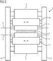
- FIG. 1 and 2 has the rolling stand 1 rolling stand 3.
- a first and a second work roll 4, 5 are mounted in the rolling mill stands 3 in the rolling mill stands 3 .
- the work rolls 4, 5 are - as is common practice - stored in the rolling mill stands 3 such that the work rolls 4, 5 about a respective axis of rotation 6, 7 are rotatable.
- the rotation is effected by means of a common drive assigned to the work rolls 4, 5 or by drives assigned to each of the work rolls 4, 5.
- the drive is or the drives are not shown in the FIG.
- the first work roll 4 is as shown in the FIG. 1 and 2 the upper work roll.
- the second work roll 5 is the lower work roll.
- the reverse assignment is also possible.
- the roll stand 1 except the work rolls 4, 5 has no further rolls (Duogerüst). In general, however, support the work rolls 4, 5, as shown in the FIG. 1 and 2 on support rollers 8, 9 from. It is according to the illustration in FIG. 1 possible that the roll stand 1 except the work rolls 4, 5 and the support rollers 8, 9 has no further rolls (for example, in a Quartogerüst). In this case, the work rolls 4, 5 are supported directly on the support rollers 8, 9. Alternatively, it is - for example, in a Sextogerüst - as shown in FIG. 2 possible that the roll stand 1 additionally intermediate rolls 10, 11 has. In this case, the work rolls 4, 5 are supported on the support rolls 8, 9 via the intermediate rolls 10, 11. The other rollers - that is, the support rollers 8, 9 and optionally also the intermediate rollers 10, 11 - are mounted in the rolling stand uprights 3, so that they are rotatable about a respective axis of rotation.
- Two of the rollers 4, 5, 8, 9, 10, 11 are mounted in the rolling stand 3 so that they are axially against each other.
- the two axially mutually displaceable rollers are the work rolls 4, 5.
- the displacement thus takes place in the direction of the axis of rotation 6, 7.
- the displaceability is in FIG. 1 indicated by corresponding double arrows at the work rolls 4, 5.
- the two axially displaceable rollers are generally the intermediate rollers 10, 11.
- the displaceability is in FIG. 2 indicated by corresponding double arrows in the intermediate rolls 10, 11.
- the work rolls 4, 5 have in this case, as a rule, a relatively small diameter and are cylindrical or (symmetrically) slightly spherical. In individual cases, however, alternatively or in addition to the intermediate rolls 10, 11, in the case of a sexto scaffolding the work rolls 4, 5 can also be axially displaceable relative to one another. In this case, the work rolls 4, 5 - optionally in addition to the intermediate rolls 10, 11 - corresponding contours.
- the two axially mutually displaceable rollers 4, 5 and 10, 11 - ie either the two work rolls 4, 5 or the two intermediate rollers 10, 11 - have according to FIG. 3 an effective bale length L on.
- the corresponding rollers 4, 5 and 10, 11 furthermore have, as from in FIG. 3 above or below the respective roller 4, 5 and 10, 11 given equations for the radius R1, R2 of the respective roller 4, 5 and 10, 11 can be seen, each having a curved contour, which extends over the entire effective bale length L extends.
- the radii R1, R2 as a function of the location x along the axes of rotation 6, 7 correspond to the contours of the rollers 4, 5 and 10, 11th
- the two axially mutually displaceable rollers 4, 5 and 10, 11 have according to FIG. 3 first on a base radius R0.
- the base radius R0 is constant, ie no function of the location x along the axis of rotation 6 of the first work roll 4 or the location x along the axis of rotation 7 of the second work roll 5 or the axes of rotation of the intermediate rolls 10, 11.
- This base radius R0 is in the case of first work roll 4 (or the first work roll 4 adjacent intermediate roll 10) superimposed on a first basis function B1, in the case of the second work roll 5 (or the second work roll 5 adjacent intermediate roll 11) has a second basic function B2.
- the basic functions B1, B2 are according to FIG. 3 Functions of the location x in the direction of the respective axis of rotation 6, 7.
- the basic functions B1, B2 are preferably, with respect to the center of the bale, antisymmetric to one another. So these are odd functions in the mathematical sense.
- the relation B1 (x) -B2 (-x) holds.
- the basic functions B1, B2 are determined so that they complement each other in the unloaded state of the respective rollers 4, 5 and 10, 11 in a certain relative axial position of the respective rollers 4, 5 and 10, 11 complementary and at one of this axial position outgoing shift depending on the direction of displacement form a convex or a concave roll gap profile.
- the meaning of these quantities is mentioned in the beginning WO 03/022 470 A1 explained.
- the reference length L Ref may be identical to the ball length L. Alternatively, it can be a different value.
- the basic functions B1, B2 are determined so that they complement each other in the unloaded state of the corresponding rollers 4, 5 and 10, 11 in a certain relative axial position of the corresponding rollers 4, 5 and 10, 11 complementary. This axial position is reached when the first work roll 4 (or the first work roll 4 adjacent intermediate roll 10) is displaced in the positive direction by the contour displacement c and the second work roll 5 (or the second work roll 5 adjacent intermediate roll 11) in negative Direction is shifted by the contour shift c.
- the basic functions B1, B2 form a convex roll gap profile.
- displacement of the first work roll 4 (or the intermediate work roll 10 adjacent to the first work roll 4) in the negative direction and, corresponding thereto, the second work roll 5 (or the intermediate work roll 11 adjacent to the second work roll 5) is positive Direction, the basic functions B1, B2 form a concave roll gap profile.
- the basic functions B1, B2 relative to the center of the bale, antisymmetric to each other.
- the first basic function B1 is additionally superimposed on an additional function Z1.
- the second basic function B2 is additionally superimposed with an additional function Z2.
- the additional functions Z1, Z2 are according to FIG. 3 - Analogous to the basic functions B1, B2 - functions of the place x in the direction of the respective axis of rotation 6, 7th
- ⁇ and ⁇ are weighting factors, which typically have a value between 0 and 2.
- the limits 0 and 2 can be assumed with. In individual cases even larger or even smaller values can be assumed.
- the weighting factors ⁇ , ⁇ can be determined independently of each other. Preferably, both weighting factors ⁇ , ⁇ have the value 1. This has the advantage that the additional functions Z1, Z2 are symmetrical to one another.
- C and D are proportional factors. As a rule, the proportion factor C has a value above zero. The proportion factor D may be 0, greater than zero, or less than zero as needed.
- the first basis function B1 is a trigonometric function superimposed on a linear function.
- the trigonometric function may in particular be a sine function.
- the sum of the additional functions Z1, Z2, however, is a polynomial function.
- the polynomial function as seen from the center of the bale and in the direction of the respective axis of rotation 6, 7, has at least a second degree component.
- the proportion factor D has a value other than 0 - the polynomial function also has a fourth degree component.
- d0 is a value which depends on the displacement s, but not on the location x in the direction of the axis of rotation 6, 7.
- the resulting course of the roll gap g has on the one hand a convex or concave portion, which is dependent on the displacement s, namely the proportion 2 ⁇ A ⁇ cos 2 ⁇ ⁇ L Ref x ⁇ sin 2 ⁇ ⁇ L Ref s - c
- the resulting course of the roll gap g has a further convex or concave portion, which is not dependent on the displacement s, namely, in the case that the proportion factor D has the value 0, the proportion 2 cx 2
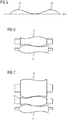
- FIG. 4 shows a similar embodiment as FIG. 3 ,
- the first basis function B1 is a polynomial function.
- the sum of the additional functions Z1, Z2 a trigonometric function.
- the trigonometric function according to FIG. 4 be a cosine function.
- ⁇ is a suitably chosen factor.
- the additional functions Z1, Z2 can be selected independently of the basis functions B1, B2.
- the additional functions Z1, Z2 are therefore not necessarily polynomial functions. It could also be trigonometric functions, in particular trigonometric functions according to FIG. 4 .
- the additional functions Z1, Z2 are not necessarily trigonometric functions. It could also be polynomial functions, in particular polynomial functions according to FIG. 3 ,
- FIG. 5 shows purely exemplary of the embodiment according to FIG. 3 the deviation of the resulting roll gap g from an average value.
- FIG. 5 it can be seen that a very uniform profile can be achieved to a considerable extent as a result of the superimposition of the basic functions B1, B2 with the additional functions Z1, Z2.
- the maxima 12 of the deviation can be further influenced both with regard to their position in the direction of the axis of rotation 6, 7 and with respect to their height.
- the present invention has many advantages.
- the adjustment range achievable by shifting the work rolls 4, 5 should be between-400 ⁇ m and -100 ⁇ m in crowning, this can be achieved by setting the adjustment range between +300 ⁇ m and +600 ⁇ m using only the basis functions B1, B2 would lie, by the additional functions Z1, Z2, however, in addition a parabolic crowning of -700 microns is superimposed.
- the superimposition of the basic functions B1, B2 and the additional functions Z1, Z2 can be used to selectively suppress edge waves as well as center waves as well as quarter waves.
- the oppression is particularly effective if not only the proportion factor C, but also the proportion factor D has a value other than 0.
Landscapes
- Engineering & Computer Science (AREA)
- Mechanical Engineering (AREA)
- Reduction Rolling/Reduction Stand/Operation Of Reduction Machine (AREA)
- Control Of Metal Rolling (AREA)
- Casting Or Compression Moulding Of Plastics Or The Like (AREA)
- Treatment Of Fiber Materials (AREA)
Claims (4)
- Cage de laminoir pour la production d'un produit de laminage plat (2), en particulier d'une bande métallique,- la cage de laminoir comprenant des montants de cage de laminoir (3),- dans laquelle des cylindres de travail (4, 5) ou des cylindres de travail (4, 5) et des cylindres d'appui (8, 9) ou des cylindres de travail (4, 5), des cylindres intermédiaires (10, 11) et des cylindres d'appui (8, 9) sont montés dans les montants de cage de laminoir (3),- dans laquelle les cylindres (4, 5, 8, 9, 10, 11) montés dans les montants de cage de laminoir (3) peuvent tourner autour d'un axe de rotation respectif (6, 7),- dans laquelle, dans le cas où des cylindres de travail (4, 5) ou des cylindres de travail (4, 5) et des cylindres d'appui (8, 9) sont montés dans les montants de cage de laminoir (3), les cylindres de travail (4, 5) peuvent se déplacer l'un par rapport à l'autre dans la direction de leur axe de rotation respectif (6, 7), c'est-à-dire axialement, et dans le cas où des cylindres de travail (4 5), des cylindres intermédiaires (10, 11) et des cylindres d'appui (8, 9) sont montés dans les montants de cage de laminoir (3), les cylindres de travail (4, 5) ou les cylindres intermédiaires (10, 11) peuvent se déplacer l'un par rapport à l'autre dans la direction de leur axe de rotation respectif (6, 7), c'est-à-dire axialement,- dans laquelle les cylindres pouvant se déplacer l'un par rapport à l'autre axialement (4, 5 resp. 10, 11) présentent respectivement une longueur de table efficace (L),- dans laquelle les cylindres pouvant se déplacer l'un par rapport à l'autre axialement (4, 5 resp. 10, 11) présentent respectivement un contour incurvé (R1, R2) qui s'étend sur toute la longueur de table efficace (L),- dans laquelle l'un des deux cylindres pouvant se déplacer l'un par rapport à l'autre axialement (4, 5 resp. 10, 11) présente un premier contour (R1) qui est formé par une superposition d'une première fonction de base (B1) et d'une première fonction supplémentaire (Z1),- dans laquelle l'autre des deux cylindres pouvant se déplacer l'un par rapport à l'autre axialement (4, 5 resp. 10, 11) présente un deuxième contour (R2) qui est formé par une superposition d'une deuxième fonction de base (B2) et d'une deuxième fonction supplémentaire (Z2),- dans laquelle les fonctions de base (B1, B2) satisfont aux relations


 - B1 et B2 sont la première et la deuxième fonction de base,- Z1 et Z2 sont la première et la deuxième fonction supplémentaire,- A et A' sont des amplitudes de contour,- ϕ est un angle de contour,- LRef est une longueur de référence,- x est le lieu resp. la position axiale, par rapport au centre de table,- c est un déplacement de contour,- B est une pente de contour,- α et β sont des facteurs de pondération,- C et D sont des facteurs de proportionnalité et- λ est un facteur.
 - Cage de laminoir selon la revendication 1,
caractérisée en ce que
les fonctions supplémentaires (Z1, Z2) sont symétriques l'une de l'autre. - Cage de laminoir selon la revendication 1 ou la revendication 2,
caractérisée
en ce que les cylindres de travail (4, 5) s'appuient directement sur des cylindres d'appui (8, 9) et en ce que les contours des cylindres d'appui (8, 9) se distinguent de ceux des cylindres de travail (4, 5) par une différence concave. - Cage de laminoir selon la revendication 1 ou la revendication 2,
caractérisée
en ce que les cylindres de travail (4, 5) s'appuient par le biais de cylindres intermédiaires (10, 11) sur des cylindres d'appui (8, 9) et en ce que les contours des cylindres intermédiaires (10, 11) se distinguent de ceux des cylindres de travail (4, 5) et/ou des cylindres d'appui (8, 9) par une différence concave.
Applications Claiming Priority (2)
| Application Number | Priority Date | Filing Date | Title |
|---|---|---|---|
| EP15178612.6A EP3124130A1 (fr) | 2015-07-28 | 2015-07-28 | Meule de cylindre destinee a l'evitement cible de quarts d'onde |
| PCT/EP2016/060724 WO2017016695A1 (fr) | 2015-07-28 | 2016-05-12 | Couronne de cylindre permettant d'éviter sélectivement les quarts d'ondes |
Publications (2)
| Publication Number | Publication Date |
|---|---|
| EP3328565A1 EP3328565A1 (fr) | 2018-06-06 |
| EP3328565B1 true EP3328565B1 (fr) | 2019-12-11 |
Family
ID=53765115
Family Applications (2)
| Application Number | Title | Priority Date | Filing Date |
|---|---|---|---|
| EP15178612.6A Withdrawn EP3124130A1 (fr) | 2015-07-28 | 2015-07-28 | Meule de cylindre destinee a l'evitement cible de quarts d'onde |
| EP16721836.1A Active EP3328565B1 (fr) | 2015-07-28 | 2016-05-12 | Meule de cylindre destinee a l'evitement cible de quarts d'onde |
Family Applications Before (1)
| Application Number | Title | Priority Date | Filing Date |
|---|---|---|---|
| EP15178612.6A Withdrawn EP3124130A1 (fr) | 2015-07-28 | 2015-07-28 | Meule de cylindre destinee a l'evitement cible de quarts d'onde |
Country Status (5)
| Country | Link |
|---|---|
| US (1) | US10589328B2 (fr) |
| EP (2) | EP3124130A1 (fr) |
| JP (1) | JP6585278B2 (fr) |
| CN (1) | CN107921496B (fr) |
| WO (1) | WO2017016695A1 (fr) |
Families Citing this family (1)
| Publication number | Priority date | Publication date | Assignee | Title |
|---|---|---|---|---|
| CN112588838B (zh) * | 2020-11-10 | 2022-04-15 | 北京科技大学 | 适用于短行程窜辊非对称自补偿轧制工作辊及其实现方法 |
Family Cites Families (25)
| Publication number | Priority date | Publication date | Assignee | Title |
|---|---|---|---|---|
| DE3038865C1 (de) * | 1980-10-15 | 1982-12-23 | SMS Schloemann-Siemag AG, 4000 Düsseldorf | Walzgeruest mit axial verschiebbaren Walzen |
| US4519233A (en) * | 1980-10-15 | 1985-05-28 | Sms Schloemann-Siemag Ag | Roll stand with noncylindrical rolls |
| DE3602698A1 (de) * | 1985-04-16 | 1986-10-16 | SMS Schloemann-Siemag AG, 4000 Düsseldorf | Walzgeruest mit axial verschiebbaren walzen |
| US4656859A (en) * | 1985-08-21 | 1987-04-14 | Wean United, Inc. | Rolling mill stand employing variable crown rolls and associated method |
| DE3620197A1 (de) | 1986-06-16 | 1987-12-17 | Schloemann Siemag Ag | Walzwerk zur herstellung eines walzgutes, insbesondere eines walzbandes |
| US5622073A (en) * | 1991-05-16 | 1997-04-22 | Kawasaki Steel Corporation | Six high rolling mill |
| JP3803761B2 (ja) | 1997-08-27 | 2006-08-02 | Jfeスチール株式会社 | 圧延機、その制御方法及び圧延形状制御方法 |
| JP2000015308A (ja) | 1998-07-08 | 2000-01-18 | Nippon Steel Corp | 圧延方法 |
| US6119500A (en) * | 1999-05-20 | 2000-09-19 | Danieli Corporation | Inverse symmetrical variable crown roll and associated method |
| AT410765B (de) | 2001-09-12 | 2003-07-25 | Voest Alpine Ind Anlagen | Walzgerüst zur herstellung von walzband |
| BRPI0402683B1 (pt) * | 2003-08-04 | 2013-12-24 | Ishikawajima Harima Heavy Ind | Laminador de chapa |
| DE10359402A1 (de) * | 2003-12-18 | 2005-07-14 | Sms Demag Ag | Optimierte Verschiebestrategien als Funktion der Bandbreite |
| DE102004020131A1 (de) * | 2003-12-19 | 2005-07-21 | Sms Demag Ag | Kombinierte Fahrweisen und Gerüsttypen in Kalttandemstraßen |
| DE102004020132A1 (de) | 2003-12-23 | 2005-07-28 | Sms Demag Ag | Verfahren und Walzgerüst zur mehrfachen Profilbeeinflussung |
| JP4645950B2 (ja) | 2005-06-30 | 2011-03-09 | 株式会社Ihi | ロールシフト圧延機 |
| CN101045240A (zh) * | 2006-03-29 | 2007-10-03 | 宝山钢铁股份有限公司 | 控制带钢边部板形的高次形轧辊 |
| US8413476B2 (en) * | 2006-06-14 | 2013-04-09 | Siemens Vai Metals Technologies Gmbh | Rolling mill stand for the production of rolled strip or sheet metal |
| JP4854602B2 (ja) | 2007-06-15 | 2012-01-18 | 株式会社神戸製鋼所 | 圧延材の形状検出方法 |
| CN101214501B (zh) * | 2007-12-27 | 2010-06-02 | 武汉钢铁(集团)公司 | 兼顾带钢凸度、边降控制和磨损控制的工作辊及使用方法 |
| CN101367092A (zh) * | 2008-10-10 | 2009-02-18 | 北京科技大学 | 一种控制冷轧钢边降的工作辊技术 |
| DE102009021414A1 (de) * | 2008-12-17 | 2010-07-01 | Sms Siemag Aktiengesellschaft | Walzgerüst zum Walzen eines insbesondere metallischen Guts |
| DE102010014867A1 (de) * | 2009-04-17 | 2010-11-18 | Sms Siemag Ag | Verfahren zum Bereitstellen mindestens einer Arbeitswalze zum Walzen eines Walzguts |
| CN101569894B (zh) | 2009-06-15 | 2010-10-27 | 北京科技大学 | 一种板带材轧制用变凸度工作辊 |
| AT509107B1 (de) | 2009-12-10 | 2011-09-15 | Siemens Vai Metals Tech Gmbh | Walzgerüst zur herstellung von walzband |
| CN102641892B (zh) * | 2012-04-28 | 2014-07-02 | 北京科技大学 | 兼顾热轧不锈钢二次和高次浪形工作辊辊形的设计方法 |
-
2015
- 2015-07-28 EP EP15178612.6A patent/EP3124130A1/fr not_active Withdrawn
-
2016
- 2016-05-12 US US15/744,158 patent/US10589328B2/en not_active Expired - Fee Related
- 2016-05-12 CN CN201680043955.2A patent/CN107921496B/zh not_active Expired - Fee Related
- 2016-05-12 WO PCT/EP2016/060724 patent/WO2017016695A1/fr active Application Filing
- 2016-05-12 JP JP2018504231A patent/JP6585278B2/ja not_active Expired - Fee Related
- 2016-05-12 EP EP16721836.1A patent/EP3328565B1/fr active Active
Non-Patent Citations (1)
| Title |
|---|
| None * |
Also Published As
| Publication number | Publication date |
|---|---|
| CN107921496B (zh) | 2019-11-01 |
| EP3124130A1 (fr) | 2017-02-01 |
| JP2018525228A (ja) | 2018-09-06 |
| US20180200769A1 (en) | 2018-07-19 |
| CN107921496A (zh) | 2018-04-17 |
| WO2017016695A1 (fr) | 2017-02-02 |
| EP3328565A1 (fr) | 2018-06-06 |
| JP6585278B2 (ja) | 2019-10-02 |
| US10589328B2 (en) | 2020-03-17 |
Similar Documents
| Publication | Publication Date | Title |
|---|---|---|
| EP1789210B1 (fr) | Cylindre convexe destine a influencer le profil et la planeite d'une bande laminee | |
| EP2026916B1 (fr) | Cage de laminoir pour la fabrication de bande laminée ou de tôle | |
| DE112005002080C5 (de) | Verfahren zum Design eines Walzenprofils und Stahlwalze mit einer in Form einer Polynomfunktion ausgedrückten Kurve des Walzenprofils | |
| DE69115746T3 (de) | Vier-Walzen-Walzwerk | |
| DE19719318C2 (de) | Verfahren zur Beeinflussung der Bandkontur im Kantenbereich eines Walzenbandes | |
| EP2379241B1 (fr) | Cage de laminoir pour laminer un produit notamment métallique | |
| DE3431691A1 (de) | Walzgeruest fuer bandfoermiges material | |
| EP1425116B1 (fr) | Cage de laminoir pour produire une bande laminee | |
| EP3253505B1 (fr) | Méthode et dispositif pour le gaufrage par laminage d' une bande | |
| EP1703999B1 (fr) | Procede et cage de laminoir pour influer de maniere multiple sur des profils | |
| EP2392416B1 (fr) | Cylindre d'appui et cage de laminoir en étant équipée | |
| EP2509723B1 (fr) | Cage de laminoir pour fabriquer du ruban de laminage | |
| EP3328565B1 (fr) | Meule de cylindre destinee a l'evitement cible de quarts d'onde | |
| EP0450294A1 (fr) | Dispositif de serrage pour ajustage d'écartement de cylindres pour laminoirs, en particulier pour laminoirs de tôles | |
| DE19812263A1 (de) | Walze für ein Walzgerüst | |
| DE102005043256A1 (de) | Konvexwalze zur Beeinflussung von Profil und Planheit eines Walzbandes | |
| EP3999259B1 (fr) | Laminage à froid du produit à laminer | |
| AT509517B1 (de) | Walzgerüst | |
| WO2000006315A1 (fr) | Cylindre d'appui ou intermediaire monte dans des laminoirs pour le laminage d'un produit plat | |
| EP0829314A1 (fr) | Palier pour rouleaux à enveloppes rigides, monté sur un axe ou un arbre |
Legal Events
| Date | Code | Title | Description |
|---|---|---|---|
| STAA | Information on the status of an ep patent application or granted ep patent |
Free format text: STATUS: THE INTERNATIONAL PUBLICATION HAS BEEN MADE |
|
| PUAI | Public reference made under article 153(3) epc to a published international application that has entered the european phase |
Free format text: ORIGINAL CODE: 0009012 |
|
| STAA | Information on the status of an ep patent application or granted ep patent |
Free format text: STATUS: REQUEST FOR EXAMINATION WAS MADE |
|
| 17P | Request for examination filed |
Effective date: 20180228 |
|
| AK | Designated contracting states |
Kind code of ref document: A1 Designated state(s): AL AT BE BG CH CY CZ DE DK EE ES FI FR GB GR HR HU IE IS IT LI LT LU LV MC MK MT NL NO PL PT RO RS SE SI SK SM TR |
|
| AX | Request for extension of the european patent |
Extension state: BA ME |
|
| DAV | Request for validation of the european patent (deleted) | ||
| DAX | Request for extension of the european patent (deleted) | ||
| GRAP | Despatch of communication of intention to grant a patent |
Free format text: ORIGINAL CODE: EPIDOSNIGR1 |
|
| STAA | Information on the status of an ep patent application or granted ep patent |
Free format text: STATUS: GRANT OF PATENT IS INTENDED |
|
| INTG | Intention to grant announced |
Effective date: 20190807 |
|
| TPAC | Observations filed by third parties |
Free format text: ORIGINAL CODE: EPIDOSNTIPA |
|
| GRAS | Grant fee paid |
Free format text: ORIGINAL CODE: EPIDOSNIGR3 |
|
| GRAA | (expected) grant |
Free format text: ORIGINAL CODE: 0009210 |
|
| STAA | Information on the status of an ep patent application or granted ep patent |
Free format text: STATUS: THE PATENT HAS BEEN GRANTED |
|
| AK | Designated contracting states |
Kind code of ref document: B1 Designated state(s): AL AT BE BG CH CY CZ DE DK EE ES FI FR GB GR HR HU IE IS IT LI LT LU LV MC MK MT NL NO PL PT RO RS SE SI SK SM TR |
|
| REG | Reference to a national code |
Ref country code: GB Ref legal event code: FG4D Free format text: NOT ENGLISH |
|
| REG | Reference to a national code |
Ref country code: CH Ref legal event code: EP |
|
| REG | Reference to a national code |
Ref country code: AT Ref legal event code: REF Ref document number: 1211681 Country of ref document: AT Kind code of ref document: T Effective date: 20191215 |
|
| REG | Reference to a national code |
Ref country code: DE Ref legal event code: R096 Ref document number: 502016007973 Country of ref document: DE |
|
| REG | Reference to a national code |
Ref country code: IE Ref legal event code: FG4D Free format text: LANGUAGE OF EP DOCUMENT: GERMAN |
|
| REG | Reference to a national code |
Ref country code: NL Ref legal event code: MP Effective date: 20191211 |
|
| REG | Reference to a national code |
Ref country code: LT Ref legal event code: MG4D |
|
| PG25 | Lapsed in a contracting state [announced via postgrant information from national office to epo] |
Ref country code: SE Free format text: LAPSE BECAUSE OF FAILURE TO SUBMIT A TRANSLATION OF THE DESCRIPTION OR TO PAY THE FEE WITHIN THE PRESCRIBED TIME-LIMIT Effective date: 20191211 Ref country code: LT Free format text: LAPSE BECAUSE OF FAILURE TO SUBMIT A TRANSLATION OF THE DESCRIPTION OR TO PAY THE FEE WITHIN THE PRESCRIBED TIME-LIMIT Effective date: 20191211 Ref country code: BG Free format text: LAPSE BECAUSE OF FAILURE TO SUBMIT A TRANSLATION OF THE DESCRIPTION OR TO PAY THE FEE WITHIN THE PRESCRIBED TIME-LIMIT Effective date: 20200311 Ref country code: GR Free format text: LAPSE BECAUSE OF FAILURE TO SUBMIT A TRANSLATION OF THE DESCRIPTION OR TO PAY THE FEE WITHIN THE PRESCRIBED TIME-LIMIT Effective date: 20200312 Ref country code: LV Free format text: LAPSE BECAUSE OF FAILURE TO SUBMIT A TRANSLATION OF THE DESCRIPTION OR TO PAY THE FEE WITHIN THE PRESCRIBED TIME-LIMIT Effective date: 20191211 Ref country code: NO Free format text: LAPSE BECAUSE OF FAILURE TO SUBMIT A TRANSLATION OF THE DESCRIPTION OR TO PAY THE FEE WITHIN THE PRESCRIBED TIME-LIMIT Effective date: 20200311 Ref country code: FI Free format text: LAPSE BECAUSE OF FAILURE TO SUBMIT A TRANSLATION OF THE DESCRIPTION OR TO PAY THE FEE WITHIN THE PRESCRIBED TIME-LIMIT Effective date: 20191211 |
|
| PG25 | Lapsed in a contracting state [announced via postgrant information from national office to epo] |
Ref country code: RS Free format text: LAPSE BECAUSE OF FAILURE TO SUBMIT A TRANSLATION OF THE DESCRIPTION OR TO PAY THE FEE WITHIN THE PRESCRIBED TIME-LIMIT Effective date: 20191211 Ref country code: HR Free format text: LAPSE BECAUSE OF FAILURE TO SUBMIT A TRANSLATION OF THE DESCRIPTION OR TO PAY THE FEE WITHIN THE PRESCRIBED TIME-LIMIT Effective date: 20191211 |
|
| PG25 | Lapsed in a contracting state [announced via postgrant information from national office to epo] |
Ref country code: AL Free format text: LAPSE BECAUSE OF FAILURE TO SUBMIT A TRANSLATION OF THE DESCRIPTION OR TO PAY THE FEE WITHIN THE PRESCRIBED TIME-LIMIT Effective date: 20191211 |
|
| PG25 | Lapsed in a contracting state [announced via postgrant information from national office to epo] |
Ref country code: CZ Free format text: LAPSE BECAUSE OF FAILURE TO SUBMIT A TRANSLATION OF THE DESCRIPTION OR TO PAY THE FEE WITHIN THE PRESCRIBED TIME-LIMIT Effective date: 20191211 Ref country code: RO Free format text: LAPSE BECAUSE OF FAILURE TO SUBMIT A TRANSLATION OF THE DESCRIPTION OR TO PAY THE FEE WITHIN THE PRESCRIBED TIME-LIMIT Effective date: 20191211 Ref country code: EE Free format text: LAPSE BECAUSE OF FAILURE TO SUBMIT A TRANSLATION OF THE DESCRIPTION OR TO PAY THE FEE WITHIN THE PRESCRIBED TIME-LIMIT Effective date: 20191211 Ref country code: PT Free format text: LAPSE BECAUSE OF FAILURE TO SUBMIT A TRANSLATION OF THE DESCRIPTION OR TO PAY THE FEE WITHIN THE PRESCRIBED TIME-LIMIT Effective date: 20200506 Ref country code: NL Free format text: LAPSE BECAUSE OF FAILURE TO SUBMIT A TRANSLATION OF THE DESCRIPTION OR TO PAY THE FEE WITHIN THE PRESCRIBED TIME-LIMIT Effective date: 20191211 Ref country code: ES Free format text: LAPSE BECAUSE OF FAILURE TO SUBMIT A TRANSLATION OF THE DESCRIPTION OR TO PAY THE FEE WITHIN THE PRESCRIBED TIME-LIMIT Effective date: 20191211 |
|
| PG25 | Lapsed in a contracting state [announced via postgrant information from national office to epo] |
Ref country code: SK Free format text: LAPSE BECAUSE OF FAILURE TO SUBMIT A TRANSLATION OF THE DESCRIPTION OR TO PAY THE FEE WITHIN THE PRESCRIBED TIME-LIMIT Effective date: 20191211 Ref country code: SM Free format text: LAPSE BECAUSE OF FAILURE TO SUBMIT A TRANSLATION OF THE DESCRIPTION OR TO PAY THE FEE WITHIN THE PRESCRIBED TIME-LIMIT Effective date: 20191211 Ref country code: IS Free format text: LAPSE BECAUSE OF FAILURE TO SUBMIT A TRANSLATION OF THE DESCRIPTION OR TO PAY THE FEE WITHIN THE PRESCRIBED TIME-LIMIT Effective date: 20200411 |
|
| REG | Reference to a national code |
Ref country code: DE Ref legal event code: R097 Ref document number: 502016007973 Country of ref document: DE |
|
| PLBE | No opposition filed within time limit |
Free format text: ORIGINAL CODE: 0009261 |
|
| STAA | Information on the status of an ep patent application or granted ep patent |
Free format text: STATUS: NO OPPOSITION FILED WITHIN TIME LIMIT |
|
| PG25 | Lapsed in a contracting state [announced via postgrant information from national office to epo] |
Ref country code: DK Free format text: LAPSE BECAUSE OF FAILURE TO SUBMIT A TRANSLATION OF THE DESCRIPTION OR TO PAY THE FEE WITHIN THE PRESCRIBED TIME-LIMIT Effective date: 20191211 |
|
| 26N | No opposition filed |
Effective date: 20200914 |
|
| PG25 | Lapsed in a contracting state [announced via postgrant information from national office to epo] |
Ref country code: SI Free format text: LAPSE BECAUSE OF FAILURE TO SUBMIT A TRANSLATION OF THE DESCRIPTION OR TO PAY THE FEE WITHIN THE PRESCRIBED TIME-LIMIT Effective date: 20191211 |
|
| PG25 | Lapsed in a contracting state [announced via postgrant information from national office to epo] |
Ref country code: LI Free format text: LAPSE BECAUSE OF NON-PAYMENT OF DUE FEES Effective date: 20200531 Ref country code: CH Free format text: LAPSE BECAUSE OF NON-PAYMENT OF DUE FEES Effective date: 20200531 Ref country code: MC Free format text: LAPSE BECAUSE OF FAILURE TO SUBMIT A TRANSLATION OF THE DESCRIPTION OR TO PAY THE FEE WITHIN THE PRESCRIBED TIME-LIMIT Effective date: 20191211 |
|
| PG25 | Lapsed in a contracting state [announced via postgrant information from national office to epo] |
Ref country code: PL Free format text: LAPSE BECAUSE OF FAILURE TO SUBMIT A TRANSLATION OF THE DESCRIPTION OR TO PAY THE FEE WITHIN THE PRESCRIBED TIME-LIMIT Effective date: 20191211 |
|
| REG | Reference to a national code |
Ref country code: BE Ref legal event code: MM Effective date: 20200531 |
|
| GBPC | Gb: european patent ceased through non-payment of renewal fee |
Effective date: 20200512 |
|
| PG25 | Lapsed in a contracting state [announced via postgrant information from national office to epo] |
Ref country code: LU Free format text: LAPSE BECAUSE OF NON-PAYMENT OF DUE FEES Effective date: 20200512 |
|
| PG25 | Lapsed in a contracting state [announced via postgrant information from national office to epo] |
Ref country code: FR Free format text: LAPSE BECAUSE OF NON-PAYMENT OF DUE FEES Effective date: 20200531 Ref country code: GB Free format text: LAPSE BECAUSE OF NON-PAYMENT OF DUE FEES Effective date: 20200512 Ref country code: IE Free format text: LAPSE BECAUSE OF NON-PAYMENT OF DUE FEES Effective date: 20200512 |
|
| PG25 | Lapsed in a contracting state [announced via postgrant information from national office to epo] |
Ref country code: BE Free format text: LAPSE BECAUSE OF NON-PAYMENT OF DUE FEES Effective date: 20200531 |
|
| PG25 | Lapsed in a contracting state [announced via postgrant information from national office to epo] |
Ref country code: TR Free format text: LAPSE BECAUSE OF FAILURE TO SUBMIT A TRANSLATION OF THE DESCRIPTION OR TO PAY THE FEE WITHIN THE PRESCRIBED TIME-LIMIT Effective date: 20191211 Ref country code: MT Free format text: LAPSE BECAUSE OF FAILURE TO SUBMIT A TRANSLATION OF THE DESCRIPTION OR TO PAY THE FEE WITHIN THE PRESCRIBED TIME-LIMIT Effective date: 20191211 Ref country code: CY Free format text: LAPSE BECAUSE OF FAILURE TO SUBMIT A TRANSLATION OF THE DESCRIPTION OR TO PAY THE FEE WITHIN THE PRESCRIBED TIME-LIMIT Effective date: 20191211 |
|
| PG25 | Lapsed in a contracting state [announced via postgrant information from national office to epo] |
Ref country code: MK Free format text: LAPSE BECAUSE OF FAILURE TO SUBMIT A TRANSLATION OF THE DESCRIPTION OR TO PAY THE FEE WITHIN THE PRESCRIBED TIME-LIMIT Effective date: 20191211 |
|
| PGFP | Annual fee paid to national office [announced via postgrant information from national office to epo] |
Ref country code: IT Payment date: 20230526 Year of fee payment: 8 Ref country code: DE Payment date: 20230519 Year of fee payment: 8 |
|
| PGFP | Annual fee paid to national office [announced via postgrant information from national office to epo] |
Ref country code: AT Payment date: 20230522 Year of fee payment: 8 |