EP3327240B1 - Haltevorrichtung zum halten einer sonnenschutzvorrichtung und haltesystem - Google Patents
Haltevorrichtung zum halten einer sonnenschutzvorrichtung und haltesystem Download PDFInfo
- Publication number
- EP3327240B1 EP3327240B1 EP17202730.2A EP17202730A EP3327240B1 EP 3327240 B1 EP3327240 B1 EP 3327240B1 EP 17202730 A EP17202730 A EP 17202730A EP 3327240 B1 EP3327240 B1 EP 3327240B1
- Authority
- EP
- European Patent Office
- Prior art keywords
- sun protection
- protection device
- holder
- holding element
- side wall
- Prior art date
- Legal status (The legal status is an assumption and is not a legal conclusion. Google has not performed a legal analysis and makes no representation as to the accuracy of the status listed.)
- Active
Links
Images


Classifications
-
- E—FIXED CONSTRUCTIONS
- E06—DOORS, WINDOWS, SHUTTERS, OR ROLLER BLINDS IN GENERAL; LADDERS
- E06B—FIXED OR MOVABLE CLOSURES FOR OPENINGS IN BUILDINGS, VEHICLES, FENCES OR LIKE ENCLOSURES IN GENERAL, e.g. DOORS, WINDOWS, BLINDS, GATES
- E06B9/00—Screening or protective devices for wall or similar openings, with or without operating or securing mechanisms; Closures of similar construction
- E06B9/24—Screens or other constructions affording protection against light, especially against sunshine; Similar screens for privacy or appearance; Slat blinds
- E06B9/40—Roller blinds
- E06B9/42—Parts or details of roller blinds, e.g. suspension devices, blind boxes
- E06B9/50—Bearings specially adapted therefor
-
- E—FIXED CONSTRUCTIONS
- E06—DOORS, WINDOWS, SHUTTERS, OR ROLLER BLINDS IN GENERAL; LADDERS
- E06B—FIXED OR MOVABLE CLOSURES FOR OPENINGS IN BUILDINGS, VEHICLES, FENCES OR LIKE ENCLOSURES IN GENERAL, e.g. DOORS, WINDOWS, BLINDS, GATES
- E06B9/00—Screening or protective devices for wall or similar openings, with or without operating or securing mechanisms; Closures of similar construction
- E06B9/24—Screens or other constructions affording protection against light, especially against sunshine; Similar screens for privacy or appearance; Slat blinds
- E06B9/26—Lamellar or like blinds, e.g. venetian blinds
- E06B9/28—Lamellar or like blinds, e.g. venetian blinds with horizontal lamellae, e.g. non-liftable
- E06B9/30—Lamellar or like blinds, e.g. venetian blinds with horizontal lamellae, e.g. non-liftable liftable
- E06B9/32—Operating, guiding, or securing devices therefor
- E06B9/323—Structure or support of upper box
Definitions
- the invention relates to a sun protection device with a holding device with two holders for mounting on side walls that delimit a light entry opening and face one another, the holders each having a contact surface for contact with the side wall and a holding element on which the sun protection device is arranged with a first orientation relative to the contact surface can.
- a fastening system for sun protection systems is from the DE 10 2005 062 995 B3 known.
- Such holding devices are used to hold sun protection devices in particular on roof windows. With these roof windows, the sun protection device is attached to the inside of the light entry opening on the window frame.
- holders are arranged in pairs on the side walls delimiting the light entry opening.
- the side wall delimiting the light-entry surface can be aligned at right angles to the light-entry opening or have an angle that deviates from 90° and is generally greater than the light-entry opening.
- a matching set of holders is usually provided for each frame geometry, ie each angle of the side wall to the light entry opening. This leads to undesirable material and storage costs and can lead to incorrect assembly when using unsuitable holders.
- the DE 10 2005 062 995 B3 solves this problem by providing a convex bearing surface on the holder, with different bores provided for different angles of the side wall. In this way, the orientation of the holder relative to the side wall is adapted to the respective angle of inclination.
- a holding device is from the U.S. 2,301,863A known.
- the holding device shown here is used to attach a sunshade to a window frame.
- the holding device consists of a hinge leaf as a contact surface for laying on the window frame and a holder for the sun protection.
- the hinge leaf and the bracket are pivotally connected to each other by means of a hinge pin.
- the sunshade is fixed to the bracket.
- the problem on which the invention is based is to reduce unnecessary storage costs for a sun protection device with a holding device of the type mentioned at the outset and to avoid incorrect assembly as far as possible, while at the same time enabling a secure and, in particular, non-pivotable arrangement of the holder on the side wall.
- the problem is solved in a sun protection device with a holding device of the type mentioned at the outset in that the holding element is at a distance from the contact surface and that the sun protection device can be arranged on the holding element with at least a second orientation to the contact surface.
- the same holder can be used for at least two frame geometries. In this way it is not necessary to change the orientation of the holder to the side wall depending on the angle of inclination thereof.
- the contact surface or the holder can be designed in such a way that good contact with the side wall is possible and, in particular, low leverage forces occur during operation of the sun protection device or when it is installed.
- a development of the invention is characterized in that the retaining element has at least one pin on which the sun protection device can be arranged in a number of orientations relative to the contact surface.
- the sun protection device can be arranged pivotably on the pin. Any angle of inclination can be realized as a result.
- the holding element can be designed as a pivot bearing.
- the holding element forms part of a joint or hinge. This gives a high Stability with simultaneous flexible use for different angles of inclination and is also easy and inexpensive to produce.
- Another development of the invention is characterized in that the holding element is provided for sliding the sun protection device on.
- mounting the sun protection device on the holder becomes particularly easy.
- the sliding of the sun protection device can be provided parallel to a pivot axis of the pivot bearing. This results in a simple construction since the required design of the means for sliding does not conflict with the required design for pivoting into the different positions for the different angles of inclination.
- An advantageous embodiment of the invention is characterized in that the holding element has fastening means for the sun protection device. This makes it particularly easy to mount the sun protection device on the holder.
- latching means and/or a hole for screwing in a screw can be provided. In both cases, easy assembly and reliable attachment of the sun protection device to the holder is possible.
- the two holders of the holding device ensure that the sun protection device is seated securely and without play in the light entry opening.
- the holder has fastening means for fastening to the side wall.
- the holder can be easily and reliably attached to the side wall.
- openings can be provided, preferably screw holes.
- the holder can easily be fastened to the side wall.
- the holder can also have a recess for a mounting part arranged on the side wall.
- Such mounting hardware is common with some skylights.
- the holder according to the invention can also be used with roof windows of this type.
- the recess forms a receptacle for the assembly part.
- this recording means that additional fastening means can be dispensed with. If the receptacle is designed for a non-positive and/or positive connection with the mounting part, a secure fit results with little assembly effort. If the contact surface is flat in a particularly preferred embodiment, a secure fit is ensured with low leverage forces.
- the invention can be used particularly advantageously as part of a sun protection system. It is advantageous here if a positioning aid is provided for the holder. In this way, the assembly at the specified position of the side wall can be reliably guaranteed.
- the positioning aid can preferably be arranged on the holding element. In this way, the position of the holding element itself, which is ultimately important when attaching the sun protection device, can be reliably ensured. It is also advantageous if the positioning aid can be attached in several orientations to the contact surface.
- the positioning aid should preferably be able to be pivotably attached to the holding element. In this way, a secure positioning of the holder can be ensured with a positioning aid and a holder, regardless of the angle of inclination of the side wall to the light entry surface.
- the positioning aid has at least one stop for positioning the holder.
- the stop is used for positioning in relation to an upper edge of the light entry opening and/or to a front side of a window reveal or a window frame. In this way, the light gaps between the sun protection device and the frame parts of the roof window can be reduced to a minimum. This ensures good sun protection.
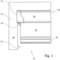
- FIG. 1 shows a schematic partial view of a sun protection device 10 as a first exemplary embodiment of the invention.
- the sun protection device 10 is arranged in a frame 12, namely a window frame 12 of a roof surface window, for shading a light entry opening 11.
- the frame 12 has the sun protection device 10 facing side walls 13, of which only one side wall 13 can be seen in the figure.
- the side walls 13 delimit the light entry opening 11 laterally.
- a holder 14 for holding the sun protection device 10 is arranged on the side wall 13 and faces the sun protection device 10 .
- the sun protection device 10 has a curtain 15 for shading the light entry opening 11 .
- a cover 16 of the sun protection device 10 is provided on the upper side of the curtain and partially covers the frame 12 .
- the cover 16 is closed off at the side by an end cap 17 .
- An end strip 18 is provided on the lower end of the hanging 15 facing away from the cover 16 .
- the end cap 17 rests against a front face 19 of the frame 12 .
- the front 19 and the side wall 13 form the in 1 shown frame 12 a right angle.
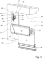
- FIG 2 shows the sunshade device 10 of FIG 1 in the state detached from the holder 14.
- the frame 12 has an upper edge 20 which 1 was covered by the cover 16.
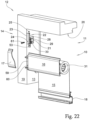
- the holder 14 has a base 21 which abuts the side wall 13. As shown in FIG. A holding element 22 is provided at a distance from the base 21 and the side wall 13 and is connected to the base 21 by means of a web 23 . As can further be seen from the figure, the web 23 has a hole 24 . By screwing a screw, not shown in the figure, into the hole 24, the sunshade device can be secured to the holder, as will be seen below with reference to FIG 22 will be explained in more detail.
- the retaining element 22 has an upper peg 25 and a lower peg 26 on ends of a body 27 that face away from one another.
- the body 27 also has a recess 28 on its longitudinal side facing away from the web 23.
- the base 21 two holes 29, 30 on.
- the holder 14 can be fastened to the frame 12 by screwing in screws (not shown in the figure) through the holes 29, 30 in the side wall 13.
- the sun protection device 10 has a winding shaft 31 onto which the curtain 15 can be wound in a known manner.
- the sun protection device 10 can be pushed onto the holding element 22 from below in the figure and secured thereto in a manner explained in more detail below.
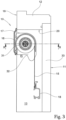
- FIG 3 12 shows a cross section of the sunshade device 10 and the frame 12 of FIG 1 .
- the sun protection device 10 has a carrier 32 which is fastened to the holder 14, as explained in more detail below.
- the cover 16 and the end cap 17 rest on the front side 19 and thus cover an upper light gap.
- the figure also shows a disc 33 on the end of the frame 12 facing away from the cover 16 .
- the curtain 15 extends approximately parallel to the pane 11 in the state shown extend down to shade the light entry opening or wind it up again on the winding shaft 31 by the spring force of a spring that is not described in detail.
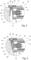
- FIG. 4 shows the section XX of 3 .
- the holder 14 bears against the side wall 13 with a contact surface 34 arranged on the side of the base 21 facing away from the holding element 22 .
- the carrier 32 has a projection 35 on its end facing away from the winding shaft 31 .
- the projection 35 is designed as a web 35 and is arranged in the recess 28 of the holding element 22 .
- the sun protection device 10 can be mounted in the frame 12 by means of the holder 14, in which the side wall 13 and the front side 19 form approximately a right angle with one another. Since the web 35 can be moved in the receptacle 28 in a hinge-like manner similar to a socket joint, the sun protection device 10 can also be fastened in the same way in other frames with the holder 14, in which the side wall 13 and the front side 19 have a larger angle than 90 degrees to each other.
- FIG 5 shows a similar representation 4 .
- the sun protection device 10 is mounted in a frame 36 by means of the holder 14 .
- the frame 36 differs from the frame 12 in that the side wall 13 and the front 19 are at an angle greater than 90 degrees to one another.
- the side wall 13 and the front 19 have an angle of 105 degrees to each other.
- this is the largest angle for which the holder 14 can be used.
- the carrier 32 comes to rest against the side wall 13 with its lower end in the figure. This is possible, although the holder 14 as well as in 4 is attached to the side wall 13 at the same angle to the latter.
- the contact surface 34 rests against the side wall 13 .
- the web 35 can be moved in the receptacle 28 like in a joint socket.
- the light gap at the side of the winding shaft 31 can continue to be covered by the end cap 17 .
- assembly in frame geometries is possible in which the angle of the side wall 13 and the front side 19 is between 90 degrees and 105 degrees.
- the height of the web 23 may have to be increased, so that a larger distance between the holding element 22 and the contact surface 34 is realized.
- FIG. 6 shows a similar representation 4 .
- a frame 37 is shown in which the side wall 13 is at an angle greater than 90 degrees to a front face 39 of the frame 37 .
- the angle between the side wall 13 and the front 39 is 95 degrees.
- a shoulder 38 is provided between the side wall 13 and the front side 39 . It can be seen from the figure that even with this angle between the side wall 13 and the front side 39 and despite the step 38, the same holder 14 can be used for mounting the sun protection device 10.
- the sun protection device 10 is mounted in a frame 40 by means of the holder 14 .
- the angle between the side wall 13 and the front 19 is 102 degrees.
- assembly with the holder 14 is possible in the same way.
- FIG. 8 shows a schematic partial representation of the frame 12 for mounting the holder 14.
- a positioning aid 41 is arranged in the upper left corner of the frame 12.
- FIG. The positioning aid has two supports 42, 43 on a handle 44 at opposite ends.
- receptacles 45, 46 for the pins 25, 26 of the holder 14 are provided on the side of the supports 42, 43 facing away from the handle.
- the pins 25, 26 are in the associated receptacles 45, 46.
- the positioning aid further has stops 47, 48 for striking against the side wall 13 and stops 49, 50 for striking against the upper edge 20 on. At the in the 8 the state shown, the stop 49 rests against the upper edge 20 .
- the stop 50 comes to rest with the upper edge 20.
- the position of the holder 14 on the side wall 13 is fixed by the rest of the supports 42, 43 on the front side 19 of the frame 12 and by the stop 49 striking the upper edge 20. Since the pins 25, 26 are in the receptacles 45, 46, a different angle between the positioning aid 41 and the holder 14 is possible with other frame geometries. In this way, the holder 14 is always reliably positioned for the respective frame geometry. After the position of the holder 14 has been determined by means of the positioning aid 41, the holder 14 can be screwed tightly to the side wall 13 through the holes 29, 30 by means of screws 51, 52.
- FIG 9 shows the holder 14 of FIG 8 after screwing the screws 51, 52 through the holes 29, 30 into the side wall 13, the positioning aid being removed from the holder 14. Because of the interaction of the stop 49 with the upper edge 20, the height of the holder 14 is correctly adjusted. Through the interaction of the supports 42, 43 with the front side 19, the spacing of the holding element 22 is in turn set correctly in such a way that the cover 16 and the end cap 17 come to rest on the front side 19.
- the holder 14 shows the positioning aid 41 in a perspective view when it has been removed from the holder 14 .
- the holder 14 also has a latching hook 53 . After sliding the sun protection device 10 onto the holding element 22 of the holder 14 , the carrier 32 snaps into the snap-in hook 53 by means of snap-in elements corresponding to the snap-in hook and is thus held securely on the holder 14 .
- the figure also shows how the receptacles 45, 46 can be plugged onto the pins 25, 26. It can also be seen that the positioning aid 41 can be pivoted about these pins 25, 26 when the receptacles 45, 46 are pushed onto the pins 25, 26.
- FIG. 11 shows a similar representation 10 from a different perspective. The figure serves to better illustrate the interaction of positioning aid 41 and holder 14.
- FIG. 12 shows a similar representation 10 .
- the positioning aid 41 is pushed onto the holder 14 in such a way that the pins 25, 26 are accommodated in the receptacles 45, 46.
- FIG. 13 shows a plan view of the positioning aid 41 and the holder 14.
- the positioning aid 41 is removed from the holder 14. The figure serves to better understand how the positioning aid works.
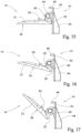
- the Figures 15 to 17 show the positioning aid 41 arranged on the holder 14 in different geometries. It can be seen from the figures that the position of the holder relative to a front of a frame increases as the angle between the side wall and the front increases. In this way, a correct positioning of the holder is achieved by means of the positioning aid at the respective angle between the side wall and the front side.
- FIG. 18 shows a perspective partial view of a frame 12. Shown is a perspective view of the upper left corner. As can be seen from the figure, the frame 12 has a mounting part 54 on the side wall 13 in its upper left corner. There are window manufacturers who provide such assembly parts 54 for the assembly of their own sun protection devices.
- FIG 19 shows the arrangement of the holder 14 in the frame 12 with mounting part 54 of FIG 18 .
- the holder 14 can also be used in the presence of such mounting parts 54, the holder 14 has a recess above its base 21.
- the base 21 comes to lie on the underside of the mounting part 54, while the web 23 is arranged on an unnumbered front side of the mounting part 54.
- the holder 14 can be positioned in the manner described and screwed to the side wall 13 by means of the screws 51, 52.
- the holder 14 can thus be used independently of the frame geometry and the presence of assembly parts 54 and can be reliably positioned by means of the positioning aid 41 .
- the 20 12 shows a holder 55 as another embodiment of the invention.
- the same elements carry the same reference numbers.
- the holder 55 has a frame 56 which encloses a recess 57.
- the dimensions of this recess 57 correspond to those of the assembly part 54.
- the holder 25 has a holding element 28 similar to the holding element 22 .
- the same elements carry the same reference numbers.
- the holding element 58 has no pins 25, 26, since positioning is effected by the mounting part 54. But it is also possible that the holding element 58 also has pins 25, 26. In this way, the holder 55 can be used with or without the mounting part 54 and with different frame geometries.
- FIG 21 shows a plan view of the side wall 13 of the holder 55 of FIG 20 .
- the frame 56 encloses the mounting part 54 in a non-positive manner.
- the holder 55 is held securely on the mounting part 54 by plugging the frame 56 onto the mounting part 54 .
- a further screw connection by means of screws 51, 52 through the holes 29, 30 is not necessary in this case.
- the cover 16 has a web 59 at its end facing the end cap 17.
- the web 59 in turn has a slot 60, the position of which corresponds to that of the hole 24 when the sun protection device 10 is pushed onto the holding element 22 .
- the sun protection device 52 is pushed onto the holding element 22 with its carrier 32 , the sun protection device 10 can be secured on the holder 24 by means of the latching hook 53 .
Landscapes
- Engineering & Computer Science (AREA)
- Structural Engineering (AREA)
- Architecture (AREA)
- Civil Engineering (AREA)
- Curtains And Furnishings For Windows Or Doors (AREA)
Applications Claiming Priority (1)
| Application Number | Priority Date | Filing Date | Title |
|---|---|---|---|
| DE102016122915.6A DE102016122915A1 (de) | 2016-11-28 | 2016-11-28 | Haltevorrichtung zum Halten einer Sonnenschutzvorrichtung und Haltesystem |
Publications (2)
| Publication Number | Publication Date |
|---|---|
| EP3327240A1 EP3327240A1 (de) | 2018-05-30 |
| EP3327240B1 true EP3327240B1 (de) | 2023-05-10 |
Family
ID=60450438
Family Applications (1)
| Application Number | Title | Priority Date | Filing Date |
|---|---|---|---|
| EP17202730.2A Active EP3327240B1 (de) | 2016-11-28 | 2017-11-21 | Haltevorrichtung zum halten einer sonnenschutzvorrichtung und haltesystem |
Country Status (4)
| Country | Link |
|---|---|
| EP (1) | EP3327240B1 (pl) |
| DE (1) | DE102016122915A1 (pl) |
| DK (1) | DK3327240T3 (pl) |
| PL (1) | PL3327240T3 (pl) |
Families Citing this family (2)
| Publication number | Priority date | Publication date | Assignee | Title |
|---|---|---|---|---|
| EP4006295B1 (en) * | 2020-11-27 | 2025-02-19 | VKR Holding A/S | A screening arrangement for a roof window, and roof window comprising such a screening arrangement |
| DE102021003122A1 (de) | 2021-06-18 | 2022-12-22 | Hunter Douglas Holding GmbH & Co. KG | Montagevorrichtung für Plisseeanlagen |
Citations (1)
| Publication number | Priority date | Publication date | Assignee | Title |
|---|---|---|---|---|
| EP3325753A1 (fr) * | 2015-07-21 | 2018-05-30 | Somfy Activites Sa | Équipement d'enroulement d'écran à attache murale articulée |
Family Cites Families (4)
| Publication number | Priority date | Publication date | Assignee | Title |
|---|---|---|---|---|
| US2301863A (en) * | 1941-01-17 | 1942-11-10 | Harry D Forse | Double roller shade support and light shield |
| AT501233B1 (de) * | 2004-12-22 | 2006-10-15 | Wo & Wo Gruen Gmbh | Kopfteil |
| DE102005062995B3 (de) | 2005-12-30 | 2007-05-16 | Warema Kunststofftechnik Und M | Befestigungssystem für Sonnenschutzanlagen |
| DK2011951T3 (da) * | 2007-07-03 | 2019-12-09 | Hunter Douglas Ind Bv | Holder sammen med og til understøtning af en afdækningsanordning |
-
2016
- 2016-11-28 DE DE102016122915.6A patent/DE102016122915A1/de not_active Ceased
-
2017
- 2017-11-21 DK DK17202730.2T patent/DK3327240T3/da active
- 2017-11-21 PL PL17202730.2T patent/PL3327240T3/pl unknown
- 2017-11-21 EP EP17202730.2A patent/EP3327240B1/de active Active
Patent Citations (1)
| Publication number | Priority date | Publication date | Assignee | Title |
|---|---|---|---|---|
| EP3325753A1 (fr) * | 2015-07-21 | 2018-05-30 | Somfy Activites Sa | Équipement d'enroulement d'écran à attache murale articulée |
Also Published As
| Publication number | Publication date |
|---|---|
| EP3327240A1 (de) | 2018-05-30 |
| PL3327240T3 (pl) | 2023-10-30 |
| DK3327240T3 (da) | 2023-07-24 |
| DE102016122915A1 (de) | 2018-05-30 |
Similar Documents
| Publication | Publication Date | Title |
|---|---|---|
| DE4219681C2 (de) | Einstellbares Abhebescharnier | |
| EP2715021B1 (de) | Scharnier | |
| DE1919146C3 (de) | Scharnier | |
| EP2331367B1 (de) | Spiegelhalterung zum befestigen eines spiegels an einem fahrzeug und spiegel mit einer solchen spiegelhalterung | |
| WO1989008180A1 (fr) | Fixation pour dispositifs antisolaires | |
| EP3327240B1 (de) | Haltevorrichtung zum halten einer sonnenschutzvorrichtung und haltesystem | |
| DE112014006955B4 (de) | Türscharnier mit höhenverstellvorrichtung für eine drehende tür | |
| EP3425155B1 (de) | Klemmschutzeinrichtung für eine tür | |
| EP2951374B1 (de) | Laufteil zum führen eines möbelteils in einer führungsrichtung über eine führungsschiene und möbelbeschlag | |
| DE4128486C2 (de) | Verschlußvorrichtung für Flügel | |
| DE102017121385A1 (de) | Blendenträger und Schubkasten | |
| DE2629727C3 (de) | Heb- und absenkbare Auflage | |
| DE102017206462B4 (de) | System zur fixierung einer abdeckung an einem gepäckbehälter | |
| DE3913319C2 (pl) | ||
| DE69808038T2 (de) | Verbesserung der gelenkigen Verbindung eines Flügels an einem Rahmen | |
| DE102022213472B3 (de) | Halterung zum Halten einer Markisenkomponente, Lagerteil zum Lagern einer Tuchwelle und Markise | |
| DE19828233A1 (de) | Wandkonsole | |
| EP2947247B1 (de) | Wohndachfenster mit verstellbarem scharnier | |
| WO2020069836A1 (de) | Befestigungsvorrichtung für eine blende eines schubkastens an einer zarge | |
| EP2589735A2 (de) | Beschlaganordnung | |
| EP3623558B1 (de) | Deckelbeschlag zum schwenkbaren befestigen eines deckels an einem möbelkorpus | |
| DE102004053989B4 (de) | Türfeststellvorrichtung | |
| DE3117118A1 (de) | Scharnier, insbesondere fuer tueren, wie tueren von sicherungs- oder schaltkaesten | |
| DE7713094U1 (de) | Griff, insbesondere haltegriff fuer fahrzeuge | |
| EP4246745A1 (de) | Leitungsauslass |
Legal Events
| Date | Code | Title | Description |
|---|---|---|---|
| PUAI | Public reference made under article 153(3) epc to a published international application that has entered the european phase |
Free format text: ORIGINAL CODE: 0009012 |
|
| STAA | Information on the status of an ep patent application or granted ep patent |
Free format text: STATUS: THE APPLICATION HAS BEEN PUBLISHED |
|
| AK | Designated contracting states |
Kind code of ref document: A1 Designated state(s): AL AT BE BG CH CY CZ DE DK EE ES FI FR GB GR HR HU IE IS IT LI LT LU LV MC MK MT NL NO PL PT RO RS SE SI SK SM TR |
|
| AX | Request for extension of the european patent |
Extension state: BA ME |
|
| STAA | Information on the status of an ep patent application or granted ep patent |
Free format text: STATUS: REQUEST FOR EXAMINATION WAS MADE |
|
| 17P | Request for examination filed |
Effective date: 20181130 |
|
| RBV | Designated contracting states (corrected) |
Designated state(s): AL AT BE BG CH CY CZ DE DK EE ES FI FR GB GR HR HU IE IS IT LI LT LU LV MC MK MT NL NO PL PT RO RS SE SI SK SM TR |
|
| STAA | Information on the status of an ep patent application or granted ep patent |
Free format text: STATUS: EXAMINATION IS IN PROGRESS |
|
| 17Q | First examination report despatched |
Effective date: 20200224 |
|
| GRAP | Despatch of communication of intention to grant a patent |
Free format text: ORIGINAL CODE: EPIDOSNIGR1 |
|
| STAA | Information on the status of an ep patent application or granted ep patent |
Free format text: STATUS: GRANT OF PATENT IS INTENDED |
|
| INTG | Intention to grant announced |
Effective date: 20220518 |
|
| GRAJ | Information related to disapproval of communication of intention to grant by the applicant or resumption of examination proceedings by the epo deleted |
Free format text: ORIGINAL CODE: EPIDOSDIGR1 |
|
| STAA | Information on the status of an ep patent application or granted ep patent |
Free format text: STATUS: EXAMINATION IS IN PROGRESS |
|
| INTC | Intention to grant announced (deleted) | ||
| GRAP | Despatch of communication of intention to grant a patent |
Free format text: ORIGINAL CODE: EPIDOSNIGR1 |
|
| STAA | Information on the status of an ep patent application or granted ep patent |
Free format text: STATUS: GRANT OF PATENT IS INTENDED |
|
| GRAS | Grant fee paid |
Free format text: ORIGINAL CODE: EPIDOSNIGR3 |
|
| GRAA | (expected) grant |
Free format text: ORIGINAL CODE: 0009210 |
|
| STAA | Information on the status of an ep patent application or granted ep patent |
Free format text: STATUS: THE PATENT HAS BEEN GRANTED |
|
| INTG | Intention to grant announced |
Effective date: 20230316 |
|
| AK | Designated contracting states |
Kind code of ref document: B1 Designated state(s): AL AT BE BG CH CY CZ DE DK EE ES FI FR GB GR HR HU IE IS IT LI LT LU LV MC MK MT NL NO PL PT RO RS SE SI SK SM TR |
|
| REG | Reference to a national code |
Ref country code: GB Ref legal event code: FG4D Free format text: NOT ENGLISH |
|
| REG | Reference to a national code |
Ref country code: AT Ref legal event code: REF Ref document number: 1566837 Country of ref document: AT Kind code of ref document: T Effective date: 20230515 Ref country code: CH Ref legal event code: EP |
|
| REG | Reference to a national code |
Ref country code: DE Ref legal event code: R096 Ref document number: 502017014700 Country of ref document: DE |
|
| REG | Reference to a national code |
Ref country code: IE Ref legal event code: FG4D Free format text: LANGUAGE OF EP DOCUMENT: GERMAN |
|
| P01 | Opt-out of the competence of the unified patent court (upc) registered |
Effective date: 20230515 |
|
| REG | Reference to a national code |
Ref country code: DK Ref legal event code: T3 Effective date: 20230720 |
|
| REG | Reference to a national code |
Ref country code: NL Ref legal event code: FP |
|
| REG | Reference to a national code |
Ref country code: LT Ref legal event code: MG9D |
|
| PG25 | Lapsed in a contracting state [announced via postgrant information from national office to epo] |
Ref country code: SE Free format text: LAPSE BECAUSE OF FAILURE TO SUBMIT A TRANSLATION OF THE DESCRIPTION OR TO PAY THE FEE WITHIN THE PRESCRIBED TIME-LIMIT Effective date: 20230510 Ref country code: PT Free format text: LAPSE BECAUSE OF FAILURE TO SUBMIT A TRANSLATION OF THE DESCRIPTION OR TO PAY THE FEE WITHIN THE PRESCRIBED TIME-LIMIT Effective date: 20230911 Ref country code: NO Free format text: LAPSE BECAUSE OF FAILURE TO SUBMIT A TRANSLATION OF THE DESCRIPTION OR TO PAY THE FEE WITHIN THE PRESCRIBED TIME-LIMIT Effective date: 20230810 Ref country code: ES Free format text: LAPSE BECAUSE OF FAILURE TO SUBMIT A TRANSLATION OF THE DESCRIPTION OR TO PAY THE FEE WITHIN THE PRESCRIBED TIME-LIMIT Effective date: 20230510 |
|
| PG25 | Lapsed in a contracting state [announced via postgrant information from national office to epo] |
Ref country code: RS Free format text: LAPSE BECAUSE OF FAILURE TO SUBMIT A TRANSLATION OF THE DESCRIPTION OR TO PAY THE FEE WITHIN THE PRESCRIBED TIME-LIMIT Effective date: 20230510 Ref country code: LV Free format text: LAPSE BECAUSE OF FAILURE TO SUBMIT A TRANSLATION OF THE DESCRIPTION OR TO PAY THE FEE WITHIN THE PRESCRIBED TIME-LIMIT Effective date: 20230510 Ref country code: LT Free format text: LAPSE BECAUSE OF FAILURE TO SUBMIT A TRANSLATION OF THE DESCRIPTION OR TO PAY THE FEE WITHIN THE PRESCRIBED TIME-LIMIT Effective date: 20230510 Ref country code: IS Free format text: LAPSE BECAUSE OF FAILURE TO SUBMIT A TRANSLATION OF THE DESCRIPTION OR TO PAY THE FEE WITHIN THE PRESCRIBED TIME-LIMIT Effective date: 20230910 Ref country code: HR Free format text: LAPSE BECAUSE OF FAILURE TO SUBMIT A TRANSLATION OF THE DESCRIPTION OR TO PAY THE FEE WITHIN THE PRESCRIBED TIME-LIMIT Effective date: 20230510 Ref country code: GR Free format text: LAPSE BECAUSE OF FAILURE TO SUBMIT A TRANSLATION OF THE DESCRIPTION OR TO PAY THE FEE WITHIN THE PRESCRIBED TIME-LIMIT Effective date: 20230811 |
|
| PG25 | Lapsed in a contracting state [announced via postgrant information from national office to epo] |
Ref country code: FI Free format text: LAPSE BECAUSE OF FAILURE TO SUBMIT A TRANSLATION OF THE DESCRIPTION OR TO PAY THE FEE WITHIN THE PRESCRIBED TIME-LIMIT Effective date: 20230510 |
|
| PG25 | Lapsed in a contracting state [announced via postgrant information from national office to epo] |
Ref country code: SK Free format text: LAPSE BECAUSE OF FAILURE TO SUBMIT A TRANSLATION OF THE DESCRIPTION OR TO PAY THE FEE WITHIN THE PRESCRIBED TIME-LIMIT Effective date: 20230510 |
|
| PG25 | Lapsed in a contracting state [announced via postgrant information from national office to epo] |
Ref country code: SM Free format text: LAPSE BECAUSE OF FAILURE TO SUBMIT A TRANSLATION OF THE DESCRIPTION OR TO PAY THE FEE WITHIN THE PRESCRIBED TIME-LIMIT Effective date: 20230510 Ref country code: SK Free format text: LAPSE BECAUSE OF FAILURE TO SUBMIT A TRANSLATION OF THE DESCRIPTION OR TO PAY THE FEE WITHIN THE PRESCRIBED TIME-LIMIT Effective date: 20230510 Ref country code: RO Free format text: LAPSE BECAUSE OF FAILURE TO SUBMIT A TRANSLATION OF THE DESCRIPTION OR TO PAY THE FEE WITHIN THE PRESCRIBED TIME-LIMIT Effective date: 20230510 Ref country code: EE Free format text: LAPSE BECAUSE OF FAILURE TO SUBMIT A TRANSLATION OF THE DESCRIPTION OR TO PAY THE FEE WITHIN THE PRESCRIBED TIME-LIMIT Effective date: 20230510 |
|
| REG | Reference to a national code |
Ref country code: DE Ref legal event code: R097 Ref document number: 502017014700 Country of ref document: DE |
|
| PLBE | No opposition filed within time limit |
Free format text: ORIGINAL CODE: 0009261 |
|
| STAA | Information on the status of an ep patent application or granted ep patent |
Free format text: STATUS: NO OPPOSITION FILED WITHIN TIME LIMIT |
|
| 26N | No opposition filed |
Effective date: 20240213 |
|
| PG25 | Lapsed in a contracting state [announced via postgrant information from national office to epo] |
Ref country code: SI Free format text: LAPSE BECAUSE OF FAILURE TO SUBMIT A TRANSLATION OF THE DESCRIPTION OR TO PAY THE FEE WITHIN THE PRESCRIBED TIME-LIMIT Effective date: 20230510 |
|
| PG25 | Lapsed in a contracting state [announced via postgrant information from national office to epo] |
Ref country code: SI Free format text: LAPSE BECAUSE OF FAILURE TO SUBMIT A TRANSLATION OF THE DESCRIPTION OR TO PAY THE FEE WITHIN THE PRESCRIBED TIME-LIMIT Effective date: 20230510 Ref country code: IT Free format text: LAPSE BECAUSE OF FAILURE TO SUBMIT A TRANSLATION OF THE DESCRIPTION OR TO PAY THE FEE WITHIN THE PRESCRIBED TIME-LIMIT Effective date: 20230510 |
|
| PG25 | Lapsed in a contracting state [announced via postgrant information from national office to epo] |
Ref country code: MC Free format text: LAPSE BECAUSE OF FAILURE TO SUBMIT A TRANSLATION OF THE DESCRIPTION OR TO PAY THE FEE WITHIN THE PRESCRIBED TIME-LIMIT Effective date: 20230510 |
|
| PG25 | Lapsed in a contracting state [announced via postgrant information from national office to epo] |
Ref country code: LU Free format text: LAPSE BECAUSE OF NON-PAYMENT OF DUE FEES Effective date: 20231121 |
|
| PG25 | Lapsed in a contracting state [announced via postgrant information from national office to epo] |
Ref country code: MC Free format text: LAPSE BECAUSE OF FAILURE TO SUBMIT A TRANSLATION OF THE DESCRIPTION OR TO PAY THE FEE WITHIN THE PRESCRIBED TIME-LIMIT Effective date: 20230510 Ref country code: LU Free format text: LAPSE BECAUSE OF NON-PAYMENT OF DUE FEES Effective date: 20231121 |
|
| REG | Reference to a national code |
Ref country code: IE Ref legal event code: MM4A |
|
| PG25 | Lapsed in a contracting state [announced via postgrant information from national office to epo] |
Ref country code: IE Free format text: LAPSE BECAUSE OF NON-PAYMENT OF DUE FEES Effective date: 20231121 |
|
| PG25 | Lapsed in a contracting state [announced via postgrant information from national office to epo] |
Ref country code: IE Free format text: LAPSE BECAUSE OF NON-PAYMENT OF DUE FEES Effective date: 20231121 |
|
| PG25 | Lapsed in a contracting state [announced via postgrant information from national office to epo] |
Ref country code: BG Free format text: LAPSE BECAUSE OF FAILURE TO SUBMIT A TRANSLATION OF THE DESCRIPTION OR TO PAY THE FEE WITHIN THE PRESCRIBED TIME-LIMIT Effective date: 20230510 |
|
| PG25 | Lapsed in a contracting state [announced via postgrant information from national office to epo] |
Ref country code: BG Free format text: LAPSE BECAUSE OF FAILURE TO SUBMIT A TRANSLATION OF THE DESCRIPTION OR TO PAY THE FEE WITHIN THE PRESCRIBED TIME-LIMIT Effective date: 20230510 |
|
| PG25 | Lapsed in a contracting state [announced via postgrant information from national office to epo] |
Ref country code: CY Free format text: LAPSE BECAUSE OF FAILURE TO SUBMIT A TRANSLATION OF THE DESCRIPTION OR TO PAY THE FEE WITHIN THE PRESCRIBED TIME-LIMIT; INVALID AB INITIO Effective date: 20171121 |
|
| PG25 | Lapsed in a contracting state [announced via postgrant information from national office to epo] |
Ref country code: HU Free format text: LAPSE BECAUSE OF FAILURE TO SUBMIT A TRANSLATION OF THE DESCRIPTION OR TO PAY THE FEE WITHIN THE PRESCRIBED TIME-LIMIT; INVALID AB INITIO Effective date: 20171121 |
|
| REG | Reference to a national code |
Ref country code: CH Ref legal event code: U11 Free format text: ST27 STATUS EVENT CODE: U-0-0-U10-U11 (AS PROVIDED BY THE NATIONAL OFFICE) Effective date: 20251201 |
|
| PG25 | Lapsed in a contracting state [announced via postgrant information from national office to epo] |
Ref country code: TR Free format text: LAPSE BECAUSE OF FAILURE TO SUBMIT A TRANSLATION OF THE DESCRIPTION OR TO PAY THE FEE WITHIN THE PRESCRIBED TIME-LIMIT Effective date: 20230510 |
|
| PGFP | Annual fee paid to national office [announced via postgrant information from national office to epo] |
Ref country code: NL Payment date: 20251124 Year of fee payment: 9 |
|
| PGFP | Annual fee paid to national office [announced via postgrant information from national office to epo] |
Ref country code: DE Payment date: 20251126 Year of fee payment: 9 |
|
| PGFP | Annual fee paid to national office [announced via postgrant information from national office to epo] |
Ref country code: GB Payment date: 20251125 Year of fee payment: 9 |
|
| PGFP | Annual fee paid to national office [announced via postgrant information from national office to epo] |
Ref country code: AT Payment date: 20251118 Year of fee payment: 9 |
|
| PGFP | Annual fee paid to national office [announced via postgrant information from national office to epo] |
Ref country code: DK Payment date: 20251124 Year of fee payment: 9 |
|
| PGFP | Annual fee paid to national office [announced via postgrant information from national office to epo] |
Ref country code: FR Payment date: 20251124 Year of fee payment: 9 |
|
| PGFP | Annual fee paid to national office [announced via postgrant information from national office to epo] |
Ref country code: BE Payment date: 20251124 Year of fee payment: 9 |
|
| PGFP | Annual fee paid to national office [announced via postgrant information from national office to epo] |
Ref country code: CH Payment date: 20251201 Year of fee payment: 9 |
|
| PGFP | Annual fee paid to national office [announced via postgrant information from national office to epo] |
Ref country code: CZ Payment date: 20251111 Year of fee payment: 9 |
|
| PGFP | Annual fee paid to national office [announced via postgrant information from national office to epo] |
Ref country code: PL Payment date: 20251113 Year of fee payment: 9 |