EP3326585B1 - Dispositifs et systèmes d'accueil de valvule mitrale - Google Patents
Dispositifs et systèmes d'accueil de valvule mitrale Download PDFInfo
- Publication number
- EP3326585B1 EP3326585B1 EP17207610.1A EP17207610A EP3326585B1 EP 3326585 B1 EP3326585 B1 EP 3326585B1 EP 17207610 A EP17207610 A EP 17207610A EP 3326585 B1 EP3326585 B1 EP 3326585B1
- Authority
- EP
- European Patent Office
- Prior art keywords
- anchor
- valve
- coils
- helical anchor
- leaflets
- Prior art date
- Legal status (The legal status is an assumption and is not a legal conclusion. Google has not performed a legal analysis and makes no representation as to the accuracy of the status listed.)
- Active
Links
- 210000004115 mitral valve Anatomy 0.000 title claims description 254
- 238000003032 molecular docking Methods 0.000 title claims description 26
- 210000002216 heart Anatomy 0.000 claims description 101
- 230000001746 atrial effect Effects 0.000 claims description 94
- 230000002861 ventricular Effects 0.000 claims description 31
- 238000002513 implantation Methods 0.000 claims description 26
- 210000003709 heart valve Anatomy 0.000 claims description 10
- 238000000576 coating method Methods 0.000 claims description 8
- 239000011248 coating agent Substances 0.000 claims description 5
- 239000007787 solid Substances 0.000 claims description 5
- 230000006641 stabilisation Effects 0.000 claims description 5
- 238000011105 stabilization Methods 0.000 claims description 5
- 238000000034 method Methods 0.000 description 96
- 210000001519 tissue Anatomy 0.000 description 72
- 210000005246 left atrium Anatomy 0.000 description 60
- 210000005240 left ventricle Anatomy 0.000 description 58
- 238000004873 anchoring Methods 0.000 description 45
- 210000001765 aortic valve Anatomy 0.000 description 42
- 239000000463 material Substances 0.000 description 35
- 210000002837 heart atrium Anatomy 0.000 description 34
- 239000004744 fabric Substances 0.000 description 25
- 210000004369 blood Anatomy 0.000 description 22
- 239000008280 blood Substances 0.000 description 22
- 230000033001 locomotion Effects 0.000 description 21
- 210000000709 aorta Anatomy 0.000 description 19
- 230000000717 retained effect Effects 0.000 description 18
- 210000003698 chordae tendineae Anatomy 0.000 description 15
- 238000003780 insertion Methods 0.000 description 15
- 230000037431 insertion Effects 0.000 description 15
- HLXZNVUGXRDIFK-UHFFFAOYSA-N nickel titanium Chemical compound [Ti].[Ti].[Ti].[Ti].[Ti].[Ti].[Ti].[Ti].[Ti].[Ti].[Ti].[Ni].[Ni].[Ni].[Ni].[Ni].[Ni].[Ni].[Ni].[Ni].[Ni].[Ni].[Ni].[Ni].[Ni] HLXZNVUGXRDIFK-UHFFFAOYSA-N 0.000 description 14
- 229910001000 nickel titanium Inorganic materials 0.000 description 14
- 230000036961 partial effect Effects 0.000 description 14
- 241001465754 Metazoa Species 0.000 description 13
- 239000007943 implant Substances 0.000 description 13
- 238000002592 echocardiography Methods 0.000 description 12
- 238000013459 approach Methods 0.000 description 11
- 239000012781 shape memory material Substances 0.000 description 11
- 238000013461 design Methods 0.000 description 9
- 238000002594 fluoroscopy Methods 0.000 description 9
- 210000004013 groin Anatomy 0.000 description 9
- 238000003384 imaging method Methods 0.000 description 9
- 210000004379 membrane Anatomy 0.000 description 9
- 239000012528 membrane Substances 0.000 description 9
- WYTGDNHDOZPMIW-RCBQFDQVSA-N alstonine Natural products C1=CC2=C3C=CC=CC3=NC2=C2N1C[C@H]1[C@H](C)OC=C(C(=O)OC)[C@H]1C2 WYTGDNHDOZPMIW-RCBQFDQVSA-N 0.000 description 8
- 230000008901 benefit Effects 0.000 description 8
- 230000017531 blood circulation Effects 0.000 description 8
- 230000008439 repair process Effects 0.000 description 8
- 210000004027 cell Anatomy 0.000 description 7
- 230000006870 function Effects 0.000 description 7
- 230000014759 maintenance of location Effects 0.000 description 7
- 241000283690 Bos taurus Species 0.000 description 6
- 210000001015 abdomen Anatomy 0.000 description 6
- 210000003516 pericardium Anatomy 0.000 description 6
- 230000008569 process Effects 0.000 description 6
- 210000005245 right atrium Anatomy 0.000 description 6
- 210000003157 atrial septum Anatomy 0.000 description 5
- 238000001125 extrusion Methods 0.000 description 5
- 210000003540 papillary muscle Anatomy 0.000 description 5
- 238000001356 surgical procedure Methods 0.000 description 5
- 238000012800 visualization Methods 0.000 description 5
- 210000001367 artery Anatomy 0.000 description 4
- 210000002048 axillary vein Anatomy 0.000 description 4
- 239000012620 biological material Substances 0.000 description 4
- 238000005304 joining Methods 0.000 description 4
- 239000004033 plastic Substances 0.000 description 4
- 229920000728 polyester Polymers 0.000 description 4
- 229910001220 stainless steel Inorganic materials 0.000 description 4
- 239000010935 stainless steel Substances 0.000 description 4
- 210000001321 subclavian vein Anatomy 0.000 description 4
- 210000001631 vena cava inferior Anatomy 0.000 description 4
- OYPRJOBELJOOCE-UHFFFAOYSA-N Calcium Chemical group [Ca] OYPRJOBELJOOCE-UHFFFAOYSA-N 0.000 description 3
- 229920004934 Dacron® Polymers 0.000 description 3
- 208000032750 Device leakage Diseases 0.000 description 3
- 229910052791 calcium Inorganic materials 0.000 description 3
- 239000011575 calcium Substances 0.000 description 3
- 230000008859 change Effects 0.000 description 3
- 238000004519 manufacturing process Methods 0.000 description 3
- 230000004048 modification Effects 0.000 description 3
- 238000012986 modification Methods 0.000 description 3
- 230000035515 penetration Effects 0.000 description 3
- 239000005020 polyethylene terephthalate Substances 0.000 description 3
- 229920000642 polymer Polymers 0.000 description 3
- 238000011084 recovery Methods 0.000 description 3
- 210000005241 right ventricle Anatomy 0.000 description 3
- XEEYBQQBJWHFJM-UHFFFAOYSA-N Iron Chemical compound [Fe] XEEYBQQBJWHFJM-UHFFFAOYSA-N 0.000 description 2
- 208000011682 Mitral valve disease Diseases 0.000 description 2
- 206010027727 Mitral valve incompetence Diseases 0.000 description 2
- 239000004743 Polypropylene Substances 0.000 description 2
- 206010067171 Regurgitation Diseases 0.000 description 2
- 239000004809 Teflon Substances 0.000 description 2
- 229920006362 Teflon® Polymers 0.000 description 2
- 230000003187 abdominal effect Effects 0.000 description 2
- 210000003484 anatomy Anatomy 0.000 description 2
- 206010002906 aortic stenosis Diseases 0.000 description 2
- 238000010009 beating Methods 0.000 description 2
- 238000001574 biopsy Methods 0.000 description 2
- 210000000038 chest Anatomy 0.000 description 2
- 230000004087 circulation Effects 0.000 description 2
- 230000008602 contraction Effects 0.000 description 2
- 230000008878 coupling Effects 0.000 description 2
- 238000010168 coupling process Methods 0.000 description 2
- 238000005859 coupling reaction Methods 0.000 description 2
- 238000005520 cutting process Methods 0.000 description 2
- 125000004122 cyclic group Chemical group 0.000 description 2
- 230000006378 damage Effects 0.000 description 2
- 230000007547 defect Effects 0.000 description 2
- 230000000694 effects Effects 0.000 description 2
- 230000010102 embolization Effects 0.000 description 2
- 230000002349 favourable effect Effects 0.000 description 2
- 210000005003 heart tissue Anatomy 0.000 description 2
- 230000000004 hemodynamic effect Effects 0.000 description 2
- 230000007774 longterm Effects 0.000 description 2
- 230000013011 mating Effects 0.000 description 2
- 229910052751 metal Inorganic materials 0.000 description 2
- 239000002184 metal Substances 0.000 description 2
- 238000002324 minimally invasive surgery Methods 0.000 description 2
- 230000007935 neutral effect Effects 0.000 description 2
- 238000002355 open surgical procedure Methods 0.000 description 2
- -1 polypropylene Polymers 0.000 description 2
- 229920001155 polypropylene Polymers 0.000 description 2
- 229920001343 polytetrafluoroethylene Polymers 0.000 description 2
- 239000004810 polytetrafluoroethylene Substances 0.000 description 2
- 230000001737 promoting effect Effects 0.000 description 2
- 210000000574 retroperitoneal space Anatomy 0.000 description 2
- 210000002832 shoulder Anatomy 0.000 description 2
- 210000002620 vena cava superior Anatomy 0.000 description 2
- 208000003017 Aortic Valve Stenosis Diseases 0.000 description 1
- 208000027896 Aortic valve disease Diseases 0.000 description 1
- 206010013975 Dyspnoeas Diseases 0.000 description 1
- 241000283086 Equidae Species 0.000 description 1
- 208000036119 Frailty Diseases 0.000 description 1
- 206010018910 Haemolysis Diseases 0.000 description 1
- 206010019280 Heart failures Diseases 0.000 description 1
- 208000013875 Heart injury Diseases 0.000 description 1
- 206010058222 Hypertensive cardiomyopathy Diseases 0.000 description 1
- 206010061216 Infarction Diseases 0.000 description 1
- 239000004677 Nylon Substances 0.000 description 1
- 208000031481 Pathologic Constriction Diseases 0.000 description 1
- 208000025747 Rheumatic disease Diseases 0.000 description 1
- 206010042434 Sudden death Diseases 0.000 description 1
- 241000282887 Suidae Species 0.000 description 1
- 208000002847 Surgical Wound Diseases 0.000 description 1
- 206010042957 Systolic hypertension Diseases 0.000 description 1
- 208000027418 Wounds and injury Diseases 0.000 description 1
- 230000002159 abnormal effect Effects 0.000 description 1
- 230000005856 abnormality Effects 0.000 description 1
- 230000003213 activating effect Effects 0.000 description 1
- 238000004026 adhesive bonding Methods 0.000 description 1
- 206010003549 asthenia Diseases 0.000 description 1
- 208000013914 atrial heart septal defect Diseases 0.000 description 1
- 210000004191 axillary artery Anatomy 0.000 description 1
- 238000005452 bending Methods 0.000 description 1
- 210000004204 blood vessel Anatomy 0.000 description 1
- 239000000969 carrier Substances 0.000 description 1
- 230000015556 catabolic process Effects 0.000 description 1
- 235000019994 cava Nutrition 0.000 description 1
- 239000002131 composite material Substances 0.000 description 1
- 230000006835 compression Effects 0.000 description 1
- 238000007906 compression Methods 0.000 description 1
- 238000010276 construction Methods 0.000 description 1
- 230000036461 convulsion Effects 0.000 description 1
- 210000004351 coronary vessel Anatomy 0.000 description 1
- 238000002788 crimping Methods 0.000 description 1
- 230000003247 decreasing effect Effects 0.000 description 1
- 230000006735 deficit Effects 0.000 description 1
- 238000002716 delivery method Methods 0.000 description 1
- 238000011161 development Methods 0.000 description 1
- 230000004064 dysfunction Effects 0.000 description 1
- 230000002497 edematous effect Effects 0.000 description 1
- 239000013013 elastic material Substances 0.000 description 1
- 238000001861 endoscopic biopsy Methods 0.000 description 1
- 238000005516 engineering process Methods 0.000 description 1
- 230000007613 environmental effect Effects 0.000 description 1
- 210000003743 erythrocyte Anatomy 0.000 description 1
- 238000005530 etching Methods 0.000 description 1
- 229920000295 expanded polytetrafluoroethylene Polymers 0.000 description 1
- 210000001105 femoral artery Anatomy 0.000 description 1
- PCHJSUWPFVWCPO-UHFFFAOYSA-N gold Chemical compound [Au] PCHJSUWPFVWCPO-UHFFFAOYSA-N 0.000 description 1
- 239000010931 gold Substances 0.000 description 1
- 229910052737 gold Inorganic materials 0.000 description 1
- 230000010247 heart contraction Effects 0.000 description 1
- 208000018578 heart valve disease Diseases 0.000 description 1
- 230000008588 hemolysis Effects 0.000 description 1
- 208000022368 idiopathic cardiomyopathy Diseases 0.000 description 1
- 210000003090 iliac artery Anatomy 0.000 description 1
- 230000005847 immunogenicity Effects 0.000 description 1
- 230000007574 infarction Effects 0.000 description 1
- 208000014674 injury Diseases 0.000 description 1
- 230000003993 interaction Effects 0.000 description 1
- 230000002452 interceptive effect Effects 0.000 description 1
- 230000000968 intestinal effect Effects 0.000 description 1
- 229910052742 iron Inorganic materials 0.000 description 1
- 230000009191 jumping Effects 0.000 description 1
- 239000000696 magnetic material Substances 0.000 description 1
- 230000036244 malformation Effects 0.000 description 1
- 239000003550 marker Substances 0.000 description 1
- 239000011159 matrix material Substances 0.000 description 1
- 230000007246 mechanism Effects 0.000 description 1
- 239000007769 metal material Substances 0.000 description 1
- 208000031225 myocardial ischemia Diseases 0.000 description 1
- 208000015122 neurodegenerative disease Diseases 0.000 description 1
- 229920001778 nylon Polymers 0.000 description 1
- 230000002093 peripheral effect Effects 0.000 description 1
- 229920001296 polysiloxane Polymers 0.000 description 1
- 238000003825 pressing Methods 0.000 description 1
- 238000012545 processing Methods 0.000 description 1
- 238000004393 prognosis Methods 0.000 description 1
- 230000002829 reductive effect Effects 0.000 description 1
- 230000000284 resting effect Effects 0.000 description 1
- 238000012552 review Methods 0.000 description 1
- 230000001020 rhythmical effect Effects 0.000 description 1
- 238000005488 sandblasting Methods 0.000 description 1
- 238000007789 sealing Methods 0.000 description 1
- 238000004904 shortening Methods 0.000 description 1
- 230000000087 stabilizing effect Effects 0.000 description 1
- 230000036262 stenosis Effects 0.000 description 1
- 208000037804 stenosis Diseases 0.000 description 1
- 210000003270 subclavian artery Anatomy 0.000 description 1
- 238000004381 surface treatment Methods 0.000 description 1
- 230000004083 survival effect Effects 0.000 description 1
- 208000024891 symptom Diseases 0.000 description 1
- 208000011580 syndromic disease Diseases 0.000 description 1
- 229920002994 synthetic fiber Polymers 0.000 description 1
- 230000035488 systolic blood pressure Effects 0.000 description 1
- 230000007704 transition Effects 0.000 description 1
- 210000000591 tricuspid valve Anatomy 0.000 description 1
- 150000003673 urethanes Chemical class 0.000 description 1
- 230000002792 vascular Effects 0.000 description 1
- 229940124549 vasodilator Drugs 0.000 description 1
- 239000003071 vasodilator agent Substances 0.000 description 1
- 210000003462 vein Anatomy 0.000 description 1
- 210000000707 wrist Anatomy 0.000 description 1
Images


Classifications
-
- A—HUMAN NECESSITIES
- A61—MEDICAL OR VETERINARY SCIENCE; HYGIENE
- A61F—FILTERS IMPLANTABLE INTO BLOOD VESSELS; PROSTHESES; DEVICES PROVIDING PATENCY TO, OR PREVENTING COLLAPSING OF, TUBULAR STRUCTURES OF THE BODY, e.g. STENTS; ORTHOPAEDIC, NURSING OR CONTRACEPTIVE DEVICES; FOMENTATION; TREATMENT OR PROTECTION OF EYES OR EARS; BANDAGES, DRESSINGS OR ABSORBENT PADS; FIRST-AID KITS
- A61F2/00—Filters implantable into blood vessels; Prostheses, i.e. artificial substitutes or replacements for parts of the body; Appliances for connecting them with the body; Devices providing patency to, or preventing collapsing of, tubular structures of the body, e.g. stents
- A61F2/02—Prostheses implantable into the body
- A61F2/24—Heart valves ; Vascular valves, e.g. venous valves; Heart implants, e.g. passive devices for improving the function of the native valve or the heart muscle; Transmyocardial revascularisation [TMR] devices; Valves implantable in the body
- A61F2/2427—Devices for manipulating or deploying heart valves during implantation
-
- A—HUMAN NECESSITIES
- A61—MEDICAL OR VETERINARY SCIENCE; HYGIENE
- A61F—FILTERS IMPLANTABLE INTO BLOOD VESSELS; PROSTHESES; DEVICES PROVIDING PATENCY TO, OR PREVENTING COLLAPSING OF, TUBULAR STRUCTURES OF THE BODY, e.g. STENTS; ORTHOPAEDIC, NURSING OR CONTRACEPTIVE DEVICES; FOMENTATION; TREATMENT OR PROTECTION OF EYES OR EARS; BANDAGES, DRESSINGS OR ABSORBENT PADS; FIRST-AID KITS
- A61F2/00—Filters implantable into blood vessels; Prostheses, i.e. artificial substitutes or replacements for parts of the body; Appliances for connecting them with the body; Devices providing patency to, or preventing collapsing of, tubular structures of the body, e.g. stents
- A61F2/02—Prostheses implantable into the body
- A61F2/24—Heart valves ; Vascular valves, e.g. venous valves; Heart implants, e.g. passive devices for improving the function of the native valve or the heart muscle; Transmyocardial revascularisation [TMR] devices; Valves implantable in the body
- A61F2/2409—Support rings therefor, e.g. for connecting valves to tissue
-
- A—HUMAN NECESSITIES
- A61—MEDICAL OR VETERINARY SCIENCE; HYGIENE
- A61F—FILTERS IMPLANTABLE INTO BLOOD VESSELS; PROSTHESES; DEVICES PROVIDING PATENCY TO, OR PREVENTING COLLAPSING OF, TUBULAR STRUCTURES OF THE BODY, e.g. STENTS; ORTHOPAEDIC, NURSING OR CONTRACEPTIVE DEVICES; FOMENTATION; TREATMENT OR PROTECTION OF EYES OR EARS; BANDAGES, DRESSINGS OR ABSORBENT PADS; FIRST-AID KITS
- A61F2/00—Filters implantable into blood vessels; Prostheses, i.e. artificial substitutes or replacements for parts of the body; Appliances for connecting them with the body; Devices providing patency to, or preventing collapsing of, tubular structures of the body, e.g. stents
- A61F2/02—Prostheses implantable into the body
- A61F2/24—Heart valves ; Vascular valves, e.g. venous valves; Heart implants, e.g. passive devices for improving the function of the native valve or the heart muscle; Transmyocardial revascularisation [TMR] devices; Valves implantable in the body
- A61F2/2412—Heart valves ; Vascular valves, e.g. venous valves; Heart implants, e.g. passive devices for improving the function of the native valve or the heart muscle; Transmyocardial revascularisation [TMR] devices; Valves implantable in the body with soft flexible valve members, e.g. tissue valves shaped like natural valves
- A61F2/2418—Scaffolds therefor, e.g. support stents
-
- A—HUMAN NECESSITIES
- A61—MEDICAL OR VETERINARY SCIENCE; HYGIENE
- A61F—FILTERS IMPLANTABLE INTO BLOOD VESSELS; PROSTHESES; DEVICES PROVIDING PATENCY TO, OR PREVENTING COLLAPSING OF, TUBULAR STRUCTURES OF THE BODY, e.g. STENTS; ORTHOPAEDIC, NURSING OR CONTRACEPTIVE DEVICES; FOMENTATION; TREATMENT OR PROTECTION OF EYES OR EARS; BANDAGES, DRESSINGS OR ABSORBENT PADS; FIRST-AID KITS
- A61F2/00—Filters implantable into blood vessels; Prostheses, i.e. artificial substitutes or replacements for parts of the body; Appliances for connecting them with the body; Devices providing patency to, or preventing collapsing of, tubular structures of the body, e.g. stents
- A61F2/02—Prostheses implantable into the body
- A61F2/24—Heart valves ; Vascular valves, e.g. venous valves; Heart implants, e.g. passive devices for improving the function of the native valve or the heart muscle; Transmyocardial revascularisation [TMR] devices; Valves implantable in the body
- A61F2/2427—Devices for manipulating or deploying heart valves during implantation
- A61F2/2436—Deployment by retracting a sheath
-
- A—HUMAN NECESSITIES
- A61—MEDICAL OR VETERINARY SCIENCE; HYGIENE
- A61F—FILTERS IMPLANTABLE INTO BLOOD VESSELS; PROSTHESES; DEVICES PROVIDING PATENCY TO, OR PREVENTING COLLAPSING OF, TUBULAR STRUCTURES OF THE BODY, e.g. STENTS; ORTHOPAEDIC, NURSING OR CONTRACEPTIVE DEVICES; FOMENTATION; TREATMENT OR PROTECTION OF EYES OR EARS; BANDAGES, DRESSINGS OR ABSORBENT PADS; FIRST-AID KITS
- A61F2/00—Filters implantable into blood vessels; Prostheses, i.e. artificial substitutes or replacements for parts of the body; Appliances for connecting them with the body; Devices providing patency to, or preventing collapsing of, tubular structures of the body, e.g. stents
- A61F2/02—Prostheses implantable into the body
- A61F2/24—Heart valves ; Vascular valves, e.g. venous valves; Heart implants, e.g. passive devices for improving the function of the native valve or the heart muscle; Transmyocardial revascularisation [TMR] devices; Valves implantable in the body
- A61F2/2442—Annuloplasty rings or inserts for correcting the valve shape; Implants for improving the function of a native heart valve
- A61F2/2466—Delivery devices therefor
-
- A—HUMAN NECESSITIES
- A61—MEDICAL OR VETERINARY SCIENCE; HYGIENE
- A61B—DIAGNOSIS; SURGERY; IDENTIFICATION
- A61B17/00—Surgical instruments, devices or methods, e.g. tourniquets
- A61B17/00234—Surgical instruments, devices or methods, e.g. tourniquets for minimally invasive surgery
- A61B2017/00238—Type of minimally invasive operation
- A61B2017/00243—Type of minimally invasive operation cardiac
-
- A—HUMAN NECESSITIES
- A61—MEDICAL OR VETERINARY SCIENCE; HYGIENE
- A61B—DIAGNOSIS; SURGERY; IDENTIFICATION
- A61B17/00—Surgical instruments, devices or methods, e.g. tourniquets
- A61B17/00234—Surgical instruments, devices or methods, e.g. tourniquets for minimally invasive surgery
- A61B2017/00358—Snares for grasping
-
- A—HUMAN NECESSITIES
- A61—MEDICAL OR VETERINARY SCIENCE; HYGIENE
- A61B—DIAGNOSIS; SURGERY; IDENTIFICATION
- A61B17/00—Surgical instruments, devices or methods, e.g. tourniquets
- A61B17/064—Surgical staples, i.e. penetrating the tissue
- A61B2017/0649—Coils or spirals
-
- A—HUMAN NECESSITIES
- A61—MEDICAL OR VETERINARY SCIENCE; HYGIENE
- A61B—DIAGNOSIS; SURGERY; IDENTIFICATION
- A61B17/00—Surgical instruments, devices or methods, e.g. tourniquets
- A61B17/34—Trocars; Puncturing needles
- A61B17/3417—Details of tips or shafts, e.g. grooves, expandable, bendable; Multiple coaxial sliding cannulas, e.g. for dilating
- A61B17/3421—Cannulas
- A61B17/3423—Access ports, e.g. toroid shape introducers for instruments or hands
- A61B2017/3425—Access ports, e.g. toroid shape introducers for instruments or hands for internal organs, e.g. heart ports
-
- A—HUMAN NECESSITIES
- A61—MEDICAL OR VETERINARY SCIENCE; HYGIENE
- A61F—FILTERS IMPLANTABLE INTO BLOOD VESSELS; PROSTHESES; DEVICES PROVIDING PATENCY TO, OR PREVENTING COLLAPSING OF, TUBULAR STRUCTURES OF THE BODY, e.g. STENTS; ORTHOPAEDIC, NURSING OR CONTRACEPTIVE DEVICES; FOMENTATION; TREATMENT OR PROTECTION OF EYES OR EARS; BANDAGES, DRESSINGS OR ABSORBENT PADS; FIRST-AID KITS
- A61F2220/00—Fixations or connections for prostheses classified in groups A61F2/00 - A61F2/26 or A61F2/82 or A61F9/00 or A61F11/00 or subgroups thereof
- A61F2220/0008—Fixation appliances for connecting prostheses to the body
-
- A—HUMAN NECESSITIES
- A61—MEDICAL OR VETERINARY SCIENCE; HYGIENE
- A61F—FILTERS IMPLANTABLE INTO BLOOD VESSELS; PROSTHESES; DEVICES PROVIDING PATENCY TO, OR PREVENTING COLLAPSING OF, TUBULAR STRUCTURES OF THE BODY, e.g. STENTS; ORTHOPAEDIC, NURSING OR CONTRACEPTIVE DEVICES; FOMENTATION; TREATMENT OR PROTECTION OF EYES OR EARS; BANDAGES, DRESSINGS OR ABSORBENT PADS; FIRST-AID KITS
- A61F2230/00—Geometry of prostheses classified in groups A61F2/00 - A61F2/26 or A61F2/82 or A61F9/00 or A61F11/00 or subgroups thereof
- A61F2230/0002—Two-dimensional shapes, e.g. cross-sections
- A61F2230/0028—Shapes in the form of latin or greek characters
- A61F2230/0054—V-shaped
-
- A—HUMAN NECESSITIES
- A61—MEDICAL OR VETERINARY SCIENCE; HYGIENE
- A61F—FILTERS IMPLANTABLE INTO BLOOD VESSELS; PROSTHESES; DEVICES PROVIDING PATENCY TO, OR PREVENTING COLLAPSING OF, TUBULAR STRUCTURES OF THE BODY, e.g. STENTS; ORTHOPAEDIC, NURSING OR CONTRACEPTIVE DEVICES; FOMENTATION; TREATMENT OR PROTECTION OF EYES OR EARS; BANDAGES, DRESSINGS OR ABSORBENT PADS; FIRST-AID KITS
- A61F2230/00—Geometry of prostheses classified in groups A61F2/00 - A61F2/26 or A61F2/82 or A61F9/00 or A61F11/00 or subgroups thereof
- A61F2230/0063—Three-dimensional shapes
- A61F2230/0073—Quadric-shaped
- A61F2230/0078—Quadric-shaped hyperboloidal
-
- A—HUMAN NECESSITIES
- A61—MEDICAL OR VETERINARY SCIENCE; HYGIENE
- A61F—FILTERS IMPLANTABLE INTO BLOOD VESSELS; PROSTHESES; DEVICES PROVIDING PATENCY TO, OR PREVENTING COLLAPSING OF, TUBULAR STRUCTURES OF THE BODY, e.g. STENTS; ORTHOPAEDIC, NURSING OR CONTRACEPTIVE DEVICES; FOMENTATION; TREATMENT OR PROTECTION OF EYES OR EARS; BANDAGES, DRESSINGS OR ABSORBENT PADS; FIRST-AID KITS
- A61F2230/00—Geometry of prostheses classified in groups A61F2/00 - A61F2/26 or A61F2/82 or A61F9/00 or A61F11/00 or subgroups thereof
- A61F2230/0063—Three-dimensional shapes
- A61F2230/0091—Three-dimensional shapes helically-coiled or spirally-coiled, i.e. having a 2-D spiral cross-section
-
- A—HUMAN NECESSITIES
- A61—MEDICAL OR VETERINARY SCIENCE; HYGIENE
- A61F—FILTERS IMPLANTABLE INTO BLOOD VESSELS; PROSTHESES; DEVICES PROVIDING PATENCY TO, OR PREVENTING COLLAPSING OF, TUBULAR STRUCTURES OF THE BODY, e.g. STENTS; ORTHOPAEDIC, NURSING OR CONTRACEPTIVE DEVICES; FOMENTATION; TREATMENT OR PROTECTION OF EYES OR EARS; BANDAGES, DRESSINGS OR ABSORBENT PADS; FIRST-AID KITS
- A61F2250/00—Special features of prostheses classified in groups A61F2/00 - A61F2/26 or A61F2/82 or A61F9/00 or A61F11/00 or subgroups thereof
- A61F2250/0058—Additional features; Implant or prostheses properties not otherwise provided for
- A61F2250/006—Additional features; Implant or prostheses properties not otherwise provided for modular
-
- A—HUMAN NECESSITIES
- A61—MEDICAL OR VETERINARY SCIENCE; HYGIENE
- A61M—DEVICES FOR INTRODUCING MEDIA INTO, OR ONTO, THE BODY; DEVICES FOR TRANSDUCING BODY MEDIA OR FOR TAKING MEDIA FROM THE BODY; DEVICES FOR PRODUCING OR ENDING SLEEP OR STUPOR
- A61M25/00—Catheters; Hollow probes
- A61M25/01—Introducing, guiding, advancing, emplacing or holding catheters
- A61M25/0105—Steering means as part of the catheter or advancing means; Markers for positioning
- A61M25/0133—Tip steering devices
Definitions
- the present disclosure generally relates to medical procedures and devices pertaining to heart valves such as replacement techniques and apparatus. More specifically, the disclosure relates to the replacement of heart valves having various malformations and dysfunctions.
- mitral valve leak also known as mitral regurgitation, which is characterized by the abnormal leaking of blood from the left ventricle through the mitral valve and back into the left atrium.
- mitral regurgitation is characterized by the abnormal leaking of blood from the left ventricle through the mitral valve and back into the left atrium. This occurs most commonly due to ischemic heart disease when the leaflets of the mitral valve no longer meet or close properly after multiple infarctions, idiopathic and hypertensive cardiomyopathies where the left ventricle enlarges, and with leaflet and chordal abnormalities, such as those caused by a degenerative disease.
- mitral narrowing or stenosis is most frequently the result of rheumatic disease. While this has been virtually eliminated in developed countries, it is still common where living standards are not as high.
- valves are mounted on stents or stent-like structures, which are compressed and delivered through blood vessels to the heart. The stents are then expanded and the valves begin to function. The diseased valve is not removed, but instead it is crushed or deformed by the stent which contains the new valve. The deformed tissue serves to help anchor the new prosthetic valve.
- valves can be accomplished from arteries which can be easily accessed in a patient. Most commonly this is done from the groin where the femoral and iliac arteries can be cannulated. The shoulder region is also used, where the subclavian and axillary arteries can also be accessed. Recovery from this procedure is remarkably quick.
- arteries are too small to allow passage of catheters to the heart, or the arteries are too diseased or tortuous.
- surgeons can make a small chest incision (thoractomy) and then place these catheter-based devices directly into the heart.
- a purse string suture is made in the apex of the left ventricle and the delivery system is place through the apex of the heart.
- the valve is then delivered into its final position.
- These delivery systems can also be used to access the aortic valve from the aorta itself.
- a mounting structure that is often a form of stent.
- Prosthetic leaflets are carried inside the stent on mounting and retention structure.
- these leaflets are made from biologic material that is used in traditional surgical valves.
- the valve can be actual heart valve tissue from an animal or more often the leaflets are made from pericardial tissue from cows, pigs or horses. These leaflets are treated to reduce their immunogenicity and improve their durability.
- tissue processing techniques have been developed for this purpose. In the future biologically engineered tissue may be used or polymers or other non-biologic materials may be used for valve leaflets. All of these can be incorporated into the inventions and examples described in this disclosure.
- the most prominent obstacle for catheter mitral valve replacement is retaining the valve in position.
- the mitral valve is subject to a large cyclic load.
- the pressure in the left ventricle is close to zero before contraction and then rises to the systolic pressure (or higher if there is aortic stenosis) and this can be very high if the patient has systolic hypertension.
- the load on the valve is 150mmHg or more. Since the heart is moving as it beats, the movement and the load can combine to dislodge a valve. Also the movement and rhythmic load can fatigue materials leading to fractures of the materials. Thus, there is a major problem associated with anchoring a valve.
- the implant must have strong retention and leak avoidance features and it must contain a valve. Separate prostheses may contribute to solving this problem, by placing an anchor or dock first and then implanting the valve second. However, in this situation the patient must remain stable between implantation of the anchor or dock and implantation of the valve. If the patient's native mitral valve is rendered non-functional by the anchor or dock, then the patient may quickly become unstable and the operator may be forced to hastily implant the new valve or possibly stabilize the patient by removing the anchor or dock and abandoning the procedure.
- Another problem with mitral replacement is leak around the valve, or paravalvular leak. If a good seal is not established around the valve, blood can leak back into the left atrium. This places extra load on the heart and can damage the blood as it travels in jets through sites of leaks. Hemolysis or breakdown of red blood cells is a frequent complication if this occurs.
- Paravalvular leak was one of the common problems encountered when the aortic valve was first implanted on a catheter. During surgical replacement, a surgeon has a major advantage when replacing the valve as he or she can see a gap outside the valve suture line and prevent or repair it. With catheter insertion, this is not possible.
- mitral valve replacement should also incorporate means to prevent and repair leaks around the replacement valve.
- a patient's mitral valve annulus can also be quite large.
- this problem is solved by restricting the number of sizes of the actual valve produced and then adding more fabric cuff around the margin of the valve to increase the valve size.
- a patient may have a 45mm valve annulus.
- the actual prosthetic valve diameter may be 30mm and the difference is made up by adding a larger band of fabric cuff material around the prosthetic valve.
- adding more material to a prosthetic valve is problematic since the material must be condensed and retained by small delivery systems. Often this method is very difficult and impractical, so alternative solutions are necessary.
- valves Since numerous valves have been developed for the aortic position, it is desirable to avoid repeating valve development and to take advantage of existing valves. These valves have been very expensive to develop and bring to market, so extending their application can save considerable amounts of time and money. It would be useful then to create a mitral anchor or docking station for such a valve.
- An existing valve developed for the aortic position perhaps with some modification, could then be implanted in the docking station.
- Some previously developed valves may fit well with no modification, such as the Edwards SapienTM valve.
- Others, such as the CorevalveTM may be implantable but require some modification for an optimal engagement with the anchor and fit inside the heart.
- a number of further complications may arise from a poorly retained or poorly positioned mitral valve replacement prosthesis. Namely, a valve can be dislodged into the atrium or ventricle, which could be fatal for a patient.
- Prior prosthetic anchors have reduced the risk of dislodgement by puncturing tissue to retain the prosthesis. However, this is a risky maneuver since the penetration must be accomplished by a sharp object at a long distance, leading to a risk of perforation of the heart and patient injury.
- Orientation of the mitral prosthesis is also important.
- the valve must allow blood to flow easily from the atrium to the ventricle.
- a prosthesis that enters at an angle may lead to poor flow, obstruction of the flow by the wall of the heart or a leaflet and a poor hemodynamic result. Repeated contraction against the ventricular wall can also lead to rupture of the back wall of the heart and sudden death of the patient.
- left ventricular tract outflow obstruction With surgical mitral valve repair or replacement, sometimes the anterior leaflet of the mitral valve leaflet is pushed into the area of the left ventricular outflow and this leads to poor left ventricular emptying. This syndrome is known as left ventricular tract outflow obstruction.
- the replacement valve itself can cause left ventricular outflow tract obstruction if it is situated close to the aortic valve.
- a medical professional may wish to make a determination regarding the optimal method of implantation, such as inserting a replacement valve directly into the heart in an open procedure (open heart surgery or a minimally invasive surgery) or inserting a replacement valve from veins and via arteries in a closed procedure (such as a catheter-based implantation). It is preferable to allow a medical professional a plurality of implantation options to choose from. For example, a medical professional may wish to insert a replacement valve either from the ventricle or from the atrial side of the mitral valve.
- EP 2 072 027 A1 discloses a device for repairing a heart valve comprising a medical device.
- the medical device comprises an element in order to downsize the annulus upon insertion and allow the leaflets to open and close properly.
- the medical device provides a temporary or permanent downsizing of the heart valve.
- An annuloplasty implant and/or heart valve prosthesis can be releasably attached to the medical device for insertion to the annulus and permanent fixation of the latter in a desired shape.
- US2004167620 A1 discloses devices for repairing and replacing a heart valve in various embodiments, the devices include at least first and second support rings connected together in a coiled configuration to abut opposite sides of a valve annulus. A replacement valve may be secured to the coil-shaped device.
- the present invention provides devices that address these and other challenges in the art.
- the present invention is defined by the appended claims. Surgical methods do not form part of the present invention.
- the present disclosure provides a docking station which is stabilized and capable of retaining a mitral valve replacement prosthesis for controlling the flow of blood from the left atrium into the left ventricle.
- Other devices and methods are provided to improve the positioning of such a combination during a non-invasive procedure or minimally invasive procedure.
- Additional devices and methods are also provided to prevent further regurgitation or leaking of blood, such as leakage either through the commissures of the native mitral valve or around the outer surface of the replacement valve prosthesis.
- a number of examples are described which are useful for understanding the present invention.
- the disclosure provides a system for docking a mitral valve prosthesis.
- the system comprises a coil guide catheter and a helical anchor.
- the coil guide catheter includes a stem portion and a distal portion connected to the stem portion at a first curved portion.
- the distal portion includes a second curved portion configured to generally follow the curvature of the mitral valve annulus.
- the helical anchor is adapted to be received in and extruded, or otherwise delivered from the coil guide catheter.
- the helical anchor is formed as multiple coils having a preformed, coiled configuration after being extruded from the coil guide catheter.
- the helical anchor may be delivered from the coil guide catheter in other manners instead, but extrusion allows the coils to gradually and accurately be placed into the proper and desired position relative to the native mitral valve. Also, if the operator is not satisfied with the positioning that is being obtained, the helical anchor may be moved back into the coil guide catheter and the placement procedure may be started again.
- the helical anchor is adapted to support a prosthetic mitral valve upon being fully extruded or delivered from the coil guide catheter and implanted with coil portions above and below the mitral valve annulus.
- the system can further comprise various components.
- a prosthetic valve is provided and capable of being delivered to the mitral valve position of the patient and expanded inside the multiple coils and into engagement with leaflets of the mitral valve.
- the prosthetic valve may include grooves configured to engage with the multiple coils for coupling the prosthetic valve with the helical anchor.
- the helical anchor may further comprise a shape memory material.
- the multiple coils may include an end coil portion, such as a tail-like extension, formed as an enlarged diameter coil relative to the next adjacent coil.
- the extension may take other forms as well.
- the coils of the helical anchor may take on many different shapes and forms, some of which are shown herein.
- the coils may be in separate planes such as a coil spring, or some or all coils may, at least initially before implantation, be generally in the same plane.
- the end coil portion is configured to engage the left atrial wall of the heart when the multiple coils have been fully delivered from the coil guide catheter with the coil portions positioned above and below the mitral valve annulus.
- the system may further comprise a plurality of anchoring arms coupled with the helical anchor and configured to engage the mitral valve leaflets.
- the anchoring arms may have various configurations, such as hook-like members.
- a control element may be provided in the system and includes a connecting element configured to coupled directly or indirectly with the helical anchor for guiding the placement of the helical anchor relative to the mitral valve.
- the control element may take various forms, such as a snare catheter or a catheter including a grasping tool, or simply a cable or suture and the like.
- the helical anchor may further include an engagement element configured to allow coupling of the connecting element therewith. This engagement element may also take various forms, such as an enlarged tip or end of the helical anchor.
- the system may further comprise a positioning helix configured to be extruded or otherwise delivered from the coil guide catheter for assisting with positioning of the helical anchor.
- An extension may be coupled with the second curved portion of the coil guide catheter and configured to assist with positioning of the second curved portion on top of the mitral valve as the helical anchor is being delivered.
- the extension may comprise various forms, such as including a flat membrane for engagement with the top of the mitral valve.
- the system may further comprise an anchor delivery catheter and an anchor.
- the anchor delivery catheter is, for example, coupled with the coil guide catheter and/or the helical anchor for delivering the anchor into tissue at the mitral valve position. Multiple anchors may be delivered, for example, for plicating the annulus tissue and/or closing gaps at the commissures of the native mitral valve.
- the helical anchor may, for example, comprise a solid wire or a hollow wire configured to be delivered over a guidewire.
- the disclosure provides a device for docking a mitral valve prosthesis comprising an expandable stent and a plurality of anchoring arms.
- the expandable stent is configured to be delivered from a catheter to the mitral valve position of a patient and then expanded.
- the expandable stent includes an upper end and a lower end.
- the plurality of anchoring arms is coupled with the lower end and are configured to engage the mitral valve leaflets.
- the anchoring arms may comprise various configurations, such as hook-like members. In various examples, the hook-like members or other configurations of anchoring arms may change in dimension as the stent is expanded.
- the expandable stent may further comprise an expandable atrial portion and an expandable valve retaining portion.
- the expandable atrial portion is configured to engage the left atrial wall when expanded at the mitral position in the heart.
- the valve retaining portion is adapted to engage the mitral valve leaflets.
- the anchoring arms are coupled with the valve retaining portion.
- the disclosure also provides various methods and additional devices, systems and components for performing such methods associated with docking a mitral valve prosthesis at the mitral position in the heart.
- various methods and systems allow a prosthetic mitral valve anchor or docking device to be implanted without requiring the operator to turn a catheter, but rather allowing the operator to use pushing and/or pulling motions that are easier during catheter-based percutaneous procedures.
- the leading tip of the multiple coiled helical anchor may be directed to an opposite side of the native mitral valve from the coil guide catheter.
- Control elements such as snare catheters or catheters with grasping elements may be used to assist with directing the position of the helical anchor during delivery to the mitral valve position.
- Another method involves the placement of the multiple coiled helical anchor such that a portion of the helical anchor is positioned beneath the native mitral valve and another portion is placed above the native mitral valve but not in contact with valve tissue, but rather engage against only atrial tissue.
- the lower portion of the helical anchor may be engaged and pressed against the native mitral leaflets.
- the helical anchor may have coils with various diameters, and one or more segments of the coils may be configured to abut or engage against the atrial wall for stabilization of the helical anchor and, ultimately, a prosthetic mitral valve.
- the disclosure provides a method of implanting a mitral valve prosthesis in the heart of a patient comprising directing a coil guide catheter to the mitral valve position within the heart of the patient.
- a preformed, curved portion generally in the plane of the mitral valve is placed in the left atrium with a curvature of the preformed, curved portion generally following a curve of the mitral valve annulus.
- This preformed, curved portion may take on its curved shape as it is extruded or extended from the coil guide catheter, or may be activated to the preformed, curved shape after or as it is inserted into position at the mitral valve position.
- a helical anchor is delivered in the form of multiple coils from the coil guide catheter such that a portion of the helical anchor is above the native mitral valve and a portion is below the mitral valve.
- a mitral valve prosthesis is implanted within the multiple coils of the helical anchor such that the mitral valve prosthesis is supported by the helical anchor.
- an introducer is directed through heart tissue and the coil guide catheter is directed through the introducer to the mitral valve position.
- the method may be performed percutaneously by directing the coil guide catheter through the venous system of the patient to the mitral valve position.
- a control element may be used to guide the helical anchor into a desired position relative to the native mitral valve.
- the control element may take any suitable form, such as any element that suitably couples (either directly or indirectly) with a portion of the helical anchor.
- the control element may be directly coupled to the helical anchor, such as by a grasping tool or a suture, or a control element may be coupled with the coil guide catheter.
- the control element is used to push and/or pull the helical anchor into position relative to the native mitral valve.
- the tip of the helical anchor may be extruded or otherwise delivered between and above the leaflets of the native mitral valve at one of the commissures and then further directed below the mitral valve into the left ventricle of the patient.
- the tip of the helical anchor may be initially delivered within the left ventricle and subsequently delivered into the left atrium, such as by directing it between the leaflets.
- Fabric may be placed between the mitral valve prosthesis and a portion of the helical anchor.
- a guidewire may be used for reference purposes. For example, the guidewire may be placed through the aortic valve and into the aorta. The guidewire may then be used as a reference to assist with positioning the helical anchor.
- a tissue anchor delivering catheter may be guided to the mitral valve position using the helical anchor and/or the coil guide catheter.
- a first tissue anchor is delivered into tissue at the mitral valve position using the tissue anchor delivery catheter.
- a second tissue anchor may then be delivered into tissue at the mitral valve position and the first and second tissue anchors may then be secured together to plicate or approximate the tissue.
- the mitral valve prosthesis is delivered to a location within the helical anchor and the mitral valve prosthesis is initially in an unexpanded condition during delivery through a suitable catheter.
- the mitral valve prosthesis is then expanded such that the mitral valve prosthesis is supported by multiple coils.
- the mitral valve prosthesis expands against the native mitral leaflets and the leaflets are secured between the prosthesis and the ventricular coils or other anchoring structure such that the leaflets are firmly secured. This serves to prevent obstruction of the aortic valve by the anterior leaflet in addition to providing valve prosthesis support.
- a mitral valve prosthesis is implanted in the heart of a patient by directing a stent delivery catheter to the mitral valve position within the heart of the patient.
- a stent dock is extended from the stent delivery catheter.
- An atrial portion of the stent dock is expanded in the left atrium such that the atrial portion engages the wall of the left atrium.
- a valve retaining portion of the stent dock is expanded against the leaflets of the native mitral valve.
- the mitral valve prosthesis is implanted within the valve retaining portion such that the mitral valve prosthesis is supported by the stent dock.
- the anchor comprises a plurality of coils having a preformed, coiled configuration after being delivered from the coil guide catheter and adapted to support the prosthetic mitral valve upon being fully delivered from the coil guide catheter and implanted with respective coil portions above and below the mitral valve annulus.
- the helical anchor includes a distal end portion and the distal end portion is formed to extended downward and radially outward relative to a next adjacent coil such that the distal end portion is spaced from the next adjacent coil and is configured to be delivered between the commissures of the native mitral valve.
- the helical anchor comprises an upper, atrial coil adapted to be placed above the native mitral valve annulus and a lower, ventricular coil adapted to be placed below the mitral valve annulus.
- the upper coil is adjacent the lower coil and a gap is formed between the upper and lower coils creating a space that exists prior to implantation of the coils such that the upper and lower coils do not trap mitral leaflet tissue upon implantation. This, for example, can allow the native mitral valve tissue to naturally close at the commissures and prevent blood leakage at those locations.
- the upper coil may be of larger diameter than the lower coil so as to engage the atrial wall of the heart upon implantation.
- the plurality of coils include an upper, atrial coil adapted to be placed above the native mitral valve annulus and a lower, ventricular coil adapted to be placed below the native mitral valve annulus.
- an extension extends out of a plane of the upper coil and is spaced from the upper coil so as to engage the wall of the atrium and provide stabilization upon implantation in the heart.
- the plurality of coils include a plurality of upper, atrial coils and a plurality of lower, ventricular coils.
- the upper, atrial coils are adapted to be placed above the native mitral valve annulus and extend upwardly to adjustably position the mitral valve prosthesis at a desired height relative to the mitral valve annulus. This can allow the operator to position the mitral valve prosthesis at a height that, for example, does not obstruct the outflow of blood from the ventricle through the aortic valve.
- the plurality of lower, ventricle coils may be configured to contain the mitral valve leaflets therein and also prevent obstruction of the aortic valve by the anterior mitral leaflet.
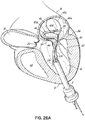
- FIGS. 1A-1F a device, system and method for positioning a helical anchor in the mitral position of a patient's heart are shown.
- the system is delivered from the apex of the left ventricle.
- the system can also be used by direct implantation into an open heart from the atrium, ventricle or aorta, or implantation can be made from catheters delivered into the left atrium or retrograde from the aortic valve into the left ventricle.
- the system could be introduced in an open chest into the atrium or percutaneously via the apex of the heart.
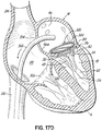
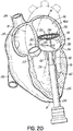
- FIG. 1A shows an introducer 2 inserted into the apex 6 of the left ventricle 10 of a patient's heart 14 by a small thoracotomy, a sternotomy, or from below the diaphragm with an upper abdominal incision.
- One particularly favorable approach is to make a small incision on the patient's chest near the apex 6 of the left ventricle 10 and then through the apex 6 of the heart 14.
- a standard purse string suture could be used to hold the introducer 2 in place and close the defect on removal. It is also possible to use an occluder device for entry and exit.
- a guidewire 30 is advanced from a lumen 34 of the introducer 2 through the left ventricle 10 and between the anterior and posterior leaflets 38, 42 of the native mitral valve 44 such that a portion of the guidewire 30 is positioned in the left atrium 46. Care should be taken when advancing the guidewire 30 to avoid entanglement of the guidewire 30 with the chordae tendineae 48 or their associated papillary muscles 56, 60.
- a delivery catheter 64 ( FIG. 1B ) may then be advanced upon the guidewire 30.
- the lumen 34 of the introducer 2 should be sufficiently large to allow entry of the various delivery system components.
- the introducer 2 may incorporate a check valve (not shown) to prevent blood leakage.
- a check valve (not shown) to prevent blood leakage.
- a large number of such devices have been described which often employ one or more duck-bill shaped valves.
- the guidewire 30 can be straight or feature a U-shaped tip or any convenient shape to allow entry into the left atrium 46.
- a delivery catheter 64 is introduced over the guidewire 30 into the left atrium 46.
- the delivery catheter 64 allows the introduction of a coil guide catheter 68.
- the coil guide catheter 68 has a preformed shape designed to assist in the introduction of a helical anchor 72, and can be composed of any material and/ or designed in any manner that allows it to be activated during use to the preformed shape. It may, for example, be designed such that it can be straightened and retain its preformed shape upon release.
- the coil guide catheter 68 can be formed from a shape memory material such as Nitinol (NiTi) or from a plastic that retains its shape.
- the coil guide catheter 68 could be a composite of several layers.
- the coil guide catheter 68 may comprise a Nitinol tube with a polymeric cover. It could also be composed of a mesh or weave of Nitinol with or without a cover. The interior could also be lined with a friction reducing material, such as a lubricious coating material to make it more smooth and slippery to introduce the helical anchor 72.
- the coil guide catheter 68 is straightened for introduction by the delivery catheter 64, which is relatively stiff compared to the coil guide catheter 68.
- Other options for obtaining the preformed shape may include introducing the distal end of the coil guide catheter 68 as a relatively straight element and then activating it such that it takes on the desired preformed shape, such as with one or more curves that will be discussed below and assist with proper introduction and positioning of the helical anchor 72.
- the coil guide catheter 68 may be directed to the mitral valve position without the use of a delivery device, such as the delivery catheter 64.
- a delivery device such as the delivery catheter 64.
- any of the various known manners of deflecting the distal end may be utilized.
- the coil guide catheter 68 is positioned in the left atrium 46 or just inside the left ventricle 10 near a mitral valve commissure 80. It should be noted that commissures 80 are the points where the anterior mitral leaflet 38 and posterior mitral leaflet 42 contact each other to close the mitral valve 44 at the valve perimeter or annulus 84. This position can be confirmed visually if the heart 14 is open. However, it is preferred to conduct this procedure with a closed and beating heart 14. In this case imaging modalities such as fluoroscopy, X-ray, CT or MR imaging can be used. Echocardiography in 2D or 3D can also be used to help guide the position. It should be appreciated that the coil guide catheter 68 can also be positioned in the left ventricle 10 for placement of the helical anchor 72.
- the coil guide catheter 68 assumes its preformed shape to facilitate the introduction of the helical anchor 72, as shown in FIG. 1C .
- the coil guide catheter 68 comprises a stem 88 and a U-shaped portion 92.
- the coil guide catheter 68 has a lumen 96 which is roughly circular with a diameter similar to the helical anchor 72 which it delivers.
- the U-shaped portion 92 of the coil guide catheter 68 is oriented generally parallel to the plane of the mitral valve 44 and helps to correctly position the depth of the coil guide catheter 68 inside the heart 14 so that the helical anchor 72 is extruded into the plane of the mitral valve 44. This ensures that the helical anchor 72 will be directed closely under the leaflets 38, 42.
- the tip 100 of the helical anchor 72 may also have a slight outward and downward turn to allow direction of the helical anchor 72 under the valve leaflets 38, 42.
- the coil guide catheter 68 is shown with a slight upward turn at the stem 88 before the U-shaped portion 92 that sits parallel to the valve 46. This is not necessary but helps to make pushing the helical anchor 72 into position less difficult.
- the distal portion of the coil guide catheter 68 need not be parallel to the valve 44 and annulus 84, as shown. It may instead be angled and yet the distal end of the helical anchor 72 will naturally orient itself downwardly and between the leaflets 38, 42 and then extrude and coil or spiral into the proper position. It should also be noted that no puncturing of valve, leaflet or heart tissue needs to take place.
- the helical anchor 72 has been advanced so that the end of the helical anchor 72 is starting to track under the posterior leaflet 42.
- the tip 100 of the coil guide catheter 68 is located above the plane of the valve 46, but it can also be located under the posterior leaflet 42. It should be noted that there is no need for penetration through any area of tissue.
- the helical anchor 72 is passed between leaflets 38, 42 near a commissure 80. It is appreciated that penetration through the leaflets 38, 42 could be used, but is less desirable due to the delicate nature of the leaflets 38, 42. It is also possible to pass the helical anchor 72 at any location, including a location that is distal from a commissure 80. This may result in folding or bending of one or both of the leaflets 38, 42 if the starting point is not at or near the commissure 80 once the helical anchor 72 is placed.
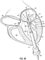
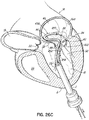
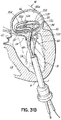
- FIG. 1D shows most of a complete revolution of the helical anchor 72 positioned under the mitral valve 44.
- the number of lower coils 104 of the helical anchor 72 can vary from less than one to as many as the operator thinks is useful.
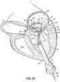
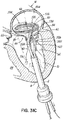
- upper coils 108 of the helical anchor 72 are positioned above the annulus 84 by rotating the coil guide catheter 68 as the helical anchor 72 is advanced. This is shown in FIG. 1E .
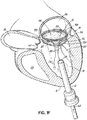
- FIG. 1F shows that about two coils 108 have been placed above the mitral valve annulus 84 and about two coils 104 have been placed below the mitral valve annulus 84.
- the arrangement shown can be varied. There may be any number of coils 104, 108 as the operator sees fit. It should be noted that even a portion of a coil 104,108 above or below the annulus 84 may be sufficient to retain the helical anchor 72.
- the size of the helical anchor 72 can be preselected before placement so that it closely matches the diameter of the annulus 84. This maximizes the size of the replacement valve implant that can be placed inside the helical anchor 72 and helps reduce the risk of a leak at the commissures 80.
- the gap between the coils 104, 108 can be adjusted when making the helical anchor 72. By leaving a slightly larger gap between the coils 104, 108 sitting above and below the annulus, it is possible to allow the valve tissue 44 to close at the commissures 80 by permitting a small amount of motion of the leaflets 38, 42 as the heart 14 contracts. This is one strategy to ensure there is no leak around the helical anchor 72.
- the coils 104, 108 do not need to trap the leaflet tissue 38, 42.
- leaving a gap between the ventricular and atrial coils 104, 108 may be advantageous in permitting the leaflet tissue 38, 42 to close at the commissures 80 and prevent blood flow leakage at these locations.
- the atrial coil or coils 108 may be of larger diameter or even shaped differently than a "coil" such that it comprises an extension that engages a portion of the atrial wall 46a above the annulus 84.
- a sufficient gap between at least the coils 104, 108 i.e., a gap that spans the annulus 84 when the anchor 72 is implanted
- the atrial coil or coils 108 may be of larger diameter or even shaped differently than a "coil” such that it comprises an extension that engages a portion of the atrial wall 46a above the annulus 84.
- Various other designs for atrial and/or ventricular anchor stabilization are possible as well.
- FIG. 1F shows the coils 104 wrapping around the anterior leaflet 38 of the mitral valve 46 which is near the aortic valve 22.
- the anterior leaflet 38 is engaged by the lower coils 104 of the helical anchor 72 and is thereby restricted from obstructing the flow of blood into the aortic valve 22.
- the coils 104 can also be adjusted to sit even lower than shown if additional control of the anterior mitral leaflet 38 is desired.
- the number of lower coils 104 in the helical anchor 72 can be adjusted to cover more of the anterior mitral leaflet 38.
- the lower coils 104 can sit high against the annulus 84, or lower in the ventricle 10.
- the patient's native mitral valve 44 continues to work, i.e., the leaflets 38, 42 continue to open and close during the heart cycle as required.
- the valve 44 can open and close normally despite some restriction of the opening by the coils 104, so that functionally the patient can remain stable. This allows an operator to implant a valve prosthesis within the anchor 72 without the risk of the patient being in a position of hemodynamic compromise. Therefore, the procedure can be performed on a beating heart 14 without a heart-lung machine.
- Another feature of this design is that when the replacement valve (i.e., prosthesis) is positioned, the location of the replacement valve (e.g.
- valve prosthesis or replacement valve implant in the annulus, relatively higher than the annulus, or in the ventricle can be chosen by the location of the coils 104, 108 and by the physician's decision about the optimal placement of the valve prosthesis. This allows a valve prosthesis or replacement valve implant to sit lower or higher in the annulus 84 depending on the particular design of the helical anchor 72 and the patient's anatomy and clinical situation.
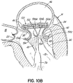
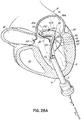
- FIG. 1G shows a helical anchor 72 that has been implanted with approximately three coils 108 above the mitral valve annulus 84 in the left atrium 46 and approximately two coils 104 below the annulus 84 in the left ventricle 10.
- the anterior and posterior leaflets 38, 42 are engaged by the coils 104, 108 of the helical anchor 72.
- the anterior leaflet 38 is restrained by the coils 104, 108 so that it is prevented from obstructing the flow of blood into the aortic valve 22.
- At least one or more of the coils 104 below the annulus have diameters greater than the diameter of at least one or more of the coils 108 above the annulus 84. This type of design can have a number of benefits.
- the use of smaller diameter coils 108 at the location where a mitral valve prosthesis 120 will be implanted allows for implantation of a smaller sized prosthesis 120, and this can be advantageous for various reasons.
- Some patients may have a large diameter annulus 84 and a doctor may want to implant a smaller prosthesis 120. This will also help prevent obstruction of the aortic valve 22.
- the valve prosthesis retention coils 108 e.g.
- the smaller coils may also extend higher into the left atrium 46 such that the prosthesis is also positioned higher and away from the aortic valve 22.
- the coils 104, 108 of the helical anchor are not required to have the same diameter. Rather, it may be appropriate for the diameter to vary on each turn or coil 104, 108.
- the coils 104, 108 are not required to be precisely circular. It may be useful to have turns in the coils that are more oval or elliptical in shape. For example, an elliptical shape may be useful if the coils 108 above the annulus 84 seat against the atrial wall 46a rather than on the native mitral valve 44 itself.
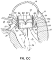
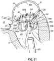
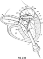
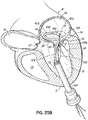
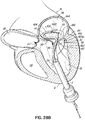
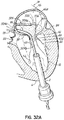
- a valve prosthesis 120 is retained by a helical anchor 72 in the mitral position.
- the valve prosthesis 120 comprises a pair of artificial leaflets 122, 124 mounted within an expanded stent structure 126.
- the artificial leaflets 122, 124 may comprise pliable animal tissue such as cow, pig or horse pericardium or animal valve tissue.
- Many variations of percutaneous valves 120 have been described for implantation with a catheter, such as those used for aortic valve replacement.
- the valve prosthesis 120 can be self expanding, such as previously described percutaneous valves based on a shape memory stent such as Nitinol (NiTi), or balloon expandable such as a stainless steel or non-shape memory stent material.
- the valve prosthesis 120 can be introduced through the same introducer 2 initially shown in the apex 6 of the left ventricle 10. This portion of the procedure is well known since thousands of percutaneous valve implants are performed each year, and all appropriate technologies and methods can be employed to insert the valve prosthesis 120 and anchor it into the helical anchor 72 as shown.
- the helical anchor 72 can be seen on X-ray, MR, CT and echocardiography to help position the valve prosthesis 120 and perform the procedure. Radiopaque markers such as gold may be added to the surface of the shape memory materials to improve X-ray identification.
- the valve prosthesis 120 is docked to the helical anchor 72 such that the anterior and posterior leaflet tissue 38, 42 is secured between the anchor 72 and the valve prosthesis 120. This serves to lock the anchor 72 in position and prevent it from moving or dislodging.
- the leaflet tissue 38, 42 also creates a natural seal to prevent blood flow between the valve prosthesis 120 and helical anchor 72.
- locking of the anchor 72 can also be completed by placing coils 108 of the anchor 72 above the mitral valve 44 such that the upper coils 108 do not compress the valve leaflets 38, 42 but instead abut the atrial wall 46a.
- the replacement valve 120 can be anchored against the coil(s) 108 of the anchor 72 above the annulus 84, below the annulus 84 or both.
- FIG. 1H shows a valve 120 that is relatively centered and is anchored against the coils 104, 108 about equal amounts above and below the annulus 84. The precise position can be chosen by the operator. Also, the coils 104, 108 can be adjusted (more coils 104, 108 on the atrial or ventricular side) to help facilitate locating the valve 120.
- valve prosthesis 120 may not be attached to the helical anchor 72 both above and below the annulus 84.
- the coils 108 above the annulus 84 do not necessarily need to abut the valve prosthesis 120.
- anchoring of the valve prosthesis 120 can be achieved by only engaging the anterior and posterior leaflets 38, 42 against the coils 104 below the annulus 84. There can be minimal or no coils 108 of the helical anchor 72 above the annulus.
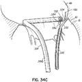
- the entire procedure can be performed through the atrium 46 or via a transseptal puncture. More details of a transseptal procedure will be shown and described below.
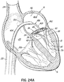
- FIG. 1I shows a helical anchor 72.
- the anterior and posterior leaflets 38, 42 are engaged by the coils 104 of the helical anchor 72 below the mitral valve annulus 84 in the left ventricle 10.
- the anterior leaflet 38 is restrained by the coils 104 so that it is prevented from obstructing the flow of blood into the aortic valve 22.
- the coils 108 on the opposite side of the valve 44 in the left atrium 46 do not contact the leaflets 38, 42 but anchor against the atrial wall 46a.
- This arrangement keeps the anchor 72 from moving as in previous descriptions but relies on the atrial wall 46a rather than valve leaflets 38, 42 to support the upper coils 108.
- the helical anchor 72 cannot move upward toward the atrium 46 due to the contact with the leaflets 38, 42 below the valve 44, and it cannot move downward due to the contact with the atrial wall 46a.
- helical anchors 72 could be constructed such that coils 104, 108 sit below the valve 44 and above the valve 44, but there is a gap between the coils 104 below the valve 44 and coils 108 above the valve 44. Valve leaflets 38, 42 would not be trapped between coils 104, 108 of the helical anchor 72. This arrangement allows the mitral valve 44 to approximate naturally at the commissures 80 because the leaflet tissue 38, 42 is not trapped between coils 104, 108 and can prevent leaks at the commissures 80.
- Additional coils 104, 108 may be added which would extend from the top of the coils 108 previously described in the left atrium 46 to anchor against the atrial wall 46a. This arrangement may allow a valve prosthesis 120 to be fastened to coils 104, 108 above and below the annulus 84 to improve the stability of the valve prosthesis 120 and anchor to the atrial wall 46a. It should be noted that in addition to the gap between coils 104 and 108, both the diameter of the helical anchor 72 and shape of the coils 104, 108 could be varied. The helical anchor 72 does not need to be uniform in diameter or profile.
- the coils 108 above the annulus 84 might be made thicker than the coils 104 below the annulus 84 for more strength of attachment to the atrial wall 46a. There could be thicker and thinner areas of the coils 104, 108 as needed for strength or function. Furthermore, the cross sectional shape of the coils 104, 108 does not need to be circular.
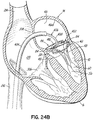
- FIG. 1J shows a valve prosthesis 120 that has been anchored to the helical anchor 72 shown in FIG. 1I .
- the valve prosthesis 120 comprises a pair of artificial leaflets 122, 124 mounted within an expandable stent structure 126.
- the artificial leaflets 122, 124 may comprise pliable animal tissue such as cow, pig or horse pericardium or animal valve tissue.
- pliable animal tissue such as cow, pig or horse pericardium or animal valve tissue.
- Various suitable valve prostheses have been previously described.
- the valve prosthesis 120 is docked to the helical anchor 72 such that the anterior and posterior leaflet tissue 38, 42 is secured between the anchor 72 and the valve prosthesis 120. This serves to lock the anchor 72 in position and prevent it from moving or dislodging.
- the leaflet tissue 38, 42 also creates a natural seal to prevent blood flow between the valve prosthesis 120 and helical anchor 72.
- more coils 108 could be placed above the annulus 84 (in addition to the coils 108 which contact the atrial wall 46a) so that the valve prosthesis 120 could anchor to coils 104, 108 of the helical anchor 72 above and below the annulus 84 as previously described with reference to FIG. 1H .
- the coils 108 above the annulus 84 could easily not abut the leaflets 38, 42, but rather there could be a gap between the coils 108 above and coils 104 below the annulus 84 such that there is no trapping of leaflet tissue 38, 42 between coils 104, 108.
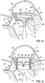
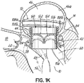
- FIG. 1K shows a helical anchor 72 having a varied coil configuration.
- the anchor 72 is held in place by coils 108a extending above the annulus 84 which abut against the atrial wall 46a and by coils 104 extending below the annulus 84 which abut against the ventricular wall 10a. Additional coils 108b above the annulus 84 engage and hold a valve prosthesis 120 without contacting either of the anterior or posterior leaflets 38, 42.
- the valve prosthesis 120 comprises a pair of artificial leaflets 122, 124 mounted within an expandable stent structure 126.
- the artificial leaflets 122, 124 may comprise pliable animal tissue such as cow, pig or horse pericardium or animal valve tissue.
- Various suitable valve prostheses have been previously described.
- the coils 104 of the helical anchor 72 below the annulus 84 may not trap the anterior and posterior leaflet tissue 38, 42 between the anchor 72 and the valve prosthesis 120 sufficiently to create a seal between the helical anchor 72 and valve prosthesis 120 or prevent the anterior leaflet 38 from obstructing blood flow into the aortic valve 22. Therefore, the coils 104 below the leaflets 38, 42 may be adjusted to tightly secure the leaflets 38, 42 against the valve prostheses 120, rather than abutting the ventricular wall 10a. Securing the anterior leaflet 38, such as in any of the manners described herein can be important for purposes of preventing obstruction of blood flow from the left ventricle 10 through the aortic valve 22.
- coils 108a and 108b may be configured such that the prosthesis 120 can be implanted at a desired height relative to the annulus 84. In addition to preventing obstruction of the aortic valve 22 with the prosthesis 120, this can prevent the prosthesis from contacting the walls of the left ventricle 10, which could lead to rupture of the left ventricle 10. This latter case can be especially important for patients with small left ventricles.
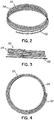
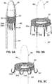
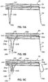
- FIGS. 2, 3 and 4 show a helical anchor 130 wherein the lower coils 132, or first approximately two coils, of the anchor 130 have diameters that are greater than the diameter of the remaining upper coils 134. This allows for easy engagement with the mitral annulus 84 ( FIG. 1A ) during insertion.
- the lower coils 132 of the anchor 130 extend slightly downward creating gaps so that the lower coils 132 do not press against each other, while the upper coils 134 are shown contacting each other. This feature allows the initial lower coil 132 to slip to the opposite side of the mitral leaflets 38, 42 as it is inserted and to avoid unwanted friction or drag as the anchor 130 is pushed into place.
- anchors may have coils of varying diameters, coils spaced with varying gap sizes, and coils which taper, expand, or flare larger or smaller. It should be noted that the coils may stretch radially outward when the valve prosthesis 120 ( FIG. 1H ) is placed or expanded within the helical anchor 72 or 130. This is seen particularly in the middle coils. Therefore, even though the coils may have different diameters initially, the coils may all contact the valve prosthesis 120. It should also be noted that a valve prosthesis 120 may have a varying diameter, which may be designed for optimal contact with a desired number of coils of the helical anchor 72 or 130 to improve retention.
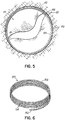
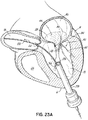
- FIG. 5 illustrates a helical anchor 140 for docking a valve prosthesis (not shown) which passes through one of the two commissures 80 of the mitral valve 44.
- Coils 142, 144 of the anchor 140 are located above and below the annulus 84, and a connecting segment 146 is located across the commissure 80 without passing through valve tissue.
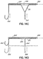
- FIG. 6 illustrates another helical anchor 150, wherein the anchor 150 is shaped as a simple helix with no taper and a slight outward turn 152 at one end to facilitate initial turning of the helical anchor 150 under the annulus 84 ( FIG. 1A ).
- gaps 154 are provided between the coils 156 of the anchor 150 to prevent unwanted friction or drag as the anchor 150 is pushed into place.
- the slight outward turn, or outward extension has a larger radius from the center of the anchor 150 than the next adjacent coil.
- the distal end or outward turn 152 may also be oriented downward or away from the next adjacent coil in a direction generally along the central axis of the helical anchor 150, as shown.
- the distal end 152 extends radially outward and downward relative to the next adjacent coil 154 to create a gap or spacing between end 152 and coil 154 that exists prior to implantation.
- This design feature also helps avoid tangling or interference with the chordae tendineae 48 and/or leaflets 38, 42 during insertion of the helical anchor 150 and with downsizing needs when a smaller prosthesis 120 is to be implanted.
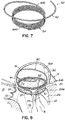
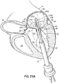
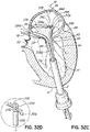
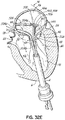
- a helical anchor 160 may include a tail-like extension 162 as shown in FIG. 7 .
- the uppermost helical convolution 162 is of larger diameter than lower coils 164 so as to make contact with or abut the atrial wall 46a as shown in FIG. 8 .
- the coils 164a of the helical anchor 160 below the mitral valve annulus 84 in the left ventricle 10 engage the anterior and posterior leaflets 38, 42.
- the anterior leaflet 38 is restrained by coils 164a so that it is prevented from obstructing the flow of blood into the aortic valve 22.
- the tail-like extension 162 assists in preventing the helical anchor 160 from moving.
- the tail-like extension 162 may not comprise a helical shape.
- the tail-like extension 162 can comprise a simple straight segment passing outward from the helical anchor 160 at an angle of approximately 90 degrees.
- a wide variety of tail-like extensions or other atrial anchoring features could be used.
- the tail-like extension 162 could eliminate entirely the need for coils 164b above the valve leaflets 38, 42 to engage the leaflets 38, 42.
- the coils 164b above the leaflets 38, 42 could be eliminated or the coils 164b above the leaflets 38, 42 could be arranged to produce a gap above the leaflets 38, 42.
- the gap can allow the helical anchor 160 to have a much longer contact with the valve prosthesis 120 ( FIG. 1H ). This can help to orient the valve prosthesis 120 so that it is aimed appropriately into the left ventricle 10 and atrium 46. It is important to ensure that the inflow of the valve prosthesis 120 into the ventricle does not abut against the posterior wall 10a of the left ventricle 10, as this may cause wear and rupture of the heart 14, or an impairment of flow into the left ventricle 10.
- a helical anchor incorporates a gap between the upper and lower coils of a helical anchor, as described previously herein, there may be a weak point in the system that is prone to fracture.
- the segment of the helical anchor that connects the coil above the valve 44 to that below the valve 44 may move rhythmically with the heart's contraction and fracture.
- anchoring the valve prosthesis 120 to coils both above and below the leaflets 38, 42 will lock these two helical coil portions together, preventing relative motion.
- connecting segment between upper and lower helices would not be needed after replacement valve implantation. Connection of upper and lower coil portions is necessary only for the insertion of the helical anchor.
- the connecting segment between upper and lower coil portions could be purposely made expendable (small and thin) or removable.
- a delivery apparatus 180 comprises an external sheath 182 and an internal shaft 184 having a converging tip 186.
- a helical anchor 190 is placed over the shaft 184 and restrained within the sheath 182, shown in dash-dot lines, in order to tighten the coils 192 of the anchor 190 prior to implanting.
- the converging tip 186 is provided to assist an operator with guiding the apparatus 180 through a patient's venous system, if used percutaneously, or through the patient's heart.
- Anchoring arms 194 such as hooks are provided along a coil 192a of the helical anchor 190, and are constructed of a shape memory material.
- the anchoring arms 194 have two spaced apart wire portions 194a, 194b to provide a strong anchor point to hold tissue.
- the anchoring arms 194 are restrained and straightened in a downward orientation within the external sheath 182.
- the coils 192 of the anchor 190 are released and spring radially outward to their natural diameter and the anchoring arms 194 fold in an upward direction forming hooks to engage tissue, as shown in FIGS. 9B and 9C .
- a delivery catheter 200 is inserted into the left ventricle 10 of a patient's heart 14.
- the delivery catheter 200 includes a lumen 202 which carries a delivery apparatus 180 as previously described, for example, having an external sheath 182 and a shaft 184 with a converging tip 186.
- a helical anchor 190 having anchoring arms 194 is compressed over the shaft 184 and retained by the sheath 182 such that the coils 192 of the anchor 190 are tightened.
- the tip 186 assists the advancement of the delivery apparatus 180 between the anterior and posterior leaflets 38, 42 of the mitral valve 44 from the left ventricle 10 into the left atrium 46 as shown in FIG. 10A .
- FIG. 20 shows the right atrium 210, inferior vena cava 212, superior vena cava 214, aortic valve 22, and aorta 18 (in dash-dot lines).
- the anchoring arms 194 unfold and expand, for example, into hooks.
- the hooks 194 wrap around the anterior and posterior leaflets 38, 42 and hold the anchor 190 in position, as shown in FIGS. 10B and 21 .
- the anchoring arms, or hooks in this case also capture or otherwise secure the leaflets 38, 42 and help prevent the anterior leaflet 38 from obstructing blood flow out of the left ventricle 10 through the aortic valve 22.
- the edges of the valve leaflets 38, 42 are attached to chordae tendineae 48 which extend from papillary muscles 56, 60.
- the hooks 194 are constructed in a shape that is relatively narrow at the distal ends 194c in order to pass between the chordae tendineae 48 (see FIGS. 9B and 9C ).
- FIG. 21 shows alternative hooks 194 that are wide at the distal ends 194c to form loops.
- the wide-loop hooks 194 of FIG. 21 provide improved retention of the valve leaflets but may be difficult to position around the chordae tendineae 48.
- a valve prosthesis 120 is positioned and retained within the helical anchor 190 as shown in FIGS. 10C and 22 .
- the valve prosthesis 120 is mounted in a stent 126 and comprises a pair of artificial leaflets 122, 124.
- the artificial leaflets 122, 124 may comprise pliable animal tissue such as cow, pig or horse pericardium or animal valve tissue.
- the valve prosthesis 120 may be self expanding or balloon expandable.
- Leaflet tissue 38, 42 is retained by hooks 194 toward the valve prosthesis 120, preventing the anterior leaflet 38 from obstructing blood flow through the aortic valve 22.
- a circumferential cuff 220 is inserted between the helical anchor 190 and the valve prosthesis 120 in order to improve retention of the valve prosthesis 120 in the atrium 46 and to provide a seal between the anchor 190 and the valve prosthesis 120 to prevent leakage.
- FIGS. 11A-11C illustrate the transition of an anchoring arm 194 from a straightened position ( FIG. 11A ) to an activated position ( FIG. 11C ).
- the anchoring arm 194 may be constructed of shape memory materials.
- FIG. 11A shows anchoring arms 194 each having a fixed end 222 and a free end 224 located along a coil 192a.
- the free end 224 may move away from the fixed end 222, causing the base of the anchoring arm 194 to elongate, and the distal tip 194c of the anchoring arm 194 may begin to bend or fold upward as shown in FIG. 11B .
- the anchoring arm 194 is activated when the distal tip 194c is bent to its original shape forming a hook as shown in FIG. 11C .
- the anchoring arm 194 may have no fixed end 222, but rather two free ends 224 so that it may slide along the helical anchor 194 at both ends.
- the number and configuration of anchoring arms 194 provided may vary.
- FIG. 12A shows a stent dock 230 with anchoring arms such as hooks 232 at the bottom.
- the hooks 232 may be separately attached or integrated into the construction of the stent dock 230.
- the midpoint of the stent dock 230 is shown as dash-dot line or axis 234.
- the hooks 232 are attached to the apex 236 of each lowermost cell 238 of the stent dock 230.
- Other stent docks may incorporate double sided hooks (such as shown in FIGS. 11A-11C ) that are anchored with one base on one cell 238 and one base on another cell 238.
- the cells 238 collapse vertically causing the hooks 232 to rise such as to engage leaflet tissue. In this manner shortening of the stent dock 230 (i.e., radial expansion thereof) is used in a functional way to activate the hooks 232.
- FIG. 12B shows another stent dock 240 as it expands so that the stent dock 240 shortens and anchoring arms such as double-hooks 242 are lifted in a manner similar to that described with reference to FIG. 12A .
- Additional stent docks may include a wide variety of hook types and attachment structure.
- double-wire hooks may be attached with one wire end at the bottom of a first cell 244 of the stent dock 240, and another wire end at the bottom of an adjacent cell 244 of the stent dock 240. This arrangement would cause the base of the hook 242 to lengthen as the stent dock 240 is expanded. In this manner a hook 242 could start to engage tissue with a narrow shape and then widen as the stent dock 240 is expanded. This may be a useful feature when a hook 242 is attached to a valve leaflet between chordae tendineae.
- hooks 250 are shown spread along a serpentine wire 252.
- the turns 254 of the wire 252 separate the hooks 250.
- the hooks 250 spread apart and become elevated as shown in FIG. 13B . In this manner the hooks 250 may be activated to retain tissue.
- FIGS. 14A and 14B illustrate hooks 250 spread along a serpentine wire 252 which is mounted on a central retaining wire 256.
- the hooks 250 spread apart and become elevated as the serpentine wire 252 is straightened along the central retaining wire 256 as shown in FIG. 14B .
- the central retaining wire 256 may, for example, comprise a helical anchor (such as described herein) which carries a serpentine wire 252 thereon.
- FIGS. 14C and 14D illustrate yet another method of hook deployment.
- a wire 260 is folded such that a plurality of anchoring arms such as hooks 262 having V-shaped portions are provided.
- the wire 260 is placed within an outer shell or hollow structure 264 having apertures 266 such that the hooks 262 are permitted to extend through the apertures 266 as shown in FIG. 14C .
- V-shaped portions 270 retract and straighten within the shell 264 causing the hooks 262 to lift upward as shown in FIG. 14D .
- FIGS. 15A-15F a system and method for positioning a stent dock 280 in the mitral position or location of a patient's heart 14 is shown.
- FIG. 15A shows an introducer 2 inserted into the apex 6 of the left ventricle 10 by a small thoracotomy, a sternotomy, or from below the diaphragm with an upper abdominal incision.
- One particularly favorable approach is to make a small incision on the patient's chest near the apex 6 of the left ventricle 10 and then through the apex 6 of the heart 14.
- a standard purse string suture could be used to hold an introducer 2 in place and close the defect on removal.
- a guidewire 30 is advanced such that a portion of the guidewire 30 is positioned in the left atrium 46. Care should be taken when advancing the guidewire 30 to avoid entanglement of the guidewire 30 with the chordae tendineae 48 or their associated papillary muscles 56, 60.
- a delivery catheter 64 may then be advanced upon the guidewire 30.
- the delivery catheter 64 contains the stent dock 280 and is directed into the left atrium 46.
- An atrial portion 280a of the stent dock 280 is extruded (i.e., extended) by withdrawing the delivery catheter 64 as the stent dock 280 is held in place as shown in FIGS. 15B and 15C . This could also be accomplished by pushing the stent dock 280 outward from the delivery catheter 64.
- the stent dock 280 can be constructed in a variety of ways, it is useful to construct the stent dock 280 from a shape memory material such as Nitinol. It should be noted that the stent dock 280 may be cut from a tube or piece of material, or may be woven from threads or pieces of shape memory material.
- the stent dock 280 has an option of allowing blood to flow around it and through it. This is facilitated by the stent matrix as shown in FIG. 15B .
- Portions of the stent dock 280 may be coated with one or more of fabric, polymers, and biologic material. It is noted that a fabric coating may be particularly useful to prevent leaks and encourage tissue ingrowth around the annulus 84 of the mitral valve 44. Suitable fabrics may include Dacron and Teflon materials.
- the stent dock 280 and delivery catheter 64 are lowered together as shown in FIGS. 15C and 15D so that the atrial portion 280a of the stent dock 280 may contact the atrial wall 46a and the valve anchoring portion 280b of the stent dock 280 is positioned within the mitral valve 44 as shown in FIG. 15D .
- the valve anchoring portion 280b may also be coated with material such as Dacron or Teflon to promote tissue ingrowth and help prevent leaks. As illustrated in FIG.
- the delivery catheter 64 is retracted further and releases anchoring arms in the form of ventricular hooks 284 of the stent dock 280, allowing the hooks 284 to travel between the chordae tendineae 48 and wrap around the mitral valve leaflets 38, 42.
- the atrial portion 280a retains the stent dock 280 in the left atrium 46 and the stent dock 280 is held stable inside the heart 14.
- the valve anchoring portion 280b is in a closed position, but may expand in the direction of the arrows upon insertion of a valve prosthesis 120 ( FIG. 15G ). It should be noted that the native mitral valve 44 may still open and close so that the heart 14 still functions and the patient remains stable during the procedure. Therefore, there is no critical time constraint placed on the operator while preparing to implant the valve prosthesis 120.
- a delivery catheter device or devices may be constructed so that the stent dock 280 can be released from two ends.
- a catheter could retain the atrial portion 280a with or without the valve anchoring portion 280b of the device and a separate catheter could retain the ventricular hooks 284.
- the more proximal catheter could be withdrawn to allow the hooks 284 to open first.
- This step could be performed with the hooks 284 low in the ventricle 10 and the entire stent dock 280 could be pushed forward toward the valve 44, ensuring that the valve leaflets 38, 42 are retained by the hooks 284.
- the stent dock 280 can be pulled back and repositioned.
- the hooks 284 have properly engaged the valve leaflets 38, 42, the more distal catheter could be withdrawn to allow the atrial portion 280a to expand.
- Additional maneuvers may assist positioning of the stent dock 280.
- restricting leaflet motion may help to allow the hooks 284 to secure all leaflet components. This could be performed pharmacologically by reducing flow through the mitral valve via negative inotropes or vasodilators to pool blood in the periphery of the patient or by table positioning. Mechanical devices such as occluders or balloons could be inflated near the mitral valve to limit flow.
- the atrial portion 280a of the stent dock 280 could be adapted to impair flow, or a flow impairing stent structure could be incorporated thereon. Still alternatively, the atrial portion 280a could have fabric attached in part or covering its entire surface to restrict flow. This fabric could also be used to promote tissue ingrowth and long term biocompatibility.
- the stent dock 280 has been positioned.
- the valve retaining portion 280b of the dock 280 has expanded or dilated, causing the hooks 284 to lift or move upward toward the atrial portion 280a of the dock 280.
- the hooks 284 pull upward on the mitral valve tissue so that the valve 44 may no longer open and close.
- the mitral valve leaflet tissue 38, 42 is compressed by the hooks 284 to form an excellent gasket or seal around the stent dock 280.
- the mitral leaflet tissue 38, 42 forms a ring of compressed native biologic material that strengthens the dock 280 and prevents any leaks around the stent dock 280.
- the expansion of the valve retaining portion 280b causes the atrial portion 280a and hooks 284 to hold the dock 280 in place.
- the expansion of the valve retaining portion 280b can be effected by a variety of means.
- a draw string (not shown) could be used to pull the hooks 284 toward the atrial portion.
- a series of draw strings (not shown) could be used to pull hooks 284 and segments of the atrial portion 280a together.
- both the atrial portion 280a and the ventricular hooks 284 of this device 280 could have many variations.
- the atrial portion 280a may not be composed of complete cells.
- the atrial portion 280a may comprise radial arms (not shown) extending outward and not a complete circle of stent material.
- the atrial portion 280a could comprise a spiral of material similar to the tail-like extension 162 shown previously to anchor the helical anchor in the atrium in FIG. 8 .
- valve prosthesis 120 is implanted within the valve retaining portion 280b as shown in FIG. 15G .
- the valve prosthesis 120 may be as previously described, for example.
- the expansion of the valve prosthesis 120 may cause the retaining portion 280b to expand, which allows the hooks 284 and atrial portion 280a to firmly retain the stent dock 280.
- the valve prosthesis 120 may be integrated within the stent dock 280 prior to implantation to avoid the secondary step.
- FIGS. 16A-16C show the stent dock deployment without a delivery catheter to provide closer detail.
- the atrial portion 280a is shown opening in FIGS. 16A and 16B .
- the spaces between the struts 290 of the atrial portion allow for minimal or no interruption of blood flow.
- FIG. 16C shows the atrial portion 280a resting in the plane 292 of the mitral valve, shown in dash-dot lines.
- the valve retaining portion 280a is beginning to expand, causing the hooks 284 to elevate.
- FIG. 16D illustrates the valve retaining portion 280b is fully expanded, resulting in the hooks 284 being lifted to their deployed position.
- a catheter 302 is introduced into a patient's venous system by percutaneous puncture or by a small surgical cut down at the patient's groin, as is commonly known.
- the catheter 302 may be introduced anywhere in the lower abdomen or retroperitoneal region, or in the neck or shoulder regions via the subclavian or axillary veins or the jugular system in the neck.
- the catheter 302 is advanced up the inferior vena cava 212, into the right atrium 210, across the atrial septum 304, and into the left atrium 46 as shown in FIG. 17A .
- the tricuspid valve 306, right ventricle 210, superior vena cava 214, and aorta 18 of the patient's heart 14 are show for illustrative purposes.
- a coil guide catheter 310 is carried by the catheter and extends between the anterior and posterior leaflets 38, 42 of the mitral valve 44 into the left ventricle.
- the system is preferably inserted via the venous system, which is low in pressure and can accommodate large catheters and guides. This allows flexibility in developing and introducing catheters, systems, devices and methods for remote mitral valve replacement.
- the system may be introduced directly into the left atrium 46 without a transvenous approach, or via the aorta 18.
- the catheter 302 can be passed from the aorta 18 to the left ventricle 10 and then into the left atrium 46.
- the aorta 18 can be accessed directly as in an open surgical procedure, or from any of its branches so that the system may be introduced in the groin, shoulder, retro peritoneum, chest, or abdomen of the patient.
- a coil guide catheter 310 is extended into the left ventricle 10 and assumes its original shape.
- the coil guide catheter 310 comprises a stem 312 and a U-shaped portion 314.
- the lower coils 316 ( FIG. 17C ) of a helical anchor 320 are extruded (i.e., extended) from the coil guide catheter 310 inside the ventricle 10.
- the lower coils 316 wrap around the chordae tendineae 48 and the mitral valve 44.
- the precise level at which the lower coils 316 are extruded can be determined by adjusting the level of the coil guide catheter 310 in the left ventricle 10.
- chordae tendineae 48 originates from two papillary muscle heads 56, 60 located substantially below the mitral valve 44. Due to the higher concentration of the chordae tendineae 48 near the papillary muscle heads 56, 60, it may be desirable to encircle the chordae tendineae 48 at a lower level.
- the coil guide catheter 310 is drawn up into the left atrium 46. See FIG. 17C .
- the act of withdrawing the coil guide catheter 310 into the atrium 46 can be used to pull the lower coils 316 of the helical anchor 320 placed in the ventricle 10 to a higher level in order to contact the mitral valve 44 as shown in FIG. 17C .
- the upper coils 322 of the helical anchor 320 are released in the atrium 46 by retracting the coil guide catheter 310 inside the catheter 302.
- the coil guide catheter 310 is retracted and the catheter 302 is withdrawn.
- Coils 316, 322 of the anchor 320 contact the mitral valve 44 both above and below the leaflets 38, 42.
- the upper coils 322 may not contact the mitral valve 44 but may be supported against the atrial wall 46a.
- a helical anchor having a gap between the lower and upper coils 316, 322 could be positioned so that the leaflets 38, 42 are not trapped between coils 316, 322 and to improve orientation of a subsequently placed valve prosthesis (not shown).
- FIG. 17D also illustrates that ventricular coils 316 contain leaflets 38, 42.
- coils 316 there may be gaps between coils 316 and/or gaps between coils 322, and that different numbers of coils than those shown in the drawings may be utilized.
- additional coils 316 are used in the ventricle 10, this can provide further prosthetic valve support and help further contain the anterior leaflet 38 from obstructing the aortic valve 22.
- Additional coils 322 in the atrium 46 can also provide further prosthetic valve stabilization and also allow the prosthetic valve to be positioned higher in the atrium 46 so that it does not obstruct the aortic valve 22.
- the lower and upper coils (i.e., ventricular and atrial coils) 316, 322 are joined by a segment of the anchor that is located at the leaflets 38, 42. This may impair leaflet closure and cause a leak in the valve 44. However, this situation will not persist for a long time since a percutaneous replacement valve 120 can be deployed immediately after placing the anchor 320. Also, the segment of the anchor 320 joining the atrial coils 322 and ventricular coils 316 may sit near a commissure 80 ( FIG. 15A ) and not interfere with valve closure.
- the wire of the anchor 320 could be preformed so that it would travel through the center of the native mitral valve 44 and allow the two mitral valve leaflets 38, 42 to approximate each other.
- a wide variety of helical anchor configurations, such as those previously described herein, may be incorporated.
- a catheter 332 is introduced into a patient's venous system by percutaneous puncture or by a small surgical cut down at the patient's groin, as is commonly known.
- the catheter 332 may be introduced anywhere in the lower abdomen or retroperitoneal region, or in the neck or shoulder regions via the subclavian or axillary veins or the jugular system in the neck.
- the catheter 332 is advanced up the inferior vena 212 cava, into the right atrium 210, across the atrial septum, and into the left atrium 46 as shown in FIG. 18A .
- a coil guide catheter 340 extends from the catheter 332 into the left atrium 46 with its distal tip 340a at or near the mitral valve 44.
- the helical anchor 330 is extruded from the tip 340a of the coil guide catheter 340 under the mitral valve 44 through a commissure 80 between the anterior and posterior leaflets 38, 42.
- the coil guide catheter 340 comprises a stem 342 and a U-shaped portion 344 to assist in the extrusion of the helical anchor 330.
- the system is preferably inserted via the venous system, which is low in pressure and can accommodate large catheters and guides. This allows flexibility in developing and introducing catheters, systems, devices and methods for remote mitral valve replacement.
- the system may be introduced directly into the left atrium 46 without a transvenous approach, or via the aorta 18.
- the catheter 332 can be passed from the aorta 18 to the left ventricle 10 and then into the left atrium 46.
- the aorta 18 can be accessed directly as in an open surgical procedure, or from any of its branches so that the system may be introduced in the groin, shoulder, retro peritoneum, chest, or abdomen of the patient.
- upper coils 348 may be positioned above the mitral valve 44 in the atrium 46.
- Approximately two lower coils 346 of the anchor 330 are positioned under the mitral valve 44. It is appreciated that any desired number of coils 346 may be positioned under the mitral valve 44.
- the upper coils 348 of the anchor 330 are released from the coil guide catheter 340 above the mitral valve 44 by rotating the coil guide catheter 340 as shown in FIG. 18B .
- the catheter 332 has a turn 332a at its distal end.
- the turn 332a may be deactivated so that the upper coils 348 are delivered above the valve 44 from a location closer to the atrial septum 304. This would allow the coils 348 to assume their preformed position with relative ease, and would eliminate the need to rotate the catheter 332.
- FIG. 18C illustrates the completed placement of the helical anchor 330 in the mitral position, such that approximately two lower coils 346 of the anchor 330 are positioned under the mitral valve 44 and approximately two upper coils 348 are positioned above the mitral valve 44. Coils 346, 348 on both sides of the valve 44 contact the valve leaflets 38, 42. After anchor placement is complete, the coil guide catheter 340 is retracted and the catheter 342 may be withdrawn.
- the stent dock 350 may be constructed as described in connection with FIGS. 16A-16D , or in any other suitable manner to carry out the inventive principles as described herein.
- a catheter 352 is introduced into a patient's venous system by percutaneous puncture or by a small surgical cut down at the patient's groin, as is commonly known.
- the catheter 352 may be introduced anywhere in the lower abdomen or retroperitoneal region, or in the neck or shoulder regions via the subclavian or axillary veins or the jugular system in the neck.
- the catheter 352 is advanced up the inferior vena cava 212, into the right atrium 210, across the atrial septum 304, and into the left atrium 46 toward the mitral valve 44 as shown in FIG. 19A .
- a delivery catheter 354 extends from the catheter 352 across the mitral valve 44 into the left ventricle 10.
- the stent dock 350 is extruded from the delivery catheter 354 within the left ventricle 10 such that hooks 356 of the stent dock 350 are released from the delivery catheter 354 and are positioned around the mitral valve leaflets 38, 42 as shown in FIG. 19B . To ensure that all parts of both the anterior and posterior leaflets 38, 42 are engaged by the hooks 356, the stent dock 350 can be pulled toward the valve 44 as shown in FIG.
- a valve retaining portion 350b may have shape memory characteristics that allow it to expand spontaneously, or the valve retaining portion 350b may be expanded by a balloon.
- valve prosthesis 360 is integrated into the system as shown in FIG. 19E .
- the valve prosthesis 360 comprises two artificial leaflets 362, 364 which are mounted within the valve retaining portion 350b.
- the artificial leaflets 362, 364 may comprise pliable animal tissue such as cow, pig or horse pericardium or animal valve tissue or any other suitable material. It is appreciated that the additional step of implanting a separate valve prosthesis within the valve retaining portion 350b of the stent dock 350 may be required.
- Orientation relative to the mitral valve 44 can be provided.
- the anterior leaflet 38 is larger than the posterior leaflet 42 and is situated adjacent to the aortic valve 22 whereas the posterior leaflet 42 is closely associated with the posterior wall of the heart 14. It may be useful for example, to provide longer hooks 356 on the stent dock 350 where it attaches to the anterior mitral leaflet 38.
- an operator can direct a guidewire or other orienting object (not shown) through the aortic valve 44. This will give the operator an orientation on how to turn the prosthesis 360 for optimal alignment. More specifically, the aortic valve 22 is located adjacent the anterior leaflet 38.
- passing a guidewire into and through the aortic valve 22 will allow visualization, for example, on fluoroscopy and show the operator how to orient the stent dock 350 and properly orient or place the anchoring arms, e.g., hooks 356 to retain and secure the anterior leaflet 38 such that it does not obstruct the aortic valve 22.
- the orientation can be performed automatically by directing a guidewire through the aortic valve 44 such that the guidewire is passed through a lumen on the delivery system, e.g., a delivery catheter 352, for the stent dock 350.
- a guide wire (not shown) may be passed through the delivery catheter 352 and out through the aortic valve 22 via the left ventricle 10.
- the stent dock 350 can then be directed through the delivery catheter 352 such that a channel in the delivery catheter that holds the guide wire is adjacent to a portion of the stent dock 350 that will abut the anterior leaflet 38, and adjacent to those hooks or other anchoring arms that will secure the anterior leaflet 38.
- the location of the guidewire or other orienting structure turns the stent dock 350 so that it orients to the anterior mitral valve leaflet 38 in this manner.
- FIGS. 23A-23D a system and method for positioning a helical anchor 370 in the mitral position of a patient's heart 14 with the assistance of an aortic guidewire 372 and a positioning helix 374 is shown.
- a guidewire 372 is advanced from a lumen 376 of an introducer 378 into the left ventricle 10, across the aortic valve 22, and into the aorta 18.
- the right ventricle 210 is shown for illustrative purposes.
- the guidewire 372 may be used to locate the anterior leaflet 38, which is proximate the aortic valve 22.
- a coil guide catheter 380 having a stem 382 and a U-shaped portion 384 is advanced from the lumen 376 of the introducer 378 and is positioned with its distal tip 380a in the left atrium 46 as shown in FIG. 23B , so that the distal tip 380a of the coil guide catheter 380 may be aimed away from the guidewire 372, as shown, or it may be aimed toward the guidewire 372.
- An operator may use fluoroscopy or echocardiography to determine the direction of the distal tip 380a relative to the guidewire 372. If the distal tip 380a is aimed away from the guidewire 372, then the operator is assured that a subsequent positioning helix 374 will be extruded from the coil guide catheter 380 toward the posterior leaflet 42.
- this type of guide wire assistance may also be used via an atrial approach wherein the guide wire 372 is delivered via a catheter from the atrium 46 and then through the mitral valve 44 and turned upward through the aortic valve 22.
- a positioning helix or spring 374 can be advanced from the coil guide catheter 380 into the left atrium 46 as shown in FIG. 23B .
- the left atrium 46 narrows at the location of the mitral valve 44 such that the valve 44 resembles a drain.
- the positioning helix 374 shown is larger than the diameter of the annulus 84.
- a positioning helix 374 with a maximum diameter of 40mm may be used for a 30mm annulus 84.
- the positioning helix 374 is advanced when the coil guide catheter 380 is in the middle of the atrium 46 so that the helix 374 will fully expand.
- the operator can feel the force of the helix 374 against the atrial wall 46a adjacent to the annulus 84 and may also see a deflection of the helix 374 away from the plane of the valve 44 when fluoroscopy or echocardiography is used.
- This positioning helix or spring 374 serves to identify the location of the mitral valve 44 to make it easier to locate the annulus 84.
- the helix 374 can be made from any appropriate metal and particularly a shape memory material.
- the helix 374 shown has approximately one turn or coil, although any number of coils could be incorporated.
- a helical anchor 370 is advanced from the coil guide catheter 380 into the atrium 46, through a commissure 80 of the mitral valve 44, and into the ventricle 10 below the valve 44 as shown in FIG. 23C .
- the positioning spring 374 can then be removed from the atrium 46.
- Approximately two lower coils 390 of the helical anchor 370 are placed below the valve 44 by extruding the helical anchor 370 from the coil guide catheter 380.
- Upper coils 392 of the helical anchor 370 are then placed above the valve 44 by rotating the coil guide catheter 380 as the helical anchor 380 is pushed forward as shown in FIG. 23D .
- a positioning helix or spring 374 can be incorporated into any of the systems and methods for positioning a helical anchor in the mitral position of a patient's heart described herein.
- a catheter 404 is introduced into a patient's venous system by percutaneous puncture or by a small surgical cut down at the patient's groin, as is commonly known.
- the catheter 404 may be introduced anywhere in the lower abdomen or retroperitoneal region, or in the neck or shoulder regions via the subclavian or axillary veins or the jugular system in the neck.
- the catheter 404 is advanced up the inferior vena cava 212, into the right atrium 210, across the atrial septum 304 and into the left atrium 46 as shown in FIG. 24A .
- a coil guide catheter 406 extends from the catheter 404 into the left atrium 46 toward the mitral valve 44.
- the coil guide catheter 406 comprises a stem 408 and a U-shaped portion 410 for assisting the extrusion of the positioning helix 402 and a helical anchor 400 therefrom.
- a positioning helix 402 is extruded from the coil guide catheter 406 and is pushed against the bottom of the left atrium 46 near the mitral valve 44. This causes a backforce that can be felt by the operator to confirm the location of the mitral valve 44.
- a helical anchor 400 is then extruded from the coil guide catheter 406 under the mitral valve leaflets 38, 42 using the positioning helix 402 as a guide as shown in FIG. 24B .
- the positioning helix 402 can be removed after a portion of the helical anchor 400 is placed below the leaflets 38, 42.
- the removal of the catheter 404 following the completed placement of the helical anchor 400 with coils 404, 406 respectively above and below the valve is shown in FIG. 24C .
- the positioning helix 402 could have additional features. For example, it may incorporate a tail-like extension which can pass through the left ventricle and into the aorta (not shown) at its distal end.
- This feature would ensure that the positioning helix 402 is substantially centered around the mitral annulus 84.
- the positioning helix 402 would deviate when pushed against the base of the atrium 46. Such a deviation would show up to the operator on the fluoroscope and show the position of the helix 402.
- the helical anchor when the end of an anchor delivery system is located inside the atrium 46, the helical anchor must be directed under the valve leaflets 38, 42. Therefore, additional devices and methods which will now be described are useful to assist the positioning of the start of the helical anchor under the valve leaflets 38, 42 without the need for visualization or with minimal visualization and maximal assurance of the location of the starting point of the anchor so that coils of the anchor will ultimately be located both above and below the leaflets 38, 42.
- FIGS. 25A-25C a system and method for positioning a helical anchor 420 in the mitral position of a patient's heart 14 is shown.
- a guidewire 422 is advanced from an introducer 424 through the left ventricle 10 and into the left atrium 46 via the mitral valve 44.
- a catheter 426 containing a coil guide catheter 428 having an attached drawstring 430 and a central lumen 432 is advanced over the guidewire 422 so that the coil guide catheter 428 extends into the left atrium 46 as shown in FIG. 25A .
- the coil guide catheter 428 may have two lumens for each of the guidewire 422 and the helical anchor 420.
- This variation prevents the two wires 420, 422 from interfering with easy passage of one another if they are in place at the same time. Interference might be particularly problematic in a coil guide catheter 428 having a single lumen when inserting a helical anchor 420 comprising a shape memory material, which could create kinks that would impair the movement of a guidewire 422 through the lumen 432. Both lumens are not required to pass to the end of the coil guide catheter 428.
- the drawstring 430 may be tied around the coil guide catheter 428 or incorporated into the structure of the coil guide catheter 428, or it may pass through a loop (not shown) in the coil guide catheter 428 for fixation.
- the coil guide catheter 428 is initially straight and is activated to a complex curved shape to facilitate delivery of the helical anchor 420 as shown in FIG. 25B .
- the activated coil guide catheter 428 features curves in two directions. Specifically, a stem 436 of the coil guide catheter 428 is curved to bring the distal end thereof into a plane roughly parallel with the mitral valve 44. A second curve 438 roughly parallels the path of the mitral annulus 84.
- the helical anchor 420 is shown passing out of the coil guide catheter 428 and under the mitral valve leaflets 38, 42. Anchor delivery under the leaflets 38, 42 has been facilitated by the drawstring 430.
- the drawstring 430 is pulled from inside the introducer 424 to draw the coil guide catheter 428 under the leaflets of the mitral valve 44.
- the coil guide catheter 428 can be temporarily pulled down inside the left ventricle 10, until it sits under the leaflets 38, 42.
- the helical anchor 420 can be pushed out of the coil guide catheter 428 and its turns or coils are started under the leaflets 38, 42.
- the drawstring 430 passes between the leaflets 38, 42 to ensure that the coil guide catheter 428 will be drawn down between the leaflets 38, 42.
- the coil guide catheter 428 can be drawn downward in an exaggerated manner (i.e., far into the left ventricle 10) to ensure the helical anchor 420 starts its turns under the leaflets 38, 42.
- the tension on the drawstring 430 can be released so that the coil guide catheter 428 will return to its position just under the leaflets 38, 42 and the helical anchor 420 will be positioned just under the leaflets 38, 42 by simply pushing it out from the coil guide catheter 428.
- the procedure is performed via the apex 6 of the left ventricle 10. If this procedure is performed via a trans septal puncture, the pulling motion will not work. A pushing motion will be necessary and so a device with some stiffness would be required to move the end of the coil guide catheter 428 under the leaflets 38, 42. This could be accomplished simply by running the drawstring 430 through a tube or catheter and pushing on the catheter (not shown). As shown in FIG. 25B , pulling on the end of the drawstring 430 releases a knot 440 and allows the drawstring 430 to be removed. There are other options including cutting the knot 440 or passing the drawstring 430 through a loop that allows it to be pulled free.
- FIG. 25C shows the placement of the helical anchor 420 above the valve 44 following the removal of the drawstring 430 and completed anchor placement below the valve 44.
- Two coils or turns 442 of the helical anchor 420 sit under the mitral valve 44 and additional turns 444 are placed above the valve 44 by simultaneously pushing out the helical anchor 420 and turning the coil guide catheter 428. It is not necessary to simultaneously push out the helical anchor 420 and turn the coil guide catheter 428 at the same time. The two steps can be performed separately.
- coils of the helical anchor 420 can be delivered into the atrium 46 before the tip 420a of the anchor 420 is pushed under the leaflets 38, 42 ( FIG. 25B ).
- two coils of the anchor 420 could be extruded from the coil guide catheter 428 into the left atrium 46 before the end 420a of the anchor 420 is directed under the mitral leaflets 38, 42.
- the tip 420a of the anchor 420 could then be passed under the valve leaflets 38, 42 and two more turns advanced by simply pushing on the helical anchor 420.
- a different number of turns may be provided above and/or below the valve 44.
- This arrangement will allow a helical anchor 428 to be implanted with the operator only needing to push catheters and tools in and out of the patient. Any need to turn and rotate catheters, particularly remotely, makes the procedure more difficult. Transferring torque along a catheter is difficult and unpredictable and can result in the catheter either not moving at all or jumping unpredictably with a risk of heart injury. A catheter procedure performed with only in-and-out motions is much easier and safer.
- FIGS. 26A-26C a system and method of directing a helical anchor 450 under the mitral valve leaflets 38, 42 is shown.
- This series of figures shows the helical anchor 450 itself being sprung out of its neutral position and pulled under the leaflets 38, 42.
- a snare 452 is comprised of a loop of suture or wire which can be choked down upon within a catheter or tube 454. Materials may be added to the loop 452 to allow it to be visualized on fluoroscopy (i.e. radiopaque). Alternatively, the snare 452 could be composed of wire or wire inside a cover such as a suture or a polymer coating.
- the snare 452 can be applied as shown by inserting the snare catheter 454 into the left atrium 46 and then widely opening the loop 452 to create a substantially large target to pass the helical anchor 450 through.
- FIG. 26A shows the snare 452 being attached to the end of the anchor 450 inside the heart 14. However, this may be difficult to do.
- the snare 452 could be inserted in a patient with the snare 452 pre-attached to the end of the helical anchor 450 (which could be slightly extruded from the end of a coil guide catheter 456 and cinched to the end of the coil guide catheter 456 before it is placed inside the introducer 2).
- the loop 452 may be coupled to the end of the coil guide catheter either before entering the patient, or when in the heart. It will be appreciated that pre-snaring the loop 452 to the tip of the coil guide catheter 456 or to the tip or end of the helical anchor 450, will generally be easier.
- the snare catheter 454 and the coil guide catheter 456 pass through the same introducer 2 in the apex 6 of the left ventricle 10.
- the snare catheter 454 and the coil guide catheter 456 pass through the same introducer 2 in the apex 6 of the left ventricle 10.
- the closure mechanism cannot seal around the space between the two objects.
- the snare catheter 454 might be made flat or elliptical or crescent shaped where it passes through the introducer 2 to reduce the risk of blood leaking by improving sealing.
- the snare 452 has tightened around the end of the helical anchor 450 which has been extruded beyond the end of the coil guide catheter 456.
- the helical anchor 450 has an enlarged tip 460 to prevent the snare 452 from sliding off of the end of the anchor 450.
- the operator pulls on the snare 452 to deliver the tip 460 of the helical anchor 450 below the mitral valve 44. Since the snare 452 passes between the mitral valve leaflets 38, 42, the helical anchor 450 will also pass between the mitral valve leaflets 38, 42.
- the anchor 450 can be tugged in an exaggerated fashion into the ventricle 10 before the coil 450 is advanced out of the coil guide catheter 456.
- the snare 452 can be released by pulling through a loop of suture or cutting the suture inside or outside the patient.
- the snare 452 may be directed and deflectable. Once the anchor 450 is pulled under the leaflets 38, 42, it may be useful to direct the tip 460 of the anchor 450 to the perimeter of the valve 44, particularly to avoid entanglement with the chordae tendineae 48. This could be accomplished, for example, by passing a preshaped or malleable rod down the snare catheter 454 to give it a preferred shape. A malleable rod allows the operator to change its curve.
- the snare system could also have steerable features such as those previously described in relation to the coil guide catheters. A handle on the outside of the patient could be used to adjust the turn on the snare system.
- the snare 452 or suture to be deflected toward the perimeter of the valve 44 once the helical anchor 450 is pulled under the leaflets 38, 42.
- the anchor 450 can then be pushed out until it is safely under the leaflets 38, 42 for perhaps 2 or 3 cm or about a quarter of a turn (i.e. so the anchor 450 will not spring back into the left atrium 46).
- the snare 452 can be released.
- the anchor delivery is continued by pushing the anchor 450 out until the desired number of turns are under the leaflets 38, 42. If a suture is used, it could be cut.
- the stiffening rod could also be passed through a lumen separate from the suture 452 and still provide the same benefit.
- FIG. 26C shows the tip 460 of the helical anchor 450 positioned under the valve 44 and released from the snare 452.
- An easy way to disengage the anchor tip 460 from the snare is to pull down on the snare 452 until the anchor is bent down into the left ventricle 10 and then release the snare 452, allowing the anchor 450 to spring out of the snare 452.
- the suture could also be cut outside the patient and then pulled through the snare 452.
- the suture could also pass through a preformed loop (not shown) in the tip 460 of the anchor 450.
- the distal end of the coil guide catheter 456 can be advanced under the leaflets 38, 42 by rotating it once the tip 460 of the anchor 450 is under the leaflets 38, 42.
- the snare 452 is then released slightly and the helical anchor 450 is then withdrawn back inside the coil guide catheter 456, forcing the snare 452 off the end of the anchor 450.
- the suture 452 and snare tubing 454 can be withdrawn through the introducer 2 in the apex 6 of the left ventricle 10.
- the anchor insertion can be completed by pushing out the remainder of the anchor 450 under the leaflets 38, 42, as previously described herein.
- FIG. 27A shows the coil guide catheter 470 activated to a complex curved shape to facilitate delivery of a helical anchor 472.
- the activated coil guide catheter 470 features curves in two directions. Specifically, the stem 474 of the coil guide catheter is curved to bring the distal end 476 of the coil guide catheter 470 into a plane roughly parallel with the mitral valve 44. A second curve 478 roughly parallels the path of the mitral annulus 84.
- the coil guide catheter 470 is shown with an additional curve 480 so that its tip 482 is deflected further downward.
- the coil guide catheter 470 may assume the shape illustrated in FIG. 27B while a helical anchor is delivered under the mitral valve leaflets 38, 42 for several centimeters, and then may be returned to the shape shown in FIG. 27A to ensure that the anchor 472 sits correctly under the leaflets 38, 42.
- FIGS. 28A and 28B a system and method of directing a helical anchor 490 under the mitral valve leaflets 38, 42 is shown.
- This series of figures shows the helical anchor 490 being delivered over a guidewire 492.
- the guidewire 492 is delivered through the end of a coil guide catheter 494 such that the guidewire 492 passes under the mitral valve leaflets 38, 42 into the left ventricle 10, as shown in FIG. 28A .
- the helical anchor 490 having a lumen 490a is then advanced over the guide wire 492 such that the anchor 490 passes under the mitral valve leaflets 38, 42 into the left ventricle 10, as shown in FIG. 28B .
- the guidewire 492 may be withdrawn at any time after the anchor 490 has successfully passed into the left ventricle 10.
- the helical anchor 490 is constructed of a solid tube or a stent-like structure.
- FIGS. 29A-29C a system and method of directing a helical anchor 500 under the mitral valve leaflets 38, 42 is shown.
- This series of figures shows the helical anchor 500 being withdrawn from its neutral position and pulled under the leaflets 38, 42 by a grasping tool 502.
- a coil guide catheter 504 is shown inside the left atrium 46 with a helical anchor 500 retained therein.
- the end 506 ( FIG. 29C ) of the helical anchor 500 is held by the jaws 508, 510 of a separate grasping tool 502.
- the grasping tool 502 can attach to the helical anchor 500 along the length of the anchor 500.
- the grasping tool 502 functions similarly to the snare previously described herein, and can extend to the inside of the coil guide catheter 504 or it can hold the end 506 of the helical anchor 500 outside the coil guide catheter 504 as shown in FIG. 29A .
- the grasping tool 502 features a U turn 512 to properly position the jaws 508, 510 of the tool 502 for gripping the end 506 of the helical anchor 500.
- the need for a U turn 512 could be eliminated simply by having a pivoting joint, such as a universal joint connection between the end of the grasping tool 502 and the end 506 of the helical anchor 500.
- the ball on the end 506 of the helical anchor 500 could mate with a groove in the jaws 508, 510 of the grasping tool 502 allowing it to engage at any angle.
- the grasping tool 502 can be used to draw the helical anchor 500 below the mitral valve leaflets 38, 42 as shown in FIG. 29B .
- the grasping tool 502 does not need to curve, but rather may pass in a straight course into the left atrium 46.
- the grasping tool 502 is released and may be withdrawn from the heart 14 as shown in FIG. 29C .
- the anchor 500 may then be advanced into position under the mitral leaflets 38, 42 as previously described herein.
- the grasping tool 502 may function similarly to biopsy forceps.
- FIGS. 30A and 30B illustrate an alternative grasping tool 520.
- the grasping tool 520 comprises a pair of a jaws 522, 524 and a catheter 526 which allows the jaws 522, 524 to open and close.
- the catheter 526 is advance toward the jaws 522, 524 in order to close them and hold the end 506 of the helical anchor 500, shown in FIG. 30A .
- the catheter 526 is retracted, the jaws 522, 524 open and the helical anchor 500 is released, as shown in FIG. 30B .
- This grasping tool 520 is much more flexible and thinner than biopsy forceps.
- the anchor 500 is able to rotate inside the jaws 522, 524 of the grasping tool 520.
- This junction acts as a universal joint with a ball-shaped end 506 of the helical anchor 500 allowed to swivel inside the grasping tool 520.
- FIGS. 31A-31D a system and method of positioning the helical anchor 500 in the mitral position of a heart 14 is shown.
- a coil guide catheter 504 and a separate grasping tool 520 are advanced into the left atrium 46 through an introducer 2.
- the end 506 ( FIG. 31C ) of the helical anchor 500 comprises a ball shaped tip which extends from the coil guide catheter 504 and is held by the jaws 522, 524 of the grasping tool 520.
- a portion of the helical anchor 500 is positioned in the atrium 46 by pushing the anchor 500 through the coil guide catheter 504, as shown in FIG. 31A .
- the grasping tool 520 is retracted through a commissure 80 to draw the end 506 under the mitral annulus 84 as shown in FIG. 31B .
- the grasping tool 520 releases the end 506 of the anchor 500 and is withdrawn from the heart 14 as shown in FIG. 31C .
- the helical anchor 500 is then further extruded from the coil guide catheter 504 such that approximately two coils 534, 536 of the anchor 500 are positioned below the annulus as shown in FIG. 31D . It should be noted that any twisting or turning of the coil guide catheter 504 is not required here, but rather the delivery of the helical anchor 500 is accomplished only by extrusion.
- the grasping tool 520 when the grasping tool 520 is clamped to the tip 506 of a helical anchor 500, the grasping tool 520 may wrap around the stem of the coil guide catheter 504 as the turns of the anchor 500 are extruded. This wrapping could be counteracted by simply pre-wrapping the grasping tool 520 around the stem of the coil guide catheter 504 in an opposite direction before it is inserted inside the heart. Alternatively, the grasping tool 520 may be clamped to the tip 506 of the helical anchor 500 after the turns or coils 530, 532 of the anchor 500 have been extruded into the atrium 46. However, this may be very difficult to perform with minimal or no visualization.
- the ends of the grasping tool 520 and helical anchor 500 could be magnetic. If only one is magnetic, then the other end must contain a material that can be induced to have a magnetic field such as iron. Even with the aid of magnets, the process may still be very difficult to perform with minimal or visualization. Therefore, other means may be provided to prevent the entanglement of the grasping tool and the coil guide catheter.
- grasping tools and snare catheters are specifically disclosed herein as suitable control elements used for purposes of guiding other components of the system, such as the coil guide catheters and/or the helical anchors, other control elements may be used instead.
- a simple cable, suture or other tensile member may be used for pulling on the distal end of a catheter, such as the coil guide catheters of this disclosure, or otherwise pulling directly or indirectly on the helical anchor itself for positioning purposes.
- FIGS. 32A-32E a system and method of directing a helical anchor 500 under the mitral valve leaflets 38, 42 is shown.
- a coil guide catheter 504 is advanced into the left atrium 46 by means of an introducer 2 such that the stem of the coil guide catheter 504 is placed in a commissure 80 of the mitral valve 44.
- the terminal end 504a of the coil guide catheter 504 is shaped so that it is located near the other commissure 80.
- the length of the coil guide catheter 504 is chosen so that when the helical anchor 500 is extruded as shown in FIG. 32A , the end 506 of the anchor 500 may be grabbed by a grasping tool 504 that passes quite precisely through the commissure 80.
- a plurality of coil guide catheters can be manufactured in a variety of dimensions to match different sizes of mitral valves. For example, an operator could select a coil guide catheter 504 having a length of about 30mm between the end of the stem and the tip 504a of the guide 504 when performing the procedure on a patient with a mitral valve diameter of about 30mm (shown generally on echocardiography and also on CT and MR scanning).
- FIG. 32B shows a view of the mitral valve 44 from above.
- the coil guide catheter 504 is passing through the mitral valve 44 at the commissure 80 shown on the right.
- the stem 504b of the coil guide catheter 504 can be guided by echocardiography to reach one of the commissures 80.
- the end of the coil guide catheter 504 has a U-shaped portion 504c which is similar to the arc of the posterior mitral annulus and the distal tip 504a sits near the other commissure 80 so that a helical anchor 500 may be extruded therefrom and pulled under the leaflets 38, 42 by the grasping tool 540. It should be noted that it is not necessary to position the entry point of the anchor 500 at a commissure 80.
- the U-shaped portion 504c of the coil guide catheter 504 tracks the annulus 84 of the valve 44.
- the U-shaped portion 504c could also track beyond the annulus 84, so that the coil guide catheter 504 sits against the left atrial wall 46a over the base of the heart 14. This provides a type of shelf for the coil guide catheter 504 to abut on.
- the operator can pull down on the stem 504b of the coil guide catheter 504 and feel the coil guide catheter 504 engage against the base of the heart 14. This will allow a relatively blind positioning of the depth of the coil guide catheter 504 inside the heart 14.
- the grasping tool 540 is advanced into the left atrium 46 through the introducer 2 so that the grasping tool 540 passes through the mitral annulus 84 close to a commissure 80 as shown in FIG. 32C .
- the grasping tool 540 comprises jaws 542, 544 which are initially open for receiving the helical anchor 500.
- the grasping tool 540 can then clamp the helical anchor 500 proximate its tip 506 so that the anchor 500 may slide through the jaws 542, 544 of the grasping tool 540, as shown in FIG. 32D .
- the grasping tool 540 may have a lock on the jaws 542, 544 so that the operator does not have to hold the tool 540 closed.
- Such locks are well known and have been described on many tools such as endoscopic biopsy forceps.
- FIG. 32E shows the helical anchor 500 sliding between the jaws 542, 544 such that the grasping tool 540 guides the advancement of the anchor 500 under the valve leaflets 38, 42.
- the jaws 542, 544 are located above the valve 44, but it is appreciated that the jaws 542, 544 may alternatively be below the valve 44 or at the same level as the valve 44 to aim the path of the anchor 500.
- the grasping tool 540 is useful not only to pull the anchor 500 under the annulus 84, but to control the motion of the anchor 500 and guide the anchor 500 into position.
- the anchor 500 can be advanced and withdrawn with upward and downward motions on the grasping tool 540 to help free the anchor 500.
- the grasping tool 540 can also be attached to the tip 506 of the helical anchor 500 so that it can turn with the anchor 500. If the tip 506 of the helical anchor 500 cannot move forward, the grasping tool 540 can be rotated with the anchor 500 and by pushing and pulling on the grasping tool 540, the tip 506 of the anchor 500 can be coaxed to make the complete turnaround the underside of the valve 44.
- the distance of the coil guide catheter 504 along the U-shaped portion 504c from the stem 504b to the tip 506 of the coil guide catheter 504 can approximate the mitral annulus diameter or the distance between the commissures 80.
- the grasping tool 540 and the stem 504b can be separated by the mitral valve diameter or the intercommisural distance such that the system is centered inside the mitral valve 44.
- the commissures 80 are easy to identify on echocardiography.
- the delivery of the coil 500 can be correctly oriented relative to the valve leaflets 38, 42. Most operators will likely wish to deliver the coil 500 starting at the commissures 80, so orienting the coil guide catheter 504 and the grasping tool 540 as shown will guarantee the correct starting position for the entry point of the helical anchor 500.
- the coil guide catheter 504 can be rotated so that any entry point is used. However, the commissures 80 may be useful starting points so that the positions of the stem 504b of the coil guide catheter 504 and the grasping tool 540 can be confirmed. The coil guide catheter 504 and grasping tool 540 can then be rotated to any desired entry point for the helical anchor 500.
- the helical anchor 500 may not slide easily as it hits a deposit of calcium.
- the grasping tool 540 could be pulled downward and move the anchor 500 to a slightly lower position to navigate around the calcium.
- the helical anchor 500 may go off course and rather than turn into position just below the valve 44 and in the plane of the valve 44, it may take a skewed course.
- the grasping tool 540 can be used to prevent or remedy this problem. By sliding the helical anchor 500 between the jaws 542 544, it is possible to keep the anchor 500 turning on a desirable course.
- the easy removal of the grasping tool 540 should be noted.
- the jaws 542, 544 can be opened and the tool 540 simply pulled out of the introducer sheath 2.
- a coil guide catheter 560 having a membrane extension 564 is advanced into the left atrium 44 through a commissure 80 of the mitral valve 44.
- the extension 564 lies in the same plane as a U-shaped portion 570 of the coil guide catheter 560 and travels beyond the perimeter of the mitral annulus 84 so that it sits on the wall 46a of the left atrium 46.
- the extension 564 may have a downward turn forming an arched passage around the U-shaped portion 570 of the coil guide catheter 560.
- the extension 564 seats against the atrial wall 46a and provides tactile feedback to the operator by producing a clear stopping point when the operator pulls back on the coil guide catheter 560. This serves to keep the coil guide catheter 560 inside the left atrium 46 and in a plane parallel to the plane of the valve 44. In this manner the extension 564 provides assistance with correct depth positioning of the coil guide catheter 560 and helps to keep the helical anchor 572 delivery roughly parallel with the plane of the valve 44.
- the extension 564 runs the length of the U-shaped portion 570 of the coil guide catheter 560. However, the extension 564 may be shorter or longer, even such that the extension 564 may produce a full circle around the mitral annulus 84. Also, rather than comprising a continuous projection as shown, the extension 564 could comprise a number of smaller separate projections or extensions that perform similar functions.
- the extension 564 may comprise a membrane of plastic material or biologic material. Any suitable biologically compatible material could be used such as nylon, polypropylene, polyester, PTFE, or ePTFE. Biologic materials such as animal or human pericardium or animal intestinal derived membranes could also be used.
- a wire-like structure 576 may give shape and integrity to the membrane 564. The wire could be moveable to activate the sail-like membrane 564. For example, pushing on the wire could move the sail-like membrane 564 from a collapsed position where the membrane 564 sits close to the coil guide catheter 560 to an active position where the membrane 564 is expanded and provides support for the coil guide catheter 560 on the atrial wall 46a.
- the wire material could be made from any suitable material such as stainless steel or Nitinol.
- FIGS. 34A-34G a device, system, and method of closing the commissures 80 of a mitral valve 44 are illustrated.
- a snare catheter 580 is attached to the end of a helical anchor 500 which extends from the end of a coil guide catheter 504 within the left atrium 46 as has been previously described.
- a suture 582 is tied with a knot 584 to connect the snare catheter 580 to the end of the helical anchor 500.
- the suture 582 could pass through a loop in the tip of the anchor.
- the snare can be tightened around the end of the anchor.
- the knot 584 is useful when the snare catheter 580 is loosened to maintain attachment to and control of the helical anchor 500 to prevent disconnection.
- the suture 582 can be cut at the end of the procedure or any time during the procedure.
- the snare catheter 580 passes between the leaflets 38, 42 of the mitral valve 44 near a commissure 80 and the coil guide catheter 504 passes between the leaflets 38, 42 of the mitral valve 44 near the opposing commissure 80 as shown in FIG. 34B .
- the mitral valve annulus 84 shown here is large, such that about 4 mm to 5mm of gap between the leaflets 38, 42 is shown at each commissure 80.
- the mitral valve leaflets 38, 42 could be closed together or the space between the leaflets 38, 42 could be corked or plugged.
- a variety of devices are available to plug leaks at commissures 80.
- Devices like Amplatzer are composed of coils of metal such a Nitinol or stainless steel. They can have fabric covers or fabric in the interior to increase thrombogenicity and reduce leak. These plugging devices are used to close atrialseptal defects, patent foramina ovale, paravalve leaks etc. These could be used in this situation. Other devices and methods could be used to close the commissures 80.
- a pledget of fabric could be used to close the gap.
- a fabric structure with an hourglass shape is one variation that could be inserted so that the narrow part of the fabric is positioned in the commissure 80 and the larger part of the fabric is located above and below the valve leaflets 38, 42 would serve this purpose.
- the plugging material could wrap around the helical anchor 500. It does not have to sit on just the outside of the anchor 500.
- the anchor 500 could retain the plugging material so there is no risk of the material being dislodged.
- a pledget or amplatzer or other occluder device could be anchored to the coil and produce closure at the commissures. For example, two occluders could be pre-attached to the coil before its insertion.
- One occluder could be delivered to the first commissure 80.
- the coil 500 could be advance to the opposite commissure 80 and the second occluder could be delivered at this location.
- the occluders could travel along the coil 500 like a guiding rail and could be pushed around the helical anchor, for example, by using a catheter which is fed over the anchor 500. It is also possible to insert the helical anchor 500 and then deliver the plugging material along the track or rail of the helical anchor 500 later. Imaging systems could be used to confirm that there was no leak (for example, with echocardiography). Additional occluders could be added until no leak occurred. Alternatively, an occluder that is free-standing could be used to close the commissures 80 and prevent leakage. It should be noted that the occluder could be delivered during or after the positioning of the helical anchor 500.
- FIG. 34C shows a leaflet anchor 590 being placed through a mitral valve leaflet 42.
- the snare catheter 580 is loosened and maneuvered to the outside of the helical anchor 500 to one of the leaflets 38, 42. Imaging with fluoroscopy and echocardiography or other techniques may assist this step. A stiffening rod or a catheter control steering system could be useful in manipulating the catheter.
- the snare catheter 580, or a catheter or lumen associated with it, also delivers leaflet anchors 590.
- the snare catheter 580 may be, for example, a simple double lumen catheter or a separate catheter for delivering the leaflet anchors 590 may be joined to the snare catheter 580 near their tips.
- the leaflet anchor 590 may be T-shaped and inserted like a fabric label anchor commonly used on clothing such that the long stem of the T and the short stem are parallel during insertion.
- the T anchor 590 has one sharpened end which is used to penetrate the tissue. The sharp end is fed through a catheter 592 and pushed through the leaflet 42.
- the leaflet anchor 590 may be delivered through a cylindrical tube with a sharpened end to penetrate through the leaflet tissue.
- a needle-like distal tipped catheter can be used to deliver the anchor 590 through the leaflet tissue.
- the catheter 592 is withdrawn after the T-shaped anchor is pushed out. This leaves the T-shaped anchor on the atrial side of the leaflet 42 and the tail 594 of the anchor travels through the valve tissue into the catheter 592.
- leaflet anchor 590 Once the leaflet anchor 590 has passed through the tissue, it returns to its initial T-shape. The leaflet anchor 590 is then pulled flush with the valve tissue. The same process is repeated for the other leaflet 38 with another anchor 590 as shown in FIG. 34D . Individual anchors 590 are then cinched tight by fastening their suture ends or tails 594 together as shown in FIG. 34G .
- a tissue suture locker 596 can be used to strengthen the connection.
- the locker 596 can be composed of one or more of a plastic and metal material. At the completion of the plication, the suture tails 594 are cut.
- FIG. 34E shows a second snare catheter 600 advanced upon the coil guide catheter 504 using a suture connection 602 toward the second commissure 80 of the mitral valve.
- the T anchor plication process is repeated for the anterior and posterior leaflets 38, 42.
- FIG. 34F shows the completed plications at both commissures 80.
- the helical anchor 500 can be used to enable the plication at the second commissure 80.
- the helical anchor 500 can be advanced to the second commissure 80 by pushing it forward.
- the correct position for the end of the helical anchor 500 and the anchor delivery system can be indicated by the location of the stem 504b and the use of imaging methods that can include fluoroscopy, echo, MR and CT.
- the helical anchor 500 both carries and positions the delivery of any anchor or system to plicate leaflets 38, 42 or annulus 84. Once the correct position has been reached on the commissure 80 shown on the left, fasteners or anchors 590 are again placed through the anterior leaflet 38, the posterior leaflet 42 or the annulus 84 as desired.
- the anchors 590 can then be locked together and the suture tails 594 cut to complete the procedure. It should be re-stated that the commissure plication does not have to be performed with these specific anchors 590. Any of the many described systems can be used in conjunction with the orienting and delivery methods and devices described in this disclosure.
- a single anchor could be created that delivers an anchor to each of the anterior and posterior leaflets 38, 42.
- the two anchors could be held together by a suture or an elastic material and spring shut after delivery so that the leaflets 38, 42 are approximated between the helical anchor and the annulus. This idea of joining anchors does not apply only to T-shaped anchors, but any anchor.
- the helical anchor 500 and/or coil guide catheter 504 is used as a guide for the delivery of the leaflet and/or annulus anchor 590.
- Snare catheters 580, 600 can be used to deliver the anchors 590.
- the snare catheters can ride with the helical anchor 500 as it slides around the margin of the annulus 84.
- the operator can loosen the snare and then using imaging (such as fluoroscopy, echocardiographic, MR or CT), move the snare catheter 580, 600 relative to the helical anchor 500. This will bring the snare catheter 580, 600 toward a correct location such as the commissure 80.
- the amount of loosening of the snare 580, 600 can be adjusted to the required location to place an anchor 590.
- the operator may decide to deliver an anchor 590 about half way between the helical anchor 500 and the commissure 80 - about 2.5mm from the outside of the helical anchor 500. This measure is visible by imaging systems.
- An anchor 590 could be delivered into one leaflet 38 or 42, then the other leaflet 38 or 42. The leaflets 38, 42 can then be approximated.
- leaflets 38, 42 may also be useful to plicate the leaflets 38, 42 together at more than one point if the gap at the commissures 80 is large or if implanting a first anchor pair 590 is not successful in closing the gap between the leaflets 38, 42. If leaflet closure is not successful on its own, plicating the annulus 84 toward the leaflets 38, 42 may be very useful to prevent leak. This could be simply accomplished by placing an anchor 590 into the annulus 84 near or at the commissure 80 and joining it with the anchors 590 to the leaflets 38, 42.
- the anchors 590 can be carried on the helical anchor 500 or carried with the snare delivery catheter 580, 600.
- Anchors 590 could be placed in the annulus 84 and the leaflets 38, 42 to produce a "triangular" closure to the commissure 80 and prevent a leak.
- Leaks can occur at locations other than commissures 80. For examples, there are often clefts, or gaps between the leaflets 38, 42. These clefts can cause leaks.
- the helical anchor 500 can be used to guide anchors 590 into any location that would benefit from approximation around the helical anchor 500.
- part of the leaflets 38, 42 is/are not completely positioned inside the helical anchor 500.
- the methods, systems and devices shown here can be used to prevent and eliminate leaks.
- a gap could be plicated for example by folding a segment of a leaflet 38, 42 together.
- a pledget of fabric material Polyyester, Dacron, PTFE
- an occluder device as described previously
- leaflet, annulus and plugging may also be useful. All of these could be integrated with the helical anchor 500 and the snare catheter 580, 600.
- the use of concentric coils at one plane under the leaflets 38, 42 or above the leaflets 38, 42 with the coils sitting in a single plan parallel to the mitral valve 44 may also assist in closing the mitral leaflets 38, 42 and preventing paravalve leaks.
- Figure 34E shows a plication being performed using a catheter 592 introduced from the ventricular side of the valve 44. It is clearly possible to plicate the leaflets 38, 42, commissures 80 or annulus 84 from an atrial approach also.
- the anchor delivery is also shown using a relatively straight catheter 592.
- Catheter 592 could have other shapes such as a J.
- a J shape would allow delivery of an anchor 590 from the opposite side of the leaflet 38or 42 from catheter entry.
- a catheter with a J tip could be delivered from the apex of the left ventricle and directed into the left atrium 46.
- An anchor 590 could then be delivered into the leaflet 38 or 42 from the atrium 46 towards the ventricle 10.
- a snare catheter does not have to deliver the anchor 590.
- a separate anchor delivery catheter could be used. This could be attached to the helical anchor 500 or to a snare catheter.
- a double-lumen catheter may suit this purpose.
- One lumen of the snare delivery catheter could provide attachment to the helical anchor. The other could serve to deliver the leaflet plication.
- a catheter with a gap of 3.5 mm could be produced.
- the gap could be adjusted by pulling on the tip of one of the ends of the catheter or a completely steerable tip could be produced.
- a steering system could allow the two lumens to remain at a fixed distance, but the entire catheter could be steered by the operator.
- the stem 504b of the coil guide catheter 504 may be a useful marker for the location of the commissure 80.
- One anchor 612 could be delivered outside of the stem 504b of the coil guide catheter 504 between the helix and the commissure 80.
- the other anchor 612 can be delivered at the distal end of the coil guide catheter 504 between its end and the commissure 80.
- FIGS. 34H and 34I a device and method of retaining a valve prosthesis 630 in the mitral position of a heart 14 are shown.
- a valve prosthesis 630 is shown prior to placement within a helical anchor 632 which has been placed in the mitral position in FIG. 34H .
- the valve prosthesis 630 features threads or grooves 634 which correspond to the turns or coils 636 of the helical anchor 632.
- the valve prosthesis may otherwise be formed as desired, such as described herein.
- FIG. 34I shows the valve prosthesis 630 retained by the helical anchor 632 with the grooves 634 engaging the helical anchor 632.
- the fit of the coils 636 of the anchor 632 and the valve prosthesis 630 is quite precise above the mitral leaflets 38, 42, but where the leaflets 38, 42 are secured between the coils 636 and the prosthesis 630, the fit is not so precise.
- the grooves 634 located below the leaflets 38, 42 may be larger to allow for the tissue of the leaflet to fit in addition to the coils 636.
- the grooves 634 in the prosthesis 630 could precisely mirror the coils 636. This would optimally require the valve prosthesis 630, which is delivered on a catheter, to land precisely or slide precisely relative to the coils 636 - upward or downward to lock.
- the grooves 634 could be made larger in the prosthetic valve 630 to allow for imprecision in the delivery of the valve prosthesis 630 relative to the helical anchor 632.
- the grooves 634 could form a continuous thread or the grooves 634 could be intermittent.
- one-third of the helical anchor 632 being engaged with the prosthesis 630 may be sufficient to prevent dislodgement.
- a pattern of grooves 634 coursing along segments at different levels along the prosthetic mitral valve 630 could accomplish the same effect.
- the coils 636 could engage more randomly and still effect a solid connection.
- the grooves 634 in the prosthetic mitral valve 630 could be much wider than the coils 636 of the helical anchor 632.
- two turns of the helical anchor 632 could sit in a single groove 634 in the valve prosthesis 630. This would allow more random interaction between the prosthetic valve 630 and the helical anchor 632 to produce a secure connection.
- the valve prosthesis 630 could have a grooved shape designed into it, or additional stents or other materials could be added to the prosthetic valve structure to produce grooves.
- a stent or collapsible tube could be spiraled around the margin of a prosthetic mitral valve that when enlarged, produces a groove to engage the coils 636 of the helical anchor 632.
- the stent of the prosthetic valve 630 could be folded on itself (imbricated) to produce grooves. This could be accomplished by collapsing segments of the stent on one another.
- the grooves 634 or imbrecations could be arranged in any pattern including a continuous groove or intermittent grooves.
- Fabric coatings on the exterior surface of the prosthetic valve stent could be used to create a mating structure to engage the helical anchor.
- a groove could be created on the outside of the prosthetic valve with a fabric covering wrapped around to create a groove.
- a bumpy surface could be created by applying segments of fabric to engage the helical anchor at many locations. For example, rectangles of fabric could be added to the outer surface of the prosthetic valve stent to engage the coils.
- the prosthetic valve stent could have bumps that could collapse where it engages the coil. These features would adapt to the coil to help engage the prosthetic valve against the coil 632. Alternatively, segments of the prosthetic mitral valve stent could move outward.
- a valve made of Nitinol may have segments that slowly move outward to produce a gritty or bumpy surface that adapts to the helical anchor location.
- a Nitinol stent may slowly expand such that the expansion results in a grooved pattern around the stent that retains the prosthetic valve more securely inside the coils.
- a Nitinol stent can be designed to allow its margin to adapt to the grooves of the coils.
- the helical anchor 632 could extend above or below the prosthetic valve 630 to engage the ends of the prosthetic valve 630.
- the helical anchor 632 could also be modified. Instead of being completely circular, the anchor 632 could have a generally circular design with segments that extend inward to engage the prosthetic valve stent 630. The inward turning segments could also have an upward or downward bias.
- the helical anchor 632 could be made of a chain of balls and chains, with the balls able to interact in the spaces of the stent of the prosthetic valve. Enlargements other than circles could be used also.
- the surface of the helical anchor 632 or the prosthetic valve 630, and any of the implanted components of this disclosure, such as helical anchors, docks, or prosthesis may include outer coverings or coatings for various purposes, such as friction promoting purposes and tissue in growth purposes.
- the outer surfaces can be roughened to make slipping or unintended movement of the implanted component less likely.
- the implanted component can be roughened by, for example, sand blasting its surface or chemically etching its surface.
- Coatings or coverings such as sleeves of biologically compatible materials could be added. These could include silicone, polyester, urethanes or any other desirable materials.
- the helical anchors of this disclosure could have other friction promoting and/or tissue in growth surfaces composed of fabric or even Nitinol or stainless steel to help engage with the prosthetic valve.
- the prosthetic valve stent 630 can also be flared at one or both ends. This can be used to prevent dislodgement up or down. Many prosthetic valves are balloon inflated so the balloon that inflates the stent can have an hourglass shape or just one end flared to expand the valve.
- the coils under the leaflets 38, 42 could sit in relatively the same plane under the leaflet.
- the diameter of each turn can be slightly wider or narrower with the coils all sitting in approximately the same plane. This means the coils will sit right under the leaflets 38, 42 of the mitral valve 44.
- the leaflets 38, 42 will be pushed upward toward their closed position as they are when the ventricle 10 is pressurized in systole.
- the spring force can come from coils on the opposite side of the leaflets 38, 42 that sit against the atrial wall 46a.
- the coils can also be biased upward (to sit against the underside of the native mitral valve leaflets) in manufacturing to further encourage leaflet apposition at the commissure 80.
- Closure of the commissures 80 may be best accomplished with a series of concentric coils above the leaflets 38, 42 and below the leaflets 38, 42 that are arrange to create a compression force against the mitral valve leaflets 38, 42 and close the commissures 80.
- the smaller diameter turns of coils under the leaflets 38, 42 can retain the prosthetic mitral valve.
- the larger turns or coils can close off the commissures.
- a helical anchor that consists of three concentric turns all sitting in one plane may work well.
- the spring force will tend to pull the turns of the helical anchor below and above the commissures 80 together and close the commissure 80.
- the coils under the helical anchor can consist of a series of coils that push the leaflets 38, 42 upward into a closed position (coils relatively parallel to the plant of the native valve) and coils that retain leaflets 38, 42 (more perpendicular to the native valve plane).
- the coils above the leaflets 38, 42 can abut the leaflets 38, 42 on their atrial side or the atrial wall itself.
- coils which close the commissure 80 can be combined with "plugging" devices and methods, systems and devices that approximate the leaflets 38, 42 and the annulus 84.
- the coils that are located under the annulus 84 could be combined with a plugging or occluding device that is positioned on the coil in the region of the commissure 80.
- helical anchor 650 includes a covering 650a, which may be a tissue in growth surface such as a covering (fabric, for example) or coating or sleeve, or simply a surface treatment. Any of the options discussed herein may be used for purposes of improving the implantation process and/or the quality of the implantation post-procedure.
- FIG. 34J shows a helical anchor 650 having one turn 652 above the mitral valve 44 in the left atrium 46, where it compresses against the atrial wall 46a close to the valve 44.
- Two turns 654, 656 sit under the leaflets 38, 42 and press upward against the leaflets to bring the margins of the anterior and posterior leaflets 38, 42 together to close the commissures 80 as shown in FIG. 34K .
- Additional coils around the perimeter of the helical anchor 650 ensure that a valve prosthesis will be positioned in the center of the anchor 650. It should be noted that this is particularly advantageous when a valve prosthesis is substantially smaller than a patient's native mitral valve annulus 84, since the valve prosthesis could otherwise slip from within the anchor and become dislodged.
- the helical anchor 650 Before insertion into the mitral position, the helical anchor 650 can sit flat in one plane.
- the anchor 650 pushing the mitral leaflets 38, 42 upward and together. Even greater spring force can be applied if the anchor 650 is constructed so that before insertion into the mitral position, the two turns 654, 656 that sit under the annulus 84 are arranged to naturally position higher than the turn or coil 652 shown above the leaflets 38, 42. During insertion, the coils 654, 656 will be directed first to spiral into the ventricle 10 and around the chords 48, then the final coil or coils 652 will be delivered onto an upper side of the valve 44.
- FIG. 34L is a cross section taken along line 34L-34L of FIG. 34K showing the upward force exerted by the lower coils 654, 656 on the mitral leaflets 38, 42.
- a portion of a second coil 660 of the anchor above the annulus 84 is shown.
- Appendix A is attached and forms a part of this specification.
- Appendix A is a catalogue of Prototypes 1 through 8 that illustrate examples of helical anchors used for mitral valve prosthesis docking as described herein.
- Each prototype helical anchor is represented by respective top and side view photographs as well as a diagrammatic side cross-sectional view of the helical coil configuration relative to anterior and posterior mitral valve leaflets (represented by downwardly curved lines) after implantation.
- a helical anchor In other cases involving a helical anchor, alternative configurations may be used. For example, some of the coils of the helical anchor above the leaflets 38, 42 may be placed in contact with the leaflets 38, 42 and some of the coils of the helical anchor above the leaflets 38, 42 may be placed in contact with the atrial wall 46a. The number of coils and the order of contact could vary. For example, coils may alternate between contacting the leaflets 38, 42 and contacting the atrial wall 46a. Alternatively, some of the coils of the helical anchor above the leaflets may retain a valve prosthesis without contacting the leaflets 38, 42 and some of the coils above the leaflets 38, 42 may be placed in contact with the atrial wall.
- the coils that contact the atrial wall 46a could pass either upward away from the mitral valve 44 or downward to contact the atrial wall 46a proximate the mitral valve 44.
- the coils may pass downward such that they contact the outside of the coils which retain the valve prosthesis, forming a double-coil.
- Advantages of a double coil include improved structural strength of the helical anchor and decreased risk of thrombogenicity or embolization of the coils.
- the coils of the anchor can be carriers for an occluder device.
- a pledget of fabric or an Amplatzer devies could be threaded on the coils and moved to any position where a leak is possible. Occluding materials could also be positioned between coils.
- the previously described devices, systems and methods for approximating the anterior and posterior leaflets 38, 42 together may be used in conjunction with such occluding to provide improved leak resistance.
- Devices and systems as described can be introduced using an open heart or puncture approach from the atrium 46, ventricle 10 or aorta 18 or from catheters delivered into the left atrium 46 or retrograde from the aortic valve 22 into the left ventricle 10.
- the system could be introduced in an open chest into the atrium 46 or percutaneously via the apex 6 with an apical occluder.
- introduction may be by way of other means, for example, through a min-incision in the heart 14 and/or endoscope.
- devices and systems as described can be introduced using an approach in part or completely via the aorta 18.
- a coil guide catheter or delivery catheter can be fed from any peripheral location (such as the groin, the shoulder region or the arm/wrist) or a central aortic location to the aortic valve 22. All of these entry approaches are used commonly clinically for approaching the aortic valve 22 and coronary arteries.
- the coil guide catheter or delivery catheter can then be fed across the aortic valve 22 into the left ventricle 10. Any of the previously described devices, systems and methods may then be employed to implant a mitral valve prosthesis using an approach from the left ventricle 10.
- Assisting tools described herein e.g.
- snare catheter may also be introduced via the aorta 18.
- Any route of helical anchor or stent dock delivery e.g. transseptal, transventricular, transaortic
- any route of valve prosthesis delivery e.g. transseptal, transventricular, transaortic.
- the grasping tool may be connected by a suture or thread to the end of the helical anchor.
- the suture or thread may comprise a plastic material such as polypropylene which is commonly used in sutures, or another synthetic material like polyester which is frequently braided into sutures.
- the suture joins the grasping tool to the end of the helical anchor by sliding through an aperture in the grasping tool and leading it to the end of the anchor. At the end of the procedure, the suture may be cut.
- the grasping tool may have integrated scissors for this purpose or the suture may be sheared with a separate tool. Alternatively, the suture could be wrapped over the end of the helical anchor and tugged for release.
- the end of the helical anchor may comprise an aperture for the suture to pass through, wherein the suture may be retained by crimping or gluing. After the procedure the suture could be cut or tugged out.
- a useful maneuver to remove the suture with a grasping tool is to slide the grasping tool over the suture so that it is sitting at the end of the ball. The grasping tool is then rotated to jerk the suture from the inside of the ball so that it can be removed. It may also be desirable to avoid a rigid connection or link between the grasping tool and the end of the helical anchor and avoid the use of a suture. Instead, a joint that pivots such as a universal joint may be desirable.
- the first dimension is the distance between the distal tip of the guide and the stem or straight part of the guide. This distance can be constructed to be approximately equal to the diameter of the mitral annulus or the distance between the commissures so that when the stem of the coil guide catheter is directed through one commissure, the distal tip of the coil guide catheter will rest at the other commissure. This means that the grasping tool will also pass through the mitral valve at the commissure opposite to the stem so that the system is centered inside the valve. It also provides a clear orientation for the starting point of the anchor delivery with respect to the mitral valve leaflets. The tip of the coil guide catheter is close to the commissure to ensure that the commissure receives the start of the helical anchor.
- the commissures of the mitral valve are relatively easy to identify on echocardiography so that the stem of the coil guide catheter and the grasping tool can thus be identified to be passing through the opposite commissures of the mitral valve.
- this anatomic landmark By using this anatomic landmark, the operator will be able to be sure that he or she is pushing the helical anchor under the mitral valve leaflet at the commissure. This simple relationship can make it relatively easy for the correct placement of the anchor. If the stem and the grasping tool do not pass through the commissure, the coil guide catheter can be rotated until they do. It is appreciated that the orientation does not have to be at the commissures. Any point along the valve can be chosen, but the commissures are particularly easy to identify with non-invasive imaging. If the operator desires to introduce the anchor at a point different from the commissure, the position of the stem and the grasping tool in relation to the mitral valve annulus can be compared to the valve to precisely position the entry point of the anchor.
- Another important dimension for the coil guide catheter is the distance from the widest point of the curve to a line joining the tip of the coil guide catheter to the distal end of the stem of the coil guide catheter. This dimension can be adjusted so that the curved part of the coil guide (which generally or roughly follows the path of the mitral annulus, sits beyond the end of the native mitral valve on the base of the heart. An operator can then place the coil guide catheter in position inside the heart at the commissures with echocardiographic guidance and then pull back on the coil guide catheter until it sits flush against the left atrial wall. This provides tactile positioning to the operator and allows the depth of the coil guide catheter to be precisely adjusted.
- the stopping can be recognized with a slight movement of the coil guide catheter as it hits against the atrial wall.
- a curve upward in the coil guide catheter over this curved part may be useful to track the shape of the heart.
Claims (15)
- Ancrage (72 ; 150 ; 160) pouvant être posé par cathéter, destiné à arrimer une valvule prothétique (120) dans une valvule mitrale native (44), l'ancrage (72 ; 160) comprenant :
une pluralité de bobines (104, 108 ; 156 ; 164a, 164b) ayant une configuration redressée pendant qu'elles sont posées au niveau de la valvule native (44) et une configuration enroulée hélicoïdale préformée après avoir été posées au niveau de la valvule native (44), l'ancrage (72 ; 150 ; 160) étant conçu pour supporter la valvule prothétique (120) lorsqu'il est complètement posé et implanté à l'aide d'une partie de bobine auriculaire (108 ; 164b) au-dessus et d'une partie de bobine ventriculaire (104 ; 164a) au-dessous d'un anneau de valvule (84) de la valvule native (44), la partie de bobine ventriculaire (104 ; 164a) comprenant de multiples bobines conçues pour encercler des feuillets de valvule cardiaque (38, 42) de la valvule native (44) et pour fixer les feuillets de valvule cardiaque (38, 42) entre une surface extérieure de la valvule prothétique (120) et la partie de bobine ventriculaire (104 ; 164a). - Ancrage (72 ; 160) selon la revendication 1 comprenant en outre un interstice entre la partie de bobine auriculaire (108 ; 164b) et la partie de bobine ventriculaire (104 ; 164a) de telle sorte que la partie de bobine auriculaire (108 ; 164b) et la partie de bobine ventriculaire (104 ; 164a) ne piègent pas le tissu de feuillet natif entre la partie de bobine auriculaire (108 ; 164b) et la partie de bobine ventriculaire (104 ; 164a) lors de l'implantation.
- Ancrage (72 ; 150 ; 160) selon la revendication 1 ou 2, un segment de liaison reliant la partie de bobine auriculaire (108 ; 164b) et la partie de bobine ventriculaire (104 ; 164a).
- Ancrage (72) selon l'une quelconque des revendications 1 à 3, la partie de bobine auriculaire (108) ayant un diamètre plus grand qu'un diamètre des multiples bobines de la partie de bobine ventriculaire (104) et étant conçue pour venir en prise avec une paroi auriculaire (46a) du coeur (14) lors de l'implantation.
- Ancrage (160) selon l'une quelconque des revendications 1 à 4, la partie de bobine auriculaire (164b) comprenant une extension (162) conçue pour venir en prise avec une paroi auriculaire (46a) du coeur (14) et assurer une stabilisation lors de l'implantation dans le coeur (14).
- Ancrage (160) selon l'une quelconque des revendications 1 à 5, une extension (162) étant une partie de bobine d'extrémité formée en tant que bobine à diamètre agrandi par rapport à la bobine adjacente suivante, la partie de bobine d'extrémité (162) étant conçue pour venir en prise avec la paroi auriculaire (46a) du coeur (14) lorsque la pluralité de bobines (164a, 164b) de l'ancrage (160) ont été complètement posées au niveau de l'anneau de valvule (84).
- Ancrage (160) selon l'une quelconque des revendications 5 ou 6, la partie de bobine auriculaire (164b) étant constituée de l'extension (162).
- Ancrage selon l'une quelconque des revendications 5 à 7, l'extension (162) étant rendue plus épaisse que la partie de bobine ventriculaire (104 ; 164a).
- Ancrage selon l'une quelconque des revendications 1 à 8, l'ancrage (150) comprenant une partie d'extrémité distale (152) formée pour s'étendre radialement vers l'extérieur par rapport à une bobine adjacente suivante.
- Ancrage selon la revendication 9, la partie d'extrémité distale (152) étant en outre formée pour s'étendre vers le bas par rapport à la bobine adjacente suivante de telle sorte que la partie d'extrémité distale (152) est écartée de la bobine adjacente suivante.
- Ancrage selon l'une quelconque des revendications 1 à 10, l'ancrage (72) comprenant un fil solide ou un fil creux conçu pour être posé sur un fil guide.
- Ancrage selon l'une quelconque des revendications 1 à 11, des interstices (154) étant disposés entre les multiples bobines de la partie de bobine ventriculaire.
- Ancrage selon l'une quelconque des revendications 1 à 12, comprenant en outre un recouvrement ou un revêtement externe.
- Système pour arrimer une valvule prothétique (120) dans une valvule mitrale native (44), comprenant :un cathéter de guidage de bobine (68), comprenant une partie tige (88) et une partie distale (92) reliée à la partie tige (88) au niveau d'une première partie incurvée, la partie distale (92) ayant une deuxième partie incurvée conçue pour suivre généralement une courbure d'un anneau de valvule (84) de la valvule native (44), ladite première et ladite deuxième partie incurvée pouvant être posées dans des configurations redressées et étant soumises à une transition en première et en deuxième forme incurvée à l'intérieur du coeur (14) à proximité de la valvule native (44) ; etun ancrage (72 ; 150 ; 160) selon l'une quelconque des revendications 1 à 13.
- Système selon la revendication 14, comprenant en outre :
une valvule prothétique (120) pouvant être posée au niveau de la position de la valvule mitrale native d'un patient et dilatée à l'intérieur de la pluralité de bobines (104, 108 ; 156 ; 164a, 164b) de l'ancrage (70 ; 150 ; 160) et en prise avec des feuillets de valvule cardiaque (38, 42) de la valvule native (44).
Applications Claiming Priority (7)
| Application Number | Priority Date | Filing Date | Title |
|---|---|---|---|
| US201261592796P | 2012-01-31 | 2012-01-31 | |
| US201261687898P | 2012-05-03 | 2012-05-03 | |
| US201261744468P | 2012-09-27 | 2012-09-27 | |
| US201261796964P | 2012-11-26 | 2012-11-26 | |
| PCT/IB2013/000593 WO2013114214A2 (fr) | 2012-01-31 | 2013-01-31 | Dispositifs, systèmes et procédés de fixation de valvule mitrale |
| EP17184689.2A EP3269330B1 (fr) | 2012-01-31 | 2013-01-31 | Dispositifs et systèmes d'accueil de valvule mitrale |
| EP13743816.4A EP2809263B1 (fr) | 2012-01-31 | 2013-01-31 | Dispositifs, systèmes de fixation de valvule mitrale |
Related Parent Applications (3)
| Application Number | Title | Priority Date | Filing Date |
|---|---|---|---|
| EP13743816.4A Division EP2809263B1 (fr) | 2012-01-31 | 2013-01-31 | Dispositifs, systèmes de fixation de valvule mitrale |
| EP17184689.2A Division EP3269330B1 (fr) | 2012-01-31 | 2013-01-31 | Dispositifs et systèmes d'accueil de valvule mitrale |
| EP17184689.2A Division-Into EP3269330B1 (fr) | 2012-01-31 | 2013-01-31 | Dispositifs et systèmes d'accueil de valvule mitrale |
Publications (2)
| Publication Number | Publication Date |
|---|---|
| EP3326585A1 EP3326585A1 (fr) | 2018-05-30 |
| EP3326585B1 true EP3326585B1 (fr) | 2019-06-19 |
Family
ID=48905971
Family Applications (4)
| Application Number | Title | Priority Date | Filing Date |
|---|---|---|---|
| EP20159327.4A Pending EP3705091A3 (fr) | 2012-01-31 | 2013-01-31 | Dispositifs, systèmes et procédés d'accueil de valvule mitrale |
| EP17184689.2A Active EP3269330B1 (fr) | 2012-01-31 | 2013-01-31 | Dispositifs et systèmes d'accueil de valvule mitrale |
| EP17207610.1A Active EP3326585B1 (fr) | 2012-01-31 | 2013-01-31 | Dispositifs et systèmes d'accueil de valvule mitrale |
| EP13743816.4A Active EP2809263B1 (fr) | 2012-01-31 | 2013-01-31 | Dispositifs, systèmes de fixation de valvule mitrale |
Family Applications Before (2)
| Application Number | Title | Priority Date | Filing Date |
|---|---|---|---|
| EP20159327.4A Pending EP3705091A3 (fr) | 2012-01-31 | 2013-01-31 | Dispositifs, systèmes et procédés d'accueil de valvule mitrale |
| EP17184689.2A Active EP3269330B1 (fr) | 2012-01-31 | 2013-01-31 | Dispositifs et systèmes d'accueil de valvule mitrale |
Family Applications After (1)
| Application Number | Title | Priority Date | Filing Date |
|---|---|---|---|
| EP13743816.4A Active EP2809263B1 (fr) | 2012-01-31 | 2013-01-31 | Dispositifs, systèmes de fixation de valvule mitrale |
Country Status (9)
| Country | Link |
|---|---|
| US (5) | US10226339B2 (fr) |
| EP (4) | EP3705091A3 (fr) |
| JP (1) | JP6049761B2 (fr) |
| CN (3) | CN108283534B (fr) |
| AU (3) | AU2013213888B2 (fr) |
| CA (3) | CA2863169C (fr) |
| ES (3) | ES2785667T3 (fr) |
| HK (2) | HK1255458A1 (fr) |
| WO (1) | WO2013114214A2 (fr) |
Cited By (13)
| Publication number | Priority date | Publication date | Assignee | Title |
|---|---|---|---|---|
| US10856984B2 (en) | 2017-08-25 | 2020-12-08 | Neovasc Tiara Inc. | Sequentially deployed transcatheter mitral valve prosthesis |
| US10940001B2 (en) | 2012-05-30 | 2021-03-09 | Neovasc Tiara Inc. | Methods and apparatus for loading a prosthesis onto a delivery system |
| US11311376B2 (en) | 2019-06-20 | 2022-04-26 | Neovase Tiara Inc. | Low profile prosthetic mitral valve |
| US11357622B2 (en) | 2016-01-29 | 2022-06-14 | Neovase Tiara Inc. | Prosthetic valve for avoiding obstruction of outflow |
| US11389291B2 (en) | 2013-04-04 | 2022-07-19 | Neovase Tiara Inc. | Methods and apparatus for delivering a prosthetic valve to a beating heart |
| US11413139B2 (en) | 2011-11-23 | 2022-08-16 | Neovasc Tiara Inc. | Sequentially deployed transcatheter mitral valve prosthesis |
| US11419720B2 (en) | 2010-05-05 | 2022-08-23 | Neovasc Tiara Inc. | Transcatheter mitral valve prosthesis |
| US11464631B2 (en) | 2016-11-21 | 2022-10-11 | Neovasc Tiara Inc. | Methods and systems for rapid retraction of a transcatheter heart valve delivery system |
| US11491006B2 (en) | 2019-04-10 | 2022-11-08 | Neovasc Tiara Inc. | Prosthetic valve with natural blood flow |
| US11497602B2 (en) | 2012-02-14 | 2022-11-15 | Neovasc Tiara Inc. | Methods and apparatus for engaging a valve prosthesis with tissue |
| US11602429B2 (en) | 2019-04-01 | 2023-03-14 | Neovasc Tiara Inc. | Controllably deployable prosthetic valve |
| US11737872B2 (en) | 2018-11-08 | 2023-08-29 | Neovasc Tiara Inc. | Ventricular deployment of a transcatheter mitral valve prosthesis |
| US11779742B2 (en) | 2019-05-20 | 2023-10-10 | Neovasc Tiara Inc. | Introducer with hemostasis mechanism |
Families Citing this family (224)
| Publication number | Priority date | Publication date | Assignee | Title |
|---|---|---|---|---|
| US8172856B2 (en) | 2002-08-02 | 2012-05-08 | Cedars-Sinai Medical Center | Methods and apparatus for atrioventricular valve repair |
| SE530568C2 (sv) * | 2006-11-13 | 2008-07-08 | Medtentia Ab | Anordning och metod för förbättring av funktionen hos en hjärtklaff |
| US7846123B2 (en) | 2007-04-24 | 2010-12-07 | Emory University | Conduit device and system for implanting a conduit device in a tissue wall |
| US8323335B2 (en) | 2008-06-20 | 2012-12-04 | Edwards Lifesciences Corporation | Retaining mechanisms for prosthetic valves and methods for using |
| US8870950B2 (en) | 2009-12-08 | 2014-10-28 | Mitral Tech Ltd. | Rotation-based anchoring of an implant |
| US10058323B2 (en) | 2010-01-22 | 2018-08-28 | 4 Tech Inc. | Tricuspid valve repair using tension |
| US8475525B2 (en) | 2010-01-22 | 2013-07-02 | 4Tech Inc. | Tricuspid valve repair using tension |
| US9307980B2 (en) | 2010-01-22 | 2016-04-12 | 4Tech Inc. | Tricuspid valve repair using tension |
| US8398708B2 (en) | 2010-03-05 | 2013-03-19 | Edwards Lifesciences Corporation | Retaining mechanisms for prosthetic valves |
| US20110224785A1 (en) | 2010-03-10 | 2011-09-15 | Hacohen Gil | Prosthetic mitral valve with tissue anchors |
| EP3527173A3 (fr) * | 2010-03-26 | 2019-12-11 | Thubrikar Aortic Valve Inc. | Composant de soupape, composant de cadre et son dispositif de soupape prothétique pour l'implantation dans une lumière corporelle |
| US8657872B2 (en) | 2010-07-19 | 2014-02-25 | Jacques Seguin | Cardiac valve repair system and methods of use |
| US9763657B2 (en) | 2010-07-21 | 2017-09-19 | Mitraltech Ltd. | Techniques for percutaneous mitral valve replacement and sealing |
| US11653910B2 (en) * | 2010-07-21 | 2023-05-23 | Cardiovalve Ltd. | Helical anchor implantation |
| EP2595569A4 (fr) | 2010-07-23 | 2016-02-24 | Edwards Lifesciences Corp | Mécanismes de rétention pour prothèses valvulaires |
| CN103491900B (zh) | 2010-12-23 | 2017-03-01 | 托尔福公司 | 用于二尖瓣修复和替换的系统 |
| JP6130302B2 (ja) | 2011-01-28 | 2017-05-17 | アピカ カーディオヴァスキュラー リミテッド | 組織壁の刺し傷を封止するシステム |
| CA2826413A1 (fr) | 2011-02-01 | 2012-08-09 | Georgia Tech Research Corporation | Systemes d'implantation et d'utilisation d'un conduit dans une paroi tissulaire |
| CN103997990A (zh) | 2011-06-21 | 2014-08-20 | 托尔福公司 | 人工心脏瓣膜装置及相关系统和方法 |
| US20140324164A1 (en) | 2011-08-05 | 2014-10-30 | Mitraltech Ltd. | Techniques for percutaneous mitral valve replacement and sealing |
| WO2013021374A2 (fr) | 2011-08-05 | 2013-02-14 | Mitraltech Ltd. | Techniques pour le remplacement et la fixation percutanés d'une valvule mitrale |
| US8852272B2 (en) | 2011-08-05 | 2014-10-07 | Mitraltech Ltd. | Techniques for percutaneous mitral valve replacement and sealing |
| EP2739214B1 (fr) | 2011-08-05 | 2018-10-10 | Cardiovalve Ltd | Remplacement et fixation percutanés d'une valvule mitrale |
| US9480559B2 (en) | 2011-08-11 | 2016-11-01 | Tendyne Holdings, Inc. | Prosthetic valves and related inventions |
| DE102014102721A1 (de) * | 2014-02-28 | 2015-09-03 | Highlife Sas | Transkatheter-Klappenprothese |
| US9387075B2 (en) | 2011-09-12 | 2016-07-12 | Highlife Sas | Transcatheter valve prosthesis |
| DE102014102725A1 (de) * | 2014-02-28 | 2015-09-17 | Highlife Sas | Transkatheter-Klappenprothese |
| US9549817B2 (en) * | 2011-09-22 | 2017-01-24 | Transmural Systems Llc | Devices, systems and methods for repairing lumenal systems |
| EP3943047B1 (fr) | 2011-10-19 | 2023-08-30 | Twelve, Inc. | Dispositif de remplacement de valvule cardiaque |
| US9655722B2 (en) | 2011-10-19 | 2017-05-23 | Twelve, Inc. | Prosthetic heart valve devices, prosthetic mitral valves and associated systems and methods |
| US9039757B2 (en) | 2011-10-19 | 2015-05-26 | Twelve, Inc. | Prosthetic heart valve devices, prosthetic mitral valves and associated systems and methods |
| US9763780B2 (en) | 2011-10-19 | 2017-09-19 | Twelve, Inc. | Devices, systems and methods for heart valve replacement |
| US11202704B2 (en) | 2011-10-19 | 2021-12-21 | Twelve, Inc. | Prosthetic heart valve devices, prosthetic mitral valves and associated systems and methods |
| EP3984500A1 (fr) | 2011-10-19 | 2022-04-20 | Twelve, Inc. | Dispositifs de valvules cardiaques prothétiques |
| US9078747B2 (en) | 2011-12-21 | 2015-07-14 | Edwards Lifesciences Corporation | Anchoring device for replacing or repairing a heart valve |
| CN108283534B (zh) | 2012-01-31 | 2019-09-24 | 米特拉尔维尔福科技有限责任公司 | 二尖瓣停放装置和系统 |
| US9579198B2 (en) | 2012-03-01 | 2017-02-28 | Twelve, Inc. | Hydraulic delivery systems for prosthetic heart valve devices and associated methods |
| US9011515B2 (en) * | 2012-04-19 | 2015-04-21 | Caisson Interventional, LLC | Heart valve assembly systems and methods |
| US9427315B2 (en) * | 2012-04-19 | 2016-08-30 | Caisson Interventional, LLC | Valve replacement systems and methods |
| US8961594B2 (en) | 2012-05-31 | 2015-02-24 | 4Tech Inc. | Heart valve repair system |
| US9526610B2 (en) * | 2012-06-12 | 2016-12-27 | Medtronic, Inc. | Method and device for percutaneous valve annuloplasty |
| US10206775B2 (en) | 2012-08-13 | 2019-02-19 | Medtronic, Inc. | Heart valve prosthesis |
| US9232995B2 (en) | 2013-01-08 | 2016-01-12 | Medtronic, Inc. | Valve prosthesis and method for delivery |
| WO2014108903A1 (fr) | 2013-01-09 | 2014-07-17 | 4Tech Inc. | Organes d'ancrage de tissu mou |
| EP4166111A1 (fr) | 2013-01-24 | 2023-04-19 | Cardiovalve Ltd. | Valvules prothétiques à ancrage ventriculaire |
| EP2948104B1 (fr) | 2013-01-25 | 2019-07-24 | Apica Cardiovascular Limited | Systèmes pour accès percutané, stabilisation et fermeture d'organes |
| US9844435B2 (en) | 2013-03-01 | 2017-12-19 | St. Jude Medical, Cardiology Division, Inc. | Transapical mitral valve replacement |
| WO2014138482A1 (fr) | 2013-03-07 | 2014-09-12 | Cedars-Sinai Medical Center | Procédé et appareil pour la pose et le déploiement percutanés d'une prothèse cardiovasculaire |
| WO2014138284A1 (fr) | 2013-03-07 | 2014-09-12 | Cedars-Sinai Medical Center | Système de pose de prothèses cardiaques d'approche apicale basé sur un cathéter |
| US9907681B2 (en) | 2013-03-14 | 2018-03-06 | 4Tech Inc. | Stent with tether interface |
| JP6302992B2 (ja) | 2013-03-15 | 2018-03-28 | エーピーケー アドバンスド メディカル テクノロジーズ,インコーポレイテッド | 組織壁に移植するためのコネクタ |
| CN105246431B (zh) | 2013-05-20 | 2018-04-06 | 托尔福公司 | 可植入心脏瓣膜装置、二尖瓣修复装置以及相关系统和方法 |
| US10028832B2 (en) * | 2013-07-10 | 2018-07-24 | Medtronic, Inc. | Helical coil mitral valve annuloplasty systems and methods |
| JP6430508B2 (ja) | 2013-08-12 | 2018-11-28 | マイトラル・ヴァルヴ・テクノロジーズ・エス・アー・エール・エル | 置換心臓弁を植え込むための装置および方法 |
| EP3545906B1 (fr) * | 2013-08-14 | 2020-12-23 | Mitral Valve Technologies Sàrl | Appareil et procédés de valvule cardiaque de remplacement |
| US10195028B2 (en) | 2013-09-10 | 2019-02-05 | Edwards Lifesciences Corporation | Magnetic retaining mechanisms for prosthetic valves |
| US9050188B2 (en) * | 2013-10-23 | 2015-06-09 | Caisson Interventional, LLC | Methods and systems for heart valve therapy |
| US9662202B2 (en) | 2013-10-24 | 2017-05-30 | Medtronic, Inc. | Heart valve prosthesis |
| WO2015063580A2 (fr) | 2013-10-30 | 2015-05-07 | 4Tech Inc. | Système de tension à multiples points d'ancrage |
| US10022114B2 (en) | 2013-10-30 | 2018-07-17 | 4Tech Inc. | Percutaneous tether locking |
| US10052095B2 (en) | 2013-10-30 | 2018-08-21 | 4Tech Inc. | Multiple anchoring-point tension system |
| US9622863B2 (en) | 2013-11-22 | 2017-04-18 | Edwards Lifesciences Corporation | Aortic insufficiency repair device and method |
| EP3102152B1 (fr) | 2014-02-04 | 2019-08-21 | Innovheart S.r.l. | Dispositif de prothèse pour valvule cardiaque |
| US9072604B1 (en) | 2014-02-11 | 2015-07-07 | Gilberto Melnick | Modular transcatheter heart valve and implantation method |
| EP3107499A4 (fr) | 2014-02-20 | 2018-03-14 | Mitral Valve Technologies Sàrl | Ancrage hélicoïdal pour maintenir une valvule cardiaque prothétique, valvule cardiaque prothétique, et dispositif de déploiement |
| SG11201606230YA (en) | 2014-02-21 | 2016-08-30 | Mitral Valve Technologies Sarl | Devices, systems and methods for delivering a prosthetic mitral valve and anchoring device |
| EP2918249B1 (fr) * | 2014-03-14 | 2020-04-29 | Venus MedTech (HangZhou), Inc. | Système de cathéter supra-claviculaire pour un accès transseptal à l'oreillette gauche et ventricule gauche |
| US9572666B2 (en) | 2014-03-17 | 2017-02-21 | Evalve, Inc. | Mitral valve fixation device removal devices and methods |
| AU2015249652B2 (en) * | 2014-04-23 | 2020-02-20 | Applied Medical Resources Corporation | Systems and methods for tissue removal |
| US9532870B2 (en) * | 2014-06-06 | 2017-01-03 | Edwards Lifesciences Corporation | Prosthetic valve for replacing a mitral valve |
| US9974647B2 (en) * | 2014-06-12 | 2018-05-22 | Caisson Interventional, LLC | Two stage anchor and mitral valve assembly |
| JP6559161B2 (ja) | 2014-06-19 | 2019-08-14 | 4テック インコーポレイテッド | 心臓組織の緊締 |
| US10524910B2 (en) | 2014-07-30 | 2020-01-07 | Mitraltech Ltd. 3 Ariel Sharon Avenue | Articulatable prosthetic valve |
| WO2016040526A1 (fr) | 2014-09-10 | 2016-03-17 | Cedars-Sinai Medical Center | Procédé et appareil de mise en place percutanée et de déploiement d'une prothèse valvulaire cardiaque |
| US10016272B2 (en) * | 2014-09-12 | 2018-07-10 | Mitral Valve Technologies Sarl | Mitral repair and replacement devices and methods |
| GB2530487B (en) | 2014-09-17 | 2016-12-28 | Cardiomech As | Device for heart repair |
| EP2997935A1 (fr) | 2014-09-18 | 2016-03-23 | Universität Zürich | Bague d'étanchéité annulaire extensible de prothèses de valvules cardiaques à extension minimalement invasives |
| EP3212250A4 (fr) * | 2014-10-31 | 2018-07-11 | Thoratec Corporation | Connecteurs apicaux et instruments pour utilisation dans une paroi cardiaque |
| EP3217898B1 (fr) * | 2014-11-13 | 2021-05-19 | Applied Medical Resources Corporation | Systèmes de retrait de tissu |
| WO2016077783A1 (fr) | 2014-11-14 | 2016-05-19 | Cedars-Sinai Medical Center | Accès cardiovasculaire et système de pose de dispositif |
| WO2016087934A1 (fr) | 2014-12-02 | 2016-06-09 | 4Tech Inc. | Ancrages de tissu excentrés |
| US10188392B2 (en) * | 2014-12-19 | 2019-01-29 | Abbott Cardiovascular Systems, Inc. | Grasping for tissue repair |
| US10080660B2 (en) * | 2014-12-19 | 2018-09-25 | Paradox Medical Limited | Implantable intracardiac device and methods thereof |
| AU2015374033B2 (en) | 2014-12-31 | 2020-07-02 | Microoptx Inc. | Glaucoma treatment devices and methods |
| CA2973940C (fr) | 2015-02-05 | 2022-08-23 | Mitraltech Ltd. | Valve prothetique avec cadres coulissant axialement |
| US9974651B2 (en) | 2015-02-05 | 2018-05-22 | Mitral Tech Ltd. | Prosthetic valve with axially-sliding frames |
| US10231834B2 (en) | 2015-02-09 | 2019-03-19 | Edwards Lifesciences Corporation | Low profile transseptal catheter and implant system for minimally invasive valve procedure |
| US10039637B2 (en) * | 2015-02-11 | 2018-08-07 | Edwards Lifesciences Corporation | Heart valve docking devices and implanting methods |
| US10231827B2 (en) | 2015-03-18 | 2019-03-19 | Medtronic Vascular, Inc. | Valve prostheses having an integral centering mechanism and methods of use thereof |
| US10449039B2 (en) | 2015-03-19 | 2019-10-22 | Caisson Interventional, LLC | Systems and methods for heart valve therapy |
| JP6527244B2 (ja) * | 2015-03-26 | 2019-06-05 | ボストン サイエンティフィック サイムド,インコーポレイテッドBoston Scientific Scimed,Inc. | 生体基礎を拡張可能な閉塞装置、アセンブリ、及びキット |
| US10064718B2 (en) * | 2015-04-16 | 2018-09-04 | Edwards Lifesciences Corporation | Low-profile prosthetic heart valve for replacing a mitral valve |
| US10010417B2 (en) * | 2015-04-16 | 2018-07-03 | Edwards Lifesciences Corporation | Low-profile prosthetic heart valve for replacing a mitral valve |
| CN114652385A (zh) * | 2015-05-14 | 2022-06-24 | W.L.戈尔及同仁股份有限公司 | 用于闭塞心耳的装置 |
| EP3324855B1 (fr) | 2015-07-23 | 2024-03-20 | Cedars-Sinai Medical Center | Dispositif pour fixer les feuillets de valve cardiaque |
| US10238490B2 (en) | 2015-08-21 | 2019-03-26 | Twelve, Inc. | Implant heart valve devices, mitral valve repair devices and associated systems and methods |
| MA44837A (fr) | 2015-08-25 | 2018-07-04 | Innovein Inc | Prothèse de valvule veineuse |
| US10912647B2 (en) * | 2015-08-25 | 2021-02-09 | Innovein, Inc. | Vascular valve prosthesis |
| US10456243B2 (en) | 2015-10-09 | 2019-10-29 | Medtronic Vascular, Inc. | Heart valves prostheses and methods for percutaneous heart valve replacement |
| WO2017066890A1 (fr) * | 2015-10-21 | 2017-04-27 | Coremedic Ag | Instrument et procédé médicaux pour réparation de valvule cardiaque |
| AU2016349514B2 (en) * | 2015-11-06 | 2019-09-19 | Micor Limited | Mitral valve prosthesis |
| US10470876B2 (en) | 2015-11-10 | 2019-11-12 | Edwards Lifesciences Corporation | Transcatheter heart valve for replacing natural mitral valve |
| CA3010324A1 (fr) | 2015-12-30 | 2017-07-06 | Caisson Interventional, LLC | Systemes et methodes pour therapie de valvule cardiaque |
| US11833034B2 (en) | 2016-01-13 | 2023-12-05 | Shifamed Holdings, Llc | Prosthetic cardiac valve devices, systems, and methods |
| CN108882978B (zh) * | 2016-01-22 | 2020-11-06 | 梅德坦提亚国际有限公司 | 瓣膜成形术植入物 |
| US10363130B2 (en) | 2016-02-05 | 2019-07-30 | Edwards Lifesciences Corporation | Devices and systems for docking a heart valve |
| US10531866B2 (en) | 2016-02-16 | 2020-01-14 | Cardiovalve Ltd. | Techniques for providing a replacement valve and transseptal communication |
| WO2017189276A1 (fr) | 2016-04-29 | 2017-11-02 | Medtronic Vascular Inc. | Dispositifs de valve cardiaque prothétiques et systèmes et procédés associés |
| US10736632B2 (en) | 2016-07-06 | 2020-08-11 | Evalve, Inc. | Methods and devices for valve clip excision |
| US10828150B2 (en) | 2016-07-08 | 2020-11-10 | Edwards Lifesciences Corporation | Docking station for heart valve prosthesis |
| US10561423B2 (en) * | 2016-07-25 | 2020-02-18 | Virender K. Sharma | Cardiac shunt device and delivery system |
| US10974027B2 (en) | 2016-07-29 | 2021-04-13 | Cephea Valve Technologies, Inc. | Combination steerable catheter and systems |
| US10646689B2 (en) | 2016-07-29 | 2020-05-12 | Cephea Valve Technologies, Inc. | Mechanical interlock for catheters |
| US10639151B2 (en) | 2016-07-29 | 2020-05-05 | Cephea Valve Technologies, Inc. | Threaded coil |
| US11324495B2 (en) | 2016-07-29 | 2022-05-10 | Cephea Valve Technologies, Inc. | Systems and methods for delivering an intravascular device to the mitral annulus |
| US10661052B2 (en) | 2016-07-29 | 2020-05-26 | Cephea Valve Technologies, Inc. | Intravascular device delivery sheath |
| EP3496664B1 (fr) | 2016-08-10 | 2021-09-29 | Cardiovalve Ltd | Valve prothétique avec cadres concentriques. |
| USD800908S1 (en) | 2016-08-10 | 2017-10-24 | Mitraltech Ltd. | Prosthetic valve element |
| CR20190069A (es) | 2016-08-26 | 2019-05-14 | Edwards Lifesciences Corp | Valvulas y sistemas de acoplamiento de valvulas corazon |
| US10722359B2 (en) | 2016-08-26 | 2020-07-28 | Edwards Lifesciences Corporation | Heart valve docking devices and systems |
| US10933216B2 (en) | 2016-08-29 | 2021-03-02 | Cephea Valve Technologies, Inc. | Multilumen catheter |
| US11045315B2 (en) * | 2016-08-29 | 2021-06-29 | Cephea Valve Technologies, Inc. | Methods of steering and delivery of intravascular devices |
| US11109967B2 (en) | 2016-08-29 | 2021-09-07 | Cephea Valve Technologies, Inc. | Systems and methods for loading and deploying an intravascular device |
| US10357361B2 (en) | 2016-09-15 | 2019-07-23 | Edwards Lifesciences Corporation | Heart valve pinch devices and delivery systems |
| US11071564B2 (en) | 2016-10-05 | 2021-07-27 | Evalve, Inc. | Cardiac valve cutting device |
| US10874512B2 (en) | 2016-10-05 | 2020-12-29 | Cephea Valve Technologies, Inc. | System and methods for delivering and deploying an artificial heart valve within the mitral annulus |
| US10493248B2 (en) | 2016-11-09 | 2019-12-03 | Medtronic Vascular, Inc. | Chordae tendineae management devices for use with a valve prosthesis delivery system and methods of use thereof |
| US10368988B2 (en) | 2016-11-09 | 2019-08-06 | Medtronic Vascular, Inc. | Valve delivery system having an integral displacement component for managing chordae tendineae in situ and methods of use thereof |
| CN110072492B (zh) * | 2016-12-16 | 2021-06-11 | 爱德华兹生命科学公司 | 用于递送假体瓣膜用锚定装置的部署系统、工具和方法 |
| SG10202109534TA (en) * | 2016-12-20 | 2021-10-28 | Edwards Lifesciences Corp | Systems and mechanisms for deploying a docking device for a replacement heart valve |
| US10813749B2 (en) | 2016-12-20 | 2020-10-27 | Edwards Lifesciences Corporation | Docking device made with 3D woven fabric |
| US11654023B2 (en) | 2017-01-23 | 2023-05-23 | Edwards Lifesciences Corporation | Covered prosthetic heart valve |
| US11013600B2 (en) | 2017-01-23 | 2021-05-25 | Edwards Lifesciences Corporation | Covered prosthetic heart valve |
| US11185406B2 (en) | 2017-01-23 | 2021-11-30 | Edwards Lifesciences Corporation | Covered prosthetic heart valve |
| US11439501B2 (en) | 2017-01-25 | 2022-09-13 | Cedars-Sinai Medical Center | Device for securing heart valve leaflets |
| USD867595S1 (en) | 2017-02-01 | 2019-11-19 | Edwards Lifesciences Corporation | Stent |
| US20180271516A1 (en) * | 2017-03-22 | 2018-09-27 | Lsi Solutions, Inc. | System and method for stay suture management |
| EP3592288B1 (fr) | 2017-03-27 | 2021-09-01 | TruLeaf Medical Ltd. | Éléments d'ancrage |
| US10716668B2 (en) | 2017-04-05 | 2020-07-21 | Medtronic, Inc. | Delivery system with anchoring nosecone and method of delivery |
| US10456282B2 (en) * | 2017-04-06 | 2019-10-29 | Medtronic Vascular, Inc. | Delivery system for anchor and method |
| US10702378B2 (en) | 2017-04-18 | 2020-07-07 | Twelve, Inc. | Prosthetic heart valve device and associated systems and methods |
| US10433961B2 (en) | 2017-04-18 | 2019-10-08 | Twelve, Inc. | Delivery systems with tethers for prosthetic heart valve devices and associated methods |
| US10575950B2 (en) | 2017-04-18 | 2020-03-03 | Twelve, Inc. | Hydraulic systems for delivering prosthetic heart valve devices and associated methods |
| WO2018195432A1 (fr) | 2017-04-20 | 2018-10-25 | Medtronic, Inc. | Stabilisation de dispositif d'administration transseptale |
| EP3395296B1 (fr) | 2017-04-28 | 2019-12-18 | Medtentia International Ltd Oy | Implant d'annuloplastie |
| US10792151B2 (en) | 2017-05-11 | 2020-10-06 | Twelve, Inc. | Delivery systems for delivering prosthetic heart valve devices and associated methods |
| US10842619B2 (en) * | 2017-05-12 | 2020-11-24 | Edwards Lifesciences Corporation | Prosthetic heart valve docking assembly |
| EP3406225B1 (fr) * | 2017-05-23 | 2023-04-26 | HVR Cardio Oy | Implant d'annuloplastie |
| US10646338B2 (en) | 2017-06-02 | 2020-05-12 | Twelve, Inc. | Delivery systems with telescoping capsules for deploying prosthetic heart valve devices and associated methods |
| US10709591B2 (en) | 2017-06-06 | 2020-07-14 | Twelve, Inc. | Crimping device and method for loading stents and prosthetic heart valves |
| EP3417831B2 (fr) | 2017-06-19 | 2023-05-24 | HVR Cardio Oy | Dispositif de distribution destiné à un implant d'annuloplastie |
| EP4292572A3 (fr) | 2017-06-30 | 2024-04-17 | Edwards Lifesciences Corporation | Valves transcathéter de stations d'accueil |
| CR20190570A (es) | 2017-06-30 | 2020-05-17 | Edwards Lifesciences Corp | Mecanismos de bloqueo para dispositivos implantables transcatéter |
| US10786352B2 (en) | 2017-07-06 | 2020-09-29 | Twelve, Inc. | Prosthetic heart valve devices and associated systems and methods |
| US10729541B2 (en) | 2017-07-06 | 2020-08-04 | Twelve, Inc. | Prosthetic heart valve devices and associated systems and methods |
| US11793633B2 (en) | 2017-08-03 | 2023-10-24 | Cardiovalve Ltd. | Prosthetic heart valve |
| US10575948B2 (en) | 2017-08-03 | 2020-03-03 | Cardiovalve Ltd. | Prosthetic heart valve |
| US11246704B2 (en) | 2017-08-03 | 2022-02-15 | Cardiovalve Ltd. | Prosthetic heart valve |
| US11819405B2 (en) | 2017-09-19 | 2023-11-21 | Cardiovalve Ltd. | Prosthetic valve with inflatable cuff configured for radial extension |
| US10537426B2 (en) | 2017-08-03 | 2020-01-21 | Cardiovalve Ltd. | Prosthetic heart valve |
| US10888421B2 (en) | 2017-09-19 | 2021-01-12 | Cardiovalve Ltd. | Prosthetic heart valve with pouch |
| USD890333S1 (en) | 2017-08-21 | 2020-07-14 | Edwards Lifesciences Corporation | Heart valve docking coil |
| US11135060B2 (en) | 2017-08-24 | 2021-10-05 | Medtronic Vascular, Inc. | Transseptal delivery systems having a deflecting segment and methods of use |
| US11071846B2 (en) | 2017-09-14 | 2021-07-27 | Medtronic Vascular, Inc. | Deflection catheter for aiding in bending of a catheter |
| US9895226B1 (en) | 2017-10-19 | 2018-02-20 | Mitral Tech Ltd. | Techniques for use with prosthetic valve leaflets |
| US10806574B2 (en) | 2017-11-20 | 2020-10-20 | Medtronic Vascular, Inc. | Delivery systems having a temporary valve and methods of use |
| GB201720803D0 (en) | 2017-12-13 | 2018-01-24 | Mitraltech Ltd | Prosthetic Valve and delivery tool therefor |
| GB201800399D0 (en) | 2018-01-10 | 2018-02-21 | Mitraltech Ltd | Temperature-control during crimping of an implant |
| US11291544B2 (en) | 2018-02-02 | 2022-04-05 | Cedars-Sinai Medical Center | Delivery platforms, devices, and methods for tricuspid valve repair |
| EP3749255A4 (fr) | 2018-02-08 | 2022-02-23 | Invalve Therapeutics, Inc. | Procédés, appareil et dispositifs de traitement de valvules cardiaques |
| EP3755270A1 (fr) | 2018-02-22 | 2020-12-30 | Medtronic Vascular, Inc. | Systèmes et procédés de pose transcathéter de valvule cardiaque |
| US11285003B2 (en) | 2018-03-20 | 2022-03-29 | Medtronic Vascular, Inc. | Prolapse prevention device and methods of use thereof |
| WO2019195860A2 (fr) | 2018-04-04 | 2019-10-10 | Vdyne, Llc | Dispositifs et procédés d'ancrage d'une valvule cardiaque transcathéter |
| US11234812B2 (en) * | 2018-04-18 | 2022-02-01 | St. Jude Medical, Cardiology Division, Inc. | Methods for surgical valve expansion |
| US11147673B2 (en) | 2018-05-22 | 2021-10-19 | Boston Scientific Scimed, Inc. | Percutaneous papillary muscle relocation |
| CN108635017A (zh) * | 2018-06-01 | 2018-10-12 | 潘世伟 | 瓣膜夹合装置 |
| US20200060852A1 (en) * | 2018-08-21 | 2020-02-27 | Shifamed, Llc | Prosthetic cardiac valve devices, systems, and methods |
| US10779946B2 (en) | 2018-09-17 | 2020-09-22 | Cardiovalve Ltd. | Leaflet-testing apparatus |
| US10321995B1 (en) | 2018-09-20 | 2019-06-18 | Vdyne, Llc | Orthogonally delivered transcatheter heart valve replacement |
| US11071627B2 (en) | 2018-10-18 | 2021-07-27 | Vdyne, Inc. | Orthogonally delivered transcatheter heart valve frame for valve in valve prosthesis |
| US11344413B2 (en) | 2018-09-20 | 2022-05-31 | Vdyne, Inc. | Transcatheter deliverable prosthetic heart valves and methods of delivery |
| US10595994B1 (en) | 2018-09-20 | 2020-03-24 | Vdyne, Llc | Side-delivered transcatheter heart valve replacement |
| US11278437B2 (en) | 2018-12-08 | 2022-03-22 | Vdyne, Inc. | Compression capable annular frames for side delivery of transcatheter heart valve replacement |
| EP3628274B1 (fr) | 2018-09-25 | 2022-03-09 | TruLeaf Medical Ltd. | Dispositif de réparation d'un anneau mitral |
| US10912644B2 (en) | 2018-10-05 | 2021-02-09 | Shifamed Holdings, Llc | Prosthetic cardiac valve devices, systems, and methods |
| US11109969B2 (en) | 2018-10-22 | 2021-09-07 | Vdyne, Inc. | Guidewire delivery of transcatheter heart valve |
| US11724068B2 (en) | 2018-11-16 | 2023-08-15 | Cephea Valve Technologies, Inc. | Intravascular delivery system |
| CN109360273B (zh) * | 2018-11-28 | 2023-06-02 | 同济大学 | 一种心脏瓣膜置换优化方法及系统 |
| US11253359B2 (en) | 2018-12-20 | 2022-02-22 | Vdyne, Inc. | Proximal tab for side-delivered transcatheter heart valves and methods of delivery |
| CN113423455B (zh) * | 2018-12-21 | 2024-03-15 | 爱尔兰国立大学,戈尔韦 | 医疗锚定装置 |
| CN111374798B (zh) * | 2018-12-27 | 2021-12-03 | 先健科技(深圳)有限公司 | 介入引导装置 |
| US11273032B2 (en) | 2019-01-26 | 2022-03-15 | Vdyne, Inc. | Collapsible inner flow control component for side-deliverable transcatheter heart valve prosthesis |
| US11185409B2 (en) | 2019-01-26 | 2021-11-30 | Vdyne, Inc. | Collapsible inner flow control component for side-delivered transcatheter heart valve prosthesis |
| CA3132162A1 (fr) | 2019-03-05 | 2020-09-10 | Vdyne, Inc. | Dispositifs de regulation de regurgitation tricuspide pour prothese de valvule cardiaque transcatheter orthogonale |
| US11612482B2 (en) | 2019-03-06 | 2023-03-28 | Medtronic, Inc. | Trans-septal delivery system and methods of use |
| US11173027B2 (en) | 2019-03-14 | 2021-11-16 | Vdyne, Inc. | Side-deliverable transcatheter prosthetic valves and methods for delivering and anchoring the same |
| US11076956B2 (en) | 2019-03-14 | 2021-08-03 | Vdyne, Inc. | Proximal, distal, and anterior anchoring tabs for side-delivered transcatheter mitral valve prosthesis |
| US11471282B2 (en) | 2019-03-19 | 2022-10-18 | Shifamed Holdings, Llc | Prosthetic cardiac valve devices, systems, and methods |
| WO2020210685A1 (fr) * | 2019-04-12 | 2020-10-15 | Shifamed Holdings, Llc | Dispositifs, systèmes et méthodes de pose de valvule cardiaque prothétique à cadre minimal |
| EP3965701A4 (fr) | 2019-05-04 | 2023-02-15 | Vdyne, Inc. | Dispositif cinch et procédé de déploiement d'une valvule cardiaque prothétique à pose latérale dans un anneau natif |
| WO2021015905A2 (fr) * | 2019-06-28 | 2021-01-28 | Boston Scientific Scimed, Inc. | Navigation de fil-guide interne manuel pour annuloplastie |
| CN114340562A (zh) * | 2019-07-11 | 2022-04-12 | 梅德坦提亚国际有限公司 | 瓣环成形术装置 |
| IT201900015494A1 (it) * | 2019-09-03 | 2021-03-03 | Innovheart S R L | Dispositivo per la disposizione di fili guida attorno ad una valvola cardiaca |
| US11517425B2 (en) * | 2019-07-25 | 2022-12-06 | Innovheart S.R.L. | Device for implanting a prosthesis for a heart valve and assembly procedure |
| US11684473B2 (en) | 2019-07-25 | 2023-06-27 | Innovheart S.R.L. | Device for arranging guidewires around a heart valve |
| WO2021014401A1 (fr) * | 2019-07-25 | 2021-01-28 | Innovheart S.R.L. | Dispositif d'agencement de fils de guidage autour d'une valve cardiaque |
| AU2020334080A1 (en) | 2019-08-20 | 2022-03-24 | Vdyne, Inc. | Delivery and retrieval devices and methods for side-deliverable transcatheter prosthetic valves |
| CN114630665A (zh) | 2019-08-26 | 2022-06-14 | 维迪内股份有限公司 | 可侧面输送的经导管假体瓣膜及其输送和锚定方法 |
| WO2021138287A1 (fr) * | 2019-12-31 | 2021-07-08 | Douglas Robert Edwin | Système de valvule programmable |
| US11234813B2 (en) | 2020-01-17 | 2022-02-01 | Vdyne, Inc. | Ventricular stability elements for side-deliverable prosthetic heart valves and methods of delivery |
| EP4099911A1 (fr) * | 2020-02-04 | 2022-12-14 | Cardiovalve Ltd. | Direction guidée par support d'un cathéter |
| WO2021178560A1 (fr) * | 2020-03-03 | 2021-09-10 | Shifamed Holdings, Llc | Dispositifs, systèmes et méthodes pour valvules cardiaques prothétiques |
| WO2021207545A1 (fr) * | 2020-04-08 | 2021-10-14 | Shifamed Holdings, Llc | Système de mise en place de valvule |
| US11707355B2 (en) | 2020-05-28 | 2023-07-25 | Medtronic, Inc. | Modular heart valve prosthesis |
| AU2021306283A1 (en) * | 2020-07-07 | 2023-02-09 | Shifamed Holdings, Llc | Valve delivery system |
| US11857417B2 (en) | 2020-08-16 | 2024-01-02 | Trilio Medical Ltd. | Leaflet support |
| WO2022047274A1 (fr) * | 2020-08-31 | 2022-03-03 | Shifamed Holdings, Llc | Systèmes et méthodes de pose de valve cardiaque prothétique |
| WO2022047393A1 (fr) * | 2020-08-31 | 2022-03-03 | Shifamed Holdings, Llc | Système de pose d'implant prothétique |
| CN114099072B (zh) * | 2021-02-22 | 2022-11-18 | 上海纽脉医疗科技有限公司 | 瓣叶捕捞装置、系统及装配方法 |
| WO2023034936A2 (fr) * | 2021-09-01 | 2023-03-09 | Shifamed Holdings, Llc | Cathéter de guidage pour systèmes de distribution de valvules cardiaques prothétiques |
| WO2023049625A1 (fr) * | 2021-09-22 | 2023-03-30 | Shifamed Holdings, Llc | Attache pour l'administration d'une valvule cardiaque |
| WO2023088377A1 (fr) * | 2021-11-17 | 2023-05-25 | 北京佰仁医疗科技股份有限公司 | Système de valvule tricuspide d'intervention de type fendu capable d'ancrage avec précision |
| WO2023215905A2 (fr) * | 2022-05-05 | 2023-11-09 | Magnolia Medical Corp. | Prothèse valvulaire cardiaque, systèmes et procédés |
| CN117045393A (zh) * | 2022-05-06 | 2023-11-14 | 上海臻亿医疗科技有限公司 | 人工心脏瓣膜的锚固装置及人工心脏瓣膜系统 |
Family Cites Families (190)
| Publication number | Priority date | Publication date | Assignee | Title |
|---|---|---|---|---|
| US3564617A (en) | 1968-08-22 | 1971-02-23 | Lester R Sauvage | Prosthetic heart valve buried sewing ring |
| US4035849A (en) | 1975-11-17 | 1977-07-19 | William W. Angell | Heart valve stent and process for preparing a stented heart valve prosthesis |
| EP0084395B1 (fr) | 1982-01-20 | 1986-08-13 | Martin Morris Black | Valvules cardiaques artificielles |
| US4512338A (en) | 1983-01-25 | 1985-04-23 | Balko Alexander B | Process for restoring patency to body vessels |
| US5190546A (en) | 1983-10-14 | 1993-03-02 | Raychem Corporation | Medical devices incorporating SIM alloy elements |
| US4790843A (en) | 1986-06-16 | 1988-12-13 | Baxter Travenol Laboratories, Inc. | Prosthetic heart valve assembly |
| CH678393A5 (fr) | 1989-01-26 | 1991-09-13 | Ulrich Prof Dr Med Sigwart | |
| US5059177A (en) | 1990-04-19 | 1991-10-22 | Cordis Corporation | Triple lumen balloon catheter |
| DK124690D0 (da) | 1990-05-18 | 1990-05-18 | Henning Rud Andersen | Klapprotes til implantering i kroppen for erstatning af naturlig klap samt kateter til brug ved implantering af en saadan klapprotese |
| US5411552A (en) | 1990-05-18 | 1995-05-02 | Andersen; Henning R. | Valve prothesis for implantation in the body and a catheter for implanting such valve prothesis |
| US5403305A (en) | 1993-04-08 | 1995-04-04 | Carbomedics, Inc. | Mitral valve prosthesis rotator |
| US5554185A (en) | 1994-07-18 | 1996-09-10 | Block; Peter C. | Inflatable prosthetic cardiovascular valve for percutaneous transluminal implantation of same |
| DE19532846A1 (de) | 1995-09-06 | 1997-03-13 | Georg Dr Berg | Ventileinrichtung |
| GB9614950D0 (en) | 1996-07-16 | 1996-09-04 | Anson Medical Ltd | A ductus stent and delivery catheter |
| EP0850607A1 (fr) | 1996-12-31 | 1998-07-01 | Cordis Corporation | Prothèse de valve pour implantation dans des canaux corporels |
| US5957949A (en) | 1997-05-01 | 1999-09-28 | World Medical Manufacturing Corp. | Percutaneous placement valve stent |
| US6120534A (en) | 1997-10-29 | 2000-09-19 | Ruiz; Carlos E. | Endoluminal prosthesis having adjustable constriction |
| US6196920B1 (en) | 1998-03-31 | 2001-03-06 | Masque Publishing, Inc. | On-line game playing with advertising |
| US6527979B2 (en) | 1999-08-27 | 2003-03-04 | Corazon Technologies, Inc. | Catheter systems and methods for their use in the treatment of calcified vascular occlusions |
| US6235042B1 (en) | 1998-09-21 | 2001-05-22 | Arteria Medical Science, Inc. | Atherectomy device |
| US6425916B1 (en) | 1999-02-10 | 2002-07-30 | Michi E. Garrison | Methods and devices for implanting cardiac valves |
| DE19907646A1 (de) | 1999-02-23 | 2000-08-24 | Georg Berg | Ventileinrichtung zum Einsetzen in ein Hohlorgan |
| US6406492B1 (en) | 1999-04-08 | 2002-06-18 | Sulzer Carbomedics Inc. | Annuloplasty ring holder |
| US6666885B2 (en) | 1999-04-16 | 2003-12-23 | Carbomedics Inc. | Heart valve leaflet |
| US6458153B1 (en) | 1999-12-31 | 2002-10-01 | Abps Venture One, Ltd. | Endoluminal cardiac and venous valve prostheses and methods of manufacture and delivery thereof |
| DE60128069D1 (de) | 2000-01-31 | 2007-06-06 | Cook Biotech Inc | Stentventilklappen |
| US6797002B2 (en) | 2000-02-02 | 2004-09-28 | Paul A. Spence | Heart valve repair apparatus and methods |
| US20050070999A1 (en) | 2000-02-02 | 2005-03-31 | Spence Paul A. | Heart valve repair apparatus and methods |
| US6478776B1 (en) * | 2000-04-05 | 2002-11-12 | Biocardia, Inc. | Implant delivery catheter system and methods for its use |
| US20050043757A1 (en) | 2000-06-12 | 2005-02-24 | Michael Arad | Medical devices formed from shape memory alloys displaying a stress-retained martensitic state and method for use thereof |
| US7077861B2 (en) * | 2000-07-06 | 2006-07-18 | Medtentia Ab | Annuloplasty instrument |
| US6419696B1 (en) | 2000-07-06 | 2002-07-16 | Paul A. Spence | Annuloplasty devices and related heart valve repair methods |
| US6409758B2 (en) | 2000-07-27 | 2002-06-25 | Edwards Lifesciences Corporation | Heart valve holder for constricting the valve commissures and methods of use |
| US7510572B2 (en) | 2000-09-12 | 2009-03-31 | Shlomo Gabbay | Implantation system for delivery of a heart valve prosthesis |
| WO2004030568A2 (fr) | 2002-10-01 | 2004-04-15 | Ample Medical, Inc. | Dispositifs, systemes et procedes pour ajouter, reparer ou remplacer un feuillet de valvule cardiaque natif |
| US7527646B2 (en) | 2000-09-20 | 2009-05-05 | Ample Medical, Inc. | Devices, systems, and methods for retaining a native heart valve leaflet |
| US6974476B2 (en) * | 2003-05-05 | 2005-12-13 | Rex Medical, L.P. | Percutaneous aortic valve |
| ATE310470T1 (de) | 2000-12-15 | 2005-12-15 | Angiomed Ag | Stent mit herzklappe |
| US20020107535A1 (en) | 2001-02-08 | 2002-08-08 | Jeng Wei | Union for connection of artificial vessel to human vessel |
| US7037334B1 (en) | 2001-04-24 | 2006-05-02 | Mitralign, Inc. | Method and apparatus for catheter-based annuloplasty using local plications |
| FR2826863B1 (fr) | 2001-07-04 | 2003-09-26 | Jacques Seguin | Ensemble permettant la mise en place d'une valve prothetique dans un conduit corporel |
| ATE387160T1 (de) | 2001-08-31 | 2008-03-15 | Mitral Interventions | Vorrichtung für eine herzklappenreperatur |
| CA2462254A1 (fr) | 2001-10-01 | 2003-04-10 | Am Discovery, Incorporated | Methodes et dispositifs de traitement d'une fibrillation auriculaire |
| EP1448262A4 (fr) | 2001-10-30 | 2008-08-06 | Applied Med Resources | Catheter d'exclusion vasculaire |
| US7201771B2 (en) | 2001-12-27 | 2007-04-10 | Arbor Surgical Technologies, Inc. | Bioprosthetic heart valve |
| US20030225420A1 (en) | 2002-03-11 | 2003-12-04 | Wardle John L. | Surgical coils and methods of deploying |
| WO2003105667A2 (fr) | 2002-06-12 | 2003-12-24 | Mitral Interventions, Inc. | Procede de jonction de tissus |
| JP4316503B2 (ja) * | 2002-08-29 | 2009-08-19 | ミトラルソリューションズ、インコーポレイテッド | 解剖学的なオリフィス又は内腔を制御するための移植可能な装置 |
| DE60325634D1 (de) * | 2002-10-01 | 2009-02-12 | Ample Medical Inc | Vorrichtungen und systeme zur umformung eines herzklappen-annulus |
| US8979923B2 (en) | 2002-10-21 | 2015-03-17 | Mitralign, Inc. | Tissue fastening systems and methods utilizing magnetic guidance |
| US7404824B1 (en) | 2002-11-15 | 2008-07-29 | Advanced Cardiovascular Systems, Inc. | Valve aptation assist device |
| US20040111006A1 (en) | 2002-12-17 | 2004-06-10 | Scout Medical Technologies, Llc | System and method for regulating blood pressure |
| US7314485B2 (en) | 2003-02-03 | 2008-01-01 | Cardiac Dimensions, Inc. | Mitral valve device using conditioned shape memory alloy |
| DE602004023708D1 (de) | 2003-04-24 | 2009-12-03 | Cook Inc | Künstliche klappe für blutgefäss mit verbessertem fliessverhalten |
| US20050137691A1 (en) | 2003-12-23 | 2005-06-23 | Sadra Medical | Two piece heart valve and anchor |
| US7166127B2 (en) | 2003-12-23 | 2007-01-23 | Mitralign, Inc. | Tissue fastening systems and methods utilizing magnetic guidance |
| US7311730B2 (en) | 2004-02-13 | 2007-12-25 | Shlomo Gabbay | Support apparatus and heart valve prosthesis for sutureless implantation |
| US8128692B2 (en) | 2004-02-27 | 2012-03-06 | Aortx, Inc. | Prosthetic heart valves, scaffolding structures, and systems and methods for implantation of same |
| US8979922B2 (en) | 2004-03-11 | 2015-03-17 | Percutaneous Cardiovascular Solutions Pty Limited | Percutaneous heart valve prosthesis |
| US7942927B2 (en) | 2004-03-15 | 2011-05-17 | Baker Medical Research Institute | Treating valve failure |
| WO2005102015A2 (fr) | 2004-04-23 | 2005-11-03 | 3F Therapeutics, Inc. | Valvule prothetique pouvant etre implantee |
| US7556645B2 (en) * | 2004-05-05 | 2009-07-07 | Direct Flow Medical, Inc. | Translumenally implantable heart valve with formed in place support |
| CN102247225B (zh) * | 2005-02-28 | 2015-07-22 | 梅德坦提亚国际有限公司 | 用于改善心脏瓣膜功能的装置和成套工具 |
| US7955385B2 (en) | 2005-02-28 | 2011-06-07 | Medtronic Vascular, Inc. | Device, system, and method for aiding valve annuloplasty |
| US7914569B2 (en) | 2005-05-13 | 2011-03-29 | Medtronics Corevalve Llc | Heart valve prosthesis and methods of manufacture and use |
| US20060271172A1 (en) | 2005-05-16 | 2006-11-30 | Hassan Tehrani | Minimally Invasive Aortic Valve Replacement |
| CA2607744C (fr) | 2005-05-24 | 2015-11-24 | Edwards Lifesciences Corporation | Prothese de valvule cardiaque a deploiement rapide |
| ES2566635T3 (es) | 2005-09-07 | 2016-04-14 | Medtentia International Ltd Oy | Dispositivo y método para mejorar la función de una válvula del corazón |
| US7785366B2 (en) | 2005-10-26 | 2010-08-31 | Maurer Christopher W | Mitral spacer |
| US8778017B2 (en) | 2005-10-26 | 2014-07-15 | Cardiosolutions, Inc. | Safety for mitral valve implant |
| US8449606B2 (en) | 2005-10-26 | 2013-05-28 | Cardiosolutions, Inc. | Balloon mitral spacer |
| US8092520B2 (en) | 2005-11-10 | 2012-01-10 | CardiAQ Technologies, Inc. | Vascular prosthesis connecting stent |
| CA2631662C (fr) | 2005-12-07 | 2014-08-05 | Arbor Surgical Technologies, Inc. | Systemes de connexion pour ensembles valve cardiaque prosthetique en deux parties |
| US20070213813A1 (en) | 2005-12-22 | 2007-09-13 | Symetis Sa | Stent-valves for valve replacement and associated methods and systems for surgery |
| WO2007130724A2 (fr) * | 2006-02-06 | 2007-11-15 | Northwind Ventures | Systèmes et procédés de réduction de volume |
| US7637946B2 (en) | 2006-02-09 | 2009-12-29 | Edwards Lifesciences Corporation | Coiled implant for mitral valve repair |
| US8147541B2 (en) | 2006-02-27 | 2012-04-03 | Aortx, Inc. | Methods and devices for delivery of prosthetic heart valves and other prosthetics |
| US7737060B2 (en) | 2006-03-31 | 2010-06-15 | Boston Scientific Scimed, Inc. | Medical devices containing multi-component fibers |
| WO2007115152A2 (fr) * | 2006-03-31 | 2007-10-11 | Medtronic Vascular, Inc. | cathéter télescopique avec bobines électromagnétiques pour imagerie et navigation pendant des procédures cardiaques |
| US20070244556A1 (en) * | 2006-04-12 | 2007-10-18 | Medtronic Vascular, Inc. | Annuloplasty Device Having a Helical Anchor and Methods for its Use |
| US8551161B2 (en) | 2006-04-25 | 2013-10-08 | Medtronic Vascular, Inc. | Cardiac valve annulus restraining device |
| US20070293808A1 (en) | 2006-04-27 | 2007-12-20 | Williams Michael S | Renal blood flow augmentation for congestive heart failure treatment |
| CN101505687A (zh) | 2006-06-21 | 2009-08-12 | 奥尔特克斯公司 | 人工瓣膜植入系统 |
| US8449605B2 (en) | 2006-06-28 | 2013-05-28 | Kardium Inc. | Method for anchoring a mitral valve |
| US8430926B2 (en) | 2006-08-11 | 2013-04-30 | Japd Consulting Inc. | Annuloplasty with enhanced anchoring to the annulus based on tissue healing |
| US8414643B2 (en) | 2006-09-19 | 2013-04-09 | Medtronic Ventor Technologies Ltd. | Sinus-engaging valve fixation member |
| US7935144B2 (en) * | 2006-10-19 | 2011-05-03 | Direct Flow Medical, Inc. | Profile reduction of valve implant |
| SE530568C2 (sv) * | 2006-11-13 | 2008-07-08 | Medtentia Ab | Anordning och metod för förbättring av funktionen hos en hjärtklaff |
| US8926695B2 (en) | 2006-12-05 | 2015-01-06 | Valtech Cardio, Ltd. | Segmented ring placement |
| US9192471B2 (en) | 2007-01-08 | 2015-11-24 | Millipede, Inc. | Device for translumenal reshaping of a mitral valve annulus |
| US20080208327A1 (en) | 2007-02-27 | 2008-08-28 | Rowe Stanton J | Method and apparatus for replacing a prosthetic valve |
| US8845723B2 (en) | 2007-03-13 | 2014-09-30 | Mitralign, Inc. | Systems and methods for introducing elements into tissue |
| FR2915087B1 (fr) * | 2007-04-20 | 2021-11-26 | Corevalve Inc | Implant de traitement d'une valve cardiaque, en particulier d'une valve mitrale, materiel inculant cet implant et materiel de mise en place de cet implant. |
| EP3854315A1 (fr) | 2007-10-19 | 2021-07-28 | Ancora Heart, Inc. | Systèmes de remodelage cardiaque |
| EP2072027B1 (fr) | 2007-12-21 | 2020-06-17 | Medtentia International Ltd Oy | dispositif pré-annuloplastique et méthode |
| ATE518502T1 (de) | 2008-01-24 | 2011-08-15 | Medtronic Vascular Inc | System zum ausbringen einer infundibulumreduziervorrichtung und verwandte verfahren |
| WO2009108615A1 (fr) | 2008-02-25 | 2009-09-03 | Medtronic Vascular Inc. | Dispositifs de réduction infundibulaires |
| US9011525B2 (en) | 2008-02-29 | 2015-04-21 | The Florida International University Board Of Trustees | Catheter deliverable artificial multi-leaflet heart valve prosthesis and intravascular delivery system for a catheter deliverable heart valve prosthesis |
| US8795352B2 (en) | 2008-04-15 | 2014-08-05 | Medtronic Vascular, Inc. | Devices and methods for treating valvular regurgitation |
| US20090276040A1 (en) | 2008-05-01 | 2009-11-05 | Edwards Lifesciences Corporation | Device and method for replacing mitral valve |
| ES2775444T3 (es) | 2008-06-06 | 2020-07-27 | Edwards Lifesciences Corp | Válvula cardíaca transcatéter de perfil bajo |
| US8323335B2 (en) | 2008-06-20 | 2012-12-04 | Edwards Lifesciences Corporation | Retaining mechanisms for prosthetic valves and methods for using |
| WO2010002576A1 (fr) | 2008-07-01 | 2010-01-07 | University Of Chicago | Particules contenant un antagoniste de récepteur d'opioïde et procédés d'utilisation correspondants |
| DE202009018962U1 (de) | 2008-07-15 | 2014-11-26 | St. Jude Medical, Inc. | Manschette zur Verwendung in einer Herzklappenprothese |
| US8287591B2 (en) | 2008-09-19 | 2012-10-16 | Edwards Lifesciences Corporation | Transformable annuloplasty ring configured to receive a percutaneous prosthetic heart valve implantation |
| US9314335B2 (en) | 2008-09-19 | 2016-04-19 | Edwards Lifesciences Corporation | Prosthetic heart valve configured to receive a percutaneous prosthetic heart valve implantation |
| US9119714B2 (en) | 2008-10-29 | 2015-09-01 | The Regents Of The University Of Colorado, A Body Corporate | Shape memory polymer prosthetic medical device |
| CN102438546B (zh) | 2008-11-21 | 2015-07-15 | 经皮心血管解决方案公司 | 人工心脏瓣膜 |
| US8241351B2 (en) | 2008-12-22 | 2012-08-14 | Valtech Cardio, Ltd. | Adjustable partial annuloplasty ring and mechanism therefor |
| US20100217382A1 (en) | 2009-02-25 | 2010-08-26 | Edwards Lifesciences | Mitral valve replacement with atrial anchoring |
| CA2756049C (fr) | 2009-04-15 | 2017-05-02 | Impala, Inc. | Implant vasculaire et systeme d'introduction |
| NZ624106A (en) | 2009-04-29 | 2015-12-24 | Cleveland Clinic Foundation | Apparatus and method for replacing a diseased cardiac valve |
| AU2010266210B2 (en) | 2009-07-02 | 2015-01-22 | The Cleveland Clinic Foundation | Apparatus and method for replacing a diseased cardiac valve |
| US10034748B2 (en) | 2009-09-18 | 2018-07-31 | The Regents Of The University Of California | Endovascular prosthetic heart valve replacement |
| US8277502B2 (en) | 2009-10-29 | 2012-10-02 | Valtech Cardio, Ltd. | Tissue anchor for annuloplasty device |
| US8377115B2 (en) | 2009-11-16 | 2013-02-19 | Medtronic Vascular, Inc. | Implantable valve prosthesis for treating venous valve insufficiency |
| US8449599B2 (en) * | 2009-12-04 | 2013-05-28 | Edwards Lifesciences Corporation | Prosthetic valve for replacing mitral valve |
| US10433956B2 (en) | 2010-02-24 | 2019-10-08 | Medtronic Ventor Technologies Ltd. | Mitral prosthesis and methods for implantation |
| US8398708B2 (en) | 2010-03-05 | 2013-03-19 | Edwards Lifesciences Corporation | Retaining mechanisms for prosthetic valves |
| US20110224785A1 (en) | 2010-03-10 | 2011-09-15 | Hacohen Gil | Prosthetic mitral valve with tissue anchors |
| US8652204B2 (en) | 2010-04-01 | 2014-02-18 | Medtronic, Inc. | Transcatheter valve with torsion spring fixation and related systems and methods |
| US8579964B2 (en) | 2010-05-05 | 2013-11-12 | Neovasc Inc. | Transcatheter mitral valve prosthesis |
| US20130204311A1 (en) | 2010-05-12 | 2013-08-08 | Helical Solutions, Inc. | Implants and methods for treating cardiac arrhythmias |
| US8657872B2 (en) | 2010-07-19 | 2014-02-25 | Jacques Seguin | Cardiac valve repair system and methods of use |
| US9763657B2 (en) | 2010-07-21 | 2017-09-19 | Mitraltech Ltd. | Techniques for percutaneous mitral valve replacement and sealing |
| EP2595569A4 (fr) | 2010-07-23 | 2016-02-24 | Edwards Lifesciences Corp | Mécanismes de rétention pour prothèses valvulaires |
| US20120130468A1 (en) | 2010-07-27 | 2012-05-24 | Fred Khosravi | Methods and apparatus for treating neurovascular venous outflow obstruction |
| US20120053680A1 (en) | 2010-08-24 | 2012-03-01 | Bolling Steven F | Reconfiguring Heart Features |
| EP2611391B1 (fr) | 2010-09-01 | 2017-11-22 | Mvalve Technologies Ltd. | Structure de support de valvule cardiaque |
| AU2011299232A1 (en) | 2010-09-07 | 2013-05-02 | Paul A. Spence | Cannula systems and methods |
| DE202011111126U1 (de) | 2010-10-05 | 2020-05-27 | Edwards Lifesciences Corporation | Prothetische Herzklappe |
| IT1402571B1 (it) | 2010-11-12 | 2013-09-13 | Ht Consultant Di Giovanni Righini | Sistema protesico per valvola cardio-vascolare con struttura di ancoraggio separata |
| US9526572B2 (en) | 2011-04-26 | 2016-12-27 | Aperiam Medical, Inc. | Method and device for treatment of hypertension and other maladies |
| EP2520250B1 (fr) | 2011-05-04 | 2014-02-19 | Medtentia International Ltd Oy | Dispositif médical pour implant de valvule cardiaque |
| US9289282B2 (en) | 2011-05-31 | 2016-03-22 | Edwards Lifesciences Corporation | System and method for treating valve insufficiency or vessel dilatation |
| US8840664B2 (en) | 2011-06-15 | 2014-09-23 | Edwards Lifesciences Corporation | Heart valve prosthesis anchoring device and methods |
| CN103997990A (zh) | 2011-06-21 | 2014-08-20 | 托尔福公司 | 人工心脏瓣膜装置及相关系统和方法 |
| US9364326B2 (en) | 2011-06-29 | 2016-06-14 | Mitralix Ltd. | Heart valve repair devices and methods |
| EP2591755A1 (fr) | 2011-11-12 | 2013-05-15 | Medtentia International Ltd Oy | Dispositif et procédé d'amélioration de la fixation d'un dispositif médical |
| US10321988B2 (en) | 2011-12-21 | 2019-06-18 | The Trustees Of The University Of Pennsylvania | Platforms for mitral valve replacement |
| US9078747B2 (en) | 2011-12-21 | 2015-07-14 | Edwards Lifesciences Corporation | Anchoring device for replacing or repairing a heart valve |
| EP2620125B1 (fr) | 2012-01-24 | 2017-10-11 | Medtentia International Ltd Oy | Agencement, support en forme de boucle, prothèse valvulaire cardiaque et procédé de réparation ou de remplacement de valvule cardiaque native |
| WO2013112547A1 (fr) | 2012-01-25 | 2013-08-01 | Boston Scientific Scimed, Inc. | Ensemble de valvule avec un joint bioabsorbant et un implant de valvule remplaçable |
| CN108283534B (zh) | 2012-01-31 | 2019-09-24 | 米特拉尔维尔福科技有限责任公司 | 二尖瓣停放装置和系统 |
| RU2017102580A (ru) | 2012-05-15 | 2018-12-20 | Вэлв Медикал Лтд. | Вводимое через кожу модульное клапанное устройство и клапанный модуль для такого устройства |
| EP2858711B1 (fr) | 2012-06-06 | 2018-03-07 | Magenta Medical Ltd. | Valve rénale prothétique |
| JP5607695B2 (ja) | 2012-09-13 | 2014-10-15 | ファナック株式会社 | 工作機械の熱変位補正装置 |
| US10327901B2 (en) | 2012-11-20 | 2019-06-25 | Innovheart S.R.L. | Device for the deployment of a system of guide wires within a cardiac chamber for implanting a prosthetic heart valve |
| WO2014081796A1 (fr) | 2012-11-21 | 2014-05-30 | Edwards Lifesciences Corporation | Mécanismes de retenue pour valvules cardiaques prothétiques |
| EP2928415A1 (fr) | 2012-12-06 | 2015-10-14 | Mitralix Ltd | Dispositifs et procédés pour le remplacement du fonctionnement de valves cardiaques |
| JP6600558B2 (ja) | 2013-01-25 | 2019-10-30 | メドテンシア インターナショナル エルティーディー オーワイ | 腱索及び/又は弁尖の収集のための装置、医療システム、及び方法 |
| US9456897B2 (en) | 2013-02-21 | 2016-10-04 | Medtronic, Inc. | Transcatheter valve prosthesis and a concurrently delivered sealing component |
| US10271949B2 (en) | 2013-03-12 | 2019-04-30 | St. Jude Medical, Cardiology Division, Inc. | Paravalvular leak occlusion device for self-expanding heart valves |
| EP2805695A1 (fr) | 2013-05-21 | 2014-11-26 | Medtentia International Ltd Oy | Système médical pour annuloplastie |
| EP3010446B2 (fr) | 2013-06-19 | 2024-03-20 | AGA Medical Corporation | Valvule repliable pourvue d'une protection contre les fuites paravalvulaires |
| US10028832B2 (en) | 2013-07-10 | 2018-07-24 | Medtronic, Inc. | Helical coil mitral valve annuloplasty systems and methods |
| US8870948B1 (en) | 2013-07-17 | 2014-10-28 | Cephea Valve Technologies, Inc. | System and method for cardiac valve repair and replacement |
| JP6430508B2 (ja) | 2013-08-12 | 2018-11-28 | マイトラル・ヴァルヴ・テクノロジーズ・エス・アー・エール・エル | 置換心臓弁を植え込むための装置および方法 |
| EP3545906B1 (fr) | 2013-08-14 | 2020-12-23 | Mitral Valve Technologies Sàrl | Appareil et procédés de valvule cardiaque de remplacement |
| US10195028B2 (en) | 2013-09-10 | 2019-02-05 | Edwards Lifesciences Corporation | Magnetic retaining mechanisms for prosthetic valves |
| US9622863B2 (en) | 2013-11-22 | 2017-04-18 | Edwards Lifesciences Corporation | Aortic insufficiency repair device and method |
| CN104758088A (zh) | 2014-01-08 | 2015-07-08 | 库克生物科技公司 | Esis心脏瓣膜支撑环 |
| EP3102152B1 (fr) | 2014-02-04 | 2019-08-21 | Innovheart S.r.l. | Dispositif de prothèse pour valvule cardiaque |
| CA2939618A1 (fr) | 2014-02-18 | 2015-08-27 | Medtentia International Ltd Oy | Dispositif medical pour implant de valvule cardiaque |
| EP3107499A4 (fr) | 2014-02-20 | 2018-03-14 | Mitral Valve Technologies Sàrl | Ancrage hélicoïdal pour maintenir une valvule cardiaque prothétique, valvule cardiaque prothétique, et dispositif de déploiement |
| US9668861B2 (en) | 2014-03-15 | 2017-06-06 | Rex Medical, L.P. | Vascular device for treating venous valve insufficiency |
| US9700412B2 (en) | 2014-06-26 | 2017-07-11 | Mitralix Ltd. | Heart valve repair devices for placement in ventricle and delivery systems for implanting heart valve repair devices |
| US9180005B1 (en) | 2014-07-17 | 2015-11-10 | Millipede, Inc. | Adjustable endolumenal mitral valve ring |
| BR112017004430A2 (pt) | 2014-09-08 | 2017-12-05 | Medtentia Int Ltd Oy | implante de anuloplastia |
| US10016272B2 (en) | 2014-09-12 | 2018-07-10 | Mitral Valve Technologies Sarl | Mitral repair and replacement devices and methods |
| US10039637B2 (en) | 2015-02-11 | 2018-08-07 | Edwards Lifesciences Corporation | Heart valve docking devices and implanting methods |
| US20160235525A1 (en) | 2015-02-12 | 2016-08-18 | Medtronic, Inc. | Integrated valve assembly and method of delivering and deploying an integrated valve assembly |
| JP6735294B2 (ja) | 2015-02-13 | 2020-08-05 | ボストン サイエンティフィック サイムド,インコーポレイテッドBoston Scientific Scimed,Inc. | インプラント可能な心臓弁装置 |
| US9872141B2 (en) | 2015-05-14 | 2018-01-16 | Verint Systems Ltd. | System and method for accurate location of wireless terminals using mobile interrogation device |
| EP3294221B1 (fr) | 2015-05-14 | 2024-03-06 | Cephea Valve Technologies, Inc. | Valvules mitrales de remplacement |
| WO2017041029A1 (fr) | 2015-09-02 | 2017-03-09 | Edwards Lifesciences Corporation | Espaceur pour fixer une valve transcathéter à une structure cardiaque bioprothétique |
| ITUB20159133A1 (it) | 2015-12-15 | 2017-06-15 | Innovheart S R L | Protesi per valvola cardiaca |
| DE102016001196B4 (de) | 2016-02-03 | 2018-05-30 | Audi Ag | Schaltungsanordnung und Bordnetz für ein Kraftfahrzeug |
| US10828150B2 (en) | 2016-07-08 | 2020-11-10 | Edwards Lifesciences Corporation | Docking station for heart valve prosthesis |
| CR20190069A (es) | 2016-08-26 | 2019-05-14 | Edwards Lifesciences Corp | Valvulas y sistemas de acoplamiento de valvulas corazon |
| US10357361B2 (en) | 2016-09-15 | 2019-07-23 | Edwards Lifesciences Corporation | Heart valve pinch devices and delivery systems |
| SG10202109534TA (en) | 2016-12-20 | 2021-10-28 | Edwards Lifesciences Corp | Systems and mechanisms for deploying a docking device for a replacement heart valve |
| US11083580B2 (en) | 2016-12-30 | 2021-08-10 | Pipeline Medical Technologies, Inc. | Method of securing a leaflet anchor to a mitral valve leaflet |
| US11185406B2 (en) | 2017-01-23 | 2021-11-30 | Edwards Lifesciences Corporation | Covered prosthetic heart valve |
| EP3395296B1 (fr) | 2017-04-28 | 2019-12-18 | Medtentia International Ltd Oy | Implant d'annuloplastie |
| EP3406225B1 (fr) | 2017-05-23 | 2023-04-26 | HVR Cardio Oy | Implant d'annuloplastie |
| EP3417831B2 (fr) | 2017-06-19 | 2023-05-24 | HVR Cardio Oy | Dispositif de distribution destiné à un implant d'annuloplastie |
| US11547563B2 (en) | 2018-01-08 | 2023-01-10 | Medtentia International Ltd. Oy | Annuloplasty device |
| US11234818B2 (en) | 2018-05-21 | 2022-02-01 | Medtentia International Ltd Oy | Annuloplasty device |
| US11471282B2 (en) | 2019-03-19 | 2022-10-18 | Shifamed Holdings, Llc | Prosthetic cardiac valve devices, systems, and methods |
-
2013
- 2013-01-31 CN CN201711162783.3A patent/CN108283534B/zh active Active
- 2013-01-31 CA CA2863169A patent/CA2863169C/fr active Active
- 2013-01-31 EP EP20159327.4A patent/EP3705091A3/fr active Pending
- 2013-01-31 ES ES17184689T patent/ES2785667T3/es active Active
- 2013-01-31 CA CA3208176A patent/CA3208176A1/fr active Pending
- 2013-01-31 CA CA3095260A patent/CA3095260C/fr active Active
- 2013-01-31 EP EP17184689.2A patent/EP3269330B1/fr active Active
- 2013-01-31 EP EP17207610.1A patent/EP3326585B1/fr active Active
- 2013-01-31 EP EP13743816.4A patent/EP2809263B1/fr active Active
- 2013-01-31 ES ES17207610T patent/ES2745924T3/es active Active
- 2013-01-31 ES ES13743816.4T patent/ES2649462T3/es active Active
- 2013-01-31 JP JP2014555338A patent/JP6049761B2/ja active Active
- 2013-01-31 WO PCT/IB2013/000593 patent/WO2013114214A2/fr active Application Filing
- 2013-01-31 US US14/372,953 patent/US10226339B2/en active Active
- 2013-01-31 AU AU2013213888A patent/AU2013213888B2/en active Active
- 2013-01-31 CN CN201910805974.XA patent/CN110403735A/zh active Pending
- 2013-01-31 CN CN201380016557.8A patent/CN104220027B/zh active Active
-
2017
- 2017-10-30 AU AU2017254819A patent/AU2017254819B2/en active Active
-
2018
- 2018-11-15 HK HK18114631.6A patent/HK1255458A1/zh unknown
- 2018-12-27 HK HK18116622.2A patent/HK1257412A1/zh unknown
-
2019
- 2019-03-04 US US16/292,083 patent/US11376124B2/en active Active
- 2019-03-04 US US16/292,161 patent/US11166812B2/en active Active
- 2019-03-15 AU AU2019201806A patent/AU2019201806B2/en active Active
-
2021
- 2021-11-08 US US17/453,961 patent/US11925553B2/en active Active
-
2024
- 2024-01-11 US US18/410,698 patent/US20240148499A1/en active Pending
Non-Patent Citations (1)
| Title |
|---|
| None * |
Cited By (17)
| Publication number | Priority date | Publication date | Assignee | Title |
|---|---|---|---|---|
| US11419720B2 (en) | 2010-05-05 | 2022-08-23 | Neovasc Tiara Inc. | Transcatheter mitral valve prosthesis |
| US11413139B2 (en) | 2011-11-23 | 2022-08-16 | Neovasc Tiara Inc. | Sequentially deployed transcatheter mitral valve prosthesis |
| US11497602B2 (en) | 2012-02-14 | 2022-11-15 | Neovasc Tiara Inc. | Methods and apparatus for engaging a valve prosthesis with tissue |
| US10940001B2 (en) | 2012-05-30 | 2021-03-09 | Neovasc Tiara Inc. | Methods and apparatus for loading a prosthesis onto a delivery system |
| US11617650B2 (en) | 2012-05-30 | 2023-04-04 | Neovasc Tiara Inc. | Methods and apparatus for loading a prosthesis onto a delivery system |
| US11389294B2 (en) | 2012-05-30 | 2022-07-19 | Neovasc Tiara Inc. | Methods and apparatus for loading a prosthesis onto a delivery system |
| US11389291B2 (en) | 2013-04-04 | 2022-07-19 | Neovase Tiara Inc. | Methods and apparatus for delivering a prosthetic valve to a beating heart |
| US11357622B2 (en) | 2016-01-29 | 2022-06-14 | Neovase Tiara Inc. | Prosthetic valve for avoiding obstruction of outflow |
| US11464631B2 (en) | 2016-11-21 | 2022-10-11 | Neovasc Tiara Inc. | Methods and systems for rapid retraction of a transcatheter heart valve delivery system |
| US10856984B2 (en) | 2017-08-25 | 2020-12-08 | Neovasc Tiara Inc. | Sequentially deployed transcatheter mitral valve prosthesis |
| US11793640B2 (en) | 2017-08-25 | 2023-10-24 | Neovasc Tiara Inc. | Sequentially deployed transcatheter mitral valve prosthesis |
| US11737872B2 (en) | 2018-11-08 | 2023-08-29 | Neovasc Tiara Inc. | Ventricular deployment of a transcatheter mitral valve prosthesis |
| US11602429B2 (en) | 2019-04-01 | 2023-03-14 | Neovasc Tiara Inc. | Controllably deployable prosthetic valve |
| US11491006B2 (en) | 2019-04-10 | 2022-11-08 | Neovasc Tiara Inc. | Prosthetic valve with natural blood flow |
| US11779742B2 (en) | 2019-05-20 | 2023-10-10 | Neovasc Tiara Inc. | Introducer with hemostasis mechanism |
| US11311376B2 (en) | 2019-06-20 | 2022-04-26 | Neovase Tiara Inc. | Low profile prosthetic mitral valve |
| US11931254B2 (en) | 2019-06-20 | 2024-03-19 | Neovasc Tiara Inc. | Low profile prosthetic mitral valve |
Also Published As
Similar Documents
| Publication | Publication Date | Title |
|---|---|---|
| US11925553B2 (en) | Valve docking devices, systems and methods | |
| US11497606B2 (en) | Systems and methods for transcatheter treatment of valve regurgitation | |
| US11672659B2 (en) | Device, system, and method for transcatheter treatment of valvular regurgitation | |
| US20220054269A1 (en) | Device, system, and method for transcatheter treatment of valvular regurgitation |
Legal Events
| Date | Code | Title | Description |
|---|---|---|---|
| PUAI | Public reference made under article 153(3) epc to a published international application that has entered the european phase |
Free format text: ORIGINAL CODE: 0009012 |
|
| STAA | Information on the status of an ep patent application or granted ep patent |
Free format text: STATUS: THE APPLICATION HAS BEEN PUBLISHED |
|
| AC | Divisional application: reference to earlier application |
Ref document number: 2809263 Country of ref document: EP Kind code of ref document: P Ref document number: 3269330 Country of ref document: EP Kind code of ref document: P |
|
| AK | Designated contracting states |
Kind code of ref document: A1 Designated state(s): AL AT BE BG CH CY CZ DE DK EE ES FI FR GB GR HR HU IE IS IT LI LT LU LV MC MK MT NL NO PL PT RO RS SE SI SK SM TR |
|
| STAA | Information on the status of an ep patent application or granted ep patent |
Free format text: STATUS: REQUEST FOR EXAMINATION WAS MADE |
|
| 17P | Request for examination filed |
Effective date: 20181107 |
|
| RBV | Designated contracting states (corrected) |
Designated state(s): AL AT BE BG CH CY CZ DE DK EE ES FI FR GB GR HR HU IE IS IT LI LT LU LV MC MK MT NL NO PL PT RO RS SE SI SK SM TR |
|
| RIC1 | Information provided on ipc code assigned before grant |
Ipc: A61M 25/01 20060101ALN20190204BHEP Ipc: A61F 2/24 20060101AFI20190204BHEP |
|
| GRAP | Despatch of communication of intention to grant a patent |
Free format text: ORIGINAL CODE: EPIDOSNIGR1 |
|
| STAA | Information on the status of an ep patent application or granted ep patent |
Free format text: STATUS: GRANT OF PATENT IS INTENDED |
|
| RIC1 | Information provided on ipc code assigned before grant |
Ipc: A61M 25/01 20060101ALN20190211BHEP Ipc: A61F 2/24 20060101AFI20190211BHEP |
|
| INTG | Intention to grant announced |
Effective date: 20190319 |
|
| GRAS | Grant fee paid |
Free format text: ORIGINAL CODE: EPIDOSNIGR3 |
|
| GRAA | (expected) grant |
Free format text: ORIGINAL CODE: 0009210 |
|
| STAA | Information on the status of an ep patent application or granted ep patent |
Free format text: STATUS: THE PATENT HAS BEEN GRANTED |
|
| AC | Divisional application: reference to earlier application |
Ref document number: 2809263 Country of ref document: EP Kind code of ref document: P Ref document number: 3269330 Country of ref document: EP Kind code of ref document: P |
|
| AK | Designated contracting states |
Kind code of ref document: B1 Designated state(s): AL AT BE BG CH CY CZ DE DK EE ES FI FR GB GR HR HU IE IS IT LI LT LU LV MC MK MT NL NO PL PT RO RS SE SI SK SM TR |
|
| REG | Reference to a national code |
Ref country code: GB Ref legal event code: FG4D |
|
| REG | Reference to a national code |
Ref country code: CH Ref legal event code: EP |
|
| REG | Reference to a national code |
Ref country code: IE Ref legal event code: FG4D |
|
| REG | Reference to a national code |
Ref country code: DE Ref legal event code: R096 Ref document number: 602013056994 Country of ref document: DE |
|
| REG | Reference to a national code |
Ref country code: AT Ref legal event code: REF Ref document number: 1144534 Country of ref document: AT Kind code of ref document: T Effective date: 20190715 |
|
| REG | Reference to a national code |
Ref country code: HK Ref legal event code: DE Ref document number: 1255458 Country of ref document: HK |
|
| REG | Reference to a national code |
Ref country code: NL Ref legal event code: FP |
|
| REG | Reference to a national code |
Ref country code: SE Ref legal event code: TRGR |
|
| PG25 | Lapsed in a contracting state [announced via postgrant information from national office to epo] |
Ref country code: HR Free format text: LAPSE BECAUSE OF FAILURE TO SUBMIT A TRANSLATION OF THE DESCRIPTION OR TO PAY THE FEE WITHIN THE PRESCRIBED TIME-LIMIT Effective date: 20190619 Ref country code: LT Free format text: LAPSE BECAUSE OF FAILURE TO SUBMIT A TRANSLATION OF THE DESCRIPTION OR TO PAY THE FEE WITHIN THE PRESCRIBED TIME-LIMIT Effective date: 20190619 Ref country code: NO Free format text: LAPSE BECAUSE OF FAILURE TO SUBMIT A TRANSLATION OF THE DESCRIPTION OR TO PAY THE FEE WITHIN THE PRESCRIBED TIME-LIMIT Effective date: 20190919 Ref country code: FI Free format text: LAPSE BECAUSE OF FAILURE TO SUBMIT A TRANSLATION OF THE DESCRIPTION OR TO PAY THE FEE WITHIN THE PRESCRIBED TIME-LIMIT Effective date: 20190619 Ref country code: AL Free format text: LAPSE BECAUSE OF FAILURE TO SUBMIT A TRANSLATION OF THE DESCRIPTION OR TO PAY THE FEE WITHIN THE PRESCRIBED TIME-LIMIT Effective date: 20190619 |
|
| REG | Reference to a national code |
Ref country code: LT Ref legal event code: MG4D |
|
| PG25 | Lapsed in a contracting state [announced via postgrant information from national office to epo] |
Ref country code: BG Free format text: LAPSE BECAUSE OF FAILURE TO SUBMIT A TRANSLATION OF THE DESCRIPTION OR TO PAY THE FEE WITHIN THE PRESCRIBED TIME-LIMIT Effective date: 20190919 Ref country code: LV Free format text: LAPSE BECAUSE OF FAILURE TO SUBMIT A TRANSLATION OF THE DESCRIPTION OR TO PAY THE FEE WITHIN THE PRESCRIBED TIME-LIMIT Effective date: 20190619 Ref country code: RS Free format text: LAPSE BECAUSE OF FAILURE TO SUBMIT A TRANSLATION OF THE DESCRIPTION OR TO PAY THE FEE WITHIN THE PRESCRIBED TIME-LIMIT Effective date: 20190619 Ref country code: GR Free format text: LAPSE BECAUSE OF FAILURE TO SUBMIT A TRANSLATION OF THE DESCRIPTION OR TO PAY THE FEE WITHIN THE PRESCRIBED TIME-LIMIT Effective date: 20190920 |
|
| PG25 | Lapsed in a contracting state [announced via postgrant information from national office to epo] |
Ref country code: EE Free format text: LAPSE BECAUSE OF FAILURE TO SUBMIT A TRANSLATION OF THE DESCRIPTION OR TO PAY THE FEE WITHIN THE PRESCRIBED TIME-LIMIT Effective date: 20190619 Ref country code: CZ Free format text: LAPSE BECAUSE OF FAILURE TO SUBMIT A TRANSLATION OF THE DESCRIPTION OR TO PAY THE FEE WITHIN THE PRESCRIBED TIME-LIMIT Effective date: 20190619 Ref country code: RO Free format text: LAPSE BECAUSE OF FAILURE TO SUBMIT A TRANSLATION OF THE DESCRIPTION OR TO PAY THE FEE WITHIN THE PRESCRIBED TIME-LIMIT Effective date: 20190619 Ref country code: SK Free format text: LAPSE BECAUSE OF FAILURE TO SUBMIT A TRANSLATION OF THE DESCRIPTION OR TO PAY THE FEE WITHIN THE PRESCRIBED TIME-LIMIT Effective date: 20190619 Ref country code: PT Free format text: LAPSE BECAUSE OF FAILURE TO SUBMIT A TRANSLATION OF THE DESCRIPTION OR TO PAY THE FEE WITHIN THE PRESCRIBED TIME-LIMIT Effective date: 20191021 |
|
| PG25 | Lapsed in a contracting state [announced via postgrant information from national office to epo] |
Ref country code: SM Free format text: LAPSE BECAUSE OF FAILURE TO SUBMIT A TRANSLATION OF THE DESCRIPTION OR TO PAY THE FEE WITHIN THE PRESCRIBED TIME-LIMIT Effective date: 20190619 Ref country code: IS Free format text: LAPSE BECAUSE OF FAILURE TO SUBMIT A TRANSLATION OF THE DESCRIPTION OR TO PAY THE FEE WITHIN THE PRESCRIBED TIME-LIMIT Effective date: 20191019 |
|
| REG | Reference to a national code |
Ref country code: ES Ref legal event code: FG2A Ref document number: 2745924 Country of ref document: ES Kind code of ref document: T3 Effective date: 20200304 |
|
| PG25 | Lapsed in a contracting state [announced via postgrant information from national office to epo] |
Ref country code: TR Free format text: LAPSE BECAUSE OF FAILURE TO SUBMIT A TRANSLATION OF THE DESCRIPTION OR TO PAY THE FEE WITHIN THE PRESCRIBED TIME-LIMIT Effective date: 20190619 |
|
| PG25 | Lapsed in a contracting state [announced via postgrant information from national office to epo] |
Ref country code: DK Free format text: LAPSE BECAUSE OF FAILURE TO SUBMIT A TRANSLATION OF THE DESCRIPTION OR TO PAY THE FEE WITHIN THE PRESCRIBED TIME-LIMIT Effective date: 20190619 Ref country code: PL Free format text: LAPSE BECAUSE OF FAILURE TO SUBMIT A TRANSLATION OF THE DESCRIPTION OR TO PAY THE FEE WITHIN THE PRESCRIBED TIME-LIMIT Effective date: 20190619 |
|
| PG25 | Lapsed in a contracting state [announced via postgrant information from national office to epo] |
Ref country code: IS Free format text: LAPSE BECAUSE OF FAILURE TO SUBMIT A TRANSLATION OF THE DESCRIPTION OR TO PAY THE FEE WITHIN THE PRESCRIBED TIME-LIMIT Effective date: 20200224 |
|
| REG | Reference to a national code |
Ref country code: DE Ref legal event code: R097 Ref document number: 602013056994 Country of ref document: DE |
|
| PLBE | No opposition filed within time limit |
Free format text: ORIGINAL CODE: 0009261 |
|
| STAA | Information on the status of an ep patent application or granted ep patent |
Free format text: STATUS: NO OPPOSITION FILED WITHIN TIME LIMIT |
|
| PG2D | Information on lapse in contracting state deleted |
Ref country code: IS |
|
| 26N | No opposition filed |
Effective date: 20200603 |
|
| PG25 | Lapsed in a contracting state [announced via postgrant information from national office to epo] |
Ref country code: SI Free format text: LAPSE BECAUSE OF FAILURE TO SUBMIT A TRANSLATION OF THE DESCRIPTION OR TO PAY THE FEE WITHIN THE PRESCRIBED TIME-LIMIT Effective date: 20190619 Ref country code: MC Free format text: LAPSE BECAUSE OF FAILURE TO SUBMIT A TRANSLATION OF THE DESCRIPTION OR TO PAY THE FEE WITHIN THE PRESCRIBED TIME-LIMIT Effective date: 20190619 |
|
| REG | Reference to a national code |
Ref country code: BE Ref legal event code: MM Effective date: 20200131 |
|
| PG25 | Lapsed in a contracting state [announced via postgrant information from national office to epo] |
Ref country code: LU Free format text: LAPSE BECAUSE OF NON-PAYMENT OF DUE FEES Effective date: 20200131 |
|
| PG25 | Lapsed in a contracting state [announced via postgrant information from national office to epo] |
Ref country code: BE Free format text: LAPSE BECAUSE OF NON-PAYMENT OF DUE FEES Effective date: 20200131 |
|
| PG25 | Lapsed in a contracting state [announced via postgrant information from national office to epo] |
Ref country code: MT Free format text: LAPSE BECAUSE OF FAILURE TO SUBMIT A TRANSLATION OF THE DESCRIPTION OR TO PAY THE FEE WITHIN THE PRESCRIBED TIME-LIMIT Effective date: 20190619 Ref country code: CY Free format text: LAPSE BECAUSE OF FAILURE TO SUBMIT A TRANSLATION OF THE DESCRIPTION OR TO PAY THE FEE WITHIN THE PRESCRIBED TIME-LIMIT Effective date: 20190619 |
|
| PG25 | Lapsed in a contracting state [announced via postgrant information from national office to epo] |
Ref country code: MK Free format text: LAPSE BECAUSE OF FAILURE TO SUBMIT A TRANSLATION OF THE DESCRIPTION OR TO PAY THE FEE WITHIN THE PRESCRIBED TIME-LIMIT Effective date: 20190619 |
|
| PGFP | Annual fee paid to national office [announced via postgrant information from national office to epo] |
Ref country code: ES Payment date: 20230216 Year of fee payment: 11 Ref country code: CH Payment date: 20230106 Year of fee payment: 11 Ref country code: AT Payment date: 20221228 Year of fee payment: 11 |
|
| PGFP | Annual fee paid to national office [announced via postgrant information from national office to epo] |
Ref country code: IT Payment date: 20221213 Year of fee payment: 11 Ref country code: DE Payment date: 20221207 Year of fee payment: 11 |
|
| P01 | Opt-out of the competence of the unified patent court (upc) registered |
Effective date: 20230523 |
|
| PGFP | Annual fee paid to national office [announced via postgrant information from national office to epo] |
Ref country code: GB Payment date: 20231207 Year of fee payment: 12 |
|
| PGFP | Annual fee paid to national office [announced via postgrant information from national office to epo] |
Ref country code: SE Payment date: 20231213 Year of fee payment: 12 Ref country code: NL Payment date: 20231215 Year of fee payment: 12 Ref country code: IE Payment date: 20231211 Year of fee payment: 12 Ref country code: FR Payment date: 20231212 Year of fee payment: 12 |
|
| PGFP | Annual fee paid to national office [announced via postgrant information from national office to epo] |
Ref country code: ES Payment date: 20240207 Year of fee payment: 12 |
|
| PGFP | Annual fee paid to national office [announced via postgrant information from national office to epo] |
Ref country code: AT Payment date: 20231227 Year of fee payment: 12 |
|
| PGFP | Annual fee paid to national office [announced via postgrant information from national office to epo] |
Ref country code: DE Payment date: 20231205 Year of fee payment: 12 Ref country code: CH Payment date: 20240202 Year of fee payment: 12 |