EP3102152B1 - Dispositif de prothèse pour valvule cardiaque - Google Patents
Dispositif de prothèse pour valvule cardiaque Download PDFInfo
- Publication number
- EP3102152B1 EP3102152B1 EP15710894.5A EP15710894A EP3102152B1 EP 3102152 B1 EP3102152 B1 EP 3102152B1 EP 15710894 A EP15710894 A EP 15710894A EP 3102152 B1 EP3102152 B1 EP 3102152B1
- Authority
- EP
- European Patent Office
- Prior art keywords
- valve
- containment portion
- prosthetic device
- containment
- prosthetic
- Prior art date
- Legal status (The legal status is an assumption and is not a legal conclusion. Google has not performed a legal analysis and makes no representation as to the accuracy of the status listed.)
- Active
Links
- 210000003709 heart valve Anatomy 0.000 title claims description 24
- 238000000034 method Methods 0.000 claims description 74
- 238000002513 implantation Methods 0.000 claims description 68
- 230000007246 mechanism Effects 0.000 claims description 30
- 230000008878 coupling Effects 0.000 claims description 24
- 238000010168 coupling process Methods 0.000 claims description 24
- 238000005859 coupling reaction Methods 0.000 claims description 24
- 238000003780 insertion Methods 0.000 claims description 7
- 230000037431 insertion Effects 0.000 claims description 7
- 239000002861 polymer material Substances 0.000 claims description 4
- 238000005516 engineering process Methods 0.000 claims description 3
- 210000000056 organ Anatomy 0.000 claims description 2
- 230000002829 reductive effect Effects 0.000 claims description 2
- 210000004115 mitral valve Anatomy 0.000 description 30
- 210000002216 heart Anatomy 0.000 description 23
- 230000002861 ventricular Effects 0.000 description 18
- 238000013461 design Methods 0.000 description 15
- 238000011282 treatment Methods 0.000 description 15
- 238000004873 anchoring Methods 0.000 description 14
- 210000003484 anatomy Anatomy 0.000 description 13
- 230000006870 function Effects 0.000 description 9
- 201000010099 disease Diseases 0.000 description 8
- 208000037265 diseases, disorders, signs and symptoms Diseases 0.000 description 8
- 210000001519 tissue Anatomy 0.000 description 8
- 230000017531 blood circulation Effects 0.000 description 7
- 230000000747 cardiac effect Effects 0.000 description 7
- 210000005240 left ventricle Anatomy 0.000 description 7
- 230000000670 limiting effect Effects 0.000 description 7
- 238000001356 surgical procedure Methods 0.000 description 7
- 239000008280 blood Substances 0.000 description 6
- 210000004369 blood Anatomy 0.000 description 6
- 210000002837 heart atrium Anatomy 0.000 description 6
- 230000002441 reversible effect Effects 0.000 description 6
- 230000009471 action Effects 0.000 description 5
- 230000004064 dysfunction Effects 0.000 description 5
- 230000002093 peripheral effect Effects 0.000 description 5
- 239000007943 implant Substances 0.000 description 4
- 210000005246 left atrium Anatomy 0.000 description 4
- 239000000463 material Substances 0.000 description 4
- 210000003540 papillary muscle Anatomy 0.000 description 4
- 238000013459 approach Methods 0.000 description 3
- 230000001746 atrial effect Effects 0.000 description 3
- 230000004087 circulation Effects 0.000 description 3
- 238000010586 diagram Methods 0.000 description 3
- 238000013152 interventional procedure Methods 0.000 description 3
- 230000007774 longterm Effects 0.000 description 3
- 230000008569 process Effects 0.000 description 3
- 238000005086 pumping Methods 0.000 description 3
- 230000004044 response Effects 0.000 description 3
- 210000001765 aortic valve Anatomy 0.000 description 2
- 230000008901 benefit Effects 0.000 description 2
- 210000005242 cardiac chamber Anatomy 0.000 description 2
- 230000008859 change Effects 0.000 description 2
- 230000000916 dilatatory effect Effects 0.000 description 2
- 230000000694 effects Effects 0.000 description 2
- 230000003902 lesion Effects 0.000 description 2
- 238000012978 minimally invasive surgical procedure Methods 0.000 description 2
- 230000001575 pathological effect Effects 0.000 description 2
- 210000003516 pericardium Anatomy 0.000 description 2
- 230000003836 peripheral circulation Effects 0.000 description 2
- 229920001296 polysiloxane Polymers 0.000 description 2
- 229920001343 polytetrafluoroethylene Polymers 0.000 description 2
- 239000004810 polytetrafluoroethylene Substances 0.000 description 2
- 229920002635 polyurethane Polymers 0.000 description 2
- 239000004814 polyurethane Substances 0.000 description 2
- 230000001737 promoting effect Effects 0.000 description 2
- 230000004088 pulmonary circulation Effects 0.000 description 2
- 238000011084 recovery Methods 0.000 description 2
- 210000005241 right ventricle Anatomy 0.000 description 2
- 238000007789 sealing Methods 0.000 description 2
- 238000007493 shaping process Methods 0.000 description 2
- 238000004513 sizing Methods 0.000 description 2
- 230000003019 stabilising effect Effects 0.000 description 2
- 230000007704 transition Effects 0.000 description 2
- 206010003402 Arthropod sting Diseases 0.000 description 1
- 208000024172 Cardiovascular disease Diseases 0.000 description 1
- 208000010496 Heart Arrest Diseases 0.000 description 1
- 206010027727 Mitral valve incompetence Diseases 0.000 description 1
- 229910000990 Ni alloy Inorganic materials 0.000 description 1
- 208000031816 Pathologic Dilatation Diseases 0.000 description 1
- 208000012287 Prolapse Diseases 0.000 description 1
- 229910001069 Ti alloy Inorganic materials 0.000 description 1
- RTAQQCXQSZGOHL-UHFFFAOYSA-N Titanium Chemical compound [Ti] RTAQQCXQSZGOHL-UHFFFAOYSA-N 0.000 description 1
- 230000002411 adverse Effects 0.000 description 1
- 239000002473 artificial blood Substances 0.000 description 1
- QVGXLLKOCUKJST-UHFFFAOYSA-N atomic oxygen Chemical compound [O] QVGXLLKOCUKJST-UHFFFAOYSA-N 0.000 description 1
- 238000010009 beating Methods 0.000 description 1
- 230000000903 blocking effect Effects 0.000 description 1
- 230000036770 blood supply Effects 0.000 description 1
- 210000003850 cellular structure Anatomy 0.000 description 1
- 230000001427 coherent effect Effects 0.000 description 1
- 210000001520 comb Anatomy 0.000 description 1
- 230000002301 combined effect Effects 0.000 description 1
- 208000016569 congenital mitral valve insufficiency Diseases 0.000 description 1
- 230000006378 damage Effects 0.000 description 1
- 230000003412 degenerative effect Effects 0.000 description 1
- 238000011161 development Methods 0.000 description 1
- 230000003205 diastolic effect Effects 0.000 description 1
- 230000010339 dilation Effects 0.000 description 1
- 239000013013 elastic material Substances 0.000 description 1
- 238000011846 endoscopic investigation Methods 0.000 description 1
- 210000001105 femoral artery Anatomy 0.000 description 1
- 239000012530 fluid Substances 0.000 description 1
- 230000010247 heart contraction Effects 0.000 description 1
- 238000010438 heat treatment Methods 0.000 description 1
- 230000006872 improvement Effects 0.000 description 1
- 238000011065 in-situ storage Methods 0.000 description 1
- 230000003993 interaction Effects 0.000 description 1
- 230000002452 interceptive effect Effects 0.000 description 1
- 238000005304 joining Methods 0.000 description 1
- 230000002045 lasting effect Effects 0.000 description 1
- 238000012423 maintenance Methods 0.000 description 1
- 230000007257 malfunction Effects 0.000 description 1
- 238000004519 manufacturing process Methods 0.000 description 1
- 238000002324 minimally invasive surgery Methods 0.000 description 1
- 208000005907 mitral valve insufficiency Diseases 0.000 description 1
- 229910001000 nickel titanium Inorganic materials 0.000 description 1
- HLXZNVUGXRDIFK-UHFFFAOYSA-N nickel titanium Chemical compound [Ti].[Ti].[Ti].[Ti].[Ti].[Ti].[Ti].[Ti].[Ti].[Ti].[Ti].[Ni].[Ni].[Ni].[Ni].[Ni].[Ni].[Ni].[Ni].[Ni].[Ni].[Ni].[Ni].[Ni].[Ni] HLXZNVUGXRDIFK-UHFFFAOYSA-N 0.000 description 1
- 229910052760 oxygen Inorganic materials 0.000 description 1
- 239000001301 oxygen Substances 0.000 description 1
- 230000007170 pathology Effects 0.000 description 1
- 230000001991 pathophysiological effect Effects 0.000 description 1
- 230000000149 penetrating effect Effects 0.000 description 1
- 230000035790 physiological processes and functions Effects 0.000 description 1
- 229920000139 polyethylene terephthalate Polymers 0.000 description 1
- 238000004321 preservation Methods 0.000 description 1
- 210000003102 pulmonary valve Anatomy 0.000 description 1
- 238000010992 reflux Methods 0.000 description 1
- 230000001105 regulatory effect Effects 0.000 description 1
- 230000008439 repair process Effects 0.000 description 1
- 230000003362 replicative effect Effects 0.000 description 1
- 230000000452 restraining effect Effects 0.000 description 1
- 210000005245 right atrium Anatomy 0.000 description 1
- 229920005573 silicon-containing polymer Polymers 0.000 description 1
- 239000007787 solid Substances 0.000 description 1
- 238000011301 standard therapy Methods 0.000 description 1
- 230000001839 systemic circulation Effects 0.000 description 1
- 239000010936 titanium Substances 0.000 description 1
- 230000002792 vascular Effects 0.000 description 1
Images


Classifications
-
- A—HUMAN NECESSITIES
- A61—MEDICAL OR VETERINARY SCIENCE; HYGIENE
- A61F—FILTERS IMPLANTABLE INTO BLOOD VESSELS; PROSTHESES; DEVICES PROVIDING PATENCY TO, OR PREVENTING COLLAPSING OF, TUBULAR STRUCTURES OF THE BODY, e.g. STENTS; ORTHOPAEDIC, NURSING OR CONTRACEPTIVE DEVICES; FOMENTATION; TREATMENT OR PROTECTION OF EYES OR EARS; BANDAGES, DRESSINGS OR ABSORBENT PADS; FIRST-AID KITS
- A61F2/00—Filters implantable into blood vessels; Prostheses, i.e. artificial substitutes or replacements for parts of the body; Appliances for connecting them with the body; Devices providing patency to, or preventing collapsing of, tubular structures of the body, e.g. stents
- A61F2/02—Prostheses implantable into the body
- A61F2/24—Heart valves ; Vascular valves, e.g. venous valves; Heart implants, e.g. passive devices for improving the function of the native valve or the heart muscle; Transmyocardial revascularisation [TMR] devices; Valves implantable in the body
- A61F2/2412—Heart valves ; Vascular valves, e.g. venous valves; Heart implants, e.g. passive devices for improving the function of the native valve or the heart muscle; Transmyocardial revascularisation [TMR] devices; Valves implantable in the body with soft flexible valve members, e.g. tissue valves shaped like natural valves
-
- A—HUMAN NECESSITIES
- A61—MEDICAL OR VETERINARY SCIENCE; HYGIENE
- A61F—FILTERS IMPLANTABLE INTO BLOOD VESSELS; PROSTHESES; DEVICES PROVIDING PATENCY TO, OR PREVENTING COLLAPSING OF, TUBULAR STRUCTURES OF THE BODY, e.g. STENTS; ORTHOPAEDIC, NURSING OR CONTRACEPTIVE DEVICES; FOMENTATION; TREATMENT OR PROTECTION OF EYES OR EARS; BANDAGES, DRESSINGS OR ABSORBENT PADS; FIRST-AID KITS
- A61F2/00—Filters implantable into blood vessels; Prostheses, i.e. artificial substitutes or replacements for parts of the body; Appliances for connecting them with the body; Devices providing patency to, or preventing collapsing of, tubular structures of the body, e.g. stents
- A61F2/02—Prostheses implantable into the body
- A61F2/24—Heart valves ; Vascular valves, e.g. venous valves; Heart implants, e.g. passive devices for improving the function of the native valve or the heart muscle; Transmyocardial revascularisation [TMR] devices; Valves implantable in the body
- A61F2/2409—Support rings therefor, e.g. for connecting valves to tissue
-
- A—HUMAN NECESSITIES
- A61—MEDICAL OR VETERINARY SCIENCE; HYGIENE
- A61F—FILTERS IMPLANTABLE INTO BLOOD VESSELS; PROSTHESES; DEVICES PROVIDING PATENCY TO, OR PREVENTING COLLAPSING OF, TUBULAR STRUCTURES OF THE BODY, e.g. STENTS; ORTHOPAEDIC, NURSING OR CONTRACEPTIVE DEVICES; FOMENTATION; TREATMENT OR PROTECTION OF EYES OR EARS; BANDAGES, DRESSINGS OR ABSORBENT PADS; FIRST-AID KITS
- A61F2/00—Filters implantable into blood vessels; Prostheses, i.e. artificial substitutes or replacements for parts of the body; Appliances for connecting them with the body; Devices providing patency to, or preventing collapsing of, tubular structures of the body, e.g. stents
- A61F2/02—Prostheses implantable into the body
- A61F2/24—Heart valves ; Vascular valves, e.g. venous valves; Heart implants, e.g. passive devices for improving the function of the native valve or the heart muscle; Transmyocardial revascularisation [TMR] devices; Valves implantable in the body
- A61F2/2412—Heart valves ; Vascular valves, e.g. venous valves; Heart implants, e.g. passive devices for improving the function of the native valve or the heart muscle; Transmyocardial revascularisation [TMR] devices; Valves implantable in the body with soft flexible valve members, e.g. tissue valves shaped like natural valves
- A61F2/2418—Scaffolds therefor, e.g. support stents
-
- A—HUMAN NECESSITIES
- A61—MEDICAL OR VETERINARY SCIENCE; HYGIENE
- A61F—FILTERS IMPLANTABLE INTO BLOOD VESSELS; PROSTHESES; DEVICES PROVIDING PATENCY TO, OR PREVENTING COLLAPSING OF, TUBULAR STRUCTURES OF THE BODY, e.g. STENTS; ORTHOPAEDIC, NURSING OR CONTRACEPTIVE DEVICES; FOMENTATION; TREATMENT OR PROTECTION OF EYES OR EARS; BANDAGES, DRESSINGS OR ABSORBENT PADS; FIRST-AID KITS
- A61F2210/00—Particular material properties of prostheses classified in groups A61F2/00 - A61F2/26 or A61F2/82 or A61F9/00 or A61F11/00 or subgroups thereof
- A61F2210/0014—Particular material properties of prostheses classified in groups A61F2/00 - A61F2/26 or A61F2/82 or A61F9/00 or A61F11/00 or subgroups thereof using shape memory or superelastic materials, e.g. nitinol
-
- A—HUMAN NECESSITIES
- A61—MEDICAL OR VETERINARY SCIENCE; HYGIENE
- A61F—FILTERS IMPLANTABLE INTO BLOOD VESSELS; PROSTHESES; DEVICES PROVIDING PATENCY TO, OR PREVENTING COLLAPSING OF, TUBULAR STRUCTURES OF THE BODY, e.g. STENTS; ORTHOPAEDIC, NURSING OR CONTRACEPTIVE DEVICES; FOMENTATION; TREATMENT OR PROTECTION OF EYES OR EARS; BANDAGES, DRESSINGS OR ABSORBENT PADS; FIRST-AID KITS
- A61F2220/00—Fixations or connections for prostheses classified in groups A61F2/00 - A61F2/26 or A61F2/82 or A61F9/00 or A61F11/00 or subgroups thereof
- A61F2220/0025—Connections or couplings between prosthetic parts, e.g. between modular parts; Connecting elements
- A61F2220/0033—Connections or couplings between prosthetic parts, e.g. between modular parts; Connecting elements made by longitudinally pushing a protrusion into a complementary-shaped recess, e.g. held by friction fit
-
- A—HUMAN NECESSITIES
- A61—MEDICAL OR VETERINARY SCIENCE; HYGIENE
- A61F—FILTERS IMPLANTABLE INTO BLOOD VESSELS; PROSTHESES; DEVICES PROVIDING PATENCY TO, OR PREVENTING COLLAPSING OF, TUBULAR STRUCTURES OF THE BODY, e.g. STENTS; ORTHOPAEDIC, NURSING OR CONTRACEPTIVE DEVICES; FOMENTATION; TREATMENT OR PROTECTION OF EYES OR EARS; BANDAGES, DRESSINGS OR ABSORBENT PADS; FIRST-AID KITS
- A61F2220/00—Fixations or connections for prostheses classified in groups A61F2/00 - A61F2/26 or A61F2/82 or A61F9/00 or A61F11/00 or subgroups thereof
- A61F2220/0025—Connections or couplings between prosthetic parts, e.g. between modular parts; Connecting elements
- A61F2220/0091—Connections or couplings between prosthetic parts, e.g. between modular parts; Connecting elements connected by a hinged linkage mechanism, e.g. of the single-bar or multi-bar linkage type
-
- A—HUMAN NECESSITIES
- A61—MEDICAL OR VETERINARY SCIENCE; HYGIENE
- A61F—FILTERS IMPLANTABLE INTO BLOOD VESSELS; PROSTHESES; DEVICES PROVIDING PATENCY TO, OR PREVENTING COLLAPSING OF, TUBULAR STRUCTURES OF THE BODY, e.g. STENTS; ORTHOPAEDIC, NURSING OR CONTRACEPTIVE DEVICES; FOMENTATION; TREATMENT OR PROTECTION OF EYES OR EARS; BANDAGES, DRESSINGS OR ABSORBENT PADS; FIRST-AID KITS
- A61F2250/00—Special features of prostheses classified in groups A61F2/00 - A61F2/26 or A61F2/82 or A61F9/00 or A61F11/00 or subgroups thereof
- A61F2250/0058—Additional features; Implant or prostheses properties not otherwise provided for
- A61F2250/006—Additional features; Implant or prostheses properties not otherwise provided for modular
-
- A—HUMAN NECESSITIES
- A61—MEDICAL OR VETERINARY SCIENCE; HYGIENE
- A61F—FILTERS IMPLANTABLE INTO BLOOD VESSELS; PROSTHESES; DEVICES PROVIDING PATENCY TO, OR PREVENTING COLLAPSING OF, TUBULAR STRUCTURES OF THE BODY, e.g. STENTS; ORTHOPAEDIC, NURSING OR CONTRACEPTIVE DEVICES; FOMENTATION; TREATMENT OR PROTECTION OF EYES OR EARS; BANDAGES, DRESSINGS OR ABSORBENT PADS; FIRST-AID KITS
- A61F2310/00—Prostheses classified in A61F2/28 or A61F2/30 - A61F2/44 being constructed from or coated with a particular material
- A61F2310/00005—The prosthesis being constructed from a particular material
- A61F2310/00011—Metals or alloys
- A61F2310/00023—Titanium or titanium-based alloys, e.g. Ti-Ni alloys
Definitions
- the present invention relates to a prosthetic device for a heart valve.
- the prosthetic device can be implanted to replace the physiological function of a malfunctioning heart valve.
- the invention has been developed with particular regard to a prosthetic device for an atrioventricular heart valve.
- Heart valves are complex and delicate organs which regulate the correct functioning of the human heart. Their main task is to make blood flow within the cardiac cavities unidirectional, which is essential both in the phase of filling the cavities, known as the diastolic phase, and in the blood ejection phase, known as the systolic phase.
- the structure of the heart consists of two different compartments, namely the right and left compartments, each of which is in turn subdivided into two chambers, the atrium and the ventricle.
- the right compartment of the heart consisting of the right atrium and ventricle receives blood from the peripheral circulation and sends it to the pulmonary circulation to be oxygenated.
- the left compartment similarly subdivided into the left atrium and ventricle, supplies the peripheral circulation, receiving the oxygenated blood from the pulmonary circulation and pumping it towards the systemic circulation.
- a valve is positioned at the exit of each chamber.
- the valves sited at the exit of the atria are called atrioventricular, in that they connect the atrial chamber to the ventricular chamber of each side of the heart.
- this valve In the right side of the heart this valve is also called the tricuspid; in the left side it is only referred to as the mitral valve.
- the valve positioned at the exit from the right ventricle is called the pulmonary valve, while the valve at the exit from the left ventricle is called the aortic valve.
- the standard therapy for treating severe valve dysfunctions is to replace the valve with an implantable prosthesis.
- an implantable prosthesis In other cases, mainly in the case of dysfunctions of the mitral valve, it is repaired. In both cases this is achieved via an open heart surgical procedure which provides direct access to the malfunctioning valve. This procedure requires the heart to be stopped temporarily and the creation, using suitable pumps and oxygen exchangers, of an extracorporeal artificial blood circuit.
- open heart treatment presents risks due to its invasiveness and the time taken for the procedure.
- implantable prostheses, both for repair and replacement, normally used in traditional surgery usually require a long operation in order to be fixed in the implantation site using specific suturing techniques. Indeed, in a number of cases, it is not possible to perform surgery because of the patient's general condition, for example his advanced age or the presence of concomitant diseases.
- transcatheteral procedures In order to overcome these limitations, procedures have been developed recently which are far less invasive, called transcatheteral procedures.
- radially collapsible and self-anchoring prostheses are used at the implantation site.
- the prostheses can be implanted by means of catheters able to navigate inside the vascular system and release the prosthetic device reaching the implantation site by remote access performed, for example, in a peripheral vessel, such as a vena cava, the femoral artery, etc.
- Valve dysfunctions can therefore be corrected with the heart beating and with limited use of surgical practice.
- transcatheteral techniques are currently only being used clinically for the treatment of the aortic valve.
- the situation regarding the treatment of dysfunctions of the atrioventricular valves is different, in particular the treatment of mitral insufficiency.
- a number of known prostheses for atrioventricular valves include devices which are fixed to the implantation site using various types of hooks, stitches, clamps or other mechanical elements capable of hooking up directly with, sometimes even physically penetrating, one or more elements of the valve or of the surrounding anatomical structures, for example the annulus or the leaflets of the valve.
- these prostheses are described in applications WO 2010/037141 and WO 2011/002996 , in which two circumferential crowns are described, of hooks and loops respectively, which enable hooking onto the annulus of the mitral valve.
- WO 2008/103722 a prosthesis is described with stiches and hooks which hook both onto the annulus and onto the leaflets of the native valve.
- Other known heart prostheses comprise two separate components which are implanted according to a well-defined sequence.
- the procedure provides for a first substantially annular component to be implanted separately and independently on the native atrioventricular valve, usually level with the annulus.
- the second component of the heart prosthesis is implanted after a period of time which can range from a few minutes to several days.
- the second component comprises the prosthetic functional leaflets and uses the first component as an anchoring element, through direct mechanical coupling, which does not involve the native valve directly. Examples of this design solution are described in US 6.730.121 , US 2012/016464 , FR 2.874.813 , US 2008/077235 and US 2005/137691 . Even if the design of the specific embodiments is very different, these patent documents describe solutions which can be brought back to the same anchoring principle.
- WO 2013/175468 discloses prosthetic mitral valves as well as methods and devices suitable for deploying prosthetic mitral valves.
- a prosthetic mitral valve made of an atrial part and a ventricular parts which are part of single unit and are physically connected, for example by their proximal ends. Physical connection may be accomplished before and/or after deployment, for example, by suture and/or screw; or during deployment, for example by the use of elements which interlock as a result of deployment expansion.
- WO 2011/109813 a linear element, for example a wire or a band, is released around the mitral valve and then closed again on itself, in order to surround the leaflets of the valve.
- the linear element acts as a containment ring for a valved component, described generically in WO 2011/109813 as a cylindrical structure equipped with prosthetic functional leaflets, which is expanded inside the native mitral valve.
- WO 2012/063228 another example of a prosthesis comprising an annular element which is deployed to correspond to the native mitral valve is described.
- the position of this device can be either subannular, in which case the structure is subdivided into several parts so as to have the double open and closed configuration, or supraannular, in which case it is a simpler single structure with a closed configuration.
- the annular element is positioned so as to entirely surround the leaflets of the native valve near their insertion on the annulus, without, however, anchoring themselves independently.
- a second implantable element comprising the prosthetic leaflets, is expanded inside the mitral valve and the first annular element, engaging mechanically with the latter.
- the solid coupling which results between the various components is able to block the leaflets of the native valve between the two elements, ensuring a reliable and lasting anchorage and effective tightness against reflux.
- the above-mentioned known prostheses do not adequately meet a number of essential requirements for the suitable replacement of malfunctioning atrioventricular valves with a transcatheter-type prosthesis. Many of them are not able to ensure contact with the anatomy of the implantation site that is continuous along the whole of the periphery of the prosthesis and stable over time. This requirement is fundamental in order to both obtain secure and balanced anchoring and prevent the possibility of retrograde flow routes being created around the prosthesis.
- the present invention relates to a prosthetic device for a malfunctioning atrioventricular heart valve, which allows the use of minimally invasive or totally transcatheteral implantation techniques and significantly reduces the times needed for its implantation, solving the problems of the prior art.
- the invention is directed at a prosthetic device for a heart valve as defined in claim 1 and to the method of assembling such a prosthetic valve as defined in claim 15.
- the prosthetic device comprising:
- valve portion comprises a central support element dedicated to supporting all of the prosthetic leaflets, at the same time creating an adequate conduit for blood flow for filling the ventricle.
- the connecting portion comprises preferably a set of shaped flexible elements which ensure the physical connection and structural union between the central support element and the containment portion. Below these elements of the prosthetic device will be referred to overall as connecting elements.
- the prosthetic device has a single and continuous structure, but is functionally differentiated, capable of anchoring itself and sealing itself to an atrioventricular valve without exercising any radial force on the latter or on the surrounding anatomical environment.
- the prosthetic device is suitable for integrating itself intimately with the native valve to the extent that not only does it replace it in the function of making the blood flow unidirectional, but also stabilises its shape and dimensions, preventing successive dilations and prolapses caused by the disease.
- the implantation techniques of the prosthetic device comprise minimally invasive implantation techniques, such as endoscopic or transcatheteral techniques, or more generally implantation techniques allowing the heart to continue beating without the need for extracorporeal circulation.
- the prosthetic device can also be implanted using surgical techniques with direct access, but with reduced dimensions, to the implantation site.
- the structure of the present prosthetic device can take up, entirely or in part, a selectively expandable smaller radial space.
- This feature is obtained by using a material with superelastic properties, or which allows great deformations of any element of the structure while remaining in the elastic field, that is without undergoing permanent distortions.
- the equiatomic alloy of nickel and titanium known commercially by the name of Nitinol, has this type of superelastic properties.
- the containment portion is positioned on the back of the leaflets of the atrioventricular valve, in order to surround it completely.
- the expansion of the central support element inside the native valve until it comes into contact with the containment portion therefore achieves the effect of entrapping and blocking the leaflets of the valve securely within the prosthetic structure. If the deployment of the containment portion takes place at immediately subannular level, very close to the annulus, this interaction between the prosthetic device and the native valve provides the anchoring functions at the implantation site and produces the necessary fluid tightness for the correct functioning of the prosthetic device.
- the containment portion is obtained with a structure having a substantially annular geometry when seen from above, able to continuously surround the entire native valve.
- the substantially annular geometry can be shaped beforehand according to profiles which best fit the anatomy of the annulus of the atrioventricular valve, for example oval, oblong, bean-shaped, etc.
- the substantially annular geometry can be two-dimensional, that is flat, or three-dimensional, shaping itself, for example, to the anatomical saddle shape of the native annulus.
- the geometry creates a continuous coupling with the native valve throughout its peripheral development, in such a way as to provide balanced anchorage and prevent the creation of routes through which the retrograde blood flow can pass.
- the containment portion is substantially non-extendable longitudinally, that is in terms of the length of the peripheral extent, although it is deformable to reduce the space it takes up during the implantation procedure.
- the requirement for a non-extendable structure results from the need to have an effective restraining element for the expansion of the central support element. In this way the radial force exerted by the central element, which is also necessary to make the anchorage to the native leaflets stable, is supported entirely by the containment portion, thereby avoiding any radial stress on the surrounding anatomy.
- the deformability requirement in terms of shape results from the need for compatibility with minimally invasive implantation procedures, both surgical and, possibly, transcatheteral.
- the atrioventricular valves are characterised by a subvalvular apparatus, comprising tendinous cords and papillary muscles, which creates physical continuity between the so-called free margin of the valvular leaflets and the wall of the ventricle.
- the leaflets of such valves are therefore connected to the ventricular structure on both margins: on the one hand through the annulus, while on the opposite margin, the free margin, through the tendinous cords.
- the containment portion is assemblable from an open configuration, in such a way that it can be inserted on the back of the leaflets, in the space between the internal wall of the ventricle and the leaflets themselves, to the substantially annular closed configuration.
- the containment portion must be able to configure itself in an initial and temporary open geometry to allow for its positioning on the back of the native atrioventricular valve, and a substantially closed working geometry, at the beginning of the actual implantation procedure, suitable for completely surrounding the native valve and providing the desired contrast to the expansion of the central support element.
- the open configuration of the containment portion can be obtained by severing the annular structure in accordance with a predetermined position.
- the open configuration of the containment portion can be obtained by subdividing the containment portion into two or more, not necessarily symmetrical, segments or sub-components.
- the physical continuity of the containment portion can be reconstituted by connecting each segment directly to its adjacent ones, or through the system of connecting elements, for example in the case in which these fix more than one segment at a time to the central element.
- the connecting elements themselves act as a bridge and connection between the various segments of the containment portion.
- the containment portion comprises two segments obtained by severing the annular structure in line with the two commissural regions.
- one segment of the containment portions coincides substantially with the posterior arch of the valve, that is coincides with the line of insertion of the posterior leaflet on the annulus, while the other segment coincides with the anterior arch, that is with the line of insertion of the anterior leaflet on the valvular annulus.
- each segment can be deformed into a configuration occupying little radial space. Then when the device has been introduced inside the ventricle, each segment, still in the space-saving configuration, can easily be inserted on the back of the corresponding valve leaflet and then released, each one independently, possibly maintaining the central support structure in the collapsed configuration.
- Simple locking mechanisms positioned at the ends of the segments such as, for example, mechanical fasteners, make it possible to restore a closed structure to the containment portion, which is deformable but non-extendable.
- the segments of the containment portion are temporarily separable from the rest of the prosthetic structure, in particular from the valve portion equipped with the prosthetic valve leaflets.
- the segments of the containment portion can be introduced into the ventricular chamber and positioned partly or entirely around the native valve at different times in relation to the central support element. Then the central support structure, together with all the connecting elements, is introduced into the ventricular chamber, close to the implantation site.
- the physical continuity of the containment portion can be reconstituted before the implantation procedure, directly connecting each segment to those adjacent to it, or connecting more segments to the same system of connecting elements, or by means of a combination of the two methods.
- all or part of the containment portion can be covered in tissue, of a biological nature, for example animal pericardium, or of an artificial nature, for example tissue made of PET or PTFE, or a polymer material, for example silicones or polyurethanes, or a combination of the two, for example polymer material internally, covered by a film of tissue.
- tissue of a biological nature, for example animal pericardium, or of an artificial nature, for example tissue made of PET or PTFE, or a polymer material, for example silicones or polyurethanes, or a combination of the two, for example polymer material internally, covered by a film of tissue.
- the containment portion described above can, at the same time, prove to be flexible compared with the deformations which occur in the plane identified by the containment portion itself but substantially rigid compared with the direct deformations outside this plane.
- This property promotes the maintenance of the correct spatial reference between the containment portion and the central support element, thus meaning that they are substantially in contact in line with a predetermined section of the central element, irrespective of the implantation procedure, of the specific anatomy of the patient and of the method of positioning the prosthesis itself. It is therefore possible to shape suitably the coupling region on the central support element in such a way that it can accommodate the geometry of the section of the containment portion appropriately and in an atraumatic manner.
- a suitably shaped groove can be provided or truncated cone-shaped portions can be positioned in the profile of the central element, or small circumferential cushions can be made with additional material, of either a biological nature, such as animal pericardium, or an artificial nature, such as tissues made of PET or PTFE, silicone polymers, etc.
- the prosthetic device comprises a mechanism suitable for stably connecting the valve portion comprising the central support element to the containment portion.
- a mechanism suitable for stably connecting the valve portion comprising the central support element to the containment portion involves the presence of a mechanism able to connect the two main portions of the prosthetic device before final implantation.
- the operation of the locking mechanism of the two portions that is the restoration of the structural integrity of the prosthesis, takes place using methods compatible with transcatheteral procedures, that is through remote control of the components, in accordance with the current state of the art of interventional techniques.
- the locking mechanism is based on the use of guidewires to which the structural elements taking part in the connecting mechanism are constrained.
- the locking mechanism includes one or more structures belonging to the containment portion and one or more structures belonging to the central valve element. Owing to the action of the guidewires, these structures are aligned and connected to each other in a stable manner, thus restoring the structural unity of the prosthesis.
- the segments in which the containment portion is subdivided are constrained to one or more guidewires through the presence of hollow structures to enable them to pass through.
- the central support element has, on its periphery, hollow structures suitable for the passage of one or more guidewires, according to configurations which allow stable, mechanical connection with corresponding hollow structures on the containment portion of the prosthetic device.
- each segment of the containment portion has joint mechanisms which allow it to be deformed elastically until it assumes a straight configuration taking up minimum radial space. In this way, the introduction and deployment of the segments of the containment portion at the implant site can take place inside small-diameter catheters, which make the procedure safer and minimally invasive.
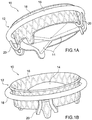
- Fig. 1A and Fig. 1B show a general schematic representation of a prosthetic device for the treatment of heart valves, in accordance with an embodiment of the invention
- FIG. 1A and Fig. 1B show, according to two different perspectives for a better understanding of the drawing, a general schematic representation of an implantable prosthetic device 10 used to replace the function of an atrioventricular valve, in accordance with an embodiment of the invention.
- the prosthetic device 10 as illustrated in Fig. 1A and Fig. 1B , is formed by a prosthetic structure 12 forming a support and interface with the native valve and by a set of flexible prosthetic leaflets 14 fixed to its interior.
- the prosthetic structure 12 is made in a single body, but three conceptually identifiable portions can be seen therein which are different from one another in functional terms. It is in fact possible to identify:
- the prosthetic structure 12 just like each of its elements, is designed in such a way as to be collapsible without repercussions on the safety and functionality of the prosthetic device. It is therefore possible to temporarily reduce the radial size of the prosthesis, in order to allow it to be introduced into the cardiac cavities through small aperture access ports, compatible with the techniques of minimally invasive surgery, or even with the known transcatheteral techniques for positioning and implanting cardiac prostheses.
- the prosthetic device 10 inside a catheter with a small radial profile, capable of conveying the prosthesis inside the cardiac cavity, close to the implantation site, through direct minimally invasive access routes, for example transapically, or via the transluminal route, and effect its deployment and implantation there, functionally replacing the native valve.
- the central support element 16 is the portion of the prosthetic structure which delimits the conduit for the passage of blood through the device. Inside the central support element 16 are fixed the flexible prosthetic leaflets which make the blood flow within the conduit unidirectional. Each prosthetic leaflet 14 does in fact have a sealed edge on the internal surface of the central support element 16, while the opposite edge is free to arrange itself according to the flow pattern inside the prosthetic device 10. Under direct flow conditions, and therefore in the open valve configuration, the prosthetic leaflet 14 flexes substantially in the direction of the flow, with the free edge moving away from the axis of the central support element 16, minimising the obstruction to the flow.
- the prosthetic leaflet 14 positions itself transversally to the direction of the flow, with the free edge of each prosthetic leaflet 14 in contact with the free edge of the contiguous prosthetic leaflets, to entirely occlude the orifice of the conduit.
- the main function of the valve is activated, that is to make the flow within it unidirectional, preventing the reverse flow and minimising the interference with the direct flow.
- Fig. 1A and Fig. 1B there are three prosthetic valve leaflets 14, three being the optimum number of leaflets in a cylindrical orifice. Nevertheless the functioning principle does not change substantially even if there is a lower number of leaflets, for example two, or a number higher than three.
- the central support element 16 is a radially collapsible elastic structure, which tends, due to its elastic recovery, to expand even to a diameter higher than the maximum diameter which maintains the coaptation, that is the contact, between the free margins of the closed prosthetic leaflets 14.
- the containment portion 18 is the portion of the prosthetic structure which contrasts and limits the free expansion of the central support element 16, preventing it from exceeding the maximum diameter compatible with the preservation of the coaptation between the prosthetic leaflets 14.
- the containment portion 18 has a substantially annular geometry and is longitudinally non-extendable, that is it does not significantly change its peripheral extent even when the central support element 16 expands inside it, applying a radial force to the outside.
- the containment portion 18 is disposed outside of the native atrioventricular valve, surrounding the valve leaflets completely, while the central support element 16 is inside the native valve leaflets, substantially on the axis of the orifice of the atrioventricular valve.
- the central support element 16 expands until it meets the containment portion 18, with which it couples on the external surface.
- the containment portion 18 also has the function of stabilising the native valvular annulus, preventing the radial force exerted by the central support element 16, although necessary to guarantee effective anchorage of the prosthesis, from being transferred to the surrounding anatomical structure, which is usually affected by degenerative and dilatory processes associated with the disease which makes the atrioventricular valve malfunction.
- the set of connecting elements 20 is that portion of the prosthetic structure 12 which physically links the central support element 16 and the containment portion 18, making the prosthetic structure 12 a single and continuous entity.
- the monolithic structure allows for safer and effective functioning of the prosthesis, making the anchorage mechanism of the prosthesis stable and durable, as well as simplifying and accelerating the implantation procedure, with immediate and reproducible positioning of the prosthesis, as can be seen from the practical examples described in the following figures.
- the external diameter of the central support element 16 is shown with smaller dimensions than the internal dimensions of the containment portion 18.
- the figures show these two components of the prosthetic structure 12 not in contact with each other in the fully expanded configuration. It is possible to have over-sizing of the central support element 16 compared with the dimensions of the containment portion 18. In this case there is interference between the two portions of the prosthetic structure 12 and in fact the central support element 16 applies radial pressure on the containment portion 18 when the latter exerts its expansion-restraining action, irrespective of the thickness of the tissue which remains entrapped between the two portions of the prosthetic structure 12. This radial pressure increases the stability of anchorage to the native valve leaflets.
- a practical example of this is described below as a prosthesis to replace the mitral valve, the heart valve being positioned between the left atrium and the left ventricle.
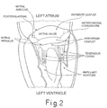
- the anatomical section diagram of the left side of the heart is given in Fig.2 .
- a section in longitudinal axis of the left side of the heart as it would appear if the posterior wall of the ventricle and of the left atrium had been removed. It is therefore possible to visualise the mitral valve in the projection from the posterior arch, with the posterior leaflet in the foreground and the anterior leaflet on the opposite side to the orifice.
- the line of insertion of the leaflets on the plane of the valve identifies the annulus of the mitral valve.
- the zones of the annulus passing between the anterior and the posterior leaflet are indicated as commissural zones.
- the anatomical section chosen also clearly shows the sub-valvular apparatus, consisting of tendinous cords and papillary muscles. This subvalvular apparatus creates continuity between the free margins of the valve leaflets and the walls of the ventricle.
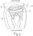
- FIG. 3 shows an example of the application of the prosthetic device 10 described in Fig. 1 , in accordance with a specific embodiment of the invention.
- the illustrative diagram shown in Fig. 3 shows the central support element 16 of the device expanded inside the mitral valve to create the intraprosthetic passage for the blood flow.
- the prosthetic leaflets 14 are inside this passage, with the function of making the flow unidirectional.
- the central support element 16 is inside the native mitral valve
- the containment portion 18 of the prosthesis is positioned on the back of the native leaflets, to surround the mitral valve externally, as a limitative restraint on the expansion of the central support element 16.
- Fig. 3 shows only one of the groups of connecting arms 20, namely the one which passes over the posterior leaflet. A similar arrangement is also created symmetrically on the median portion of the anterior leaflet, remaining hidden in the perspective in Fig. 3 .
- each valve leaflet an aperture is effectively created in the bundles of tendinous cords which depart from the free margins, as shown in Fig.2 for the posterior leaflet.
- Each valve leaflet is in fact connected, by the tendinous cords, to both of the papillary muscles, which are found in positions almost opposite the ventricular cavity.
- This aperture in the combs of the tendinous cords constitutes an excellent passage for the connecting elements 20 of the prosthetic structure.
- the connecting elements 20 contribute to the anchoring of the prosthesis, above all during the critical systolic phase, when the atrioventricular valve is closed and the ventricular pressure, at its maximum, pushes the prosthesis towards the atrium. It is in fact clear how the connecting elements 20, being one with the containment portion 18 segregated on the back of the native leaflets, operate as one structure which securely fastens the central support element 16 to the annulus of the valve, effectively integrating the anchoring action due to the capture and trapping of the native leaflets inside the prosthetic structure itself.
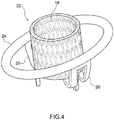
- Fig. 4 shows another version of the prosthetic structure 22, in accordance with a different embodiment of the invention.
- the containment portion 24 of the prosthetic structure maintains an annular and non-extendable form, but has an elongated oval geometry on one axis, an alternative to the substantially circular geometry of the containment portion 18 described in Fig. 1 .
- the prosthetic valve leaflets are not shown, being superfluous for the purposes of the description, and furthermore the central support element 16 is shown in a compressed configuration, as an example of the geometry assumed during the implantation procedure before the final release.
- the connecting elements 20 with arms, the cross section of which has a relatively small thickness (by way of indication and not limited to the range of from 0.25 mm to 0.75 mm) and a significantly larger transverse dimension (for example, still not limitatively, in the range of from 0.5 m to 3 mm).
- the connecting elements 20 prove to be flexible radially, but rigid if loaded tangentially or axiallyx.
- the containment portion 24 having an elongated, oval or bean-shaped, symmetrical or asymmetrical shape, is often more suitable for coupling itself to the anatomical shape of the annulus of the atrioventricular valve, even in the presence of pathological conditions. Indeed during the first phases of the implantation procedure the containment portion 24 of the prosthetic device, already deployed in the ventricular chamber, has to fit substantially with the ventricular aspect of the annulus of the native valve. Indeed positioning the containment portion 24 in close proximity to the line of insertion of the valve leaflets in the annulus ensures both the life of the anchorage, being the thickest and most robust zone of the leaflet, and the complete tightness to counter flow, in that there is continuity of the leaflets along the entire periphery of the valve.
- the geometry adopted by the annular portion during the initial phase of coupling with the native valvular annulus may not affect the final geometry of the expanded prosthetic structure, in particular the shape of the prosthetic orifice, which ensures the best operating conditions for the prosthetic leaflets. It is indeed possible, in accordance with the various embodiments of the invention, to vary, with a considerable degree of freedom, the rigidity to flexion of the containment portion, also creating cross sections with anisotropic elastic characteristics, while still meeting the essential requirement of longitudinal non-extendibility of the portion itself. It is possible to design the annular portion in such a way that it is substantially flexible according to deformations which remain on the plane identified by the element itself, while being substantially rigid for all the direct deformations outside this plane.
- the containment portion cannot be deformed, in the direction of the axis of the prosthesis, during the positioning of the device in the best position for implantation, preventing it from being misaligned with respect to the coupling region on the external surface of the central support element.
- its deformability on the plane allows it to adapt itself perfectly to the expanded geometry of the central support element, thus promoting continuous coupling between the two structures without, moreover, interfering with the correct functioning of the prosthetic leaflets, which requires a pre-defined working geometry of the support element which contains them.
- the containment portion with any oblong geometry suitable for coupling with the native annulus at the time when it is positioned in the subannular groove of the native valve, keeping said containment portion planar during all the positioning phases, owing to its rigidity to deformations outside the plane, and ultimately, when it is implanted, to make it conform to the final cylindrical geometry of the support element, owing to its deformability in the plane.
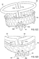
- a containment portion 26 which satisfies the characteristics of an anisotropic elastic response described above is shown in Fig. 5A , as an integral part of the prosthetic structure, and in Fig. 5B , where it is shown in isolated form, for greater clarity.
- the containment portion 26 is formed by a substantially tubular structure, the flexibility of which is regulated by a series of openings 28 having selected dimensions and position. In the example shown in Fig. 5A and 5B , the openings 28 are aligned along two principal generators, one on the internal face and one on the external face of the containment portion 26.
- This rigidity is in accordance with the width of the band.
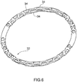
- FIG. 6 Another example of an embodiment of a containment portion 32 is described in Fig. 6 .
- This figure also shows the containment portion 32 isolated from the rest of the prosthetic structure, for greater clarity.
- the containment portion 32 is in tubular form with openings 34 positioned according to a cyclical sequence which reduces the anisotropy of the elastic response of the annular portion, resulting in the openings being more uniformly distributed on the surface. With this geometry too it is possible to modulate the elastic response according to the direction of the flexion.
- Fig. 6 also shows the modulation of the size of the openings 34 according to their angular position on the annular portion, in order to obtain a structure having elastic properties which vary along the periphery according to predetermined requirements.
- Fig. 5 and Fig. 6 refer conceptually to the structural component of the containment portion.
- a structural component can be covered with polymer material, for example silicone or polyurethane, and/or tissue, in order to recreate a continuous and atraumatic external surface.
- polymer material for example silicone or polyurethane, and/or tissue
- tissue both artificial and biological, for the external surface of the containment component also increases its aptitude to be endothelialised and therefore physiologically integrated at the implantation site.
- the sub-valvular structure of the atrioventricular valves creates anatomical and functional continuity between the heart valve and the ventricle wall.
- Each valve leaflet is therefore continuous with the cardiac structure on the one hand through the annulus and on the other through the tendinous cords and papillary muscles. This continuity is important for the stability of the ventricular chamber and it is desirable for the treatment of the valve dysfunction to avoid any interference therewith.
- the requirement to surround the atrioventricular valve externally with the containment portion of the prosthetic structure may be satisfied by providing it with a transitory open configuration, such as to allow it to be positioned in the space between the back of the native leaflets and the ventricle wall, without the need to interrupt the continuity between the ventricle and the valve.
- the open configuration represents a temporary condition associated with its preimplantation positioning behind the native valve, while for the actual implantation phase and under operating conditions the containment portion has a closed and substantially continuous configuration.
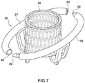
- Fig. 7 shows a version of the prosthetic structure, in accordance with various embodiments of the invention, which provides for a containment portion 36 having a configuration which can go from temporarily open to closed.
- the containment portion 36 is separated into two curved segments 37, 38, each segment 37, 38 being equipped with a mechanism for the reclosing of the annular geometry in a phase subsequent to its positioning on the back of the native valve leaflets.
- this mechanism comprises a shaped pin 39, for example with a saw tooth, facing a cavity 40 having the design and dimensions to prevent the coming out of the shaped pin 39 once this has been inserted into cavity 40.
- the cavity 40 can be designed in such a way as to be radially elastic. In this way it is possible to have slight interference between the shaped pin 39 and the cavity 40, increasing the solidity and reliability of the closure mechanism.
- the closure mechanism can take equivalent alternative shapes.
- the cavity 40 can itself have a saw-tooth profile internally, produced by elastic lamellae (not illustrated) which protrude into the cavity 40.
- the use of super-elastic material for creating the prosthetic structure makes it easier to create deformable structures which improve the effectiveness of the coupling.
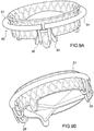
- Fig. 8A and Fig. 8B show another version of the prosthetic structure, which is again in accordance with various embodiments of the invention.
- the solution described in Fig. 8A has a geometry that may prove to be particularly advantageous for implantation on the mitral valve.
- the sub-division of the containment portion 36 is made asymmetrically, replicating, for example, the anatomy of the native valve, where the posterior annular arch 37', that is the one on which the posterior leaflet rests, is longer than the anterior annular arch 38', on which the anterior leaflet rests.
- Fig. 8A also shows an alternative design for the closure mechanism, given in greater detail in Fig. 8B .
- this shaped element 41 has the shape of a sphere 42 connected to the end of the segment by a pin 43 of a smaller diameter than the sphere 42.
- a blind cavity 44 which reproduces, in negative form, the shaping described previously and which is therefore suitable for accommodating and locking the shaped element 41.
- this blind cavity 44 on the external face of the segment, means that the radial force exerted on the containment portion 36 by the central support element 16, following its expansion, contributes to the stability of the coupling, preventing the shaped element 41 from coming out of the corresponding cavity 44 in which it is accommodated.
- the flexibility of the segments of the containment portion facilitates their positioning on the back of the native leaflets. It is indeed possible to considerably amplify the apertures present between the segments of the containment portion, compared with that indicated in Fig. 7 and Fig. 8 purely by way of example, in order to surround the native valve with all the segments.
- Fig. 9A and Fig. 9B a different embodiment is described for the implantable prosthetic device, developed for replacing the function of the atrioventricular valve, in accordance with an embodiment of the invention.
- the containment portion 50 which may have any of the previously described two-dimensional or three-dimensional forms, is subdivided into two or more segments or subcomponents 51 which are separated from one another and obtained by severing the containment portion in line with the connecting elements 20.
- each subcomponent is temporarily separable, using any embodiment of a reversible locking mechanism, from those connecting elements to which, however, it is engaged in the final configuration of the implant.
- the subdivision of the containment portion into two or more subcomponents combined with the possibility of releasing one or more of said subcomponents from the connecting elements on the central support structure make immediate positioning of the containment portion on the back of the native valve leaflets possible during the first phases of the implantation procedure. Then the restoration of the unity of the prosthetic structure, with the recovery of all functional properties, allows final implantation.
- the structural continuity of the containment portion which also ensures the longitudinal non-extendibility of the same and its ability to contrast and limit the radial expansion of the central body, can therefore also be obtained with the contribution of the connecting elements present in the prosthetic structure.
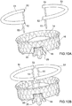
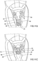
- FIG. 10A an embodiment of the implantable prosthetic device according to the embodiment described above is illustrated in detail in Fig. 10A to Fig. 10C .
- Fig. 10A shows the containment portion 50, of a substantially circular shape for simplicity of representation, subdivided into two subcomponents 51, which are not necessarily symmetrical.
- the continuity of the containment portion 50 is interrupted in line with the connecting elements 20 to the central support element 16.
- Each end 52 of each subcomponent 51 is equipped with a pin 53 preferably orientated outside the annular plane.
- Fig. 10A shows an embodiment in which the pin is orientated substantially perpendicularly to the plane of the annulus.
- the connecting elements 20 are equipped with cylindrical cavities 55 each suitable for accommodating each of these pins.
- a couple of cylindrical seats 55 is present on each of the two groups of connecting elements 22, substantially arranged in angular positions diametrically opposed to the central support element 16.
- cylindrical cavities 55 like the pins 53 present at the ends of the segments 51 of the containment portion 50, can be provided with lamellae, teeth or other surface discontinuities intended to increase the friction in the pin-hole coupling, improving the stability of the connection between the subcomponents 51 of the containment portion 50 and the connecting elements 20.
- the cylindrical seats 55 are orientated in a coherent way to the orientation of the pins 53 present on the subcomponents 51 of the containment portion 50, in such a way that the pin-hole coupling maintains said portion on a geometrically consistent plane with the annulus of the native valve.
- Fig. 10B shows how, once positioned on the back of the native leaflets, the subcomponents 51 of the containment portion 50 can be brought back towards the central element 16 of the prosthetic structure, in such a way that each pin 53 may be substantially aligned with the corresponding cylindrical cavity 55 present on the connecting elements 20 between the two portions.
- Fig. 10C shows the segments 51 of the containment portion 50 reconnected to the central element 16 of the prosthetic structure through the pin-hole couplings created with the connecting elements 20. It can be seen how, in the embodiment described in Fig. 10 , at the end of the process to reconstitute the unity of the prosthetic structure, the containment portion 50 is continuous on all of the periphery of the device and non-extendable longitudinally owing to the presence of short transverse structures 56, an integral part of the connecting elements 20, which unite each couple of cylindrical cavities 55. Only after the unity of the prosthetic structure has been reconstituted, as shown in Fig. 10C , is it possible to proceed with the final positioning of the valvular prosthesis and its implantation.
- Fig.11A to Fig.11G illustrate, purely by way of example, an implantation procedure of the embodiment of the implantable prosthetic device described in Fig. 10 .
- the sequence illustrated in Fig.11 hypothesises a minimally invasive surgical procedure intended to replace the mitral valve, operated on without removing the native valve. Access to the implantation site is through the left atrium with an anterograde approach to the mitral valve, according to the normal practice followed in surgical procedures. It is assumed that the left ventricle is empty and therefore accessible either directly or through endoscopic techniques known at the state of the art, but not necessarily with arrested heart.
- Fig. 11A shows the first step in the procedure, consisting in the positioning, inside the ventricular cavity, of two semi-arched segments which form the subcomponents 51 of the containment portion 50 of the prosthetic structure.
- the subcomponents 51 are introduced into the left ventricle through the mitral valve, with direct manipulation compatible with the surgical approach. Each of them is positioned on the back of a commissural region of the mitral valve, embracing the entire bundle of tendinous cords involving the corresponding half of the valve.
- the orientation of subcomponents 51 is such that the connecting pins 53 are directed towards the apex of the ventricle, that is distally to the operator.
- Surgical access makes it possible to have a direct view, possibly supported by endoscopic instrumentation, of the implantation site and in particular of the inside of the left ventricle. It is therefore possible to check accurately the positioning of the two subcomponents 51, for example as regards their arrangement outside the entire mitral sub-valvular apparatus, before proceeding to the next phase.
- Fig. 11B shows the introduction into the ventricular cavity of the remaining portion of the prosthetic structure, with the central support portion 16 collapsed to its radial diameter of a lesser size and maintained in this configuration using a containing sheath of a release system.
- the connecting elements 20 can be left free outside the sheath of the release system, or they too can be compressed inside the sheath during the introduction operation into the ventricular cavity, in order to have an atraumatic introduction profile and a small profile, to then be selectively released once inside the ventricle.
- Fig.11B shows the free connecting elements 20, in a position at a distance from the subcomponents 51 of the containment portion.
- Fig. 11C shows a first subcomponent 51 of the containment portion 50 reconnected to the central support element16 through the connecting elements 51, using the pin-hole couplings pre-arranged on both parts.
- Fig.11D shows the same operation carried out on the other subcomponent 51 of the containment portion.
- the unity of the prosthetic structure is therefore entirely reconstituted, and the prosthetic device is ready to be implanted.
- the mitral valve, including its subvalvular apparatus is entirely contained between the central support element 16, still in its collapsed configuration to a minimum radial size, and the annular containment portion 50, entirely deployed in the ventricular cavity outside the valve itself.
- Said portions of the prosthetic structure are connected and integrated between them through the connecting elements 20, in accordance with the principal dictated by the present invention and according to the embodiment illustrated in Fig. 1 .
- Fig. 11E and Fig. 11F show how, the unity of the prosthetic structure having been reconstituted, the repositioning of the central support element 16, obtained by the implanter through the release system, involves the automatic repositioning of the containment element 50 too.
- the release system is therefore shifted proximally, in such a way as to reach the correct implantation position.
- the correct implantation position is when the containment portion 50 is in contact with the ventricular aspect of the annulus of the mitral valve, allocated into the so-called subannular groove, while the central element 16 of the prosthetic device is, still in the collapsed configuration, astride the native valve.
- the prosthetic device immediately before final implantation, makes it possible to appreciate how the prosthetic device, conceptually described in Fig.1 , independently of the various embodiments of the invention, is a device able to position itself in the best way without particular skills being required of the operator.
- the structural unity existing between the containment portion 50 and the central support element 16 prevents the prosthesis being arranged in too distal a position (that is too deep into the ventricle) or too proximal a position (that is shifted too much towards the atrium) in relation to the ideal plane of the native annulus.
- the implanter it is in fact sufficient for the implanter to apply slight traction in a proximal direction on the release system to be certain that the containment element 50 is exactly in contact with the valvular annulus and that the correct release position has been reached.
- the impossibility of the containment portion 50 being able to migrate into the atrium, said portion being segregated on the ventricular side of the annulus of the same native mitral valve, does in fact prevent the traction exercised on the release system from generating too proximal a positioning of the prosthetic device.
- Fig. 11G shows the last phase of the implantation procedure, with the release of the central support element 16 and its expansion up to it reaching and coming into contact with the containment portion 50.
- the leaflets of the native mitral valve, entrapped between the two elements of the prosthetic structure, provide for and ensure stable anchoring of the prosthesis and effective tightness to the counterflow of the blood.
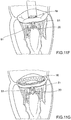
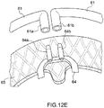
- FIG. 12A A different embodiment of the implantable prosthetic device fully compatible with the use of transcatheteral interventional procedures is illustrated in the figures from Fig. 12A to Fig. 12E .
- Fig. 12A and Fig. 12B show the valvular prosthetic device in a particularly advantageous embodiment for implantation on an atrioventricular valve using transcatheteral techniques.
- a containment portion 60 can, in its entirety, have any two-dimensional or three-dimensional form, according to the anatomy of the healthy or pathological atrioventricular valve, just as it can be subdivided into two or more segments or separate sub-components 61.
- Each sub-component 61 is temporarily separable, using a reversible locking mechanism 62, from those connecting elements 64 to which, on the other hand, it is coupled in the final configuration of the implant.
- Fig. 12C shows the prosthetic device with the sub-components 61 making up the containment portion 60 separated from the central portion 63, in order to make the structure of the reversible locking mechanism 62 of the portions of the prosthesis more visible.
- Fig. 12D and 12E illustrate an enlarged detail of the locking mechanism 62.
- the connecting elements 64 which are integral to the central portion 63 and protrude externally at its periphery, are each equipped with a couple of hollow pins 64a, 64b, which are parallel and adequately spaced apart and are substantially aligned with the axis of the prosthetic device itself.
- the number of connecting elements 64 is equivalent to the number of sub-components 61 in which the containment portion 60 of the prosthesis is subdivided in such a way as to allow the continuity of the containment portion 60 itself to be reconstituted by using the connecting elements 64. As shown in Fig.
- each pin 64a, 64b of the same sub-component 61 is hollow and therefore allows a guidewire to pass freely inside it, as will be more clearly described below.
- each end 61a, 61b of each sub-component 61 of the containment portion 60 also consists of a, preferably but not restricted to, substantially cylindrical hollow structure, as shown in Fig. 12E , suitable not only for the free passage of a guidewire, but also having dimensions such as to allow stable coupling with the corresponding pin 64a, 64b present on the connecting element 64.
- the hollow ends 61a, 61b of each sub-component 61 of the containment portion 64 are orientated substantially perpendicularly to a principal plane of the sub-component itself. In this way, the containment portion 60, in its entirety, is parallel to the annular plane of the native valve once the structural unity of the valvular prosthetic device has been reconstituted.
- Both the cylindrical cavities present at the ends 61a, 61b of the sub-components 61 of the containment portion 60 and the pins 64a, 64b present on the connecting elements 64 can be provided with lamellae or teeth or other surface discontinuities suitable for increasing the friction in the pin-hole coupling, improving the stability of the mutual connection.
- each sub-component 61 of the containment portion 60 can provide a passage for a guidewire 65', 65" along all or at least most of its length. In this way it will be easier to position the sub-component 61 inside the ventricular cavity on the back of the native valve leaflets. It is, in fact, enough to arrange the guidewire 65', 65", using well-known interventional techniques currently used in clinical use, along the path which identifies the desired positioning of the sub-component 61 and introduce said sub-component so that it runs along the guidewire 65', 65" itself.
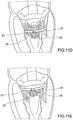
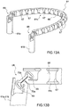
- Fig. 13A to Fig. 13E show a possible embodiment of sub-component 61, in which the containment portion 60 is sub-divided, which is particularly suitable for an implantation procedure carried out by means of transcatheteral techniques.
- Fig. 13A shows, for representational simplicity, only the structural part of the sub-components 61 comprising the containment portion 60 of the prosthetic device.
- the structural part is obtained substantially from a tubular element 66 on the wall of which openings 67 have been made and are appropriately sized and positioned and suitable for providing the structure with the desired elastic behaviour, which can be anisotropic and variable from section to section, according to the position along the path of the sub-component 61.
- the structure of the sub-component 61 is shaped as shown schematically in Fig.
- the central section 61c is curved consistently with the geometry chosen for the containment portion 60, while the ends 61a, 61b are substantially deflected at right angle in respect of the central section 61c of the sub-component 61.
- the final shape of the sub-component 61 such as the shape shown in Fig. 13A , can be assigned to it in the production phase using suitable heat treatments applied to the piece held inside a mould.
- the two ends 61a, 61b of a preferably cylindrical shape are clearly identifiable, substantially deflected at right angle in respect of the main plane of the structure of the central section 61c.
- These ends 61a, 61b comprise the elements of the sub-component 61 that form part of the connection mechanism to the central portion 63 of the prosthetic device.
- ends 61a, 61b are connected to the central section 61c of the structure of the sub-component 61 through a transition zone 68 which acts as a unidirectional joint, allowing in one way the realignment of the ends on the same plane of the remaining portion of the sub-component 61, but, in the opposite direction, preventing a major deflection of 90° between the main plane of the sub-component 61 and the axis of the prosthetic device, once the sub-component 61 has been connected to the central portion 63 of the prosthetic device.
- This functional requirement avoids the risk of a deflection of the sub-components 61 of the containment portion 60 towards the inside of the ventricular chamber. In this way both the continuity of the contact of the containment portion 60 on the annulus of the native valve, and the correct mutual alignment between the containment portion 60 and the central portion 63 are guaranteed at the time of the final release of the prosthetic device.
- Fig. 13B and Fig. 13C illustrate by way of example, without limiting the general nature of the invention in doing so, an embodiment of said unilateral joint 68.
- the end 61a, 61b of the sub-component 61 is connected to the rest of the structure 61c by a couple of coils 69, created directly in the wall of the tubular body 66, shaped in such a way as to act as a angular spring.
- This solution is compatible with the working processes of the sub-component 61 described previously.
- Fig. 13B shows the bent, that is operational, configuration of the joint section 68.
- the lower surfaces 70a, 70b of the two sections of the tubular body adjacent to the joint 68 are cut at an angle in such a way that in the configuration deflected to 90° they come into contact with each other and at the same time the elastic coil 69 is closed as a package.
- the two aspects combined prevent the further deflection of the end 61a, 61b compared with the central section 61c of the structure of the sub-component 61.
- Fig. 13C shows the straightened configuration of the joint section 68.
- the surfaces of the two sections 70a, 70b previously in contact are separated, and the joining elastic coils 69 are open.
- the geometry of the elastic coil 69 is such that the deformation is distributed in a substantially uniform manner, avoiding concentrations of stress in the material.
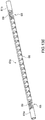
- Fig, 13D and Fig. 13E show how the combined effect of the mesh design of the structure 66 and of the elastic joint 68 introduced near the ends 61a, 61b allows the sub-component 61 to assume a substantially straight shape, particularly suitable for its implantation using transcatheteral techniques.
- Fig. 13D shows the straightening of the ends 61a, 61b, made possible by the elastic joint 68, a possible embodiment of which is illustrated in Fig. 13B and Fig. 13C .
- Fig. 13E shows the straight configuration of the sub-component 61 made possible by the mesh design of the central section 61c of sub-component 61.
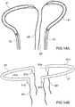
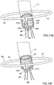
- Fig. 14A to Fig, 14E illustrate a possible transcatheteral implantation procedure of the embodiment of the implantable prosthetic device described in Fig. 12 , including the connection of the containment portion 60 to the central portion of the prosthesis 63 in ways compatible with a totally transcatheteral interventional procedure.
- the depiction of the native atrioventricular valve is omitted.
- a wholly analogous procedure can also be carried out in the case in which the containment portion is sub-divided into a greater number of sub-components.
- Fig. 14A shows the positioning, in outline, using catheters 70 with a low radial profile, of the sub-components 61 of the containment portion 60 of the prosthesis on the back of the leaflets of the native atrioventricular valve.
- guidewires 65', 65" are used, one for each sub-component 61, which have been arranged beforehand in line with the final position required for the sub-components 61 themselves. It is in fact a well-known technique in the current state of the art of cardiac interventional procedures of how to navigate a guidewire inside the chambers of the heart.
- Fig. 14B shows how, once the sub-component 61 has been taken to its optimum position for implantation, the catheter 70, which has conveyed it, will be removed, nevertheless leaving the guidewire 65', 65" in situ, that is through the structure 66 of the sub-component 61 and with both ends accessible to the operator. Released from the catheter sheath 70, the sub-component 61 regains its original configuration having the curvature of the central section 61c itself and its ends 61a, 61b deflected in respect of the plane of the central section 61c.
- Fig. 14C shows the central portion 63 of the prosthesis, collapsed to its smaller radial diameter, being maintained in this configuration inside a release system 71, with the free ends of the guidewires 65', 65" inserted in the passages for the wires present inside each pin 64a, 64b of each sub-component 61 of the connecting mechanism 64.
- each guidewire 65', 65" connects a couple of pins 64a, 64b which are integral to the central body 63 of the prosthesis and positioned on two separate and adjacent connecting elements 64, to the two ends 61a, 61b of the corresponding sub-component 61 of the containment portion 60.
- Fig. 14D shows the central portion 63 of the prosthesis, still in the collapsed configuration inside the release system 71, introduced inside the cardiac cavity in order to reach the implantation position.
- Fig. 14E shows how the tensioning of the guidewires 65', 65" brings the ends 61a, 61b of the sub-components 61 of the containment portion 60 together and aligns them with the corresponding pins 64a, 64b which are integral to the connecting elements 64.
- Fig. 14F shows how the further tensioning of the guidewires 65', 65" works the mechanical coupling between the ends 61a, 61b of the sub-components 61 of the containment portion 60 and the pins 64a, 64b which are integral to the connecting elements 64.
- both the structural continuity of the containment portion 60 and the unicity of the prosthetic device are reconstituted.
- Fig. 14G finally shows the release of the central portion 63 and its expansion up to where it approaches and comes into contact with the containment portion 60. This being the final phase of the implantation procedure of the valvular prosthesis, both the guidewires 65', 65" and the release system 71 of the central portion 63 of the prosthesis can be removed from the cardiac chambers.
Claims (17)
- Dispositif prothétique pour une valvule cardiaque, comprenant :- une partie de valvule (16, 63) avec des feuillets prothétiques (14) capables de reproduire la fonction des feuillets de valvule d'une valvule cardiaque native, pouvant être déployée d'une configuration affaissée pour l'implantation dans une configuration déployée de travail,- une partie de rétention (18, 24, 32, 36, 51, 61) qui entoure la partie de valvule (16, 63) de manière à retenir et limiter son déploiement dans la configuration déployée de travail, la partie de rétention étant sensiblement non extensible longitudinalement,- une partie de connexion (20) qui connecte de manière stable la partie de valvule (16) à la partie de rétention (18, 24, 32, 36, 51, 61) par le biais d'éléments de connexion (53, 55, 64) lorsque la partie de valvule (16) est dans la configuration affaissée.
- Dispositif prothétique selon la revendication 1, dans lequel la partie de valvule (16, 63) comprend un élément de support (16, 63) destiné à supporter la totalité des feuillets prothétiques (14), les éléments de connexion (53, 55, 64) de la partie de connexion (20) comprenant des éléments flexibles pour la connexion physique et l'unité structurelle entre l'élément de support (16, 63) de la partie de valvule (16, 63) et la partie de rétention (18, 24, 32, 36, 51, 61).
- Dispositif prothétique selon la revendication 1 ou la revendication 2, dans lequel la partie de rétention (18, 24, 32, 36, 51, 61) est une structure avec une géométrie bidimensionnelle ou tridimensionnelle qui est sensiblement annulaire en vue de dessus.
- Dispositif prothétique selon la revendication 3, dans lequel la partie de rétention (18, 24, 32, 36, 51, 61) peut être assemblée de manière sélective depuis une configuration ouverte, appropriée pour permettre son insertion au dos des feuillets de valvule natifs, jusqu'à la configuration fermée sensiblement annulaire.
- Dispositif prothétique selon la revendication 4, dans lequel la partie de rétention (18, 24, 32, 36, 51, 61) comprend une pluralité de segments (51, 61) comprenant chacun des moyens de connexion (53, 61a, 61b) pour la reconstruction assemblée de la continuité annulaire de la partie de rétention (18, 24, 32, 36, 51, 61).
- Dispositif prothétique selon la revendication 4 ou la revendication 5, dans lequel les moyens de connexion comprennent un ou plusieurs éléments de connexion (53, 55, 64) de la partie de connexion (20) .
- Dispositif prothétique selon la revendication 5 ou la revendication 6, dans lequel certains ou la totalité des segments (51, 61) peuvent être séparés temporairement de la partie de valvule (16, 63).
- Dispositif prothétique selon l'une quelconque des revendications précédentes, dans lequel la partie de rétention (18, 24, 32, 36, 51, 61) est en même temps flexible par rapport à des déformations qui se produisent dans le plan identifié par la partie de rétention (18, 24, 32, 36, 51, 61) elle-même et sensiblement rigide par rapport à une déformation directe à l'extérieur de ce plan.
- Dispositif prothétique selon l'une quelconque des revendications précédentes, dans lequel au moins une partie de la partie de rétention (18, 24, 32, 36, 51, 61) est recouverte par des tissus de type biologique ou artificiel ou avec un matériau polymère, ou une combinaison de ceux-ci.
- Dispositif prothétique selon l'une quelconque des revendications précédentes, comprenant un mécanisme de verrouillage compatible avec des technologies transcathéter, dans lequel la partie de rétention (18, 24, 32, 36, 51, 61) est subdivisée en sous-composants (51, 61) pour lui permettre d'être positionnée au dos des feuillets de la valvule atrio-ventriculaire native, le mécanisme de verrouillage comprenant une ou plusieurs structures (61a, 61b) de la partie de rétention (18, 24, 32, 36, 51, 61) qui peuvent être alignées et accouplées de manière stable à une ou plusieurs structures (64a, 64b) de la partie de valvule (16, 63) en utilisant un fil-guide (65', 65").
- Dispositif prothétique selon la revendication 10, dans lequel les fils-guides (65', 65") sont connectés à chacune d'une ou plusieurs structures (61a, 61b) de la partie de rétention (18, 24, 32, 36) et à chacune d'une ou plusieurs structures (64a, 64b) de la partie de valvule (16, 63).
- Dispositif prothétique selon la revendication 11, dans lequel une ou plusieurs structures de la partie de rétention (18, 24, 32, 36, 51, 61) et une ou plusieurs structures de la partie de valvule (16, 63) comprennent des organes creux (61a, 61b ; 64a, 64b) aptes à permettre aux fils-guides (65', 65") de passer à travers eux.
- Dispositif prothétique selon l'une quelconque des revendications 10 à 12, dans lequel la partie de valvule (16, 63) présente, sur sa périphérie, des structures creuses (64a, 64b) appropriées pour le passage d'un ou plusieurs fils-guides (65', 65") appropriés pour réaliser un accouplement mécanique stable avec des structures creuses correspondantes (61a, 61b) présentes sur la partie de rétention (18, 24, 32, 36).
- Dispositif prothétique selon l'une quelconque des revendications 10 à 13, dans lequel chaque sous-composant de la partie de rétention (18, 24, 32, 36) présente des mécanismes communs qui leur permettent d'être déformés élastiquement jusqu'à ce qu'ils adoptent une configuration occupant un espace radial réduit par rapport à une configuration déployée de travail.
- Procédé pour assembler un dispositif prothétique pour une valvule cardiaque, comprenant les étapes suivantes :- fournir une partie de valvule (16, 63) dans une configuration affaissée, la partie de valvule (16, 63) ayant des feuillets prothétiques (14) capables de reproduire la fonction des feuillets de valvule d'une valvule cardiaque native, la partie de valvule (16, 63) pouvant être déployée d'une configuration affaissée pour l'implantation dans une configuration déployée de travail,- fournir une partie de rétention (18, 24, 32, 36, 51, 61) qui entoure la partie de valvule (16, 63) de manière à retenir et limiter son déploiement dans la configuration déployée de travail, la partie de rétention étant sensiblement non extensible longitudinalement,- connecter de manière stable la partie de valvule (16, 63) à la partie de rétention (18, 24, 32, 36, 51, 61) au moyen d'une partie de connexion (20) par le biais d'éléments de connexion (53, 55, 64) lorsque la partie de valvule (16, 63) est dans la configuration affaissée.
- Procédé pour assembler un dispositif prothétique selon la revendication 15, dans lequel la partie de rétention (18, 24, 32, 36, 51, 61) peut être assemblée de manière sélective d'une configuration ouverte jusqu'à une configuration fermée sensiblement annulaire.
- Procédé pour assembler un dispositif prothétique selon la revendication 16, dans lequel la partie de rétention (18, 24, 32, 36, 51, 61) comprend une pluralité de segments comprenant chacun des moyens de connexion pour la reconstruction assemblée de la continuité annulaire de la partie de rétention (18, 24, 32, 36, 51, 61).
Priority Applications (2)
| Application Number | Priority Date | Filing Date | Title |
|---|---|---|---|
| EP19192704.5A EP3590473A1 (fr) | 2014-02-04 | 2015-02-04 | Dispositif de prothèse pour valvule cardiaque |
| PL15710894T PL3102152T3 (pl) | 2014-02-04 | 2015-02-04 | Urządzenie protetyczne dla zastawki serca |
Applications Claiming Priority (3)
| Application Number | Priority Date | Filing Date | Title |
|---|---|---|---|
| ITBO20140050 | 2014-02-04 | ||
| ITBO20150040 | 2015-01-30 | ||
| PCT/IB2015/050849 WO2015118464A1 (fr) | 2014-02-04 | 2015-02-04 | Dispositif de prothèse pour valvule cardiaque |
Related Child Applications (1)
| Application Number | Title | Priority Date | Filing Date |
|---|---|---|---|
| EP19192704.5A Division EP3590473A1 (fr) | 2014-02-04 | 2015-02-04 | Dispositif de prothèse pour valvule cardiaque |
Publications (2)
| Publication Number | Publication Date |
|---|---|
| EP3102152A1 EP3102152A1 (fr) | 2016-12-14 |
| EP3102152B1 true EP3102152B1 (fr) | 2019-08-21 |
Family
ID=52692992
Family Applications (2)
| Application Number | Title | Priority Date | Filing Date |
|---|---|---|---|
| EP19192704.5A Pending EP3590473A1 (fr) | 2014-02-04 | 2015-02-04 | Dispositif de prothèse pour valvule cardiaque |
| EP15710894.5A Active EP3102152B1 (fr) | 2014-02-04 | 2015-02-04 | Dispositif de prothèse pour valvule cardiaque |
Family Applications Before (1)
| Application Number | Title | Priority Date | Filing Date |
|---|---|---|---|
| EP19192704.5A Pending EP3590473A1 (fr) | 2014-02-04 | 2015-02-04 | Dispositif de prothèse pour valvule cardiaque |
Country Status (11)
| Country | Link |
|---|---|
| US (2) | US11123179B2 (fr) |
| EP (2) | EP3590473A1 (fr) |
| JP (3) | JP7126807B2 (fr) |
| KR (2) | KR102577607B1 (fr) |
| AU (1) | AU2015215634B2 (fr) |
| BR (1) | BR112016017196B1 (fr) |
| CA (2) | CA3160505A1 (fr) |
| DK (1) | DK3102152T3 (fr) |
| ES (1) | ES2755938T3 (fr) |
| PL (1) | PL3102152T3 (fr) |
| WO (1) | WO2015118464A1 (fr) |
Cited By (13)
| Publication number | Priority date | Publication date | Assignee | Title |
|---|---|---|---|---|
| US10856984B2 (en) | 2017-08-25 | 2020-12-08 | Neovasc Tiara Inc. | Sequentially deployed transcatheter mitral valve prosthesis |
| US10940001B2 (en) | 2012-05-30 | 2021-03-09 | Neovasc Tiara Inc. | Methods and apparatus for loading a prosthesis onto a delivery system |
| US11311376B2 (en) | 2019-06-20 | 2022-04-26 | Neovase Tiara Inc. | Low profile prosthetic mitral valve |
| US11357622B2 (en) | 2016-01-29 | 2022-06-14 | Neovase Tiara Inc. | Prosthetic valve for avoiding obstruction of outflow |
| US11389291B2 (en) | 2013-04-04 | 2022-07-19 | Neovase Tiara Inc. | Methods and apparatus for delivering a prosthetic valve to a beating heart |
| US11413139B2 (en) | 2011-11-23 | 2022-08-16 | Neovasc Tiara Inc. | Sequentially deployed transcatheter mitral valve prosthesis |
| US11419720B2 (en) | 2010-05-05 | 2022-08-23 | Neovasc Tiara Inc. | Transcatheter mitral valve prosthesis |
| US11464631B2 (en) | 2016-11-21 | 2022-10-11 | Neovasc Tiara Inc. | Methods and systems for rapid retraction of a transcatheter heart valve delivery system |
| US11491006B2 (en) | 2019-04-10 | 2022-11-08 | Neovasc Tiara Inc. | Prosthetic valve with natural blood flow |
| US11497602B2 (en) | 2012-02-14 | 2022-11-15 | Neovasc Tiara Inc. | Methods and apparatus for engaging a valve prosthesis with tissue |
| US11602429B2 (en) | 2019-04-01 | 2023-03-14 | Neovasc Tiara Inc. | Controllably deployable prosthetic valve |
| US11737872B2 (en) | 2018-11-08 | 2023-08-29 | Neovasc Tiara Inc. | Ventricular deployment of a transcatheter mitral valve prosthesis |
| US11779742B2 (en) | 2019-05-20 | 2023-10-10 | Neovasc Tiara Inc. | Introducer with hemostasis mechanism |
Families Citing this family (72)
| Publication number | Priority date | Publication date | Assignee | Title |
|---|---|---|---|---|
| US8323335B2 (en) | 2008-06-20 | 2012-12-04 | Edwards Lifesciences Corporation | Retaining mechanisms for prosthetic valves and methods for using |
| PL3335670T3 (pl) | 2010-03-05 | 2022-09-05 | Edwards Lifesciences Corporation | Mechanizmy ustalające do zastawek protetycznych |
| US8657872B2 (en) | 2010-07-19 | 2014-02-25 | Jacques Seguin | Cardiac valve repair system and methods of use |
| EP2595569A4 (fr) | 2010-07-23 | 2016-02-24 | Edwards Lifesciences Corp | Mécanismes de rétention pour prothèses valvulaires |
| AU2012272855C1 (en) | 2011-06-21 | 2018-04-05 | Twelve, Inc. | Prosthetic heart valve devices and associated systems and methods |
| US9387075B2 (en) * | 2011-09-12 | 2016-07-12 | Highlife Sas | Transcatheter valve prosthesis |
| EP2750630B1 (fr) | 2011-10-19 | 2021-06-30 | Twelve, Inc. | Dispositif de remplacement de valvule cardiaque |
| US10016271B2 (en) | 2011-10-19 | 2018-07-10 | Twelve, Inc. | Prosthetic heart valve devices, prosthetic mitral valves and associated systems and methods |
| US9039757B2 (en) | 2011-10-19 | 2015-05-26 | Twelve, Inc. | Prosthetic heart valve devices, prosthetic mitral valves and associated systems and methods |
| US11202704B2 (en) | 2011-10-19 | 2021-12-21 | Twelve, Inc. | Prosthetic heart valve devices, prosthetic mitral valves and associated systems and methods |
| JP6049761B2 (ja) | 2012-01-31 | 2016-12-21 | マイトラル・ヴァルヴ・テクノロジーズ・エス・アー・エール・エル | 僧帽弁ドッキングデバイス、システム、および方法 |
| US9427315B2 (en) | 2012-04-19 | 2016-08-30 | Caisson Interventional, LLC | Valve replacement systems and methods |
| US9011515B2 (en) | 2012-04-19 | 2015-04-21 | Caisson Interventional, LLC | Heart valve assembly systems and methods |
| ES2864087T3 (es) | 2013-08-14 | 2021-10-13 | Mitral Valve Tech Sarl | Aparato de válvula cardíaca de sustitución |
| US9050188B2 (en) | 2013-10-23 | 2015-06-09 | Caisson Interventional, LLC | Methods and systems for heart valve therapy |
| CA2938468C (fr) | 2014-02-20 | 2023-09-12 | Mitral Valve Technologies Sarl | Ancrage helicoidal pour maintenir une valvule cardiaque prothetique, valvule cardiaque prothetique, et dispositif de deploiement |
| JP2017506119A (ja) | 2014-02-21 | 2017-03-02 | マイトラル・ヴァルヴ・テクノロジーズ・エス・アー・エール・エル | 人工僧帽弁およびアンカーデバイスを送達するためのデバイス、システム、および方法 |
| US9974647B2 (en) | 2014-06-12 | 2018-05-22 | Caisson Interventional, LLC | Two stage anchor and mitral valve assembly |
| US10016272B2 (en) | 2014-09-12 | 2018-07-10 | Mitral Valve Technologies Sarl | Mitral repair and replacement devices and methods |
| US9750607B2 (en) | 2014-10-23 | 2017-09-05 | Caisson Interventional, LLC | Systems and methods for heart valve therapy |
| US9750605B2 (en) | 2014-10-23 | 2017-09-05 | Caisson Interventional, LLC | Systems and methods for heart valve therapy |
| US10231834B2 (en) * | 2015-02-09 | 2019-03-19 | Edwards Lifesciences Corporation | Low profile transseptal catheter and implant system for minimally invasive valve procedure |
| US10631977B2 (en) * | 2015-08-24 | 2020-04-28 | Edwards Lifesciences Corporation | Covering and assembly method for transcatheter valve |
| ITUB20159133A1 (it) | 2015-12-15 | 2017-06-15 | Innovheart S R L | Protesi per valvola cardiaca |
| WO2017117388A1 (fr) | 2015-12-30 | 2017-07-06 | Caisson Interventional, LLC | Systèmes et méthodes pour thérapie de valvule cardiaque |
| US11833034B2 (en) | 2016-01-13 | 2023-12-05 | Shifamed Holdings, Llc | Prosthetic cardiac valve devices, systems, and methods |
| US10363130B2 (en) | 2016-02-05 | 2019-07-30 | Edwards Lifesciences Corporation | Devices and systems for docking a heart valve |
| US10828150B2 (en) * | 2016-07-08 | 2020-11-10 | Edwards Lifesciences Corporation | Docking station for heart valve prosthesis |
| CR20190069A (es) | 2016-08-26 | 2019-05-14 | Edwards Lifesciences Corp | Valvulas y sistemas de acoplamiento de valvulas corazon |
| US10722359B2 (en) | 2016-08-26 | 2020-07-28 | Edwards Lifesciences Corporation | Heart valve docking devices and systems |
| CN114617677A (zh) | 2016-12-20 | 2022-06-14 | 爱德华兹生命科学公司 | 用于部署用于置换心脏瓣膜的对接装置的系统和机构 |
| US11185406B2 (en) | 2017-01-23 | 2021-11-30 | Edwards Lifesciences Corporation | Covered prosthetic heart valve |
| US11654023B2 (en) | 2017-01-23 | 2023-05-23 | Edwards Lifesciences Corporation | Covered prosthetic heart valve |
| US11013600B2 (en) | 2017-01-23 | 2021-05-25 | Edwards Lifesciences Corporation | Covered prosthetic heart valve |
| USD867595S1 (en) | 2017-02-01 | 2019-11-19 | Edwards Lifesciences Corporation | Stent |
| US10702378B2 (en) | 2017-04-18 | 2020-07-07 | Twelve, Inc. | Prosthetic heart valve device and associated systems and methods |
| US10842619B2 (en) | 2017-05-12 | 2020-11-24 | Edwards Lifesciences Corporation | Prosthetic heart valve docking assembly |
| US10709591B2 (en) | 2017-06-06 | 2020-07-14 | Twelve, Inc. | Crimping device and method for loading stents and prosthetic heart valves |
| AU2018291171B2 (en) | 2017-06-30 | 2023-11-30 | Edwards Lifesciences Corporation | Lock and release mechanisms for trans-catheter implantable devices |
| SG11201912180QA (en) | 2017-06-30 | 2020-01-30 | Edwards Lifesciences Corp | Docking stations transcatheter valves |
| US10786352B2 (en) | 2017-07-06 | 2020-09-29 | Twelve, Inc. | Prosthetic heart valve devices and associated systems and methods |
| US10729541B2 (en) | 2017-07-06 | 2020-08-04 | Twelve, Inc. | Prosthetic heart valve devices and associated systems and methods |
| US11291820B2 (en) | 2017-07-24 | 2022-04-05 | Innovheart S.R.L. | Valve assembly with sealing capability for instruments and/or guide wires for use as access/tool port |
| USD890333S1 (en) | 2017-08-21 | 2020-07-14 | Edwards Lifesciences Corporation | Heart valve docking coil |
| WO2019195860A2 (fr) | 2018-04-04 | 2019-10-10 | Vdyne, Llc | Dispositifs et procédés d'ancrage d'une valvule cardiaque transcathéter |
| US11344413B2 (en) | 2018-09-20 | 2022-05-31 | Vdyne, Inc. | Transcatheter deliverable prosthetic heart valves and methods of delivery |
| US10321995B1 (en) | 2018-09-20 | 2019-06-18 | Vdyne, Llc | Orthogonally delivered transcatheter heart valve replacement |
| US10595994B1 (en) | 2018-09-20 | 2020-03-24 | Vdyne, Llc | Side-delivered transcatheter heart valve replacement |
| US11278437B2 (en) | 2018-12-08 | 2022-03-22 | Vdyne, Inc. | Compression capable annular frames for side delivery of transcatheter heart valve replacement |
| US11071627B2 (en) | 2018-10-18 | 2021-07-27 | Vdyne, Inc. | Orthogonally delivered transcatheter heart valve frame for valve in valve prosthesis |
| JP2022504241A (ja) | 2018-10-05 | 2022-01-13 | シファメド・ホールディングス・エルエルシー | 人工心弁デバイス、システム、および方法 |
| US11109969B2 (en) | 2018-10-22 | 2021-09-07 | Vdyne, Inc. | Guidewire delivery of transcatheter heart valve |
| US11253359B2 (en) | 2018-12-20 | 2022-02-22 | Vdyne, Inc. | Proximal tab for side-delivered transcatheter heart valves and methods of delivery |
| US11273032B2 (en) | 2019-01-26 | 2022-03-15 | Vdyne, Inc. | Collapsible inner flow control component for side-deliverable transcatheter heart valve prosthesis |
| US11185409B2 (en) | 2019-01-26 | 2021-11-30 | Vdyne, Inc. | Collapsible inner flow control component for side-delivered transcatheter heart valve prosthesis |
| WO2020181154A2 (fr) | 2019-03-05 | 2020-09-10 | Vdyne, Inc. | Dispositifs de régulation de régurgitation tricuspide pour prothèse de valvule cardiaque transcathéter orthogonale |
| US11173027B2 (en) | 2019-03-14 | 2021-11-16 | Vdyne, Inc. | Side-deliverable transcatheter prosthetic valves and methods for delivering and anchoring the same |
| US11076956B2 (en) | 2019-03-14 | 2021-08-03 | Vdyne, Inc. | Proximal, distal, and anterior anchoring tabs for side-delivered transcatheter mitral valve prosthesis |
| EP3941391A4 (fr) | 2019-03-19 | 2022-11-23 | Shifamed Holdings, LLC | Dispositifs, systèmes et procédés pour valvule cardiaque prothétique |
| US11452599B2 (en) | 2019-05-02 | 2022-09-27 | Twelve, Inc. | Fluid diversion devices for hydraulic delivery systems and associated methods |
| JP2022530764A (ja) | 2019-05-04 | 2022-07-01 | ブイダイン,インコーポレイテッド | 生来の弁輪での側方送達される人工心臓弁を展開するための締め付けデバイス及び方法 |
| AU2020319150A1 (en) * | 2019-07-25 | 2022-02-10 | Innovheart S.R.L. | Device for implanting a prosthesis for a heart valve and assembly procedure |
| US11517425B2 (en) | 2019-07-25 | 2022-12-06 | Innovheart S.R.L. | Device for implanting a prosthesis for a heart valve and assembly procedure |
| US11684473B2 (en) | 2019-07-25 | 2023-06-27 | Innovheart S.R.L. | Device for arranging guidewires around a heart valve |
| EP4017442A4 (fr) | 2019-08-20 | 2023-07-26 | Vdyne, Inc. | Dispositifs d'administration et de récupération et procédés pour valvules prothétiques transcathéter à pose latérale |
| CN114630665A (zh) | 2019-08-26 | 2022-06-14 | 维迪内股份有限公司 | 可侧面输送的经导管假体瓣膜及其输送和锚定方法 |
| US20220401214A1 (en) * | 2019-10-30 | 2022-12-22 | Shifamed Holdings, Llc | Prosthetic cardiac valve delivery devices, systems, and methods |
| US11234813B2 (en) | 2020-01-17 | 2022-02-01 | Vdyne, Inc. | Ventricular stability elements for side-deliverable prosthetic heart valves and methods of delivery |
| JP2023544825A (ja) * | 2020-10-07 | 2023-10-25 | ザ チルドレンズ メディカル センター コーポレーション | エンジニアリング設計に基づいた弁再構築のワークフロー |
| CN113730036A (zh) * | 2021-09-30 | 2021-12-03 | 宁波健世科技股份有限公司 | 一种可与自体瓣叶锚定的心脏瓣膜假体 |
| WO2023144688A1 (fr) * | 2022-01-25 | 2023-08-03 | Innovheart S.R.L. | Prothèse pour valvule cardiaque et procédé de construction d'un composant de celle-ci |
| WO2023228138A1 (fr) * | 2022-05-26 | 2023-11-30 | Innovheart S.R.L. | Prothèse de valve dotée d'un élément de retenue pivotant |
Citations (16)
| Publication number | Priority date | Publication date | Assignee | Title |
|---|---|---|---|---|
| US6733525B2 (en) | 2001-03-23 | 2004-05-11 | Edwards Lifesciences Corporation | Rolled minimally-invasive heart valves and methods of use |
| US20070100439A1 (en) | 2005-10-31 | 2007-05-03 | Medtronic Vascular, Inc. | Chordae tendinae restraining ring |
| US7753949B2 (en) | 2007-02-23 | 2010-07-13 | The Trustees Of The University Of Pennsylvania | Valve prosthesis systems and methods |
| US20120022633A1 (en) | 2010-07-23 | 2012-01-26 | Christopher Olson | Retaining mechanisms for prosthetic valves |
| US20120123531A1 (en) | 2010-08-04 | 2012-05-17 | Micardia Corporation | Percutaneous transcatheter repair of heart valves |
| US20120165930A1 (en) | 2010-12-23 | 2012-06-28 | The Foundy, Llc | System for mitral valve repair and replacement |
| WO2013021374A2 (fr) | 2011-08-05 | 2013-02-14 | Mitraltech Ltd. | Techniques pour le remplacement et la fixation percutanés d'une valvule mitrale |
| WO2013021375A2 (fr) | 2011-08-05 | 2013-02-14 | Mitraltech Ltd. | Remplacement et fixation percutanés d'une valvule mitrale |
| WO2013095816A1 (fr) | 2011-12-21 | 2013-06-27 | Edwards Lifesciences Corporation | Dispositif d'ancrage et procédé pour remplacer ou réparer une valve cardiaque |
| WO2013110722A2 (fr) | 2012-01-24 | 2013-08-01 | Medtentia International Ltd Oy | Agencement, support en forme de boucle, valvule cardiaque prothétique et procédé de réparation ou de remplacement d'une valvule cardiaque native |
| WO2013175468A2 (fr) * | 2012-05-20 | 2013-11-28 | Tel Hashomer Medical Research Infrastructure And Services Ltd. | Valvule mitrale prosthétique |
| WO2014081796A1 (fr) | 2012-11-21 | 2014-05-30 | Edwards Lifesciences Corporation | Mécanismes de retenue pour valvules cardiaques prothétiques |
| US20140200662A1 (en) | 2013-01-16 | 2014-07-17 | Mvalve Technologies Ltd. | Anchoring elements for intracardiac devices |
| WO2014189509A1 (fr) | 2013-05-22 | 2014-11-27 | Nadav Yellin | Valve transcathéter prothétique pour remplacement de valve mitrale ou tricuspide |
| WO2015023862A2 (fr) | 2013-08-14 | 2015-02-19 | Mitral Valve Technologies Sa | Appareil de valve cardiaque de remplacement et procédés |
| US20150073537A1 (en) | 2013-07-09 | 2015-03-12 | Edwards Lifesciences Corporation | Collapsible cardiac implant and deployment system and methods |
Family Cites Families (27)
| Publication number | Priority date | Publication date | Assignee | Title |
|---|---|---|---|---|
| ATE449581T1 (de) | 1997-12-29 | 2009-12-15 | The Cleveland Clinic Foundation | System zur minimalinvasiven einführung einer herzklappen- bioprothese |
| US6419696B1 (en) | 2000-07-06 | 2002-07-16 | Paul A. Spence | Annuloplasty devices and related heart valve repair methods |
| US7959674B2 (en) | 2002-07-16 | 2011-06-14 | Medtronic, Inc. | Suture locking assembly and method of use |
| US20050137691A1 (en) | 2003-12-23 | 2005-06-23 | Sadra Medical | Two piece heart valve and anchor |
| US7534259B2 (en) | 2004-05-05 | 2009-05-19 | Direct Flow Medical, Inc. | Nonstented heart valves with formed in situ support |
| US7276078B2 (en) | 2004-06-30 | 2007-10-02 | Edwards Lifesciences Pvt | Paravalvular leak detection, sealing, and prevention |
| FR2874813B1 (fr) | 2004-09-07 | 2007-06-22 | Perouse Soc Par Actions Simpli | Prothese valvulaire |
| WO2007013999A2 (fr) * | 2005-07-21 | 2007-02-01 | Florida International University | Valve cardiaque comprenant des valves polymeres |
| US8430926B2 (en) | 2006-08-11 | 2013-04-30 | Japd Consulting Inc. | Annuloplasty with enhanced anchoring to the annulus based on tissue healing |
| WO2008070797A2 (fr) | 2006-12-06 | 2008-06-12 | Medtronic Corevalve, Inc. | Système et procédé d'acheminement transapical d'une valve auto-expansive ancrée dans un espace annulaire |
| US8070802B2 (en) | 2007-02-23 | 2011-12-06 | The Trustees Of The University Of Pennsylvania | Mitral valve system |
| CA2978267A1 (fr) | 2007-08-23 | 2009-02-23 | Dfm, Llc | Procedes de traitement de patients pediatriques a l'aide de dexmedetomidine |
| JP5734178B2 (ja) | 2008-04-09 | 2015-06-10 | ジョージア テック リサーチ コーポレイション | 心臓弁を修復するための弁形成リングおよび方法 |
| CN102292053A (zh) | 2008-09-29 | 2011-12-21 | 卡迪尔克阀门技术公司 | 心脏瓣膜 |
| AU2010266210B2 (en) | 2009-07-02 | 2015-01-22 | The Cleveland Clinic Foundation | Apparatus and method for replacing a diseased cardiac valve |
| US8449599B2 (en) | 2009-12-04 | 2013-05-28 | Edwards Lifesciences Corporation | Prosthetic valve for replacing mitral valve |
| US9072603B2 (en) | 2010-02-24 | 2015-07-07 | Medtronic Ventor Technologies, Ltd. | Mitral prosthesis and methods for implantation |
| PL3335670T3 (pl) * | 2010-03-05 | 2022-09-05 | Edwards Lifesciences Corporation | Mechanizmy ustalające do zastawek protetycznych |
| US8579964B2 (en) | 2010-05-05 | 2013-11-12 | Neovasc Inc. | Transcatheter mitral valve prosthesis |
| EP4241701A3 (fr) * | 2010-07-09 | 2023-12-13 | Highlife SAS | Prothèse de valvule auriculo-ventriculaire transcathéter |
| US8657872B2 (en) | 2010-07-19 | 2014-02-25 | Jacques Seguin | Cardiac valve repair system and methods of use |
| US8992604B2 (en) | 2010-07-21 | 2015-03-31 | Mitraltech Ltd. | Techniques for percutaneous mitral valve replacement and sealing |
| IT1402571B1 (it) | 2010-11-12 | 2013-09-13 | Ht Consultant Di Giovanni Righini | Sistema protesico per valvola cardio-vascolare con struttura di ancoraggio separata |
| CN103917194B (zh) | 2011-09-12 | 2017-02-15 | 高品质生活简化股份公司 | 经导管瓣膜假体 |
| WO2013096541A1 (fr) | 2011-12-21 | 2013-06-27 | The Trustees Of The University Of Pennsylvania | Plates-formes destinées au remplacement de la valvule mitrale |
| JP6049761B2 (ja) | 2012-01-31 | 2016-12-21 | マイトラル・ヴァルヴ・テクノロジーズ・エス・アー・エール・エル | 僧帽弁ドッキングデバイス、システム、および方法 |
| US9427315B2 (en) | 2012-04-19 | 2016-08-30 | Caisson Interventional, LLC | Valve replacement systems and methods |
-
2015
- 2015-02-04 KR KR1020227027359A patent/KR102577607B1/ko active IP Right Grant
- 2015-02-04 AU AU2015215634A patent/AU2015215634B2/en active Active
- 2015-02-04 EP EP19192704.5A patent/EP3590473A1/fr active Pending
- 2015-02-04 CA CA3160505A patent/CA3160505A1/fr active Pending
- 2015-02-04 PL PL15710894T patent/PL3102152T3/pl unknown
- 2015-02-04 US US15/116,586 patent/US11123179B2/en active Active
- 2015-02-04 CA CA2936168A patent/CA2936168C/fr active Active
- 2015-02-04 DK DK15710894T patent/DK3102152T3/da active
- 2015-02-04 ES ES15710894T patent/ES2755938T3/es active Active
- 2015-02-04 KR KR1020167024057A patent/KR102432831B1/ko active IP Right Grant
- 2015-02-04 BR BR112016017196-9A patent/BR112016017196B1/pt active IP Right Grant
- 2015-02-04 JP JP2016546499A patent/JP7126807B2/ja active Active
- 2015-02-04 WO PCT/IB2015/050849 patent/WO2015118464A1/fr active Application Filing
- 2015-02-04 EP EP15710894.5A patent/EP3102152B1/fr active Active
-
2021
- 2021-07-16 JP JP2021118178A patent/JP2021183142A/ja not_active Ceased
- 2021-08-17 US US17/404,560 patent/US20210369450A1/en active Pending
-
2022
- 2022-11-29 JP JP2022190192A patent/JP7449354B2/ja active Active
Patent Citations (16)
| Publication number | Priority date | Publication date | Assignee | Title |
|---|---|---|---|---|
| US6733525B2 (en) | 2001-03-23 | 2004-05-11 | Edwards Lifesciences Corporation | Rolled minimally-invasive heart valves and methods of use |
| US20070100439A1 (en) | 2005-10-31 | 2007-05-03 | Medtronic Vascular, Inc. | Chordae tendinae restraining ring |
| US7753949B2 (en) | 2007-02-23 | 2010-07-13 | The Trustees Of The University Of Pennsylvania | Valve prosthesis systems and methods |
| US20120022633A1 (en) | 2010-07-23 | 2012-01-26 | Christopher Olson | Retaining mechanisms for prosthetic valves |
| US20120123531A1 (en) | 2010-08-04 | 2012-05-17 | Micardia Corporation | Percutaneous transcatheter repair of heart valves |
| US20120165930A1 (en) | 2010-12-23 | 2012-06-28 | The Foundy, Llc | System for mitral valve repair and replacement |
| WO2013021374A2 (fr) | 2011-08-05 | 2013-02-14 | Mitraltech Ltd. | Techniques pour le remplacement et la fixation percutanés d'une valvule mitrale |
| WO2013021375A2 (fr) | 2011-08-05 | 2013-02-14 | Mitraltech Ltd. | Remplacement et fixation percutanés d'une valvule mitrale |
| WO2013095816A1 (fr) | 2011-12-21 | 2013-06-27 | Edwards Lifesciences Corporation | Dispositif d'ancrage et procédé pour remplacer ou réparer une valve cardiaque |
| WO2013110722A2 (fr) | 2012-01-24 | 2013-08-01 | Medtentia International Ltd Oy | Agencement, support en forme de boucle, valvule cardiaque prothétique et procédé de réparation ou de remplacement d'une valvule cardiaque native |
| WO2013175468A2 (fr) * | 2012-05-20 | 2013-11-28 | Tel Hashomer Medical Research Infrastructure And Services Ltd. | Valvule mitrale prosthétique |
| WO2014081796A1 (fr) | 2012-11-21 | 2014-05-30 | Edwards Lifesciences Corporation | Mécanismes de retenue pour valvules cardiaques prothétiques |
| US20140200662A1 (en) | 2013-01-16 | 2014-07-17 | Mvalve Technologies Ltd. | Anchoring elements for intracardiac devices |
| WO2014189509A1 (fr) | 2013-05-22 | 2014-11-27 | Nadav Yellin | Valve transcathéter prothétique pour remplacement de valve mitrale ou tricuspide |
| US20150073537A1 (en) | 2013-07-09 | 2015-03-12 | Edwards Lifesciences Corporation | Collapsible cardiac implant and deployment system and methods |
| WO2015023862A2 (fr) | 2013-08-14 | 2015-02-19 | Mitral Valve Technologies Sa | Appareil de valve cardiaque de remplacement et procédés |
Cited By (17)
| Publication number | Priority date | Publication date | Assignee | Title |
|---|---|---|---|---|
| US11419720B2 (en) | 2010-05-05 | 2022-08-23 | Neovasc Tiara Inc. | Transcatheter mitral valve prosthesis |
| US11413139B2 (en) | 2011-11-23 | 2022-08-16 | Neovasc Tiara Inc. | Sequentially deployed transcatheter mitral valve prosthesis |
| US11497602B2 (en) | 2012-02-14 | 2022-11-15 | Neovasc Tiara Inc. | Methods and apparatus for engaging a valve prosthesis with tissue |
| US10940001B2 (en) | 2012-05-30 | 2021-03-09 | Neovasc Tiara Inc. | Methods and apparatus for loading a prosthesis onto a delivery system |
| US11617650B2 (en) | 2012-05-30 | 2023-04-04 | Neovasc Tiara Inc. | Methods and apparatus for loading a prosthesis onto a delivery system |
| US11389294B2 (en) | 2012-05-30 | 2022-07-19 | Neovasc Tiara Inc. | Methods and apparatus for loading a prosthesis onto a delivery system |
| US11389291B2 (en) | 2013-04-04 | 2022-07-19 | Neovase Tiara Inc. | Methods and apparatus for delivering a prosthetic valve to a beating heart |
| US11357622B2 (en) | 2016-01-29 | 2022-06-14 | Neovase Tiara Inc. | Prosthetic valve for avoiding obstruction of outflow |
| US11464631B2 (en) | 2016-11-21 | 2022-10-11 | Neovasc Tiara Inc. | Methods and systems for rapid retraction of a transcatheter heart valve delivery system |
| US10856984B2 (en) | 2017-08-25 | 2020-12-08 | Neovasc Tiara Inc. | Sequentially deployed transcatheter mitral valve prosthesis |
| US11793640B2 (en) | 2017-08-25 | 2023-10-24 | Neovasc Tiara Inc. | Sequentially deployed transcatheter mitral valve prosthesis |
| US11737872B2 (en) | 2018-11-08 | 2023-08-29 | Neovasc Tiara Inc. | Ventricular deployment of a transcatheter mitral valve prosthesis |
| US11602429B2 (en) | 2019-04-01 | 2023-03-14 | Neovasc Tiara Inc. | Controllably deployable prosthetic valve |
| US11491006B2 (en) | 2019-04-10 | 2022-11-08 | Neovasc Tiara Inc. | Prosthetic valve with natural blood flow |
| US11779742B2 (en) | 2019-05-20 | 2023-10-10 | Neovasc Tiara Inc. | Introducer with hemostasis mechanism |
| US11311376B2 (en) | 2019-06-20 | 2022-04-26 | Neovase Tiara Inc. | Low profile prosthetic mitral valve |
| US11931254B2 (en) | 2019-06-20 | 2024-03-19 | Neovasc Tiara Inc. | Low profile prosthetic mitral valve |
Also Published As
| Publication number | Publication date |
|---|---|
| EP3590473A1 (fr) | 2020-01-08 |
| JP7449354B2 (ja) | 2024-03-13 |
| PL3102152T3 (pl) | 2020-02-28 |
| AU2015215634B2 (en) | 2019-05-23 |
| EP3102152A1 (fr) | 2016-12-14 |
| KR20220116077A (ko) | 2022-08-19 |
| AU2015215634A1 (en) | 2016-08-11 |
| KR102432831B1 (ko) | 2022-08-12 |
| CA2936168C (fr) | 2022-07-26 |
| CA2936168A1 (fr) | 2015-08-13 |
| DK3102152T3 (da) | 2019-11-18 |
| US20160346080A1 (en) | 2016-12-01 |
| CA3160505A1 (fr) | 2015-08-13 |
| JP2023022201A (ja) | 2023-02-14 |
| KR20160115969A (ko) | 2016-10-06 |
| JP2021183142A (ja) | 2021-12-02 |
| US11123179B2 (en) | 2021-09-21 |
| KR102577607B1 (ko) | 2023-09-11 |
| JP7126807B2 (ja) | 2022-08-29 |
| WO2015118464A1 (fr) | 2015-08-13 |
| JP2017504410A (ja) | 2017-02-09 |
| ES2755938T3 (es) | 2020-04-24 |
| BR112016017196B1 (pt) | 2021-05-04 |
| US20210369450A1 (en) | 2021-12-02 |
Similar Documents
| Publication | Publication Date | Title |
|---|---|---|
| US20210369450A1 (en) | Prosthetic device for a heart valve | |
| CN111212614B (zh) | 用于治疗二尖瓣回流的轴对称可调节装置 | |
| US11576782B2 (en) | Implantable heart valve devices, mitral valve repair devices and associated systems and methods | |
| CN110678149B (zh) | 包括对接元件的用于治疗病变二尖瓣的设备 | |
| JP6479043B2 (ja) | 心臓弁固定装置 | |
| JP6545665B2 (ja) | 埋込可能な心臓弁デバイス、僧帽弁修復デバイス、および関連するシステムおよび方法 | |
| CN111200994A (zh) | 用于治疗二尖瓣反流的经导管装置 | |
| US20080039935A1 (en) | Methods and apparatus for mitral valve repair |
Legal Events
| Date | Code | Title | Description |
|---|---|---|---|
| PUAI | Public reference made under article 153(3) epc to a published international application that has entered the european phase |
Free format text: ORIGINAL CODE: 0009012 |
|
| STAA | Information on the status of an ep patent application or granted ep patent |
Free format text: STATUS: REQUEST FOR EXAMINATION WAS MADE |
|
| 17P | Request for examination filed |
Effective date: 20160720 |
|
| AK | Designated contracting states |
Kind code of ref document: A1 Designated state(s): AL AT BE BG CH CY CZ DE DK EE ES FI FR GB GR HR HU IE IS IT LI LT LU LV MC MK MT NL NO PL PT RO RS SE SI SK SM TR |
|
| AX | Request for extension of the european patent |
Extension state: BA ME |
|
| DAX | Request for extension of the european patent (deleted) | ||
| STAA | Information on the status of an ep patent application or granted ep patent |
Free format text: STATUS: EXAMINATION IS IN PROGRESS |
|
| 17Q | First examination report despatched |
Effective date: 20180702 |
|
| GRAP | Despatch of communication of intention to grant a patent |
Free format text: ORIGINAL CODE: EPIDOSNIGR1 |
|
| STAA | Information on the status of an ep patent application or granted ep patent |
Free format text: STATUS: GRANT OF PATENT IS INTENDED |
|
| INTG | Intention to grant announced |
Effective date: 20190314 |
|
| GRAS | Grant fee paid |
Free format text: ORIGINAL CODE: EPIDOSNIGR3 |
|
| GRAA | (expected) grant |
Free format text: ORIGINAL CODE: 0009210 |
|
| STAA | Information on the status of an ep patent application or granted ep patent |
Free format text: STATUS: THE PATENT HAS BEEN GRANTED |
|
| AK | Designated contracting states |
Kind code of ref document: B1 Designated state(s): AL AT BE BG CH CY CZ DE DK EE ES FI FR GB GR HR HU IE IS IT LI LT LU LV MC MK MT NL NO PL PT RO RS SE SI SK SM TR |
|
| REG | Reference to a national code |
Ref country code: GB Ref legal event code: FG4D |
|
| RIN1 | Information on inventor provided before grant (corrected) |
Inventor name: RIGHINI, GIOVANNI Inventor name: ZANON, SARAH |
|
| REG | Reference to a national code |
Ref country code: CH Ref legal event code: EP |
|
| REG | Reference to a national code |
Ref country code: DE Ref legal event code: R096 Ref document number: 602015036217 Country of ref document: DE |
|
| REG | Reference to a national code |
Ref country code: AT Ref legal event code: REF Ref document number: 1168834 Country of ref document: AT Kind code of ref document: T Effective date: 20190915 |
|
| REG | Reference to a national code |
Ref country code: IE Ref legal event code: FG4D |
|
| REG | Reference to a national code |
Ref country code: CH Ref legal event code: NV Representative=s name: ANDRE ROLAND S.A., CH |
|
| REG | Reference to a national code |
Ref country code: DK Ref legal event code: T3 Effective date: 20191114 |
|
| REG | Reference to a national code |
Ref country code: NL Ref legal event code: FP |
|
| REG | Reference to a national code |
Ref country code: LT Ref legal event code: MG4D |
|
| PG25 | Lapsed in a contracting state [announced via postgrant information from national office to epo] |
Ref country code: FI Free format text: LAPSE BECAUSE OF FAILURE TO SUBMIT A TRANSLATION OF THE DESCRIPTION OR TO PAY THE FEE WITHIN THE PRESCRIBED TIME-LIMIT Effective date: 20190821 Ref country code: LT Free format text: LAPSE BECAUSE OF FAILURE TO SUBMIT A TRANSLATION OF THE DESCRIPTION OR TO PAY THE FEE WITHIN THE PRESCRIBED TIME-LIMIT Effective date: 20190821 Ref country code: HR Free format text: LAPSE BECAUSE OF FAILURE TO SUBMIT A TRANSLATION OF THE DESCRIPTION OR TO PAY THE FEE WITHIN THE PRESCRIBED TIME-LIMIT Effective date: 20190821 Ref country code: SE Free format text: LAPSE BECAUSE OF FAILURE TO SUBMIT A TRANSLATION OF THE DESCRIPTION OR TO PAY THE FEE WITHIN THE PRESCRIBED TIME-LIMIT Effective date: 20190821 Ref country code: PT Free format text: LAPSE BECAUSE OF FAILURE TO SUBMIT A TRANSLATION OF THE DESCRIPTION OR TO PAY THE FEE WITHIN THE PRESCRIBED TIME-LIMIT Effective date: 20191223 Ref country code: NO Free format text: LAPSE BECAUSE OF FAILURE TO SUBMIT A TRANSLATION OF THE DESCRIPTION OR TO PAY THE FEE WITHIN THE PRESCRIBED TIME-LIMIT Effective date: 20191121 Ref country code: BG Free format text: LAPSE BECAUSE OF FAILURE TO SUBMIT A TRANSLATION OF THE DESCRIPTION OR TO PAY THE FEE WITHIN THE PRESCRIBED TIME-LIMIT Effective date: 20191121 |
|
| PG25 | Lapsed in a contracting state [announced via postgrant information from national office to epo] |
Ref country code: AL Free format text: LAPSE BECAUSE OF FAILURE TO SUBMIT A TRANSLATION OF THE DESCRIPTION OR TO PAY THE FEE WITHIN THE PRESCRIBED TIME-LIMIT Effective date: 20190821 Ref country code: LV Free format text: LAPSE BECAUSE OF FAILURE TO SUBMIT A TRANSLATION OF THE DESCRIPTION OR TO PAY THE FEE WITHIN THE PRESCRIBED TIME-LIMIT Effective date: 20190821 Ref country code: RS Free format text: LAPSE BECAUSE OF FAILURE TO SUBMIT A TRANSLATION OF THE DESCRIPTION OR TO PAY THE FEE WITHIN THE PRESCRIBED TIME-LIMIT Effective date: 20190821 Ref country code: GR Free format text: LAPSE BECAUSE OF FAILURE TO SUBMIT A TRANSLATION OF THE DESCRIPTION OR TO PAY THE FEE WITHIN THE PRESCRIBED TIME-LIMIT Effective date: 20191122 Ref country code: IS Free format text: LAPSE BECAUSE OF FAILURE TO SUBMIT A TRANSLATION OF THE DESCRIPTION OR TO PAY THE FEE WITHIN THE PRESCRIBED TIME-LIMIT Effective date: 20191221 |
|
| REG | Reference to a national code |
Ref country code: ES Ref legal event code: FG2A Ref document number: 2755938 Country of ref document: ES Kind code of ref document: T3 Effective date: 20200424 |
|
| PG25 | Lapsed in a contracting state [announced via postgrant information from national office to epo] |
Ref country code: EE Free format text: LAPSE BECAUSE OF FAILURE TO SUBMIT A TRANSLATION OF THE DESCRIPTION OR TO PAY THE FEE WITHIN THE PRESCRIBED TIME-LIMIT Effective date: 20190821 Ref country code: RO Free format text: LAPSE BECAUSE OF FAILURE TO SUBMIT A TRANSLATION OF THE DESCRIPTION OR TO PAY THE FEE WITHIN THE PRESCRIBED TIME-LIMIT Effective date: 20190821 |
|
| REG | Reference to a national code |
Ref country code: DE Ref legal event code: R026 Ref document number: 602015036217 Country of ref document: DE |
|
| PG25 | Lapsed in a contracting state [announced via postgrant information from national office to epo] |
Ref country code: SK Free format text: LAPSE BECAUSE OF FAILURE TO SUBMIT A TRANSLATION OF THE DESCRIPTION OR TO PAY THE FEE WITHIN THE PRESCRIBED TIME-LIMIT Effective date: 20190821 Ref country code: SM Free format text: LAPSE BECAUSE OF FAILURE TO SUBMIT A TRANSLATION OF THE DESCRIPTION OR TO PAY THE FEE WITHIN THE PRESCRIBED TIME-LIMIT Effective date: 20190821 Ref country code: IS Free format text: LAPSE BECAUSE OF FAILURE TO SUBMIT A TRANSLATION OF THE DESCRIPTION OR TO PAY THE FEE WITHIN THE PRESCRIBED TIME-LIMIT Effective date: 20200224 Ref country code: CZ Free format text: LAPSE BECAUSE OF FAILURE TO SUBMIT A TRANSLATION OF THE DESCRIPTION OR TO PAY THE FEE WITHIN THE PRESCRIBED TIME-LIMIT Effective date: 20190821 |
|
| PLBI | Opposition filed |
Free format text: ORIGINAL CODE: 0009260 |
|
| PLAX | Notice of opposition and request to file observation + time limit sent |
Free format text: ORIGINAL CODE: EPIDOSNOBS2 |
|
| 26 | Opposition filed |
Opponent name: EDWARDS LIFESCIENCES CORPORATION Effective date: 20200521 |
|
| PG2D | Information on lapse in contracting state deleted |
Ref country code: IS |
|
| PG25 | Lapsed in a contracting state [announced via postgrant information from national office to epo] |
Ref country code: SI Free format text: LAPSE BECAUSE OF FAILURE TO SUBMIT A TRANSLATION OF THE DESCRIPTION OR TO PAY THE FEE WITHIN THE PRESCRIBED TIME-LIMIT Effective date: 20190821 |
|
| REG | Reference to a national code |
Ref country code: AT Ref legal event code: UEP Ref document number: 1168834 Country of ref document: AT Kind code of ref document: T Effective date: 20190821 |
|
| PLBP | Opposition withdrawn |
Free format text: ORIGINAL CODE: 0009264 |
|
| PLBB | Reply of patent proprietor to notice(s) of opposition received |
Free format text: ORIGINAL CODE: EPIDOSNOBS3 |
|
| PG25 | Lapsed in a contracting state [announced via postgrant information from national office to epo] |
Ref country code: LU Free format text: LAPSE BECAUSE OF NON-PAYMENT OF DUE FEES Effective date: 20200204 Ref country code: MC Free format text: LAPSE BECAUSE OF FAILURE TO SUBMIT A TRANSLATION OF THE DESCRIPTION OR TO PAY THE FEE WITHIN THE PRESCRIBED TIME-LIMIT Effective date: 20190821 |
|
| PLBD | Termination of opposition procedure: decision despatched |
Free format text: ORIGINAL CODE: EPIDOSNOPC1 |
|
| REG | Reference to a national code |
Ref country code: DE Ref legal event code: R100 Ref document number: 602015036217 Country of ref document: DE |
|
| PLBM | Termination of opposition procedure: date of legal effect published |
Free format text: ORIGINAL CODE: 0009276 |
|
| STAA | Information on the status of an ep patent application or granted ep patent |
Free format text: STATUS: OPPOSITION PROCEDURE CLOSED |
|
| 27C | Opposition proceedings terminated |
Effective date: 20201127 |
|
| PG25 | Lapsed in a contracting state [announced via postgrant information from national office to epo] |
Ref country code: MT Free format text: LAPSE BECAUSE OF FAILURE TO SUBMIT A TRANSLATION OF THE DESCRIPTION OR TO PAY THE FEE WITHIN THE PRESCRIBED TIME-LIMIT Effective date: 20190821 Ref country code: CY Free format text: LAPSE BECAUSE OF FAILURE TO SUBMIT A TRANSLATION OF THE DESCRIPTION OR TO PAY THE FEE WITHIN THE PRESCRIBED TIME-LIMIT Effective date: 20190821 |
|
| PG25 | Lapsed in a contracting state [announced via postgrant information from national office to epo] |
Ref country code: MK Free format text: LAPSE BECAUSE OF FAILURE TO SUBMIT A TRANSLATION OF THE DESCRIPTION OR TO PAY THE FEE WITHIN THE PRESCRIBED TIME-LIMIT Effective date: 20190821 |
|
| PGFP | Annual fee paid to national office [announced via postgrant information from national office to epo] |
Ref country code: NL Payment date: 20230216 Year of fee payment: 9 |
|
| PGFP | Annual fee paid to national office [announced via postgrant information from national office to epo] |
Ref country code: IE Payment date: 20230217 Year of fee payment: 9 Ref country code: FR Payment date: 20230221 Year of fee payment: 9 Ref country code: DK Payment date: 20230220 Year of fee payment: 9 Ref country code: CH Payment date: 20230307 Year of fee payment: 9 Ref country code: AT Payment date: 20230217 Year of fee payment: 9 |
|
| PGFP | Annual fee paid to national office [announced via postgrant information from national office to epo] |
Ref country code: TR Payment date: 20230203 Year of fee payment: 9 Ref country code: PL Payment date: 20230127 Year of fee payment: 9 Ref country code: IT Payment date: 20230223 Year of fee payment: 9 Ref country code: GB Payment date: 20230221 Year of fee payment: 9 Ref country code: DE Payment date: 20230216 Year of fee payment: 9 Ref country code: BE Payment date: 20230216 Year of fee payment: 9 |
|
| P01 | Opt-out of the competence of the unified patent court (upc) registered |
Effective date: 20230607 |
|
| PGFP | Annual fee paid to national office [announced via postgrant information from national office to epo] |
Ref country code: ES Payment date: 20230427 Year of fee payment: 9 |
|
| PGFP | Annual fee paid to national office [announced via postgrant information from national office to epo] |
Ref country code: NL Payment date: 20240219 Year of fee payment: 10 Ref country code: IE Payment date: 20240220 Year of fee payment: 10 Ref country code: ES Payment date: 20240326 Year of fee payment: 10 |
|
| PGFP | Annual fee paid to national office [announced via postgrant information from national office to epo] |
Ref country code: AT Payment date: 20240220 Year of fee payment: 10 |