EP3322606B2 - Hybridmodul - Google Patents
Hybridmodul Download PDFInfo
- Publication number
- EP3322606B2 EP3322606B2 EP17710469.2A EP17710469A EP3322606B2 EP 3322606 B2 EP3322606 B2 EP 3322606B2 EP 17710469 A EP17710469 A EP 17710469A EP 3322606 B2 EP3322606 B2 EP 3322606B2
- Authority
- EP
- European Patent Office
- Prior art keywords
- clutch
- hybrid module
- rotor
- actuating device
- separating
- Prior art date
- Legal status (The legal status is an assumption and is not a legal conclusion. Google has not performed a legal analysis and makes no representation as to the accuracy of the status listed.)
- Active
Links
Images

Classifications
-
- B—PERFORMING OPERATIONS; TRANSPORTING
- B60—VEHICLES IN GENERAL
- B60K—ARRANGEMENT OR MOUNTING OF PROPULSION UNITS OR OF TRANSMISSIONS IN VEHICLES; ARRANGEMENT OR MOUNTING OF PLURAL DIVERSE PRIME-MOVERS IN VEHICLES; AUXILIARY DRIVES FOR VEHICLES; INSTRUMENTATION OR DASHBOARDS FOR VEHICLES; ARRANGEMENTS IN CONNECTION WITH COOLING, AIR INTAKE, GAS EXHAUST OR FUEL SUPPLY OF PROPULSION UNITS IN VEHICLES
- B60K6/00—Arrangement or mounting of plural diverse prime-movers for mutual or common propulsion, e.g. hybrid propulsion systems comprising electric motors and internal combustion engines
- B60K6/20—Arrangement or mounting of plural diverse prime-movers for mutual or common propulsion, e.g. hybrid propulsion systems comprising electric motors and internal combustion engines the prime-movers consisting of electric motors and internal combustion engines, e.g. HEVs
- B60K6/22—Arrangement or mounting of plural diverse prime-movers for mutual or common propulsion, e.g. hybrid propulsion systems comprising electric motors and internal combustion engines the prime-movers consisting of electric motors and internal combustion engines, e.g. HEVs characterised by apparatus, components or means specially adapted for HEVs
- B60K6/38—Arrangement or mounting of plural diverse prime-movers for mutual or common propulsion, e.g. hybrid propulsion systems comprising electric motors and internal combustion engines the prime-movers consisting of electric motors and internal combustion engines, e.g. HEVs characterised by apparatus, components or means specially adapted for HEVs characterised by the driveline clutches
- B60K6/387—Actuated clutches, i.e. clutches engaged or disengaged by electric, hydraulic or mechanical actuating means
-
- B—PERFORMING OPERATIONS; TRANSPORTING
- B60—VEHICLES IN GENERAL
- B60K—ARRANGEMENT OR MOUNTING OF PROPULSION UNITS OR OF TRANSMISSIONS IN VEHICLES; ARRANGEMENT OR MOUNTING OF PLURAL DIVERSE PRIME-MOVERS IN VEHICLES; AUXILIARY DRIVES FOR VEHICLES; INSTRUMENTATION OR DASHBOARDS FOR VEHICLES; ARRANGEMENTS IN CONNECTION WITH COOLING, AIR INTAKE, GAS EXHAUST OR FUEL SUPPLY OF PROPULSION UNITS IN VEHICLES
- B60K6/00—Arrangement or mounting of plural diverse prime-movers for mutual or common propulsion, e.g. hybrid propulsion systems comprising electric motors and internal combustion engines
- B60K6/20—Arrangement or mounting of plural diverse prime-movers for mutual or common propulsion, e.g. hybrid propulsion systems comprising electric motors and internal combustion engines the prime-movers consisting of electric motors and internal combustion engines, e.g. HEVs
- B60K6/22—Arrangement or mounting of plural diverse prime-movers for mutual or common propulsion, e.g. hybrid propulsion systems comprising electric motors and internal combustion engines the prime-movers consisting of electric motors and internal combustion engines, e.g. HEVs characterised by apparatus, components or means specially adapted for HEVs
- B60K6/40—Arrangement or mounting of plural diverse prime-movers for mutual or common propulsion, e.g. hybrid propulsion systems comprising electric motors and internal combustion engines the prime-movers consisting of electric motors and internal combustion engines, e.g. HEVs characterised by apparatus, components or means specially adapted for HEVs characterised by the assembly or relative disposition of components
-
- B—PERFORMING OPERATIONS; TRANSPORTING
- B60—VEHICLES IN GENERAL
- B60K—ARRANGEMENT OR MOUNTING OF PROPULSION UNITS OR OF TRANSMISSIONS IN VEHICLES; ARRANGEMENT OR MOUNTING OF PLURAL DIVERSE PRIME-MOVERS IN VEHICLES; AUXILIARY DRIVES FOR VEHICLES; INSTRUMENTATION OR DASHBOARDS FOR VEHICLES; ARRANGEMENTS IN CONNECTION WITH COOLING, AIR INTAKE, GAS EXHAUST OR FUEL SUPPLY OF PROPULSION UNITS IN VEHICLES
- B60K6/00—Arrangement or mounting of plural diverse prime-movers for mutual or common propulsion, e.g. hybrid propulsion systems comprising electric motors and internal combustion engines
- B60K6/20—Arrangement or mounting of plural diverse prime-movers for mutual or common propulsion, e.g. hybrid propulsion systems comprising electric motors and internal combustion engines the prime-movers consisting of electric motors and internal combustion engines, e.g. HEVs
- B60K6/42—Arrangement or mounting of plural diverse prime-movers for mutual or common propulsion, e.g. hybrid propulsion systems comprising electric motors and internal combustion engines the prime-movers consisting of electric motors and internal combustion engines, e.g. HEVs characterised by the architecture of the hybrid electric vehicle
- B60K6/48—Parallel type
-
- F—MECHANICAL ENGINEERING; LIGHTING; HEATING; WEAPONS; BLASTING
- F16—ENGINEERING ELEMENTS AND UNITS; GENERAL MEASURES FOR PRODUCING AND MAINTAINING EFFECTIVE FUNCTIONING OF MACHINES OR INSTALLATIONS; THERMAL INSULATION IN GENERAL
- F16D—COUPLINGS FOR TRANSMITTING ROTATION; CLUTCHES; BRAKES
- F16D21/00—Systems comprising a plurality of actuated clutches
- F16D21/02—Systems comprising a plurality of actuated clutches for interconnecting three or more shafts or other transmission members in different ways
- F16D21/06—Systems comprising a plurality of actuated clutches for interconnecting three or more shafts or other transmission members in different ways at least two driving shafts or two driven shafts being concentric
-
- F—MECHANICAL ENGINEERING; LIGHTING; HEATING; WEAPONS; BLASTING
- F16—ENGINEERING ELEMENTS AND UNITS; GENERAL MEASURES FOR PRODUCING AND MAINTAINING EFFECTIVE FUNCTIONING OF MACHINES OR INSTALLATIONS; THERMAL INSULATION IN GENERAL
- F16D—COUPLINGS FOR TRANSMITTING ROTATION; CLUTCHES; BRAKES
- F16D25/00—Fluid-actuated clutches
- F16D25/06—Fluid-actuated clutches in which the fluid actuates a piston incorporated in, i.e. rotating with the clutch
- F16D25/062—Fluid-actuated clutches in which the fluid actuates a piston incorporated in, i.e. rotating with the clutch the clutch having friction surfaces
- F16D25/063—Fluid-actuated clutches in which the fluid actuates a piston incorporated in, i.e. rotating with the clutch the clutch having friction surfaces with clutch members exclusively moving axially
- F16D25/0635—Fluid-actuated clutches in which the fluid actuates a piston incorporated in, i.e. rotating with the clutch the clutch having friction surfaces with clutch members exclusively moving axially with flat friction surfaces, e.g. discs
- F16D25/0638—Fluid-actuated clutches in which the fluid actuates a piston incorporated in, i.e. rotating with the clutch the clutch having friction surfaces with clutch members exclusively moving axially with flat friction surfaces, e.g. discs with more than two discs, e.g. multiple lamellae
-
- F—MECHANICAL ENGINEERING; LIGHTING; HEATING; WEAPONS; BLASTING
- F16—ENGINEERING ELEMENTS AND UNITS; GENERAL MEASURES FOR PRODUCING AND MAINTAINING EFFECTIVE FUNCTIONING OF MACHINES OR INSTALLATIONS; THERMAL INSULATION IN GENERAL
- F16D—COUPLINGS FOR TRANSMITTING ROTATION; CLUTCHES; BRAKES
- F16D25/00—Fluid-actuated clutches
- F16D25/08—Fluid-actuated clutches with fluid-actuated member not rotating with a clutching member
- F16D25/082—Fluid-actuated clutches with fluid-actuated member not rotating with a clutching member the line of action of the fluid-actuated members co-inciding with the axis of rotation
-
- F—MECHANICAL ENGINEERING; LIGHTING; HEATING; WEAPONS; BLASTING
- F16—ENGINEERING ELEMENTS AND UNITS; GENERAL MEASURES FOR PRODUCING AND MAINTAINING EFFECTIVE FUNCTIONING OF MACHINES OR INSTALLATIONS; THERMAL INSULATION IN GENERAL
- F16D—COUPLINGS FOR TRANSMITTING ROTATION; CLUTCHES; BRAKES
- F16D25/00—Fluid-actuated clutches
- F16D25/10—Clutch systems with a plurality of fluid-actuated clutches
-
- B—PERFORMING OPERATIONS; TRANSPORTING
- B60—VEHICLES IN GENERAL
- B60K—ARRANGEMENT OR MOUNTING OF PROPULSION UNITS OR OF TRANSMISSIONS IN VEHICLES; ARRANGEMENT OR MOUNTING OF PLURAL DIVERSE PRIME-MOVERS IN VEHICLES; AUXILIARY DRIVES FOR VEHICLES; INSTRUMENTATION OR DASHBOARDS FOR VEHICLES; ARRANGEMENTS IN CONNECTION WITH COOLING, AIR INTAKE, GAS EXHAUST OR FUEL SUPPLY OF PROPULSION UNITS IN VEHICLES
- B60K6/00—Arrangement or mounting of plural diverse prime-movers for mutual or common propulsion, e.g. hybrid propulsion systems comprising electric motors and internal combustion engines
- B60K6/20—Arrangement or mounting of plural diverse prime-movers for mutual or common propulsion, e.g. hybrid propulsion systems comprising electric motors and internal combustion engines the prime-movers consisting of electric motors and internal combustion engines, e.g. HEVs
- B60K6/42—Arrangement or mounting of plural diverse prime-movers for mutual or common propulsion, e.g. hybrid propulsion systems comprising electric motors and internal combustion engines the prime-movers consisting of electric motors and internal combustion engines, e.g. HEVs characterised by the architecture of the hybrid electric vehicle
- B60K6/48—Parallel type
- B60K2006/4825—Electric machine connected or connectable to gearbox input shaft
-
- B—PERFORMING OPERATIONS; TRANSPORTING
- B60—VEHICLES IN GENERAL
- B60Y—INDEXING SCHEME RELATING TO ASPECTS CROSS-CUTTING VEHICLE TECHNOLOGY
- B60Y2200/00—Type of vehicle
- B60Y2200/90—Vehicles comprising electric prime movers
- B60Y2200/92—Hybrid vehicles
-
- B—PERFORMING OPERATIONS; TRANSPORTING
- B60—VEHICLES IN GENERAL
- B60Y—INDEXING SCHEME RELATING TO ASPECTS CROSS-CUTTING VEHICLE TECHNOLOGY
- B60Y2304/00—Optimising design; Manufacturing; Testing
- B60Y2304/07—Facilitating assembling or mounting
- B60Y2304/072—Facilitating assembling or mounting by preassembled subunits
-
- B—PERFORMING OPERATIONS; TRANSPORTING
- B60—VEHICLES IN GENERAL
- B60Y—INDEXING SCHEME RELATING TO ASPECTS CROSS-CUTTING VEHICLE TECHNOLOGY
- B60Y2400/00—Special features of vehicle units
- B60Y2400/42—Clutches or brakes
- B60Y2400/424—Friction clutches
- B60Y2400/4244—Friction clutches of wet type, e.g. using multiple lamellae
-
- B—PERFORMING OPERATIONS; TRANSPORTING
- B60—VEHICLES IN GENERAL
- B60Y—INDEXING SCHEME RELATING TO ASPECTS CROSS-CUTTING VEHICLE TECHNOLOGY
- B60Y2400/00—Special features of vehicle units
- B60Y2400/42—Clutches or brakes
- B60Y2400/428—Double clutch arrangements; Dual clutches
-
- F—MECHANICAL ENGINEERING; LIGHTING; HEATING; WEAPONS; BLASTING
- F16—ENGINEERING ELEMENTS AND UNITS; GENERAL MEASURES FOR PRODUCING AND MAINTAINING EFFECTIVE FUNCTIONING OF MACHINES OR INSTALLATIONS; THERMAL INSULATION IN GENERAL
- F16D—COUPLINGS FOR TRANSMITTING ROTATION; CLUTCHES; BRAKES
- F16D21/00—Systems comprising a plurality of actuated clutches
- F16D21/02—Systems comprising a plurality of actuated clutches for interconnecting three or more shafts or other transmission members in different ways
- F16D21/06—Systems comprising a plurality of actuated clutches for interconnecting three or more shafts or other transmission members in different ways at least two driving shafts or two driven shafts being concentric
- F16D2021/0661—Hydraulically actuated multiple lamellae clutches
-
- F—MECHANICAL ENGINEERING; LIGHTING; HEATING; WEAPONS; BLASTING
- F16—ENGINEERING ELEMENTS AND UNITS; GENERAL MEASURES FOR PRODUCING AND MAINTAINING EFFECTIVE FUNCTIONING OF MACHINES OR INSTALLATIONS; THERMAL INSULATION IN GENERAL
- F16D—COUPLINGS FOR TRANSMITTING ROTATION; CLUTCHES; BRAKES
- F16D21/00—Systems comprising a plurality of actuated clutches
- F16D21/02—Systems comprising a plurality of actuated clutches for interconnecting three or more shafts or other transmission members in different ways
- F16D21/06—Systems comprising a plurality of actuated clutches for interconnecting three or more shafts or other transmission members in different ways at least two driving shafts or two driven shafts being concentric
- F16D2021/0692—Systems comprising a plurality of actuated clutches for interconnecting three or more shafts or other transmission members in different ways at least two driving shafts or two driven shafts being concentric with two clutches arranged axially without radial overlap
-
- Y—GENERAL TAGGING OF NEW TECHNOLOGICAL DEVELOPMENTS; GENERAL TAGGING OF CROSS-SECTIONAL TECHNOLOGIES SPANNING OVER SEVERAL SECTIONS OF THE IPC; TECHNICAL SUBJECTS COVERED BY FORMER USPC CROSS-REFERENCE ART COLLECTIONS [XRACs] AND DIGESTS
- Y02—TECHNOLOGIES OR APPLICATIONS FOR MITIGATION OR ADAPTATION AGAINST CLIMATE CHANGE
- Y02T—CLIMATE CHANGE MITIGATION TECHNOLOGIES RELATED TO TRANSPORTATION
- Y02T10/00—Road transport of goods or passengers
- Y02T10/60—Other road transportation technologies with climate change mitigation effect
- Y02T10/62—Hybrid vehicles
Definitions
- the invention relates to a hybrid module for a motor vehicle, comprising an electric machine having a stator and a rotor, a double clutch having a first and second partial clutch, which is designed to detachably couple the hybrid module to a transmission of the motor vehicle, and a separating clutch, which is designed to detachably couple an internal combustion engine of the motor vehicle to the hybrid module.
- the dual clutch and the separating clutch are arranged radially and axially inside the rotor, and the first and second partial clutches are arranged one behind the other in the axial direction.
- Vehicles with hybrid drives are well known. These have an internal combustion engine and an electric machine, it being ensured by means of a hybrid module that the internal combustion engine can be operatively coupled to the electric machine by means of the separating clutch. Likewise, the internal combustion engine can be decoupled from the electric machine with the separating clutch. Furthermore, the hybrid module has a double clutch, which is used to effect an operative coupling and decoupling of the hybrid drive from a transmission of the vehicle. In other words, the separating clutch brings about the coupling between the electric machine and the internal combustion engine, with the double clutch then coupling the hybrid module to the transmission or decoupling it from it. In the given arrangement, in particular the arrangement in the form of a P2 hybrid module, the axial length of the hybrid module represents a critical variable. In particular in smaller or very small vehicles, the use of a hybrid module is not possible or only possible with difficulty, since the installation space required is particularly large in Axial direction is not available or only to a limited extent.
- a hybrid module for a motor vehicle which has an electric machine having a stator and a rotor, a double clutch having a first and second partial clutch, which is designed to couple the hybrid module separably to a transmission of the motor vehicle, and a separating clutch which is designed to detachably couple an internal combustion engine of the motor vehicle to the hybrid module.
- the double clutch is arranged radially and axially inside the rotor.
- the first and second partial clutches are arranged one behind the other in the axial direction.
- the invention is therefore based on the object of specifying a hybrid module that requires less installation space in the axial direction. This object is achieved with the measures specified in claim 1. Further advantageous configurations are the subject matter of the dependent claims. To solve this problem, the invention provides in a hybrid module of the type mentioned that the separating clutch is arranged radially and axially inside the rotor and is arranged radially closer to the axis of rotation of the rotor than the double clutch.
- both the separating clutch and the double clutch are arranged inside the rotor.
- the rotor therefore defines a space within which the double clutch and the separating clutch are accommodated both radially and axially.
- the double clutch is arranged radially further outside on the rotor or in the rotor and the separating clutch is closer to the axis of rotation of the rotor than the double clutch.
- the hybrid module can also be used in very small vehicles or in vehicles with a combustion engine installed transversely. Furthermore, simple assembly is advantageously possible, since the hybrid module is designed according to the invention as a compact “add-on” module, ie the hybrid module can be attached to the internal combustion engine and/or the transmission via its housing.
- the double clutch and the separating clutch are each coupled to different walls of the rotor by means of at least one inner disk or outer disk.
- different walls of the rotor form the inner disk carrier or the outer disk carrier of the partial clutches of the dual clutch or the separating clutch, so that the corresponding inner disks or outer disks of the dual clutch or the separating clutch are arranged on the different walls of the rotor.
- the hybrid module according to the invention can also be further developed such that the two walls of the rotor, on which the dual clutch and the separating clutch are each coupled by means of at least one inner disk or outer disk, have teeth and are concentrically opposite one another in the radial direction.
- the corresponding walls of the rotor run approximately parallel in the axial direction and have a toothing that corresponds to the toothing of the inner disks or outer disks of the partial clutches of the double clutch or of the Separating clutch corresponds.
- the partial clutch is arranged on a wall of the rotor which is arranged closer to the axis of rotation than that wall of the rotor on which the double clutch or the two partial clutches of the double clutch are arranged.
- the two partial clutches of the double clutch are arranged one behind the other in the axial direction. This results in a particularly compact design, since the double clutch is designed as an axial double clutch and is arranged inside the rotor together with the separating clutch.
- At least one actuating device for opening and/or closing the separating clutch or the first or the second partial clutch is integrated at least in sections in a housing wall of the hybrid module.
- the housing of the hybrid module preferably has a recess in its wall, within which the actuating device is accommodated. This reduces the required installation space, since the actuating device is accommodated at least in sections in the housing wall, so that the required installation space is reduced by that portion in which the actuating device is accommodated in the housing wall.
- the actuating device assigned to the separating clutch is designed as a central slave cylinder. Accordingly, the actuating device, which is provided for opening and/or closing the separating clutch, can be designed as a central slave cylinder (CSC, concentric slave cylinder).
- CSC central slave cylinder
- the actuating device assigned to the first and/or the second partial clutch is designed as a central release mechanism, or that the first and/or the second partial clutch can be actuated by means of a rotary inlet, or that the actuating device assigned to the first partial clutch as a central release mechanism and the second partial clutch can be actuated by means of a rotary union, or that the actuating device associated with the second partial clutch can be actuated as a central release mechanism and the first partial clutch can be actuated by means of a rotary union.
- one of the two partial clutches of the double clutch or the separating clutch is designed as a central release mechanism or can be actuated by means of a rotary inlet.
- a working fluid in particular an oil, is introduced via the rotary inlet into a corresponding pressure chamber of the actuating device, so that the pressure in the pressure chamber changes.
- the piston associated with the pressure chamber can be adjusted, via the adjustment path of which the corresponding clutch can be opened or closed.
- At least one actuating device has a piston that is movable relative to a housing wall section, with at least one sealing element being arranged on the piston and at least one sealing element on the housing wall section.
- the two sealing elements can be designed as O-ring seals, for example, with one of the two sealing elements being arranged on the piston that is movable relative to the housing wall section and the other sealing element being arranged in the housing wall section.
- the piston and the housing wall section preferably have a recess which is designed to receive the corresponding sealing element at least in sections.
- the hybrid module according to the invention provides that the separating clutch and the dual clutch can be actuated by means of a low-pressure system or a high-pressure system, with the separating clutch being operable in the low-pressure system by means of a central slave cylinder and the dual clutch being operable by means of a rotary union, and with the high-pressure system having the Separating clutch and the double clutch can be actuated by means of concentric slave cylinders.
- the actuation of the hybrid module or the separating clutch or double clutch can be implemented as a low-pressure system on the one hand and as a high-pressure system on the other.
- the low-pressure system is characterized in that the separating clutch can be actuated by means of an actuating device designed as a central slave cylinder and the two partial clutches of the double clutch can be actuated by means of rotary inlets.
- the necessary one Working pressure, in order to be able to operate the individual actuating devices, is lower compared to the high-pressure system.
- the actuation of the hybrid module or the two partial clutches and the separating clutch can be designed as a high-pressure system, i.e. all actuation devices are designed as central slave cylinders, with the operating pressure being higher in the case of the high-pressure system than in the low-pressure system.
- figure 1 shows a hybrid module 1 for a motor vehicle, not shown in detail, comprising an electric machine 4 having a stator 2 and a rotor 3, a double clutch 7 having a first and second partial clutch 5, 6, which is designed to connect the hybrid module 1 separably to a transmission of the motor vehicle (not shown) and a separating clutch 8, which is designed to couple an internal combustion engine (not shown) of the motor vehicle to the hybrid module 1 in a separable manner.
- the double clutch 7 with its two partial clutches 5, 6 and the separating clutch 8 are arranged both radially and axially within the rotor 3.
- the first and second partial clutches 5, 6 are arranged one behind the other in the axial direction, with the dual clutch 7 being further away from an axis of rotation 9 of the rotor 3 in the radial direction than the separating clutch 8.
- the separating clutch 8 is closer to the axis of rotation in the radial direction 9 of the rotor 3 arranged as the double clutch 7.
- the separating clutch 8 is arranged on a wall 10 of the rotor 3, i.e. the wall 10 has a toothing on which the inner disks 11 of the separating clutch 8 are arranged by means of a corresponding toothing.
- the first and second partial clutches 5, 6 are also arranged on a wall 12 of the rotor, i.e. the outer disks 13 of the partial clutches 5, 6 are arranged on the wall 12 of the rotor 3 by means of a corresponding toothing.
- the double clutch 7 and the separating clutch 8 are integrated into the walls 10, 12 of the rotor 3.
- the rotor 3 assumes the function of the inner disk carrier or the outer disk carrier.
- the two walls 10, 12 of the rotor 3 are arranged concentrically, the teeth on the walls 10, 12 being opposite one another in the radial direction.
- the hybrid module 1 has an actuating device 14 which is designed, for example, as a concentric slave cylinder.
- the actuating device 14 serves to open and/or close the separating clutch 8 .
- the hybrid module 1 has an actuating device 15 and an actuating device 16 which are assigned to the partial clutches 5 , 6 of the double clutch 7 .
- the actuating devices 15, 16 have rotary inlets, by means of which a working fluid can be conveyed into the corresponding pressure chambers 17, 18 and by means of an actuating element, counter to the spring force of a restoring element, an actuating force can be exerted on the disk packs of the partial clutches 5, 6.
- the actuating device 14 is integrated at least in sections into a housing wall 19 of the hybrid module 1 . This further increases the compactness of the structure.
- the actuating device 14 also has two sealing elements 20 , 21 , the sealing element 20 being arranged on a movable piston 22 and the sealing element 21 being arranged on a housing wall section 23 of the housing of the hybrid module 1 .
- the two sealing elements are accommodated in recesses in the piston 22 or in the housing wall section 23 .
- the sealing elements 20, 21 are prestressed, so that geometric tolerances of the sealing elements and assembly problems associated therewith can be reduced.
- the hybrid module 1 from figure 1 can be seen actuated via a low-pressure system, since the actuating device 14 can be actuated as a central slave cylinder and the actuating devices 15, 16 by means of a rotary inlet.
- the working pressure of the working fluid is preferably 14 bar.
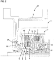
- FIG 2 shows a hybrid module 24 according to a second embodiment.
- the hybrid modules 1, 24 from the figures 1 and 2 are basically constructed in the same way, so that the same reference numbers are used for the same components.
- the hybrid module 24 also has a stator 2 and a rotor 3 which are assigned to an electric machine 4 .
- a double clutch 7 is arranged on the rotor 3 radially and axially inside the rotor 3 and has a first partial clutch 5 and a second partial clutch 6 .
- a separating clutch 8 is arranged on the rotor 3 radially inside the double clutch 7 .
- the hybrid module 24 has three actuating devices 25, 26, 27, which are designed as central slave cylinders.
- the hybrid module 24 from figure 2 can be actuated via a high-pressure system.
- the working pressure is particularly preferably 38 bar.
- the actuating device 25 is integrated in a housing wall section 28 of the hybrid module 24 . Due to the radial and axial nesting of the dual clutch 7 and the separating clutch 8, a particularly compact design of the hybrid module 1, 24 is ensured. It is thus possible to use the hybrid module 1, 24 even in very small vehicles or in vehicles with particularly little installation space and/or an internal combustion engine installed transversely.
Landscapes
- Engineering & Computer Science (AREA)
- Mechanical Engineering (AREA)
- General Engineering & Computer Science (AREA)
- Chemical & Material Sciences (AREA)
- Combustion & Propulsion (AREA)
- Transportation (AREA)
- Hybrid Electric Vehicles (AREA)
- Arrangement Of Transmissions (AREA)
Description
- Die Erfindung betrifft ein Hybridmodul für ein Kraftfahrzeug, umfassend eine einen Stator und einen Rotor aufweisende elektrische Maschine, eine eine erste und zweite Teilkupplung aufweisende Doppelkupplung, die dazu ausgebildet ist, das Hybridmodul trennbar mit einem Getriebe des Kraftfahrzeugs zu koppeln und eine Trennkupplung, die dazu ausgebildet ist, eine Brennkraftmaschine des Kraftfahrzeugs trennbar mit dem Hybridmodul zu koppeln. Dabei sind die Doppelkupplung und die Trennkupplung radial und axial innerhalb des Rotors angeordnet, und die erste und zweite Teilkupplung sind in Axialrichtung hintereinander angeordnet.
- Fahrzeuge mit Hybridantrieb sind hinlänglich bekannt. Diese weisen eine Brennkraftmaschine und eine elektrische Maschine auf, wobei mittels eines Hybridmoduls sichergestellt ist, dass die Brennkraftmaschine mittels der Trennkupplung mit der elektrischen Maschine wirktechnisch gekoppelt werden kann. Ebenso kann die Brennkraftmaschine mit der Trennkupplung von der elektrischen Maschine entkoppelt werden. Ferner weist das Hybridmodul eine Doppelkupplung auf, die dazu dient, ein wirktechnisches Koppeln und Entkoppeln des Hybridantriebs von einem Getriebe des Fahrzeugs zu bewirken. Mit anderen Worten bewirkt die Trennkupplung die Kopplung zwischen elektrischer Maschine und Brennkraftmaschine, wobei die Doppelkupplung anschließend das Hybridmodul mit dem Getriebe koppelt oder von diesem entkoppelt. Bei der gegebenen Anordnung, insbesondere der Anordnung in Form eines P2-Hybridmoduls, stellt die axiale Länge des Hybridmoduls eine kritische Größe dar. Insbesondere in kleineren bzw. Kleinstfahrzeugen ist dabei die Verwendung eines Hybridmoduls nicht oder nur schwierig möglich, da der benötigte Bauraum insbesondere in Axialrichtung nicht oder nur begrenzt zur Verfügung steht.
- Aus der
DE 10 2012 024 699 A1 ist ein Hybridmodul für ein Kraftfahrzeug bekannt, das eine einen Stator und einen Rotor aufweisende elektrische Maschine, eine eine erste und zweite Teilkupplung aufweisende Doppelkupplung, die dazu ausgebildet ist, das Hybridmodul trennbar mit einem Getriebe des Kraftfahrzeugs zu koppeln, und eine Trennkupplung aufweist, die dazu ausgebildet ist, eine Brennkraftmaschine des Kraftfahrzeugs trennbar mit dem Hybridmodul zu koppeln. Die Doppelkupplung ist radial und axial innerhalb des Rotors angeordnet. Die erste und die zweite Teilkupplung sind in Axialrichtung hintereinander angeordnet.
Bezüglich weiteren Standes der Technik wird auf dieUS 2007/0049445 A1 , dieDE 10 2011 117 781 A1 , dieDE 10 2009 059 944 A1 , dieDE 10 2014 014 669 A1 und dieWO 2015/110108 A1 verwiesen.
Der Erfindung liegt daher die Aufgabe zugrunde ein Hybridmodul anzugeben, das weniger Bauraum in Axialrichtung benötigt.
Diese Aufgabe wird mit den in Anspruch 1 angegebenen Maßnahmen gelöst. Weitere vorteilhafte Ausgestaltungen sind Gegenstand der abhängigen Ansprüche.
Zur Lösung dieser Aufgabe ist bei einem Hybridmodul der eingangs genannten Art erfindungsgemäß vorgesehen, dass die Trennkupplung radial und axial innerhalb des Rotors angeordnet ist und in Radialrichtung näher an der Drehachse des Rotors angeordnet ist als die Doppelkupplung.
Erfindungsgemäß wird somit vorgeschlagen, dass sowohl die Trennkupplung, als auch die Doppelkupplung innerhalb des Rotors angeordnet sind. Der Rotor definiert demnach einen Raum, innerhalb dem die Doppelkupplung und die Trennkupplung sowohl radial, als auch axial aufgenommen sind. Die Doppelkupplung ist dabei radial weiter außen am Rotor bzw. im Rotor angeordnet und die Trennkupplung liegt näher an der Drehachse des Rotors als die Doppelkupplung.
Daraus ergibt sich eine besonders kompakte Bauform, da der Rotor, die Doppelkupplung und die Trennkupplung nicht axial hintereinander angeordnet werden müssen, sondern in Radialrichtung geschachtelt angeordnet sind. Durch den Entfall des zusätzlichen axialen Bauraums, kann das Hybridmodul auch in Kleinstfahrzeugen oder in Fahrzeugen mit quer eingebauten Verbrennungsmotor Verwendung finden. Ferner ist vorteilhafter Weise eine einfache Montage möglich, da das Hybridmodul erfindungsgemäß als kompaktes "add-on"-Modul ausgeführt ist, d.h., dass das Hybridmodul über sein Gehäuse am Verbrennungsmotor und/oder am Getriebe befestigt werden kann. - Besonders bevorzugt kann bei dem erfindungsgemäßen Hybridmodul vorgesehen sein, dass die Doppelkupplung und die Trennkupplung jeweils mittels wenigstens einer Innenlamelle oder Außenlamelle mit verschiedenen Wänden des Rotors gekoppelt sind. Mit anderen Worten bilden verschiedene Wände des Rotors den Innenlamellenträger bzw. den Außenlamellenträger der Teilkupplungen der Doppelkupplung bzw. der Trennkupplung aus, so dass die entsprechenden Innenlamellen oder Außenlamellen der Doppelkupplung oder der Trennkupplung an den verschiedenen Wänden des Rotors angeordnet sind. Dadurch ergibt sich eine direkte Integration der Teilkupplungen der Doppelkupplung sowie der Trennkupplung in die Wände des Rotors. Zusätzliche Bauteile, die als Innenlamellenträger oder Außenlamellenträger fungieren, sind somit entbehrlich, was die Bauteileanzahl verringert und die Kompaktheit des Hybridmoduls weiter verbessert.
- Das erfindungsgemäße Hybridmodul kann ferner dahingehend weitergebildet werden, dass die beiden Wände des Rotors, an denen die Doppelkupplung und die Trennkupplung jeweils mittels wenigstens einer Innenlamelle oder Außenlamelle gekoppelt sind, eine Verzahnung aufweisen und einander in Radialrichtung konzentrisch gegenüberliegen. Ersichtlich verlaufen die entsprechenden Wände des Rotors näherungsweise parallel in Axialrichtung und weisen eine Verzahnung auf, die zu der Verzahnung der Innenlamellen bzw. Außenlamellen der Teilkupplungen der Doppelkupplung bzw. der Trennkupplung korrespondiert. Die Teilkupplung ist dabei an einer Wand des Rotors angeordnet, die näher an der Drehachse angeordnet ist, als diejenige Wand des Rotors, an der die Doppelkupplung bzw. die beiden Teilkupplungen der Doppelkupplung angeordnet sind. Die beiden Teilkupplungen der Doppelkupplung sind, wie zuvor beschrieben, in Axialrichtung hintereinander angeordnet. Dadurch ergibt sich ein besonders kompakter Aufbau, da die Doppelkupplung als axiale Doppelkupplung ausgebildet ist und zusammen mit der Trennkupplung innerhalb des Rotors angeordnet ist.
- Gemäß einer weiteren Ausgestaltung des erfindungsgemäßen Hybridmoduls kann vorgesehen sein, dass wenigstens eine Betätigungseinrichtung zum Öffnen und/oder Schließen der Trennkupplung oder der ersten oder der zweiten Teilkupplung zumindest abschnittsweise in eine Gehäusewand des Hybridmoduls integriert ist.
- Üblicherweise wird im Stand der Technik zusätzlicher Bauraum für die Betätigungseinrichtung bzw. die Betätigungseinrichtungen, die den einzelnen Teilkupplungen bzw. der Trennkupplung zugeordnet sind, vorgehalten. Die entsprechenden Betätigungseinrichtungen dienen dem Öffnen und/oder dem Schließen der einzelnen Kupplungen, wobei es unerheblich ist, ob die einzelnen Teilkupplungen bzw. die Trennkupplung als "normally open" oder "normally closed" Kupplungen ausgebildet sind.
- Gemäß dieser Ausgestaltung wird vorgeschlagen, wenigstens eine der Betätigungseinrichtungen in eine Gehäusewand des Hybridmoduls zu integrieren. Das Gehäuse des Hybridmoduls weist dazu bevorzugter Weise in dessen Wand eine Ausnehmung auf, innerhalb der die Betätigungseinrichtung aufgenommen ist. Dadurch reduziert sich der benötigte Bauraum, da die Betätigungseinrichtung zumindest abschnittsweise in der Gehäusewand aufgenommen ist, so dass der benötigte Bauraum sich um diesen Anteil, in dem die Betätigungseinrichtung in der Gehäusewand aufgenommen ist, reduziert.
- Ferner kann bei dem erfindungsgemäßen Hybridmodul vorgesehen sein, dass die der Trennkupplung zugeordnete Betätigungseinrichtung als Zentralausrücker ausgebildet ist. Demnach kann die Betätigungseinrichtung, die zum Öffnen und/oder Schließen der Trennkupplung vorgesehen ist, als Zentralausrücker (CSC, concentric slave cylinder) ausgebildet sein.
- Besonders bevorzugt kann bei dem erfindungsgemäßen Hybridmodul vorgesehen sein, dass die der ersten und/oder die der zweiten Teilkupplung zugeordnete Betätigungseinrichtung als Zentralausrücker ausgebildet ist oder dass die erste und/oder die zweite Teilkupplung mittels einer Dreheinführung betätigbar ist oder dass die der ersten Teilkupplung zugeordnete Betätigungseinrichtung als Zentralausrücker und die zweite Teilkupplung mittels einer Dreheinführung betätigbar ist oder dass die der zweiten Teilkupplung zugeordnete Betätigungseinrichtung als Zentralausrücker und die erste Teilkupplung mittels einer Dreheinführung betätigbar ist.
- Grundsätzlich kann demnach beliebig vorgesehen sein, dass eine der beiden Teilkupplungen der Doppelkupplung oder die Trennkupplung als Zentralausrücker ausgebildet ist oder mittels einer Dreheinführung betätigbar ist. Über die Dreheinführung wird ein Arbeitsfluid, insbesondere ein Öl, in einen entsprechenden Druckraum der Betätigungseinrichtung eingeführt, so dass sich der Druck in dem Druckraum verändert. Durch entsprechendes Fördern des Arbeitsfluids in den oder aus dem Druckraum kann sonach eine Verstellung des dem Druckraum zugeordneten Kolbens bewirkt werden, über dessen Verstellweg ein Öffnen bzw. ein Schließen der entsprechenden Kupplung bewirkt werden kann.
- Gemäß einer weiteren vorteilhaften Ausgestaltung des erfindungsgemäßen Hybridmoduls kann vorgesehen sein, dass wenigstens eine Betätigungseinrichtung einen relativ zu einem Gehäusewandabschnitt beweglichen Kolben aufweist, wobei wenigstens ein Dichtelement an dem Kolben und wenigstens ein Dichtelement an dem Gehäusewandabschnitt angeordnet ist.
- Die beiden Dichtelemente können beispielsweise als O-Ring-Dichtungen ausgebildet sein, wobei eines der beiden Dichtelemente an dem relativ zu dem Gehäusewandabschnitt beweglichen Kolben und das andere Dichtelement in dem Gehäusewandabschnitt angeordnet ist. Der Kolben und der Gehäusewandabschnitt weisen dazu bevorzugt eine Ausnehmung auf, die dazu ausgebildet ist, das entsprechende Dichtelement zumindest abschnittsweise aufzunehmen.
- Besonders bevorzugt ist bei dieser Ausgestaltung vorgesehen, dass das wenigstens eine Dichtelement an dem Kolben und/oder das wenigstens eine Dichtelement an der Gehäusewand vorgespannt sind. Durch die vorgesehene Vorspannung der Dichtelemente im eingebauten Zustand, werden geometrische Toleranzen der Dichtelemente und damit einhergehende Probleme bei der Montage reduziert, wodurch sich die Montage erheblich vereinfacht.
- Das erfindungsgemäße Hybridmodul sieht in einer weiteren Ausgestaltung der Erfindung vor, dass die Trennkupplung und die Doppelkupplung mittels eines Niederdrucksystems oder eines Hochdrucksystems betätigbar sind, wobei bei dem Niederdrucksystem die Trennkupplung mittels eines Zentralausrückers und die Doppelkupplung mittels einer Dreheinführung betätigbar ist und wobei bei dem Hochdrucksystem die Trennkupplung und die Doppelkupplung mittels Zentralausrückern betätigbar sind.
- Demnach ist vorgesehen, dass die Betätigung des Hybridmoduls bzw. der Trennkupplung oder Doppelkupplung zum einen als Niederdrucksystem und zum anderen als Hochdrucksystem ausgeführt sein kann. Das Niederdrucksystem zeichnet sich dadurch aus, dass die Trennkupplung mittels einer als Zentralausrücker ausgebildeten Betätigungseinrichtung betätigbar ist und die beiden Teilkupplungen der Doppelkupplung mittels Dreheinführungen betätigbar sind. Der dazu notwendige Arbeitsdruck, um die einzelnen Betätigungseinrichtungen betreiben zu können, liegt dabei gegenüber dem Hochdrucksystem niedriger.
- Demgegenüber kann die Betätigung des Hybridmoduls bzw. der beiden Teilkupplungen und der Trennkupplung als Hochdrucksystem ausgeführt sein, d.h., dass sämtliche Betätigungseinrichtung als Zentralausrücker ausgebildet sind, wobei der Betriebsdruck im Falle des Hochdrucksystems gegenüber dem Niederdrucksystem höher liegt.
- Besonders bevorzugt kann dabei vorgesehen sein, dass das Niederdrucksystem einen Betriebsdruck von 10 bis 18 bar, besonders bevorzugt 14 bar aufweist, oder dass das Hochdrucksystem einen Betriebsdruck von 30 bis 46 bar aufweist, besonders bevorzugt 38 bar.
- Die Erfindung wird nachfolgend anhand von Ausführungsbeispielen unter Bezugnahme auf die Zeichnungen erläutert. Die Zeichnungen sind schematische Darstellungen und zeigen:
- Figur 1
- ein erfindungsgemäßes Hybridmodul gemäß einem ersten Ausführungsbeispiel; und
- Figur 2
- ein erfindungsgemäßes Hybridmodul gemäß einem zweiten Ausführungsbeispiel.
-
Figur 1 zeigt ein Hybridmodul 1 für ein nicht näher dargestelltes Kraftfahrzeug, umfassend eine einen Stator 2 und einen Rotor 3 aufweisende elektrische Maschine 4, eine eine erste und zweite Teilkupplung 5, 6 aufweisende Doppelkupplung 7, die dazu ausgebildet ist, das Hybridmodul 1 trennbar mit einem Getriebe des Kraftfahrzeugs (nicht dargestellt) zu koppeln und eine Trennkupplung 8, die dazu ausgebildet ist, eine Brennkraftmaschine (nicht dargestellt) des Kraftfahrzeugs trennbar mit dem Hybridmodul 1 zu koppeln. - Ersichtlich ist die Doppelkupplung 7 mit ihren beiden Teilkupplungen 5, 6 und die Trennkupplung 8 sowohl radial als auch axial innerhalb des Rotors 3 angeordnet. Die erste und die zweite Teilkupplung 5, 6 sind in Axialrichtung hintereinander angeordnet, wobei die Doppelkupplung 7 in Radialrichtung weiter von einer Drehachse 9 des Rotors 3 entfernt ist, als die Trennkupplung 8. Mit anderen Worten ist die Trennkupplung 8 in Radialrichtung näher an der Drehachse 9 des Rotors 3 angeordnet als die Doppelkupplung 7.
- Daraus ergibt sich ein besonders kompakter Aufbau, da der für den Rotor 3, die erste und zweite Teilkupplung 5, 6 der Doppelkupplung 7 und die Trennkupplung 8 benötigte Bauraum reduziert wird, da die einzelnen Baugruppen radial bzw. axial ineinander geschachtelt sind. Demnach kann die Doppelkupplung 7 und die Trennkupplung 8 innerhalb des Rotors 3 integriert angeordnet sein.
- Die Trennkupplung 8 ist ersichtlich an einer Wand 10 des Rotors 3 angeordnet, d.h., dass die Wand 10 eine Verzahnung aufweist, an der Innenlamellen 11 der Trennkupplung 8 mittels einer korrespondierenden Verzahnung angeordnet sind. Ebenso sind die erste und die zweite Teilkupplung 5, 6 an einer Wand 12 des Rotors angeordnet, d.h., dass Außenlamellen 13 der Teilkupplungen 5, 6 mittels einer korrespondierenden Verzahnung an der Wand 12 des Rotors 3 angeordnet sind. Demnach sind die Doppelkupplung 7 und die Trennkupplung 8 in die Wände 10, 12 des Rotors 3 integriert. Der Rotor 3 übernimmt mit den Wänden 10, 12 die Funktion des Innenlamellenträgers bzw. des Außenlamellenträger. Die beiden Wände 10, 12 des Rotors 3 sind dabei ersichtlich konzentrisch angeordnet, wobei die Verzahnungen an den Wänden 10, 12 in Radialrichtung einander gegenüberliegen.
- Das Hybridmodul 1 weist eine Betätigungseinrichtung 14 auf, die beispielweise als Zentralausrücker ausgebildet ist. Die Betätigungseinrichtung 14 dient zum Öffnen und/oder Schließen der Trennkupplung 8. Entsprechend weist das Hybridmodul 1 eine Betätigungseinrichtung 15 und eine Betätigungseinrichtung 16 auf, die den Teilkupplungen 5, 6 der Doppelkupplung 7 zugeordnet sind. Die Betätigungseinrichtungen 15, 16 weisen Dreheinführungen auf, mittels derer ein Arbeitsfluid in die entsprechenden Druckräume 17, 18 gefördert werden kann und mittels eines Betätigungselements entgegen der Federkraft eines Rückstellelements eine Betätigungskraft auf die Lamellenpakete der Teilkupplungen 5, 6 bewirkt werden kann.
- Ersichtlich ist die Betätigungseinrichtung 14 zumindest abschnittsweise in eine Gehäusewand 19 des Hybridmoduls 1 integriert. Dadurch erhöht sich die Kompaktheit des Aufbaus weiter.
- Die Betätigungseinrichtung 14 weist ferner zwei Dichtelemente 20, 21 auf, wobei das Dichtelement 20 an einem beweglichen Kolben 22 und das Dichtelement 21 an einem Gehäusewandabschnitt 23 des Gehäuses des Hybridmoduls 1 angeordnet ist. Ersichtlich sind die beiden Dichtelemente in Ausnehmungen im Kolben 22 bzw. im Gehäusewandabschnitt 23 aufgenommen. Die Dichtelemente 20, 21 sind vorgespannt, so dass geometrische Toleranzen der Dichtelemente und damit einhergehende Montageprobleme reduziert werden können.
- Das Hybridmodul 1 von
Figur 1 ist ersichtlich über ein Niederdrucksystem betätigt, da die Betätigungseinrichtung 14 als Zentralausrücker und die Betätigungseinrichtungen 15, 16 mittels einer Dreheinführung betätigbar sind. Der Arbeitsdruck des Arbeitsfluids beträgt bevorzugt 14 bar. -
Figur 2 zeigt ein Hybridmodul 24 gemäß einem zweiten Ausführungsbeispiel. Die Hybridmodule 1, 24 aus denFiguren 1 und2 sind grundsätzlich gleich aufgebaut, so dass gleiche Bezugszeichen für gleiche Bauteile verwendet werden. Insbesondere weist das Hybridmodul 24 ebenfalls einen Stator 2 und einen Rotor 3 auf, die einer elektrischen Maschine 4 zugeordnet sind. Ferner ist an dem Rotor 3 radial und axial innerhalb des Rotors 3 eine Doppelkupplung 7 angeordnet, die eine erste Teilkupplung 5 und eine zweite Teilkupplung 6 aufweist. Radial innerhalb der Doppelkupplung 7 ist eine Trennkupplung 8 an dem Rotor 3 angeordnet. Im Unterschied zu dem Hybridmodul 1 vonFigur 1 weist das Hybridmodul 24 drei Betätigungseinrichtungen 25, 26, 27 auf, die als Zentralausrücker ausgebildet sind. Das Hybridmodul 24 vonFigur 2 ist ersichtlich über ein Hochdrucksystem betätigbar. Der Arbeitsdruck beträgt besonders bevorzugt 38 bar. - Ersichtlich ist die Betätigungseinrichtung 25 in einem Gehäusewandabschnitt 28 des Hybridmoduls 24 integriert. Aufgrund der radialen und axialen Schachtelung der Doppelkupplung 7 und der Trennkupplung 8 ist ein besonders kompakter Aufbau des Hybridmoduls 1, 24 gewährleistet. Es ist somit möglich das Hybridmodul 1, 24 auch bei Kleinstfahrzeugen bzw. bei Fahrzeugen mit besonders wenig Bauraum und/oder quer eingebauter Brennkraftmaschine einzusetzen.
- Selbstverständlich sind die einzelnen Ausführungsbeispiele beliebig miteinander kombinierbar.
-
- 1
- Hybridmodul
- 2
- Stator
- 3
- Rotor
- 4
- elektrische Maschine
- 5
- erste Teilkupplung
- 6
- zweite Teilkupplung
- 7
- Doppelkupplung
- 8
- Trennkupplung
- 9
- Drehachse
- 10
- Wand
- 11
- Innenlamelle
- 12
- Wand
- 13
- Außenlamelle
- 14
- Betätigungseinrichtung
- 15
- Betätigungseinrichtung
- 16
- Betätigungseinrichtung
- 17
- Druckraum
- 18
- Druckraum
- 19
- Gehäusewand
- 20
- Dichtelement
- 21
- Dichtelement
- 22
- Kolben
- 23
- Gehäusewandabschnitt
- 24
- Hybridmodul
- 25
- Betätigungseinrichtung
- 26
- Betätigungseinrichtung
- 27
- Betätigungseinrichtung
- 28
- Gehäusewandabschnitt
Claims (10)
- Hybridmodul (1, 24) für ein Kraftfahrzeug, das aufweist:eine einen Stator (2) und einen Rotor (3) aufweisende elektrische Maschine (4);eine eine erste und zweite Teilkupplung (5, 6) aufweisende Doppelkupplung (7), die dazu ausgebildet ist, das Hybridmodul (1, 24) trennbar mit einem Getriebe des Kraftfahrzeugs zu koppeln; undeine Trennkupplung (8), die dazu ausgebildet ist, eine Brennkraftmaschine des Kraftfahrzeugs trennbar mit dem Hybridmodul (1, 24) zu koppeln,wobeidadurch gekennzeichnet, dass das Hybridmodul über sein Gehäuse an der Brennkraftmaschine und/oder an dem Getriebe befestigt werden kann.die Doppelkupplung (7) und die Trennkupplung (8) radial und axial innerhalb des Rotors (3) angeordnet sind,die erste und die zweite Teilkupplung (5, 6) in Axialrichtung hintereinander angeordnet sind, unddie Trennkupplung (8) in Radialrichtung näher an der Drehachse (9) des Rotors (3) angeordnet ist als die Doppelkupplung (7),
- Hybridmodul nach Anspruch 1, dadurch gekennzeichnet, dass die Doppelkupplung (7) und die Trennkupplung (8) jeweils mittels wenigstens einer Innenlamelle (11) oder Außenlamelle (13) mit verschiedenen Wänden (10, 12) des Rotors (3) gekoppelt sind.
- Hybridmodul nach Anspruch 2, dadurch gekennzeichnet, dass die verschiedenen Wände (10, 12) des Rotors (3) eine Verzahnung aufweisen und einander in Radialrichtung konzentrisch gegenüberliegen.
- Hybridmodul nach einem der vorangehenden Ansprüche, dadurch gekennzeichnet, dass wenigstens eine Betätigungseinrichtung (14 - 16, 25 - 27) zum Öffnen und/oder Schließen der Trennkupplung (8) oder der ersten oder der zweiten Teilkupplung (5, 6) zumindest abschnittsweise in eine Gehäusewand (19) des Hybridmoduls (1, 24) integriert ist.
- Hybridmodul nach Anspruch 4, dadurch gekennzeichnet, dass eine der Trennkupplung (8) zugeordnete Betätigungseinrichtung (14, 25) als Zentralausrücker ausgebildet ist.
- Hybridmodul nach Anspruch 4 oder 5, dadurch gekennzeichnet, dass eine der ersten und/oder eine der zweiten Teilkupplung (5, 6) zugeordnete Betätigungseinrichtung (26, 27) als Zentralausrücker ausgebildet ist oder dass die erste und/oder die zweite Teilkupplung (5, 6) mittels einer Dreheinführung betätigbar ist oder dass die der ersten Teilkupplung (5, 6) zugeordnete Betätigungseinrichtung als Zentralausrücker (26) ausgebildet ist und die zweite Teilkupplung (5, 6) mittels einer Dreheinführung betätigbar ist oder dass die der zweiten Teilkupplung (5, 6) zugeordnete Betätigungseinrichtung (27) als Zentralausrücker ausgebildet ist und die erste Teilkupplung (5, 6) mittels einer Dreheinführung betätigbar ist.
- Hybridmodul nach einem der Ansprüche 4 bis 6, dadurch gekennzeichnet, dass die wenigstens eine Betätigungseinrichtung (14- 16, 25 - 27) einen relativ zu einem Gehäusewandabschnitt (23, 28) beweglichen Kolben (22) aufweist, wobei wenigstens ein Dichtelement (20) an dem Kolben (22) und wenigstens ein Dichtelement (21) an dem Gehäusewandabschnitt (23) angeordnet ist.
- Hybridmodul nach Anspruch 7, dadurch gekennzeichnet, dass das wenigstens eine Dichtelement (20) an dem Kolben (22) und/oder das wenigstens eine Dichtelement (21) an dem Gehäusewandabschnitt (23) vorgespannt sind.
- Hybridmodul nach einem der Ansprüche 4 bis 8, dadurch gekennzeichnet, dass die Trennkupplung (8) und die Doppelkupplung (7) mittels eines Niederdrucksystems oder eines Hochdrucksystems betätigbar ist, wobei bei dem Niederdrucksystem die Trennkupplung (8) mittels eines Zentralausrückers und die Doppelkupplung (7) mittels einer Dreheinführung betätigbar ist und wobei bei dem Hochdrucksystem die Trennkupplung (8) und die Doppelkupplung (7) mittels Zentralausrückern betätigbar sind.
- Hybridmodul nach Anspruch 9, dadurch gekennzeichnet, dass das Niederdrucksystem einen Betriebsdruck von 10 bis 18 bar oder das Hochdrucksystem einen Betriebsdruck von 30 bis 46 bar aufweist.
Applications Claiming Priority (3)
| Application Number | Priority Date | Filing Date | Title |
|---|---|---|---|
| DE102016219425 | 2016-10-06 | ||
| DE102016125072 | 2016-12-21 | ||
| PCT/DE2017/100106 WO2018064998A1 (de) | 2016-10-06 | 2017-02-13 | Hybridmodul |
Publications (3)
| Publication Number | Publication Date |
|---|---|
| EP3322606A1 EP3322606A1 (de) | 2018-05-23 |
| EP3322606B1 EP3322606B1 (de) | 2020-01-29 |
| EP3322606B2 true EP3322606B2 (de) | 2023-01-11 |
Family
ID=58266799
Family Applications (1)
| Application Number | Title | Priority Date | Filing Date |
|---|---|---|---|
| EP17710469.2A Active EP3322606B2 (de) | 2016-10-06 | 2017-02-13 | Hybridmodul |
Country Status (5)
| Country | Link |
|---|---|
| EP (1) | EP3322606B2 (de) |
| KR (1) | KR102274073B1 (de) |
| CN (1) | CN109789764B (de) |
| DE (1) | DE112017005067A5 (de) |
| WO (1) | WO2018064998A1 (de) |
Families Citing this family (13)
| Publication number | Priority date | Publication date | Assignee | Title |
|---|---|---|---|---|
| CN109790880B (zh) * | 2016-11-15 | 2020-12-04 | 基石科技株式会社 | 三重离合器及其致动器 |
| DE102018110038A1 (de) * | 2018-04-26 | 2019-10-31 | Schaeffler Technologies AG & Co. KG | Kupplungsanordnung mit als Blechteil ausgebildeten und mit einem Rotorträger verbundenen Tragbestandteil; sowie Antriebsstrang |
| WO2019211244A1 (fr) * | 2018-05-04 | 2019-11-07 | Valeo Embrayages | Dispositif de transmission pour vehicule automobile |
| FR3080898B1 (fr) * | 2018-05-04 | 2020-12-25 | Valeo Embrayages | Dispositif de transmission pour vehicule automobile |
| DE102018112160A1 (de) * | 2018-05-22 | 2019-11-28 | Schaeffler Technologies AG & Co. KG | Mehrfachkupplungseinrichtung und Hybridmodul für ein Kraftfahrzeug |
| DE102018005522A1 (de) * | 2018-07-12 | 2020-01-16 | Daimler Ag | Hybridgetriebe, insbesondere ein Doppelkupplungs-Hybridgetriebe |
| DE102018132262A1 (de) * | 2018-07-23 | 2020-01-23 | Schaeffler Technologies AG & Co. KG | Hybridmodul mit Eingangswelle mit Drehdurchführung sowie Betätigungseinrichtung für eine von mehreren Kupplungen; sowie Antriebsstrang |
| DE102018129387A1 (de) | 2018-11-22 | 2020-05-28 | Schaeffler Technologies AG & Co. KG | Hybridmodul sowie Antriebsanordnung für ein Kraftfahrzeug |
| DE102018129759A1 (de) | 2018-11-26 | 2020-05-28 | Schaeffler Technologies AG & Co. KG | Hybridmodul |
| DE102018129756A1 (de) | 2018-11-26 | 2020-05-28 | Schaeffler Technologies AG & Co. KG | Hybridmodul |
| DE102019104073A1 (de) * | 2019-02-19 | 2020-08-20 | Schaeffler Technologies AG & Co. KG | Kompakte Kupplungsanordnung einer Dreifachkupplung für ein achsparalleles Hybridmodul |
| DE102019001335A1 (de) * | 2019-02-25 | 2020-08-27 | Daimler Ag | Hybridtriebkopf für ein Kraftfahrzeug sowie Kraftfahrzeug mit einem solchen Hybridtriebkopf |
| US20220227216A1 (en) * | 2019-04-26 | 2022-07-21 | Schaeffler Technologies AG & Co. KG | Modular transmission mechanism for hybrid power system, and hybrid power system |
Citations (5)
| Publication number | Priority date | Publication date | Assignee | Title |
|---|---|---|---|---|
| JP2004306826A (ja) † | 2003-04-08 | 2004-11-04 | Fuji Heavy Ind Ltd | ハイブリッド車両の駆動装置 |
| EP2287487A1 (de) † | 2009-08-21 | 2011-02-23 | Volkswagen Aktiengesellschaft | Antriebsstrangmodul für ein Kraftfahrzeug |
| US20110240384A1 (en) † | 2010-03-30 | 2011-10-06 | Zf Friedrichshafen Ag | Hybrid drive arrangement |
| DE102011117781A1 (de) † | 2011-10-28 | 2013-05-02 | Getrag Getriebe- Und Zahnradfabrik Hermann Hagenmeyer Gmbh & Cie Kg | Kupplungsanordnung und Hybrid-Doppelkupplungsgetriebe |
| WO2017028856A1 (de) † | 2015-08-20 | 2017-02-23 | Schaeffler Technologies AG & Co. KG | Kupplungseinrichtung für hybridantrieb |
Family Cites Families (23)
| Publication number | Priority date | Publication date | Assignee | Title |
|---|---|---|---|---|
| DE102005040771A1 (de) * | 2005-08-29 | 2007-03-08 | Zf Friedrichshafen Ag | Antriebsstrang eines Hybridfahrzeuges |
| EP1777426B1 (de) * | 2005-10-20 | 2008-10-08 | Getrag Ford Transmissions GmbH | Doppelkupplung |
| DE102006040638A1 (de) * | 2006-08-30 | 2008-03-13 | Robert Bosch Gmbh | Verfahren zum Betreiben eines Hybridantriebs |
| DE102006058947A1 (de) * | 2006-12-14 | 2008-06-19 | Dr.Ing.H.C. F. Porsche Ag | Doppelkupplung für einen Hybrid-Antrieb |
| JP5076829B2 (ja) * | 2007-11-20 | 2012-11-21 | アイシン精機株式会社 | ハイブリッド車両 |
| DE102009059944A1 (de) * | 2009-01-19 | 2010-07-22 | Luk Lamellen Und Kupplungsbau Beteiligungs Kg | Hybridmodul für einen Antriebsstrang eines Fahrzeuges |
| JP5198348B2 (ja) * | 2009-01-30 | 2013-05-15 | 本田技研工業株式会社 | ハイブリッド車両用トランスミッション |
| FR2941893B1 (fr) * | 2009-02-06 | 2011-02-11 | Peugeot Citroen Automobiles Sa | Dispositif de commande rapprochee d'au moins un embrayage faisant partie d'un groupe motopropulseur hybride a machine electrique tournante d'un vehicule. |
| DE102009028514A1 (de) * | 2009-08-13 | 2011-02-17 | Zf Friedrichshafen Ag | Kraftfahrzeuggetriebe |
| CN102114766B (zh) * | 2009-12-31 | 2014-03-19 | 比亚迪股份有限公司 | 一种混合动力驱动系统及其驱动方法 |
| CN102259583B (zh) * | 2010-05-31 | 2014-03-19 | 比亚迪股份有限公司 | 混合动力驱动系统及具有该系统的车辆 |
| DE102011081909A1 (de) * | 2010-10-06 | 2012-04-12 | Schaeffler Technologies Gmbh & Co. Kg | Doppelkupplung |
| DE102011100256A1 (de) * | 2011-04-27 | 2012-10-31 | Getrag Getriebe- Und Zahnradfabrik Hermann Hagenmeyer Gmbh & Cie Kg | Hybrid-Antriebsstrang für ein Kraftfahrzeug |
| CN202399886U (zh) * | 2011-12-19 | 2012-08-29 | 同济大学 | 模块化的混合动力车用干式双圆盘式离合器电机总成 |
| DE102012024699A1 (de) * | 2012-01-13 | 2013-07-18 | Borgwarner Inc. | Kupplungsanordnung mit einer Doppelkupplungseinrichtung |
| DE102014203785A1 (de) * | 2013-03-07 | 2014-09-11 | Schaeffler Technologies Gmbh & Co. Kg | Übertragungseinrichtung und Hybridmodul |
| DE102013006858B4 (de) * | 2013-04-22 | 2023-10-05 | Volkswagen Aktiengesellschaft | Hybridantriebsstrangvorrichtung für ein Kraftfahrzeug |
| DE102013013947B4 (de) * | 2013-08-21 | 2015-05-13 | Audi Ag | Hybridantriebsvorrichtung für ein Kraftfahrzeug |
| JP2015042532A (ja) * | 2013-08-26 | 2015-03-05 | アイシン・エィ・ダブリュ株式会社 | 車両用駆動装置 |
| US10556498B2 (en) * | 2014-01-21 | 2020-02-11 | Schaeffler Technologies AG & Co. KG | CVT drive train |
| DE102014014236A1 (de) * | 2014-02-22 | 2015-08-27 | Borgwarner Inc. | Antriebsstrang für ein Kraftfahrzeug und Verfahren zum Betrieb eines solchen Antriebsstrangs |
| DE102014014669A1 (de) * | 2014-10-02 | 2016-04-07 | Borgwarner Inc. | Drehmomentübertragungsvorrichtung und Antriebsstrang mit einer solchen Drehmomentübertragungsvorrichtung für ein Kraftfahrzeug |
| DE102014019431B4 (de) * | 2014-12-22 | 2023-01-12 | Audi Ag | Hybridantrieb für ein Fahrzeug |
-
2017
- 2017-02-13 EP EP17710469.2A patent/EP3322606B2/de active Active
- 2017-02-13 WO PCT/DE2017/100106 patent/WO2018064998A1/de not_active Ceased
- 2017-02-13 DE DE112017005067.7T patent/DE112017005067A5/de not_active Withdrawn
- 2017-02-13 CN CN201780061000.4A patent/CN109789764B/zh active Active
- 2017-02-13 KR KR1020197009429A patent/KR102274073B1/ko active Active
Patent Citations (5)
| Publication number | Priority date | Publication date | Assignee | Title |
|---|---|---|---|---|
| JP2004306826A (ja) † | 2003-04-08 | 2004-11-04 | Fuji Heavy Ind Ltd | ハイブリッド車両の駆動装置 |
| EP2287487A1 (de) † | 2009-08-21 | 2011-02-23 | Volkswagen Aktiengesellschaft | Antriebsstrangmodul für ein Kraftfahrzeug |
| US20110240384A1 (en) † | 2010-03-30 | 2011-10-06 | Zf Friedrichshafen Ag | Hybrid drive arrangement |
| DE102011117781A1 (de) † | 2011-10-28 | 2013-05-02 | Getrag Getriebe- Und Zahnradfabrik Hermann Hagenmeyer Gmbh & Cie Kg | Kupplungsanordnung und Hybrid-Doppelkupplungsgetriebe |
| WO2017028856A1 (de) † | 2015-08-20 | 2017-02-23 | Schaeffler Technologies AG & Co. KG | Kupplungseinrichtung für hybridantrieb |
Also Published As
| Publication number | Publication date |
|---|---|
| CN109789764B (zh) | 2022-04-01 |
| KR102274073B1 (ko) | 2021-07-08 |
| DE112017005067A5 (de) | 2019-07-18 |
| WO2018064998A1 (de) | 2018-04-12 |
| KR20190058506A (ko) | 2019-05-29 |
| EP3322606B1 (de) | 2020-01-29 |
| CN109789764A (zh) | 2019-05-21 |
| EP3322606A1 (de) | 2018-05-23 |
Similar Documents
| Publication | Publication Date | Title |
|---|---|---|
| EP3322606B2 (de) | Hybridmodul | |
| DE102009038344B4 (de) | Antriebsstrangmodul für ein Kraftfahrzeug | |
| EP3337998B1 (de) | Kupplungseinrichtung für hybridantrieb | |
| EP2795150B1 (de) | Doppelkupplung | |
| WO2018095474A1 (de) | Kupplungseinrichtung | |
| DE102011117781A1 (de) | Kupplungsanordnung und Hybrid-Doppelkupplungsgetriebe | |
| DE102015215895A1 (de) | Kupplungseinrichtung für Hybridantrieb | |
| DE102015215876A1 (de) | Kupplungseinrichtung für Hybridantrieb | |
| WO2015018575A1 (de) | Kühlung für eine hybridantriebsanordnung | |
| EP3140899B1 (de) | Baueinheit für ein kraftfahrzeug mit einer elektrische maschine und einer kupplungsbetätigungseinrichtung | |
| DE102017130478A1 (de) | Einschubmodul, Hybridmodul, Antriebsstrang für ein Kraftfahrzeug und Verfahren zum Zusammenbauen eines Antriebsstrangs | |
| DE102011107696A1 (de) | Ausrückereinheit für eine Doppelkupplung | |
| DE102012220892A1 (de) | Nasskupplung | |
| DE102015204385A1 (de) | Axialkolbenmaschine | |
| DE102008054758A1 (de) | Förderaggregat | |
| DE102018130334A1 (de) | Kupplungseinrichtung | |
| DE102015213873A1 (de) | Axiale Lamellenkupplung | |
| EP3883802B1 (de) | Hybridmodul sowie antriebsanordnung für ein kraftfahrzeug | |
| EP3759371B1 (de) | Kupplungsanordnung sowie diese kupplungsanordnung aufweisende antriebseinheit | |
| DE102018132265A1 (de) | Hybridmodul und Antriebsstrang | |
| EP3826873B1 (de) | Hybridmodul mit eingangswelle mit drehdurchführung sowie betätigungseinrichtung für eine von mehreren kupplungen; sowie antriebsstrang | |
| DE102016206967A1 (de) | Getriebe für ein Kraftfahrzeug | |
| DE102018205474A1 (de) | Ölführung in einem Hybridmodul | |
| WO2020094465A1 (de) | Doppelkupplungsanordnung für einen kraftfahrzeugantriebsstrang | |
| DE102016125064A1 (de) | Hybridmodul und zugehöriges Herstellungsverfahren |
Legal Events
| Date | Code | Title | Description |
|---|---|---|---|
| STAA | Information on the status of an ep patent application or granted ep patent |
Free format text: STATUS: UNKNOWN |
|
| STAA | Information on the status of an ep patent application or granted ep patent |
Free format text: STATUS: THE INTERNATIONAL PUBLICATION HAS BEEN MADE |
|
| PUAI | Public reference made under article 153(3) epc to a published international application that has entered the european phase |
Free format text: ORIGINAL CODE: 0009012 |
|
| STAA | Information on the status of an ep patent application or granted ep patent |
Free format text: STATUS: REQUEST FOR EXAMINATION WAS MADE |
|
| 17P | Request for examination filed |
Effective date: 20170705 |
|
| AK | Designated contracting states |
Kind code of ref document: A1 Designated state(s): AL AT BE BG CH CY CZ DE DK EE ES FI FR GB GR HR HU IE IS IT LI LT LU LV MC MK MT NL NO PL PT RO RS SE SI SK SM TR |
|
| AX | Request for extension of the european patent |
Extension state: BA ME |
|
| RIC1 | Information provided on ipc code assigned before grant |
Ipc: B60K 6/48 20071001AFI20171212BHEP Ipc: B60K 6/38 20071001ALI20171212BHEP Ipc: F16D 21/06 20060101ALI20171212BHEP Ipc: B60K 6/40 20071001ALI20171212BHEP |
|
| GRAP | Despatch of communication of intention to grant a patent |
Free format text: ORIGINAL CODE: EPIDOSNIGR1 |
|
| STAA | Information on the status of an ep patent application or granted ep patent |
Free format text: STATUS: GRANT OF PATENT IS INTENDED |
|
| DAV | Request for validation of the european patent (deleted) | ||
| DAX | Request for extension of the european patent (deleted) | ||
| INTG | Intention to grant announced |
Effective date: 20190402 |
|
| GRAS | Grant fee paid |
Free format text: ORIGINAL CODE: EPIDOSNIGR3 |
|
| GRAA | (expected) grant |
Free format text: ORIGINAL CODE: 0009210 |
|
| STAA | Information on the status of an ep patent application or granted ep patent |
Free format text: STATUS: THE PATENT HAS BEEN GRANTED |
|
| AK | Designated contracting states |
Kind code of ref document: B1 Designated state(s): AL AT BE BG CH CY CZ DE DK EE ES FI FR GB GR HR HU IE IS IT LI LT LU LV MC MK MT NL NO PL PT RO RS SE SI SK SM TR |
|
| REG | Reference to a national code |
Ref country code: GB Ref legal event code: FG4D Free format text: NOT ENGLISH |
|
| REG | Reference to a national code |
Ref country code: CH Ref legal event code: EP |
|
| REG | Reference to a national code |
Ref country code: AT Ref legal event code: REF Ref document number: 1228258 Country of ref document: AT Kind code of ref document: T Effective date: 20200215 |
|
| REG | Reference to a national code |
Ref country code: IE Ref legal event code: FG4D Free format text: LANGUAGE OF EP DOCUMENT: GERMAN |
|
| REG | Reference to a national code |
Ref country code: DE Ref legal event code: R096 Ref document number: 502017003637 Country of ref document: DE |
|
| REG | Reference to a national code |
Ref country code: NL Ref legal event code: MP Effective date: 20200129 |
|
| PG25 | Lapsed in a contracting state [announced via postgrant information from national office to epo] |
Ref country code: RS Free format text: LAPSE BECAUSE OF FAILURE TO SUBMIT A TRANSLATION OF THE DESCRIPTION OR TO PAY THE FEE WITHIN THE PRESCRIBED TIME-LIMIT Effective date: 20200129 Ref country code: FI Free format text: LAPSE BECAUSE OF FAILURE TO SUBMIT A TRANSLATION OF THE DESCRIPTION OR TO PAY THE FEE WITHIN THE PRESCRIBED TIME-LIMIT Effective date: 20200129 Ref country code: PT Free format text: LAPSE BECAUSE OF FAILURE TO SUBMIT A TRANSLATION OF THE DESCRIPTION OR TO PAY THE FEE WITHIN THE PRESCRIBED TIME-LIMIT Effective date: 20200621 Ref country code: NO Free format text: LAPSE BECAUSE OF FAILURE TO SUBMIT A TRANSLATION OF THE DESCRIPTION OR TO PAY THE FEE WITHIN THE PRESCRIBED TIME-LIMIT Effective date: 20200429 |
|
| REG | Reference to a national code |
Ref country code: LT Ref legal event code: MG4D |
|
| PG25 | Lapsed in a contracting state [announced via postgrant information from national office to epo] |
Ref country code: GR Free format text: LAPSE BECAUSE OF FAILURE TO SUBMIT A TRANSLATION OF THE DESCRIPTION OR TO PAY THE FEE WITHIN THE PRESCRIBED TIME-LIMIT Effective date: 20200430 Ref country code: BG Free format text: LAPSE BECAUSE OF FAILURE TO SUBMIT A TRANSLATION OF THE DESCRIPTION OR TO PAY THE FEE WITHIN THE PRESCRIBED TIME-LIMIT Effective date: 20200429 Ref country code: HR Free format text: LAPSE BECAUSE OF FAILURE TO SUBMIT A TRANSLATION OF THE DESCRIPTION OR TO PAY THE FEE WITHIN THE PRESCRIBED TIME-LIMIT Effective date: 20200129 Ref country code: IS Free format text: LAPSE BECAUSE OF FAILURE TO SUBMIT A TRANSLATION OF THE DESCRIPTION OR TO PAY THE FEE WITHIN THE PRESCRIBED TIME-LIMIT Effective date: 20200529 Ref country code: SE Free format text: LAPSE BECAUSE OF FAILURE TO SUBMIT A TRANSLATION OF THE DESCRIPTION OR TO PAY THE FEE WITHIN THE PRESCRIBED TIME-LIMIT Effective date: 20200129 Ref country code: LV Free format text: LAPSE BECAUSE OF FAILURE TO SUBMIT A TRANSLATION OF THE DESCRIPTION OR TO PAY THE FEE WITHIN THE PRESCRIBED TIME-LIMIT Effective date: 20200129 |
|
| PG25 | Lapsed in a contracting state [announced via postgrant information from national office to epo] |
Ref country code: NL Free format text: LAPSE BECAUSE OF FAILURE TO SUBMIT A TRANSLATION OF THE DESCRIPTION OR TO PAY THE FEE WITHIN THE PRESCRIBED TIME-LIMIT Effective date: 20200129 |
|
| REG | Reference to a national code |
Ref country code: CH Ref legal event code: PL |
|
| REG | Reference to a national code |
Ref country code: DE Ref legal event code: R026 Ref document number: 502017003637 Country of ref document: DE Ref country code: BE Ref legal event code: MM Effective date: 20200229 |
|
| PG25 | Lapsed in a contracting state [announced via postgrant information from national office to epo] |
Ref country code: SM Free format text: LAPSE BECAUSE OF FAILURE TO SUBMIT A TRANSLATION OF THE DESCRIPTION OR TO PAY THE FEE WITHIN THE PRESCRIBED TIME-LIMIT Effective date: 20200129 Ref country code: EE Free format text: LAPSE BECAUSE OF FAILURE TO SUBMIT A TRANSLATION OF THE DESCRIPTION OR TO PAY THE FEE WITHIN THE PRESCRIBED TIME-LIMIT Effective date: 20200129 Ref country code: SK Free format text: LAPSE BECAUSE OF FAILURE TO SUBMIT A TRANSLATION OF THE DESCRIPTION OR TO PAY THE FEE WITHIN THE PRESCRIBED TIME-LIMIT Effective date: 20200129 Ref country code: DK Free format text: LAPSE BECAUSE OF FAILURE TO SUBMIT A TRANSLATION OF THE DESCRIPTION OR TO PAY THE FEE WITHIN THE PRESCRIBED TIME-LIMIT Effective date: 20200129 Ref country code: MC Free format text: LAPSE BECAUSE OF FAILURE TO SUBMIT A TRANSLATION OF THE DESCRIPTION OR TO PAY THE FEE WITHIN THE PRESCRIBED TIME-LIMIT Effective date: 20200129 Ref country code: CZ Free format text: LAPSE BECAUSE OF FAILURE TO SUBMIT A TRANSLATION OF THE DESCRIPTION OR TO PAY THE FEE WITHIN THE PRESCRIBED TIME-LIMIT Effective date: 20200129 Ref country code: RO Free format text: LAPSE BECAUSE OF FAILURE TO SUBMIT A TRANSLATION OF THE DESCRIPTION OR TO PAY THE FEE WITHIN THE PRESCRIBED TIME-LIMIT Effective date: 20200129 Ref country code: LU Free format text: LAPSE BECAUSE OF NON-PAYMENT OF DUE FEES Effective date: 20200213 Ref country code: LT Free format text: LAPSE BECAUSE OF FAILURE TO SUBMIT A TRANSLATION OF THE DESCRIPTION OR TO PAY THE FEE WITHIN THE PRESCRIBED TIME-LIMIT Effective date: 20200129 Ref country code: ES Free format text: LAPSE BECAUSE OF FAILURE TO SUBMIT A TRANSLATION OF THE DESCRIPTION OR TO PAY THE FEE WITHIN THE PRESCRIBED TIME-LIMIT Effective date: 20200129 |
|
| PLBI | Opposition filed |
Free format text: ORIGINAL CODE: 0009260 |
|
| PLAB | Opposition data, opponent's data or that of the opponent's representative modified |
Free format text: ORIGINAL CODE: 0009299OPPO |
|
| PLAX | Notice of opposition and request to file observation + time limit sent |
Free format text: ORIGINAL CODE: EPIDOSNOBS2 |
|
| PG25 | Lapsed in a contracting state [announced via postgrant information from national office to epo] |
Ref country code: LI Free format text: LAPSE BECAUSE OF NON-PAYMENT OF DUE FEES Effective date: 20200229 Ref country code: CH Free format text: LAPSE BECAUSE OF NON-PAYMENT OF DUE FEES Effective date: 20200229 |
|
| 26 | Opposition filed |
Opponent name: VALEO EMBRAYAGES Effective date: 20201028 |
|
| R26 | Opposition filed (corrected) |
Opponent name: VALEO EMBRAYAGES Effective date: 20201028 |
|
| PG25 | Lapsed in a contracting state [announced via postgrant information from national office to epo] |
Ref country code: IT Free format text: LAPSE BECAUSE OF FAILURE TO SUBMIT A TRANSLATION OF THE DESCRIPTION OR TO PAY THE FEE WITHIN THE PRESCRIBED TIME-LIMIT Effective date: 20200129 Ref country code: IE Free format text: LAPSE BECAUSE OF NON-PAYMENT OF DUE FEES Effective date: 20200213 |
|
| PG25 | Lapsed in a contracting state [announced via postgrant information from national office to epo] |
Ref country code: SI Free format text: LAPSE BECAUSE OF FAILURE TO SUBMIT A TRANSLATION OF THE DESCRIPTION OR TO PAY THE FEE WITHIN THE PRESCRIBED TIME-LIMIT Effective date: 20200129 Ref country code: BE Free format text: LAPSE BECAUSE OF NON-PAYMENT OF DUE FEES Effective date: 20200229 Ref country code: PL Free format text: LAPSE BECAUSE OF FAILURE TO SUBMIT A TRANSLATION OF THE DESCRIPTION OR TO PAY THE FEE WITHIN THE PRESCRIBED TIME-LIMIT Effective date: 20200129 |
|
| PLAF | Information modified related to communication of a notice of opposition and request to file observations + time limit |
Free format text: ORIGINAL CODE: EPIDOSCOBS2 |
|
| PLBB | Reply of patent proprietor to notice(s) of opposition received |
Free format text: ORIGINAL CODE: EPIDOSNOBS3 |
|
| PLAB | Opposition data, opponent's data or that of the opponent's representative modified |
Free format text: ORIGINAL CODE: 0009299OPPO |
|
| R26 | Opposition filed (corrected) |
Opponent name: VALEO EMBRAYAGES Effective date: 20201028 |
|
| GBPC | Gb: european patent ceased through non-payment of renewal fee |
Effective date: 20210213 |
|
| PG25 | Lapsed in a contracting state [announced via postgrant information from national office to epo] |
Ref country code: GB Free format text: LAPSE BECAUSE OF NON-PAYMENT OF DUE FEES Effective date: 20210213 |
|
| PG25 | Lapsed in a contracting state [announced via postgrant information from national office to epo] |
Ref country code: TR Free format text: LAPSE BECAUSE OF FAILURE TO SUBMIT A TRANSLATION OF THE DESCRIPTION OR TO PAY THE FEE WITHIN THE PRESCRIBED TIME-LIMIT Effective date: 20200129 Ref country code: MT Free format text: LAPSE BECAUSE OF FAILURE TO SUBMIT A TRANSLATION OF THE DESCRIPTION OR TO PAY THE FEE WITHIN THE PRESCRIBED TIME-LIMIT Effective date: 20200129 Ref country code: CY Free format text: LAPSE BECAUSE OF FAILURE TO SUBMIT A TRANSLATION OF THE DESCRIPTION OR TO PAY THE FEE WITHIN THE PRESCRIBED TIME-LIMIT Effective date: 20200129 |
|
| PG25 | Lapsed in a contracting state [announced via postgrant information from national office to epo] |
Ref country code: MK Free format text: LAPSE BECAUSE OF FAILURE TO SUBMIT A TRANSLATION OF THE DESCRIPTION OR TO PAY THE FEE WITHIN THE PRESCRIBED TIME-LIMIT Effective date: 20200129 Ref country code: AL Free format text: LAPSE BECAUSE OF FAILURE TO SUBMIT A TRANSLATION OF THE DESCRIPTION OR TO PAY THE FEE WITHIN THE PRESCRIBED TIME-LIMIT Effective date: 20200129 |
|
| PUAH | Patent maintained in amended form |
Free format text: ORIGINAL CODE: 0009272 |
|
| STAA | Information on the status of an ep patent application or granted ep patent |
Free format text: STATUS: PATENT MAINTAINED AS AMENDED |
|
| 27A | Patent maintained in amended form |
Effective date: 20230111 |
|
| AK | Designated contracting states |
Kind code of ref document: B2 Designated state(s): AL AT BE BG CH CY CZ DE DK EE ES FI FR GB GR HR HU IE IS IT LI LT LU LV MC MK MT NL NO PL PT RO RS SE SI SK SM TR |
|
| REG | Reference to a national code |
Ref country code: DE Ref legal event code: R102 Ref document number: 502017003637 Country of ref document: DE |
|
| REG | Reference to a national code |
Ref country code: AT Ref legal event code: MM01 Ref document number: 1228258 Country of ref document: AT Kind code of ref document: T Effective date: 20220213 |
|
| PG25 | Lapsed in a contracting state [announced via postgrant information from national office to epo] |
Ref country code: AT Free format text: LAPSE BECAUSE OF NON-PAYMENT OF DUE FEES Effective date: 20220213 |
|
| P01 | Opt-out of the competence of the unified patent court (upc) registered |
Effective date: 20230522 |
|
| PGFP | Annual fee paid to national office [announced via postgrant information from national office to epo] |
Ref country code: FR Payment date: 20250221 Year of fee payment: 9 |
|
| PGFP | Annual fee paid to national office [announced via postgrant information from national office to epo] |
Ref country code: DE Payment date: 20250422 Year of fee payment: 9 |