EP3319098A1 - Intravascular blood pump comprising corrosion resistant permanent magnet - Google Patents
Intravascular blood pump comprising corrosion resistant permanent magnet Download PDFInfo
- Publication number
- EP3319098A1 EP3319098A1 EP16196804.5A EP16196804A EP3319098A1 EP 3319098 A1 EP3319098 A1 EP 3319098A1 EP 16196804 A EP16196804 A EP 16196804A EP 3319098 A1 EP3319098 A1 EP 3319098A1
- Authority
- EP
- European Patent Office
- Prior art keywords
- magnet
- layer
- metal
- linker
- magnet body
- Prior art date
- Legal status (The legal status is an assumption and is not a legal conclusion. Google has not performed a legal analysis and makes no representation as to the accuracy of the status listed.)
- Withdrawn
Links
Images

Classifications
-
- H—ELECTRICITY
- H01—ELECTRIC ELEMENTS
- H01F—MAGNETS; INDUCTANCES; TRANSFORMERS; SELECTION OF MATERIALS FOR THEIR MAGNETIC PROPERTIES
- H01F41/00—Apparatus or processes specially adapted for manufacturing or assembling magnets, inductances or transformers; Apparatus or processes specially adapted for manufacturing materials characterised by their magnetic properties
- H01F41/02—Apparatus or processes specially adapted for manufacturing or assembling magnets, inductances or transformers; Apparatus or processes specially adapted for manufacturing materials characterised by their magnetic properties for manufacturing cores, coils, or magnets
- H01F41/0253—Apparatus or processes specially adapted for manufacturing or assembling magnets, inductances or transformers; Apparatus or processes specially adapted for manufacturing materials characterised by their magnetic properties for manufacturing cores, coils, or magnets for manufacturing permanent magnets
- H01F41/026—Apparatus or processes specially adapted for manufacturing or assembling magnets, inductances or transformers; Apparatus or processes specially adapted for manufacturing materials characterised by their magnetic properties for manufacturing cores, coils, or magnets for manufacturing permanent magnets protecting methods against environmental influences, e.g. oxygen, by surface treatment
-
- A—HUMAN NECESSITIES
- A61—MEDICAL OR VETERINARY SCIENCE; HYGIENE
- A61M—DEVICES FOR INTRODUCING MEDIA INTO, OR ONTO, THE BODY; DEVICES FOR TRANSDUCING BODY MEDIA OR FOR TAKING MEDIA FROM THE BODY; DEVICES FOR PRODUCING OR ENDING SLEEP OR STUPOR
- A61M60/00—Blood pumps; Devices for mechanical circulatory actuation; Balloon pumps for circulatory assistance
- A61M60/10—Location thereof with respect to the patient's body
- A61M60/122—Implantable pumps or pumping devices, i.e. the blood being pumped inside the patient's body
- A61M60/126—Implantable pumps or pumping devices, i.e. the blood being pumped inside the patient's body implantable via, into, inside, in line, branching on, or around a blood vessel
- A61M60/13—Implantable pumps or pumping devices, i.e. the blood being pumped inside the patient's body implantable via, into, inside, in line, branching on, or around a blood vessel by means of a catheter allowing explantation, e.g. catheter pumps temporarily introduced via the vascular system
-
- A—HUMAN NECESSITIES
- A61—MEDICAL OR VETERINARY SCIENCE; HYGIENE
- A61M—DEVICES FOR INTRODUCING MEDIA INTO, OR ONTO, THE BODY; DEVICES FOR TRANSDUCING BODY MEDIA OR FOR TAKING MEDIA FROM THE BODY; DEVICES FOR PRODUCING OR ENDING SLEEP OR STUPOR
- A61M60/00—Blood pumps; Devices for mechanical circulatory actuation; Balloon pumps for circulatory assistance
- A61M60/10—Location thereof with respect to the patient's body
- A61M60/122—Implantable pumps or pumping devices, i.e. the blood being pumped inside the patient's body
- A61M60/126—Implantable pumps or pumping devices, i.e. the blood being pumped inside the patient's body implantable via, into, inside, in line, branching on, or around a blood vessel
- A61M60/135—Implantable pumps or pumping devices, i.e. the blood being pumped inside the patient's body implantable via, into, inside, in line, branching on, or around a blood vessel inside a blood vessel, e.g. using grafting
-
- A—HUMAN NECESSITIES
- A61—MEDICAL OR VETERINARY SCIENCE; HYGIENE
- A61M—DEVICES FOR INTRODUCING MEDIA INTO, OR ONTO, THE BODY; DEVICES FOR TRANSDUCING BODY MEDIA OR FOR TAKING MEDIA FROM THE BODY; DEVICES FOR PRODUCING OR ENDING SLEEP OR STUPOR
- A61M60/00—Blood pumps; Devices for mechanical circulatory actuation; Balloon pumps for circulatory assistance
- A61M60/20—Type thereof
- A61M60/205—Non-positive displacement blood pumps
- A61M60/216—Non-positive displacement blood pumps including a rotating member acting on the blood, e.g. impeller
-
- A—HUMAN NECESSITIES
- A61—MEDICAL OR VETERINARY SCIENCE; HYGIENE
- A61M—DEVICES FOR INTRODUCING MEDIA INTO, OR ONTO, THE BODY; DEVICES FOR TRANSDUCING BODY MEDIA OR FOR TAKING MEDIA FROM THE BODY; DEVICES FOR PRODUCING OR ENDING SLEEP OR STUPOR
- A61M60/00—Blood pumps; Devices for mechanical circulatory actuation; Balloon pumps for circulatory assistance
- A61M60/40—Details relating to driving
- A61M60/403—Details relating to driving for non-positive displacement blood pumps
- A61M60/408—Details relating to driving for non-positive displacement blood pumps the force acting on the blood contacting member being mechanical, e.g. transmitted by a shaft or cable
- A61M60/411—Details relating to driving for non-positive displacement blood pumps the force acting on the blood contacting member being mechanical, e.g. transmitted by a shaft or cable generated by an electromotor
- A61M60/416—Details relating to driving for non-positive displacement blood pumps the force acting on the blood contacting member being mechanical, e.g. transmitted by a shaft or cable generated by an electromotor transmitted directly by the motor rotor drive shaft
-
- A—HUMAN NECESSITIES
- A61—MEDICAL OR VETERINARY SCIENCE; HYGIENE
- A61M—DEVICES FOR INTRODUCING MEDIA INTO, OR ONTO, THE BODY; DEVICES FOR TRANSDUCING BODY MEDIA OR FOR TAKING MEDIA FROM THE BODY; DEVICES FOR PRODUCING OR ENDING SLEEP OR STUPOR
- A61M60/00—Blood pumps; Devices for mechanical circulatory actuation; Balloon pumps for circulatory assistance
- A61M60/40—Details relating to driving
- A61M60/403—Details relating to driving for non-positive displacement blood pumps
- A61M60/419—Details relating to driving for non-positive displacement blood pumps the force acting on the blood contacting member being permanent magnetic, e.g. from a rotating magnetic coupling between driving and driven magnets
-
- A—HUMAN NECESSITIES
- A61—MEDICAL OR VETERINARY SCIENCE; HYGIENE
- A61M—DEVICES FOR INTRODUCING MEDIA INTO, OR ONTO, THE BODY; DEVICES FOR TRANSDUCING BODY MEDIA OR FOR TAKING MEDIA FROM THE BODY; DEVICES FOR PRODUCING OR ENDING SLEEP OR STUPOR
- A61M60/00—Blood pumps; Devices for mechanical circulatory actuation; Balloon pumps for circulatory assistance
- A61M60/40—Details relating to driving
- A61M60/403—Details relating to driving for non-positive displacement blood pumps
- A61M60/422—Details relating to driving for non-positive displacement blood pumps the force acting on the blood contacting member being electromagnetic, e.g. using canned motor pumps
-
- A—HUMAN NECESSITIES
- A61—MEDICAL OR VETERINARY SCIENCE; HYGIENE
- A61M—DEVICES FOR INTRODUCING MEDIA INTO, OR ONTO, THE BODY; DEVICES FOR TRANSDUCING BODY MEDIA OR FOR TAKING MEDIA FROM THE BODY; DEVICES FOR PRODUCING OR ENDING SLEEP OR STUPOR
- A61M60/00—Blood pumps; Devices for mechanical circulatory actuation; Balloon pumps for circulatory assistance
- A61M60/80—Constructional details other than related to driving
- A61M60/802—Constructional details other than related to driving of non-positive displacement blood pumps
- A61M60/818—Bearings
- A61M60/82—Magnetic bearings
-
- A—HUMAN NECESSITIES
- A61—MEDICAL OR VETERINARY SCIENCE; HYGIENE
- A61M—DEVICES FOR INTRODUCING MEDIA INTO, OR ONTO, THE BODY; DEVICES FOR TRANSDUCING BODY MEDIA OR FOR TAKING MEDIA FROM THE BODY; DEVICES FOR PRODUCING OR ENDING SLEEP OR STUPOR
- A61M60/00—Blood pumps; Devices for mechanical circulatory actuation; Balloon pumps for circulatory assistance
- A61M60/80—Constructional details other than related to driving
- A61M60/802—Constructional details other than related to driving of non-positive displacement blood pumps
- A61M60/818—Bearings
- A61M60/825—Contact bearings, e.g. ball-and-cup or pivot bearings
-
- A—HUMAN NECESSITIES
- A61—MEDICAL OR VETERINARY SCIENCE; HYGIENE
- A61M—DEVICES FOR INTRODUCING MEDIA INTO, OR ONTO, THE BODY; DEVICES FOR TRANSDUCING BODY MEDIA OR FOR TAKING MEDIA FROM THE BODY; DEVICES FOR PRODUCING OR ENDING SLEEP OR STUPOR
- A61M60/00—Blood pumps; Devices for mechanical circulatory actuation; Balloon pumps for circulatory assistance
- A61M60/80—Constructional details other than related to driving
- A61M60/802—Constructional details other than related to driving of non-positive displacement blood pumps
- A61M60/827—Sealings between moving parts
- A61M60/829—Sealings between moving parts having a purge fluid supply
-
- H—ELECTRICITY
- H01—ELECTRIC ELEMENTS
- H01F—MAGNETS; INDUCTANCES; TRANSFORMERS; SELECTION OF MATERIALS FOR THEIR MAGNETIC PROPERTIES
- H01F1/00—Magnets or magnetic bodies characterised by the magnetic materials therefor; Selection of materials for their magnetic properties
- H01F1/01—Magnets or magnetic bodies characterised by the magnetic materials therefor; Selection of materials for their magnetic properties of inorganic materials
- H01F1/03—Magnets or magnetic bodies characterised by the magnetic materials therefor; Selection of materials for their magnetic properties of inorganic materials characterised by their coercivity
- H01F1/032—Magnets or magnetic bodies characterised by the magnetic materials therefor; Selection of materials for their magnetic properties of inorganic materials characterised by their coercivity of hard-magnetic materials
- H01F1/04—Magnets or magnetic bodies characterised by the magnetic materials therefor; Selection of materials for their magnetic properties of inorganic materials characterised by their coercivity of hard-magnetic materials metals or alloys
- H01F1/047—Alloys characterised by their composition
- H01F1/053—Alloys characterised by their composition containing rare earth metals
- H01F1/055—Alloys characterised by their composition containing rare earth metals and magnetic transition metals, e.g. SmCo5
- H01F1/057—Alloys characterised by their composition containing rare earth metals and magnetic transition metals, e.g. SmCo5 and IIIa elements, e.g. Nd2Fe14B
- H01F1/0571—Alloys characterised by their composition containing rare earth metals and magnetic transition metals, e.g. SmCo5 and IIIa elements, e.g. Nd2Fe14B in the form of particles, e.g. rapid quenched powders or ribbon flakes
- H01F1/0575—Alloys characterised by their composition containing rare earth metals and magnetic transition metals, e.g. SmCo5 and IIIa elements, e.g. Nd2Fe14B in the form of particles, e.g. rapid quenched powders or ribbon flakes pressed, sintered or bonded together
- H01F1/0577—Alloys characterised by their composition containing rare earth metals and magnetic transition metals, e.g. SmCo5 and IIIa elements, e.g. Nd2Fe14B in the form of particles, e.g. rapid quenched powders or ribbon flakes pressed, sintered or bonded together sintered
-
- H—ELECTRICITY
- H01—ELECTRIC ELEMENTS
- H01F—MAGNETS; INDUCTANCES; TRANSFORMERS; SELECTION OF MATERIALS FOR THEIR MAGNETIC PROPERTIES
- H01F27/00—Details of transformers or inductances, in general
- H01F27/23—Corrosion protection
-
- H—ELECTRICITY
- H01—ELECTRIC ELEMENTS
- H01F—MAGNETS; INDUCTANCES; TRANSFORMERS; SELECTION OF MATERIALS FOR THEIR MAGNETIC PROPERTIES
- H01F7/00—Magnets
- H01F7/02—Permanent magnets [PM]
-
- H—ELECTRICITY
- H01—ELECTRIC ELEMENTS
- H01F—MAGNETS; INDUCTANCES; TRANSFORMERS; SELECTION OF MATERIALS FOR THEIR MAGNETIC PROPERTIES
- H01F7/00—Magnets
- H01F7/02—Permanent magnets [PM]
- H01F7/0205—Magnetic circuits with PM in general
- H01F7/0221—Mounting means for PM, supporting, coating, encapsulating PM
-
- F—MECHANICAL ENGINEERING; LIGHTING; HEATING; WEAPONS; BLASTING
- F16—ENGINEERING ELEMENTS AND UNITS; GENERAL MEASURES FOR PRODUCING AND MAINTAINING EFFECTIVE FUNCTIONING OF MACHINES OR INSTALLATIONS; THERMAL INSULATION IN GENERAL
- F16C—SHAFTS; FLEXIBLE SHAFTS; ELEMENTS OR CRANKSHAFT MECHANISMS; ROTARY BODIES OTHER THAN GEARING ELEMENTS; BEARINGS
- F16C2316/00—Apparatus in health or amusement
- F16C2316/10—Apparatus in health or amusement in medical appliances, e.g. in diagnosis, dentistry, instruments, prostheses, medical imaging appliances
- F16C2316/18—Pumps for pumping blood
-
- H—ELECTRICITY
- H01—ELECTRIC ELEMENTS
- H01F—MAGNETS; INDUCTANCES; TRANSFORMERS; SELECTION OF MATERIALS FOR THEIR MAGNETIC PROPERTIES
- H01F1/00—Magnets or magnetic bodies characterised by the magnetic materials therefor; Selection of materials for their magnetic properties
- H01F1/01—Magnets or magnetic bodies characterised by the magnetic materials therefor; Selection of materials for their magnetic properties of inorganic materials
- H01F1/03—Magnets or magnetic bodies characterised by the magnetic materials therefor; Selection of materials for their magnetic properties of inorganic materials characterised by their coercivity
- H01F1/032—Magnets or magnetic bodies characterised by the magnetic materials therefor; Selection of materials for their magnetic properties of inorganic materials characterised by their coercivity of hard-magnetic materials
- H01F1/04—Magnets or magnetic bodies characterised by the magnetic materials therefor; Selection of materials for their magnetic properties of inorganic materials characterised by their coercivity of hard-magnetic materials metals or alloys
- H01F1/047—Alloys characterised by their composition
- H01F1/053—Alloys characterised by their composition containing rare earth metals
- H01F1/055—Alloys characterised by their composition containing rare earth metals and magnetic transition metals, e.g. SmCo5
- H01F1/0555—Alloys characterised by their composition containing rare earth metals and magnetic transition metals, e.g. SmCo5 pressed, sintered or bonded together
- H01F1/0557—Alloys characterised by their composition containing rare earth metals and magnetic transition metals, e.g. SmCo5 pressed, sintered or bonded together sintered
-
- H—ELECTRICITY
- H01—ELECTRIC ELEMENTS
- H01F—MAGNETS; INDUCTANCES; TRANSFORMERS; SELECTION OF MATERIALS FOR THEIR MAGNETIC PROPERTIES
- H01F1/00—Magnets or magnetic bodies characterised by the magnetic materials therefor; Selection of materials for their magnetic properties
- H01F1/01—Magnets or magnetic bodies characterised by the magnetic materials therefor; Selection of materials for their magnetic properties of inorganic materials
- H01F1/03—Magnets or magnetic bodies characterised by the magnetic materials therefor; Selection of materials for their magnetic properties of inorganic materials characterised by their coercivity
- H01F1/032—Magnets or magnetic bodies characterised by the magnetic materials therefor; Selection of materials for their magnetic properties of inorganic materials characterised by their coercivity of hard-magnetic materials
- H01F1/04—Magnets or magnetic bodies characterised by the magnetic materials therefor; Selection of materials for their magnetic properties of inorganic materials characterised by their coercivity of hard-magnetic materials metals or alloys
- H01F1/047—Alloys characterised by their composition
- H01F1/053—Alloys characterised by their composition containing rare earth metals
- H01F1/055—Alloys characterised by their composition containing rare earth metals and magnetic transition metals, e.g. SmCo5
- H01F1/057—Alloys characterised by their composition containing rare earth metals and magnetic transition metals, e.g. SmCo5 and IIIa elements, e.g. Nd2Fe14B
Definitions
- This invention relates to corrosion protection of permanent magnets.
- this invention relates to permanent magnets having a protective coating rendering the magnets resistant to corrosion, and to methods for producing corrosion resistant permanent magnets.
- This invention also relates to intravascular blood pumps comprising the inventive corrosion resistant permanent magnets. While the invention is applicable to all kinds of permanent magnets, rare earth permanent magnets are preferred, and neodymium iron boron (NdFeB) permanent magnets are particularly preferred.
- Intravascular blood pumps support blood flow in a patient's blood vessel. They are inserted percutaneously into, for example, the femoral artery and guided through the body's vascular system to their destination, for example a ventricle of the heart.
- a blood pump typically comprises a pump casing having a blood flow inlet and a blood flow outlet.
- an impeller or rotor is rotatably supported within the pump casing about an axis of rotation, with the impeller being provided with one or more blades for conveying blood.
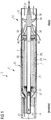
- FIG. 1 is a schematic longitudinal section of an exemplary intravascular blood pump 10.
- the blood pump has a motor section 11 and a pump section 12 which are disposed coaxially one behind the other and result in a rod-shaped construction form.
- the pump section is extended by a flexible suction hose (not shown) which has, at its end and/or in its side wall, openings for the entry of blood to the pump.
- the end of the blood pump 10 facing away from the suction hose is connected to a catheter 14, optionally in combination with a guide wire for steering the blood pump to its destination.
- the exemplary intravascular blood pump shown in Fig. 1 has the motor section 11 and the pump section 12 firmly connected to one another.
- the motor section 11 has an elongate housing 20 in which the electric motor 21 is housed.
- An electric motor has a rotor and a stator.
- the stator is the stationary part of the motor's electromagnetic circuit, while the rotor is the moving part.
- Either the rotor or the stator comprises electrically conductive windings, while the other one comprises permanent magnets. Electrical current flowing in the windings creates an electromagnetic field interacting with the magnetic field of the permanent magnets to generate the forces that turn the rotor.
- the stator 24 of the electric motor 21 has, in the usual way, numerous circumferentially distributed windings as well as a magnetic return path 28 in the longitudinal direction. It is firmly connected to the motor housing.
- the stator 24 surrounds the rotor 1 connected to the motor shaft 25 and consisting of a permanent magnet magnetized in the active direction.
- the motor shaft 25 extends over the total length of the motor housing 20 and protrudes distally out of the latter. There, it carries an impeller 34 with blades 36 projecting therefrom or pump blades which rotate within a tubular pump housing 32 which is in turn firmly connected to the motor housing 20.
- the proximal end of the motor housing 20 has the flexible catheter 14 sealingly attached thereto.
- proximal and distal indicate the position with respect to a physician inserting the intravascular blood pump, i.e. the distal end is at the impeller side.
- electrical cables 23 for power supply to and control of the electric motor 21.
- purge-fluid line 29 which penetrates the proximal end wall 22 of the motor housing 20.
- Purge fluid (schematically illustrated by bold arrows) is fed through the purge-fluid line 29 into the interior of the motor housing 20, flows through clearance 26 between the rotor 1 and the stator 24, and exits through the end face 30 at the distal end of the motor housing.
- the purging pressure is so chosen that it is higher than the blood pressure present, in order to thereby prevent blood from penetrating into the motor housing.
- the pressure of the purge fluid is between 300 and 1400 mmHg at the motor where the pressure is built up.
- a solution of 5% to 40% glucose in water for injection can be used, but physiological saline solution is also suitable.
- the motor shaft 25 is mounted in radial bearings 27 and 31 at the proximal end of the motor housing, on the one hand, and at the distal end of the motor housing, on the other hand. Furthermore, the motor shaft 25 is also mounted axially in an axial bearing 40. Should the blood pump be used for conveying blood also or only in the reverse direction, a corresponding axial bearing 40 is also/only provided at the proximal end of the motor housing 20 in a corresponding manner.
- the blood pump described above is just an example, the present invention also being applicable to different blood pumps comprising an electric motor, i.e. requiring permanent magnets.
- Intravascular blood pumps must meet numerous requirements. Due to their placement within a living body they should be as small as possible. The smallest pumps presently in use have an outer diameter of about 4 mm. Nevertheless, the pumps must convey high volume flows in human blood circulation. Therefore, the minute pumps have to be high-performance engines.
- the implantable blood pumps must not detrimentally influence their biological environment such as the blood to be pumped and the surrounding tissue. Therefore, the pumps should be biocompatible in a broad sense, i.e. they should not contain or produce any potentially noxious materials or considerable heat that might damage the body or constituents thereof.
- intravascular blood pumps should have a long useful life, desirably 180 days or longer.
- an appropriate permanent magnet for the electric motor must be selected.
- the magnet should have a strong magnetic field, i.e. high remanence, high resistance to demagnetization, i.e. high coercivity, and a high saturation magnetization.
- rare earth permanent magnets in particular those having neodymium as the rare earth metal, and especially neodymium iron boron (NdFeB) permanent magnets, are the magnets of choice. Other rare earth iron boron permanent magnets may also be used.
- NdFeB permanent magnets are the strongest permanent magnets currently available. They seem to be ideal for use in intravascular blood pumps.
- NdFeB magnets are available as polymer bonded magnets and as sintered magnets.
- Sintered magnets are superior in magnetic properties. They are prepared by alloying the raw materials, grinding to powder, pressing and sintering. During or after preparation, an external magnetic field is applied in order to magnetize the material.
- a well-studied magnet is a fine-crystalline sintered material wherein Nd 2 Fe 14 B crystals are surrounded by a thin layer particularly rich in neodymium.
- neodymium iron boron magnets While neodymium iron boron magnets have magnetic properties rendering them particularly suitable for use in electric motors of intravascular blood pumps, they also have a serious disadvantage. Namely, commercially available NdFeB magnets, which consist mainly of neodymium, iron and boron, and in particular the sintered neodymium iron boron magnets which have a very active neodymium rich phase at the grain boundaries, are very vulnerable to corrosion.
- the magnets may be, for example, corroded by oxygen and moisture in air, in particular, but not only, at grain boundaries. The corrosion leads to a profound decrease in the magnetic properties, and if the corrosion progresses while the magnet is in use, the performance of the blood pump using the magnet deteriorates. The phenomenon is exacerbated by the tendency of neodymium iron boron magnets to act as a sponge for corrosion products, breaking the structure and leading to spalling off of pieces from the surface of the magnet and finally to
- the magnets In an intravascular blood pump, the magnets have to work in a corrosive environment, namely, in the purging liquid flowing between the rotor and the stator (see Fig. 1 ).
- the purge fluid is typically an aqueous fluid, possibly a fluid containing chloride.
- Chloride is highly corrosive for rare earth metal based magnets, but also water and oxygen dissolved in the water cause severe corrosion within very short time spans of only a few hours.
- rare earth metal based permanent magnets such as neodymium iron boron magnets, for intravascular blood pumps need to be protected against corrosion.
- neodymium iron boron magnets and other rare earth metal based magnets against corrosion are known.
- corrosion resistance may be improved by coating the magnets with protective coatings.
- Usual coatings are nickel coatings and coatings based on epoxy resins, and, especially for blood pumps, titanium coatings and Parylene coatings are known. These coatings, however, also have disadvantages. Even if biocompatible metals and organic resins are respectively selected, such as titanium and Parylene, there is the problem that metal coatings must be relatively thick in order to provide sufficient protection. As a result, the gap between the magnet and the windings in the electric motor of the blood pump must be relatively large. A large gap has a strong negative effect on the performance of the electric motor. A large gap demands a higher motor current, and high motor currents produce undesirable heat which may lead to damage of blood and tissue.
- organic materials such as Parylene have thermal expansion coefficients which are considerably different from the thermal expansion coefficient of the magnet. Therefore, temperature variations during use of the magnet often lead to cracking and/or delamination of the coating.
- the present invention provides a solution to the problems described above.
- the present invention provides a coating for permanent magnets which reliably protects the magnets against corrosion while in use in an intravascular blood pump over an extended period of time.
- the subject-matter of the present invention involves a corrosion resistant permanent magnet having the features recited in independent claim 1, a method for producing a corrosion resistant permanent magnet, the method having the features recited in independent claim 21, and an intravascular blood pump having the features recited in independent claim 30.
- Embodiments of the invention are disclosed in the respective dependent claims.
- a magnet is corrosion resistant in the sense of this invention if it passes the test described in the experimental section.
- a strong permanent magnet comprises a coating either completely surrounding a magnet body or covering at least those surfaces of the magnet body which are exposed to fluid when the magnet is operating in an intravascular blood pump.
- the coating renders the magnet resistant to corrosion while in use in an intravascular blood pump.
- Preferred magnet bodies are sintered magnets consisting primarily of neodymium, iron, and boron, with fine tetragonal magnetic Nd 2 Fe 14 B crystals and a neodymium rich non-magnetic phase surrounding the crystals, as described above.
- the Nd 2 Fe 14 B crystals forming the main phase have a mean crystal diameter within a range of 1 to 80 ⁇ m.
- the non-magnetic neodymium rich phase makes up from 1% to 50% by volume of the magnet body.
- These magnets are readily available commercially. They are preferred because they have high magnetic characteristics, and because they are particularly strong, i.e. have a high flux density.
- an application in intravascular blood pumps requires particularly strong magnets.
- the inventive corrosion resistant coating can be applied to any material requiring protection against corrosion, for example different rare earth iron boron magnetic materials or any other magnetic materials.
- the inventive coating is a composite coating provided on surfaces of the magnet body, i.e. the actual magnetic material.
- the composite coating comprises a metal layer on surfaces of the magnet body, optionally a metal oxide layer on the metal layer at the exposed surfaces thereof, a layer formed from poly(2-chloro-p-xylylene), and a linker layer between the metal layer or the metal oxide layer and the poly(2-chloro-p-xylylene) layer.
- Rare earth metal based magnets as purchased from a supplier are typically protected by a phosphate coating.
- This phosphate coating may be removed, for ex-ample by washing with an acid, prior to application of the metal layer.
- the phosphate coating does not detrimentally interfere with the coating or the coating process according to the present invention and may, therefore, remain on the magnet body.
- the phosphate coating is not removed. Not removing the phosphate coating saves one process step and avoids introduction of impurities during such process step. It is, however, preferable to clean the magnet prior to application of the metal layer. Cleaning is preferably performed by washing the magnet with an organic solvent, for example an alcohol. Particularly preferred cleaning agents are isopropanol and a mixture of isopropanol and ethanol. After washing with an organic solvent, the magnet is dried, for example in vacuum or in an air stream.
- the metal layer is applied to the surface of the magnet body.
- the metal for forming the metal layer is not particularly restricted.
- the term "metal” as used herein must be understood as including metal alloys. Suitable for forming the metal layer are any metals (metal alloys) which can form a dense layer and are biocompatible.
- the method for applying the metal layer is not particularly limited. Exemplary application methods include dry methods such as physical vapor deposition, in particular ion vapor deposition, plasma coating and atomic layer deposition, and wet methods such as galvanic deposition (ion plating). Plasma deposition and ion vapor deposition are quite fast and cost effective methods, but it appears that wet deposition yields metal layers having a better quality, i.e. metal layers having an enhanced density. However, layers deposited by ion vapor deposition or other dry methods have superior long term stability.
- the preferred metal for forming the metal layer is aluminum.
- Galvanic deposition of aluminum is performed out of ionic liquids in a manner usual in the art, for example by using a mixture of aluminum chloride and 1-ethyl-3-methylimidazolium-chloride.
- the aluminum is preferably pure, e.g. at least 99% pure, and particularly preferably at least 99.9% pure.
- Aluminum forms a passivating oxide layer when exposed to air.
- This naturally formed (native) oxide layer is only a few nanometers thin and adheres well to the underlying metal.
- Other metals forming a native oxide layer are also suitable.
- Exemplary metals include titanium, tantalum, niobium, zirconium and alloys of two or more of these metals, e.g. aluminum alloy and niobium titanium alloy.
- oxide layers are formed by oxidation of the metal coated on the magnet body either automatically upon exposure to air or artificially, e.g. by anodic oxidation. In any case, the oxide layer is only a few nanometers thick, e.g. about 2 to 5 nanometers.
- the invention also works well without an oxide layer, and biocompatible metals without an oxide layer may be advantageously used.
- Such metals and metal alloys are, for example, noble metals, e.g. platinum and gold.
- the thickness of the metal layer, and of the combined metal/metal oxide layer is preferably small, i.e. about 20 ⁇ m or less. A thickness of 10 ⁇ m or less is particularly preferred.
- the metal layer or the metal/metal oxide layer is combined with a poly(p-xylylene)polymer layer.
- Poly(p-xylylene)polymers are known under the trade name Parylene. Parylenes may react with hydroxyl group containing surfaces, and are known to form pin-hole free coatings at low layer thicknesses. In addition, they have low dielectric constants (about 3), which is advantageous in implantable blood pumps.
- a composite coating comprising a metal layer or a metal/metal oxide layer and a Parylene layer is biocompatible and also provides corrosion protection.
- the adhesion of the Parylene layer to the metal layer or the metal oxide layer is not sufficiently strong under the working conditions in an intravascular blood pump.
- the Parylene layer starts to delaminate after an unacceptably short time, thus exposing the metal or metal oxide layer.
- the metal layer or the metal/metal oxide layer cannot sufficiently protect the magnet body, and thus corrosion of the magnet body sets in.
- this scenario is prevented by a combination of two measures: provision of an interface layer linking the metal layer or the metal oxide layer and the Parylene layer, and use of a particular Parylene compound.
- the compound forming the interface layer i.e. the linker compound
- the compound forming the interface layer i.e. the linker compound
- Bifunctional means that the linker compound must have two types of functional groups or molecular moieties of different functionality (reactivity), one functional group or molecular moiety bonding to the metal layer or the metal oxide layer, e.g. by reacting with surface hydroxyl groups of the metal or metal oxide layer, and the other functional group or molecular moiety bonding to Parylene, thus firmly linking the inorganic metal layer or metal oxide layer and the organic Parylene layer.
- Linking may be provided by covalent bonds or other bonds, e.g. by van der Waals forces.
- Linkers having functional groups or moieties bonding to metals or metal oxides, and functional groups or moieties bonding to Parylene are known.
- exemplary linkers mention may be made of silane compounds, mercaptans, phosphines, disulfides, and silanes having a thiol, phosphine or disulfide group. Depending on the metal, different linker compounds are preferred.
- linkers for the metal layers and for the metal oxide layers are preferably alkoxysilanes, such as methoxysilanes and ethoxysilanes, for example silanes having the formula (H 3 CO) 3 Si-R, with R being e.g. methacrylate, alkylamine, phenylamine, or epoxyalkyl.
- the linkers preferably have an acryloyloxy or methacryloyloxy functional group.
- the carbon chain length between the silyl portion and the (meth)acryloyloxy portion of the linker typically has from 1 to 16 carbon atoms (methyl, ethyl, propyl, butyl, pentyl.).
- the hydrocarbon chain is typically saturated, but may also contain one or more unsaturated bonds.
- a particularly preferred linker is 3-(trimethoxysilyl)propyl methacrylate (A-174) from Silquest, but other silane compounds such as G-170 from Silquest (a vinyl-functional silane coupling agent) are also suitable.
- linkers having bis-trimethoxysilyl or bis-triethoxysilyl functionalities may be used, for example bis(trimethoxysilylethyl)benzene.
- linkers having hydrid-functional groups such as trihydrosilanes work well. 10-undecenylsilane and n-octadecylsilane may be specifically mentioned.
- the silanes are preferably applied at room temperature from the vapor phase or from an aprotic solution.
- the above-mentioned alkoxysilanes having (meth)acryloyloxy groups, and the compounds having bis-trimethoxysilyl or bis-triethoxysilyl functionalities are also suitable.
- Linkers suitable for linking the Parylene layer to a gold layer are typically mercaptans, phosphines or disulfides, preferably with longer hydrocarbon chains, such as alkyl- or dialkyl-disulfides with alkyl groups having from 10 to 16 carbon atoms.
- alkyl groups form dense and well ordered layers on the metal or metal oxide surface.
- alkyl groups having only from 1 to 9 carbon atoms may also be used.
- silane linker compounds having thiol, phosphine or disulfide groups are particularly preferred examples. Particularly preferred examples are 3-(2-pyridylethyl)thiopropyl trimethoxysilane, 3-(4-pyridylethyl)thiopropyl trimethoxysilane, 2-(diphenylphosphino)ethyl triethoxysilane, bis(2-methacryloyl)oxyethyldisulfide, and dihexadecyldisulfide.
- the bifunctional linkers are preferably applied to the metal or metal oxide surface by a plasma coating process or by physical vapor deposition without plasma or by applying an aprotic, or an alcoholic or an aqueous solution of the bifunctional linker compound to the metal surface or the metal oxide surface.
- Dry coating of silane compounds in a plasma chamber yields glassy layers comprising Si-O-Si-O-chains arranged substantially parallel to the metal oxide surface and bonded to the surface via oxygen atoms.
- An organic residue faces away from the surface and is available for bonding to the Parylene.
- Physical vapor deposition and wet application form interface layers having a similar structure, but without a glassy appearance.
- Plasma deposition yields a dense layer with acceptable adherence to Parylene. Physical vapor deposition without plasma yields less dense layers having better adherence to Parylenes than plasma deposited layers. Wet application yields very dense monolayers having an irregular network and a high degree of crosslinking and a high percentage of silicon-bonded oxygen. These layers also adhere very well to Parylene layers. Therefore, wet application is particularly preferable.
- a glassy interface layer is first formed by plasma deposition, followed by physical vapor deposition or wet application of a second linker layer, thus forming a composite linker layer.
- silicon atoms of the glassy layer are linked covalently to oxygen atoms of the second layer, with organic residues (such as methacrylate, alkylamine, or epoxyalkyl) of the second layer being available for bonding the Parylenes, either covalently or in a different manner, e.g. by van der Waals forces.
- the interface layer typically has a thickness in the range from 20 to 150 nm, preferably from 50 to 100 nm.
- Parylene layer i.e. a poly(p-xylylene)polymer layer
- Poly(p-xylylene)polymers have the structural formula wherein n is the polymerization degree.
- Precursors of poly(p-xylylene) compounds are [2.2]paracyclophanes having the structural formula
- the dimeric compounds are available on the market, for example precursors of Parylene N, Parylene C, Parylene D, and Parylene F.
- Parylene N all of X and R1 to R4 are hydrogen
- Parylene C one of R1 to R4 is chlorine while the other residues R as well as X are hydrogen
- Parylene D two of the residues R1 to R4 are chlorine while all other residues are hydrogen
- Parylene F the residues X are fluorine while the residues R1 to R4 are hydrogen.
- Parylene layers are typically used as moisture barriers and dielectric barriers.
- the dimers are cracked to form the corresponding p-xylylene radicals.
- the monomers polymerize to form poly(p-xylylene) polymers, on the one hand, and bond to the interface layer via the functional groups thereof, e.g. methacrylate groups, on the other hand. Alternatively, they may simply adhere to hydrophobic portions of the interface layer.
- Parylene C wherein one of R1 to R4 is chlorine, forms a coating rendering magnetic materials resistant to corrosion under the conditions encountered in intravascular blood pumps, when applied as the cover layer of the composite layer described above.
- the Parylene C layer is preferably applied by plasma deposition, and the layer thickness is preferably in a range from 5 to 20 ⁇ m, more preferably from 10 to 16 ⁇ m.
- Parylene C When Parylene C is applied directly onto the surface of the magnetic material, crack formation and delamination of the protective Parylene C layer and corrosion of the magnetic material are observed within a few days. Likewise, if Parylene C is applied onto a metal layer or a metal/metal oxide layer, corrosion of the magnetic material is observed under the conditions in an intravascular blood pump within an unacceptably short time period, due to delamination. In addition, Parylene compounds different from Parylene C do not provide sufficient corrosion protection, even if an adhesion promoter is used, e.g. if applied on a silane based interface layer.
- the composite coating of the present invention adheres well to the magnet body, and since it has a structure made up of both inorganic and organic constituents, it provides an effective barrier against both inorganic and organic matter.
- glassy interface layers have barrier properties, too.
- corrosion protection of the magnetic material is further enhanced by the shape of the magnet body being particularly adapted to allow the formation of a coating covering the magnet body with a uniform thickness.
- the magnet body has no sharp edges, but rather rounded forms such as soft edges.
- the magnet body is rod-shaped having a channel extending therethrough in a longitudinal direction for receiving the motor shaft of an intravascular blood pump, the opposing front faces of the magnet body being bevelled towards the channel.
- the channel does not need to be coated with the composite coating because in an intravascular blood pump the channel receives the motor shaft and is fixed thereto.
- the channel may be coated nevertheless, to be on the safe side.
- the magnet body may be a single piece, or may be composed of several segments.
- each segment is provided with the inventive coating either surrounding it completely or at least the exposed surfaces thereof with a uniform thickness.
- each segment has soft edges.
- the intravascular blood pump 10 illustrated in Fig. 1 has been described above.
- the pump is conventional in construction, but comprises a corrosion resistant permanent magnet 1 according to the present invention.
- the magnet 1 is rod-shaped, the opposing front faces being flat and parallel to each other.
- the composite coating according to the present invention may effectively protect a magnet body having sharp edges as illustrated in Fig. 1 against corrosion over an extended period of time, it is preferred in the present invention to use a magnet body having a shape as illustrated in Figs. 2 and 3 .
- the individual layers of the composite coating completely extend over each previously applied composite coating layer.
- Fig. 2a shows a single-piece magnet 1 having a rod shape and a bore or channel extending therethrough in a longitudinal direction.
- the channel receives the motor shaft 25.
- the opposing front faces 4 of the magnet are tapered towards the channel.
- the magnet 1 is provided with a composite coating according to the invention at the outer surfaces 2 exposed to the fluid flowing in gap 26 and the tapered front faces 4.
- the inner surfaces 3 adjacent to the motor shaft 25 may or may not be coated.
- Edge 5 at the transition between the outer surface 2 and the front surface 4, as well as edge 6 at the transition between front surface 4 and the inner surface 3, are coated. The edges are soft, thus facilitating the formation of a well-adhering uniform coating.
- "N" and "S” indicate the north pole and the south pole of the magnet.
- Fig 2b is a partial sectional view along the dash-dot line in Fig. 2a.
- Fig. 2b shows the region of the magnet within the loop in Fig. 2a.
- Fig. 2b clearly shows the soft edges 5, 6.
- Fig. 3 shows a segmented magnet 7.
- the magnet illustrated in Fig. 3 has four segments 8, 8'. Segments 8, which are opposite to one another, have the same magnetic polarity, as indicated by "N” in the top view of Fig. 3 , and segments 8', which are also opposite to one another, have the same magnetic polarity, as indicated by "S” in the top view of Fig. 3 . As a result, adjacent segments 8, 8' have opposite magnetic polarity.
- Segments 8, 8' have, analogously to the single-piece magnet shown in Fig. 2 , inner surfaces, outer surfaces, opposing front faces, edges at the transition between the outer surfaces and the front surfaces, and edges at the transition between the front surfaces and the inner surfaces. Front faces are designated 4', and the edges are designated 5' and 6', respectively, in correspondence to the designations in Fig. 2 .
- segments 8, 8' have side surfaces 9, 9', separated by gaps in the drawing. Of course, when the magnet is in use, side surfaces 9, 9' contact each other. All surfaces of each segment of the magnet may be completely covered by the inventive composite coating, but side surfaces 9, 9' which are not exposed because they contact each other, and the inner surfaces which are not exposed because they contact the motor shaft, do not need to be coated. Preferably all edges of all segments are soft edges.
- Table 1 illustrates the results of corrosion testing of niobium iron boron magnets coated with different coatings. Twelve identical cylindrical non-magnetized Nd 2 Fe 14 B sintered magnet bodies having a length of 12 mm and a diameter of 2.8 mm were coated as described below, and subjected to corrosion testing in an aqueous solution containing 0.9 weight% sodium chloride at 60°C. Test specimens were inspected daily until day 60, and thereafter inspected once a week. Corrosion of the magnetic material results in lifting or deformation of the coating. Thus, lifting of the coating or formation of a bulge at a surface of a test specimen indicates corrosion of the magnetic material. Formation of a bulge having a height of 0.1 mm as well as lifting of the coating were defined as being indicative of magnet failure.
- Test specimens were prepared in the following manner:
- Non-magnetized neodymium iron boron magnet bodies (with phosphate passivation as purchased) were cleaned with isopropanol and then dried in an air stream. Then, coatings were applied, and after application of the coatings, the coated magnets were subjected to magnetization in a magnetic field. Magnetizing the magnet bodies before applying the inventive composite coating is not appropriate. Coating thicknesses were about 7 ⁇ m for the aluminum layer, about 100 nm for the silane layer, and about 10 ⁇ m for the Parylene layer, where applicable.
- Specimens 1 and 2 the dry magnet bodies were coated with aluminum by ion vapor deposition. Upon exposure to air, an aluminum oxide layer (native aluminum oxide layer) formed. Then, Parylene C was plasma coated thereon.
- Specimens 3 and 4 the dry magnet bodies were coated with aluminum by ion vapor deposition. Upon exposure to air, a native aluminum oxide layer formed at the exposed surface of the aluminum layer. No further coating was applied.
- Specimen 5 the dry magnet body was coated with aluminum by ion vapor deposition. Upon exposure to air, a native aluminum oxide layer formed. Then, 3-(trimethoxysilyl)propyl methacrylate (silane A-174) was applied by plasma coating, followed by application of Parylene F by plasma coating.
- silane A-174 3-(trimethoxysilyl)propyl methacrylate
- Specimens 6 and 7 the dry magnet bodies were coated with aluminum by ion vapor deposition. Upon exposure to air, a native aluminum oxide layer formed. Then, an alcoholic solution (water/ethanol; acetic acid to achieve a pH of about 5 to 6; concentration of silane about 1%; reaction time about 5 minutes) containing silane A-174 was applied, and the alcohol evaporated. Finally, Parylene C was applied by plasma coating.
- Specimen 8 the dry magnet body was coated with aluminum by ion vapor deposition. Upon exposure to air, a native aluminum oxide layer formed. Then, silane A-174 was applied by plasma coating, followed by application of Parylene C by plasma coating.
- Ion vapor deposition for specimen 1 to 8 was performed in argon gas at about 10- 3 mbar at a potential of about 1000 volts and 1500 amperes DC. Generally, from about 400 to 1000 volts and from about 500 to 1500 amperes DC are suitable.
- Specimens 9 and 10 the dry magnet bodies were coated with a copolymer of ethylene and chlorotrifluoroethylene by spray coating. The coated magnets were subjected to baking, and then cooled.
- Specimens 11 and 12 the dry magnet bodies were spray coated with polyphenylene sulfide resin and baked at 135°C for thirty minutes.
- Table 1 Specimen # Time t until failure invention comparative t ⁇ 3 days 3 days ⁇ t ⁇ 1 month t ⁇ 6 months 1 x 2 x 3 x 4 x 5 x 6 x 7 x 8 x 9 x 10 x 11 x 12 x
- a magnet is corrosion resistant in terms of this invention when it passes the test, i.e. time until failure is at least 180 days
- Specimen samples 9, 10, 11, and 12 each having a resin coating according to the state of the art directly applied to the neodymium iron boron magnet body, failed within less than 3 days in sodium chloride solution at 60°C.
- Specimen samples 1 to 5 comprising protective aluminum/aluminum oxide layers survived for a longer time.
- Specimen samples 3 and 4 which were corrosion protected by aluminum/aluminum oxide layers without any additional protective layers failed within less than 1 month.
- the same result was achieved when a coating consisting of Parylene C was applied directly onto the aluminum oxide layer, i.e. without a silane based interface layer (specimen samples 1 and 2). Additionally, the same result was achieved when a silane based interface layer was present between the aluminum oxide layer and the Parylene layer, but the Parylene layer did not consist of Parylene C (specimen sample 5).
- Specimen sample 8 had essentially the same coating composition as specimen sample 5, and the individual layers of the composite coating were applied in the same manner. However, in specimen sample 8 Parylene C was used rather than the Parylene F of specimen sample 5. Surprisingly, this slight modification had the consequence that specimen sample 8 did not fail even after 6 months, while specimen sample 5 already failed within less than 1 month.
- specimen samples 6 and 7 were identical to the coating composition of specimen sample 8. However, in specimen sample 8 the interface layer was applied by plasma coating, while in specimen samples 6 and 7 a wet process was used for applying the interface layer. As a result, specimen samples 6 and 7 were still without any sign of corrosion when the test was stopped after one year, while specimen sample 8 did not survive twelve months in a corrosive environment.
- a neodymium iron boron permanent magnet having a composite coating comprising a metal layer, a linker layer and an outer layer formed from poly(2-chloro-p-xylylene) has excellent corrosion resistance even under aggressive conditions, and may be advantageously used in an intravascular blood pump.
- the test results also indicate that the application method of the linker layer influences the corrosion resistance. A particularly excellent corrosion resistance was achieved when the linker layer was applied by a wet process.
- Specimen samples 6, 7 and 8 fulfilled both the above conditions.
- Non-magnetized magnet bodies were coated with the inventive composite coating, and magnetized after application of the complete composite coating.
- specimen samples 6, 7 and 8 did not show any coating lifting, and buckling was less than 0.1 mm in 0.9 weight% NaCl solution at 60°C for at least 180 days. Therefore, specimen samples 6, 7 and 8 are corrosion resistant magnets.
Priority Applications (14)
| Application Number | Priority Date | Filing Date | Title |
|---|---|---|---|
| EP16196804.5A EP3319098A1 (en) | 2016-11-02 | 2016-11-02 | Intravascular blood pump comprising corrosion resistant permanent magnet |
| CN201780068060.9A CN109891533B (zh) | 2016-11-02 | 2017-10-25 | 含有耐腐蚀永磁体的血管内血泵 |
| US16/346,198 US11107626B2 (en) | 2016-11-02 | 2017-10-25 | Intravascular blood pump comprising corrosion resistant permanent magnet |
| JP2019523602A JP7402044B2 (ja) | 2016-11-02 | 2017-10-25 | 耐腐食性永久磁石を備えた血管内血液ポンプ |
| ES17787206T ES2824730T3 (es) | 2016-11-02 | 2017-10-25 | Bomba de sangre intravascular que comprende un imán permanente resistente a la corrosión |
| KR1020197015775A KR102407882B1 (ko) | 2016-11-02 | 2017-10-25 | 내식 영구 자석을 포함하는 혈관 내 혈액 펌프 |
| EP20197483.9A EP3780041A1 (en) | 2016-11-02 | 2017-10-25 | Corrosion resistant permanent magnet |
| KR1020227019221A KR20220082941A (ko) | 2016-11-02 | 2017-10-25 | 내식 영구 자석을 포함하는 혈관 내 혈액 펌프 |
| EP17787206.6A EP3535768B1 (en) | 2016-11-02 | 2017-10-25 | Intravascular blood pump comprising corrosion resistant permanent magnet |
| CN202111618297.4A CN114464390A (zh) | 2016-11-02 | 2017-10-25 | 含有耐腐蚀永磁体的血管内血泵 |
| DK17787206.6T DK3535768T3 (da) | 2016-11-02 | 2017-10-25 | Intravaskulær blodpumpe omfattende korrosionsresistent permanent magnet |
| PCT/EP2017/077334 WO2018082987A1 (en) | 2016-11-02 | 2017-10-25 | Intravascular blood pump comprising corrosion resistant permanent magnet |
| US17/385,319 US11967454B2 (en) | 2016-11-02 | 2021-07-26 | Intravascular blood pump comprising corrosion resistant permanent magnet |
| JP2022135033A JP2022177015A (ja) | 2016-11-02 | 2022-08-26 | 耐腐食性永久磁石を備えた血管内血液ポンプ |
Applications Claiming Priority (1)
| Application Number | Priority Date | Filing Date | Title |
|---|---|---|---|
| EP16196804.5A EP3319098A1 (en) | 2016-11-02 | 2016-11-02 | Intravascular blood pump comprising corrosion resistant permanent magnet |
Publications (1)
| Publication Number | Publication Date |
|---|---|
| EP3319098A1 true EP3319098A1 (en) | 2018-05-09 |
Family
ID=57226824
Family Applications (3)
| Application Number | Title | Priority Date | Filing Date |
|---|---|---|---|
| EP16196804.5A Withdrawn EP3319098A1 (en) | 2016-11-02 | 2016-11-02 | Intravascular blood pump comprising corrosion resistant permanent magnet |
| EP17787206.6A Active EP3535768B1 (en) | 2016-11-02 | 2017-10-25 | Intravascular blood pump comprising corrosion resistant permanent magnet |
| EP20197483.9A Pending EP3780041A1 (en) | 2016-11-02 | 2017-10-25 | Corrosion resistant permanent magnet |
Family Applications After (2)
| Application Number | Title | Priority Date | Filing Date |
|---|---|---|---|
| EP17787206.6A Active EP3535768B1 (en) | 2016-11-02 | 2017-10-25 | Intravascular blood pump comprising corrosion resistant permanent magnet |
| EP20197483.9A Pending EP3780041A1 (en) | 2016-11-02 | 2017-10-25 | Corrosion resistant permanent magnet |
Country Status (8)
| Country | Link |
|---|---|
| US (2) | US11107626B2 (da) |
| EP (3) | EP3319098A1 (da) |
| JP (2) | JP7402044B2 (da) |
| KR (2) | KR20220082941A (da) |
| CN (2) | CN114464390A (da) |
| DK (1) | DK3535768T3 (da) |
| ES (1) | ES2824730T3 (da) |
| WO (1) | WO2018082987A1 (da) |
Cited By (5)
| Publication number | Priority date | Publication date | Assignee | Title |
|---|---|---|---|---|
| EP3567619A1 (en) | 2018-05-08 | 2019-11-13 | Abiomed Europe GmbH | Corrosion-resistant permanent magnet and intravascular blood pump comprising the magnet |
| EP3822996A1 (en) | 2019-11-12 | 2021-05-19 | Abiomed Europe GmbH | Corrosion-resistant permanent magnet for an intravascular blood pump |
| WO2021142490A1 (en) * | 2020-01-10 | 2021-07-15 | Abiomed, Inc. | Blood pump with improved leakage control |
| US11632015B2 (en) | 2018-08-28 | 2023-04-18 | Boston Scientific Scimed, Inc. | Axial flux motor for percutaneous circulatory support device |
| US11967454B2 (en) | 2016-11-02 | 2024-04-23 | Abiomed Europe Gmbh | Intravascular blood pump comprising corrosion resistant permanent magnet |
Families Citing this family (13)
| Publication number | Priority date | Publication date | Assignee | Title |
|---|---|---|---|---|
| EP3634528B1 (en) | 2017-06-07 | 2023-06-07 | Shifamed Holdings, LLC | Intravascular fluid movement devices, systems, and methods of use |
| CN111556763B (zh) | 2017-11-13 | 2023-09-01 | 施菲姆德控股有限责任公司 | 血管内流体运动装置、系统 |
| DE102018201030A1 (de) | 2018-01-24 | 2019-07-25 | Kardion Gmbh | Magnetkuppelelement mit magnetischer Lagerungsfunktion |
| EP4085965A1 (en) | 2018-02-01 | 2022-11-09 | Shifamed Holdings, LLC | Intravascular blood pumps and methods of use and manufacture |
| DE102018211327A1 (de) | 2018-07-10 | 2020-01-16 | Kardion Gmbh | Laufrad für ein implantierbares, vaskuläres Unterstützungssystem |
| TWI716929B (zh) * | 2019-07-08 | 2021-01-21 | 佳磁綠能股份有限公司 | 低磁漏流體磁化器 |
| US11964145B2 (en) | 2019-07-12 | 2024-04-23 | Shifamed Holdings, Llc | Intravascular blood pumps and methods of manufacture and use |
| US11654275B2 (en) | 2019-07-22 | 2023-05-23 | Shifamed Holdings, Llc | Intravascular blood pumps with struts and methods of use and manufacture |
| US11724089B2 (en) | 2019-09-25 | 2023-08-15 | Shifamed Holdings, Llc | Intravascular blood pump systems and methods of use and control thereof |
| WO2021127503A1 (en) * | 2019-12-19 | 2021-06-24 | Shifamed Holdings, Llc | Intravascular blood pumps, motors, and fluid control |
| DE102020102474A1 (de) | 2020-01-31 | 2021-08-05 | Kardion Gmbh | Pumpe zum Fördern eines Fluids und Verfahren zum Herstellen einer Pumpe |
| CN112786301B (zh) * | 2020-12-30 | 2022-10-14 | 包头天和磁材科技股份有限公司 | 耐腐蚀的钕铁硼磁体及表面处理方法和羟基化合物的用途 |
| CN114086116A (zh) * | 2021-11-17 | 2022-02-25 | 安徽通灵仿生科技有限公司 | 导管泵马达转子表面耐腐蚀涂层及其制备工艺 |
Citations (3)
| Publication number | Priority date | Publication date | Assignee | Title |
|---|---|---|---|---|
| US20030041920A1 (en) * | 2000-07-17 | 2003-03-06 | Hiroyuki Hoshi | Coated r-t-b magnet and method for preparation thereof |
| US20080200750A1 (en) * | 2006-11-17 | 2008-08-21 | Natalie James | Polymer encapsulation for medical device |
| WO2016118735A1 (en) * | 2015-01-22 | 2016-07-28 | Medtronic Xomed, Inc. | Corrosion-resistant magnetic article |
Family Cites Families (30)
| Publication number | Priority date | Publication date | Assignee | Title |
|---|---|---|---|---|
| JPH079846B2 (ja) * | 1989-02-09 | 1995-02-01 | 日立金属株式会社 | 耐食性良好な永久磁石およびその製造方法 |
| JP2882484B2 (ja) * | 1989-03-22 | 1999-04-12 | ティーディーケイ株式会社 | 高耐食性稀土類鉄系磁石及びその製造方法 |
| JP2753588B2 (ja) | 1989-07-10 | 1998-05-20 | ティーディーケイ株式会社 | p―キシリレン重合膜を有する稀土類鉄系合金焼結磁石とその製造法 |
| US5154978A (en) * | 1989-03-22 | 1992-10-13 | Tdk Corporation | Highly corrosion-resistant rare-earth-iron magnets |
| TW326423B (en) | 1993-08-06 | 1998-02-11 | Gould Inc | Metallic foil with adhesion promoting layer |
| DE19613564C1 (de) | 1996-04-04 | 1998-01-08 | Guenter Prof Dr Rau | Intravasale Blutpumpe |
| JPH09289108A (ja) * | 1996-04-19 | 1997-11-04 | Sumitomo Special Metals Co Ltd | 密着性のすぐれた電気絶縁性被膜を有するR−Fe−B系永久磁石とその製造方法 |
| JPH1070114A (ja) | 1996-08-28 | 1998-03-10 | Fuji Electric Co Ltd | 有機材料コーティング方法 |
| JP3427296B2 (ja) | 1997-01-14 | 2003-07-14 | コニカ株式会社 | 圧電セラミック素子及びその電極の保護方法 |
| US6062679A (en) | 1997-08-28 | 2000-05-16 | Hewlett-Packard Company | Printhead for an inkjet cartridge and method for producing the same |
| JP4245694B2 (ja) * | 1997-09-26 | 2009-03-25 | ヒューレット・パッカード・カンパニー | 薄膜プリントヘッド |
| JP2000256878A (ja) * | 1999-03-09 | 2000-09-19 | Sumitomo Metal Mining Co Ltd | 高耐食性膜付き部材及びその製造方法 |
| JP2002212750A (ja) | 2000-11-20 | 2002-07-31 | Hitachi Metals Ltd | R−t−b系磁石の皮膜形成方法 |
| CN1129487C (zh) * | 2001-01-22 | 2003-12-03 | 孙泉 | 钕铁硼永磁表面聚对二甲苯耐蚀涂层制备预清洗工艺 |
| JP2004064895A (ja) * | 2002-07-29 | 2004-02-26 | Seiko Epson Corp | 永久磁石の製造方法、永久磁石、モータ用部品およびモータ |
| JP2005210095A (ja) | 2003-12-25 | 2005-08-04 | Tdk Corp | 希土類磁石の製造方法 |
| JP2006351946A (ja) | 2005-06-17 | 2006-12-28 | Fuji Electric Holdings Co Ltd | 軟磁性成形体の製造方法 |
| CN100464007C (zh) * | 2006-07-14 | 2009-02-25 | 西南大学 | 钕铁硼永磁材料表面梯度功能涂层制备方法 |
| US7767589B2 (en) | 2007-02-07 | 2010-08-03 | Raytheon Company | Passivation layer for a circuit device and method of manufacture |
| EP2131888B1 (en) * | 2007-02-26 | 2017-04-05 | HeartWare, Inc. | Intravascular ventricular assist device |
| JP4978665B2 (ja) * | 2009-06-29 | 2012-07-18 | Tdk株式会社 | 金属磁石及びそれを用いたモータ |
| US8313819B2 (en) | 2009-08-12 | 2012-11-20 | Medos International S.A.R.L. | Ultra-thin multi-layer packaging |
| JP5644738B2 (ja) * | 2011-11-04 | 2014-12-24 | 日立化成株式会社 | 希土類鉄系磁石の膜形成のための処理液及び希土類鉄系磁石の製造方法 |
| JP2012119338A (ja) | 2012-02-15 | 2012-06-21 | Pioneer Electronic Corp | 電子デバイス |
| US9345813B2 (en) | 2012-06-07 | 2016-05-24 | Medos International S.A.R.L. | Three dimensional packaging for medical implants |
| WO2014178798A1 (en) * | 2013-05-02 | 2014-11-06 | Tera-Barrier Films Pte Ltd | Encapsulation barrier stack comprising dendrimer encapsulated nanop articles |
| JPWO2015190409A1 (ja) | 2014-06-12 | 2017-04-20 | コニカミノルタ株式会社 | インクジェットヘッド及びインクジェット記録装置 |
| JP2016134454A (ja) | 2015-01-16 | 2016-07-25 | 四国化成工業株式会社 | レジスト層と、基材または金属層を接着する為の表面処理液、表面処理方法およびレジスト層用樹脂組成物 |
| EP3319098A1 (en) | 2016-11-02 | 2018-05-09 | Abiomed Europe GmbH | Intravascular blood pump comprising corrosion resistant permanent magnet |
| ES2842882T3 (es) | 2018-05-08 | 2021-07-15 | Abiomed Europe Gmbh | Imán permanente resistente a la corrosión y bomba de sangre intravascular que comprende el imán |
-
2016
- 2016-11-02 EP EP16196804.5A patent/EP3319098A1/en not_active Withdrawn
-
2017
- 2017-10-25 JP JP2019523602A patent/JP7402044B2/ja active Active
- 2017-10-25 KR KR1020227019221A patent/KR20220082941A/ko not_active Application Discontinuation
- 2017-10-25 DK DK17787206.6T patent/DK3535768T3/da active
- 2017-10-25 EP EP17787206.6A patent/EP3535768B1/en active Active
- 2017-10-25 KR KR1020197015775A patent/KR102407882B1/ko active IP Right Grant
- 2017-10-25 US US16/346,198 patent/US11107626B2/en active Active
- 2017-10-25 WO PCT/EP2017/077334 patent/WO2018082987A1/en unknown
- 2017-10-25 EP EP20197483.9A patent/EP3780041A1/en active Pending
- 2017-10-25 ES ES17787206T patent/ES2824730T3/es active Active
- 2017-10-25 CN CN202111618297.4A patent/CN114464390A/zh active Pending
- 2017-10-25 CN CN201780068060.9A patent/CN109891533B/zh active Active
-
2021
- 2021-07-26 US US17/385,319 patent/US11967454B2/en active Active
-
2022
- 2022-08-26 JP JP2022135033A patent/JP2022177015A/ja active Pending
Patent Citations (3)
| Publication number | Priority date | Publication date | Assignee | Title |
|---|---|---|---|---|
| US20030041920A1 (en) * | 2000-07-17 | 2003-03-06 | Hiroyuki Hoshi | Coated r-t-b magnet and method for preparation thereof |
| US20080200750A1 (en) * | 2006-11-17 | 2008-08-21 | Natalie James | Polymer encapsulation for medical device |
| WO2016118735A1 (en) * | 2015-01-22 | 2016-07-28 | Medtronic Xomed, Inc. | Corrosion-resistant magnetic article |
Cited By (10)
| Publication number | Priority date | Publication date | Assignee | Title |
|---|---|---|---|---|
| US11967454B2 (en) | 2016-11-02 | 2024-04-23 | Abiomed Europe Gmbh | Intravascular blood pump comprising corrosion resistant permanent magnet |
| EP3567619A1 (en) | 2018-05-08 | 2019-11-13 | Abiomed Europe GmbH | Corrosion-resistant permanent magnet and intravascular blood pump comprising the magnet |
| WO2019214920A1 (en) | 2018-05-08 | 2019-11-14 | Abiomed Europe Gmbh | Corrosion-resistant permanent magnet and intravascular blood pump comprising the magnet |
| US11569015B2 (en) | 2018-05-08 | 2023-01-31 | Abiomed Europe Gmbh | Corrosion-resistant permanent magnet and intravascular blood pump comprising the magnet |
| US11632015B2 (en) | 2018-08-28 | 2023-04-18 | Boston Scientific Scimed, Inc. | Axial flux motor for percutaneous circulatory support device |
| EP3822996A1 (en) | 2019-11-12 | 2021-05-19 | Abiomed Europe GmbH | Corrosion-resistant permanent magnet for an intravascular blood pump |
| WO2021094297A1 (en) | 2019-11-12 | 2021-05-20 | Abiomed Europe Gmbh | Corrosion-resistant permanent magnet for an intravascular blood pump |
| DE112020005559T5 (de) | 2019-11-12 | 2022-09-22 | Abiomed Europe Gmbh | Korrosionsbeständiger permanentmagnet für eine intravaskuläre blutpumpe |
| EP4095872A1 (en) | 2019-11-12 | 2022-11-30 | Abiomed Europe GmbH | Corrosion-resistant permanent magnet for an intravascular blood pump |
| WO2021142490A1 (en) * | 2020-01-10 | 2021-07-15 | Abiomed, Inc. | Blood pump with improved leakage control |
Also Published As
| Publication number | Publication date |
|---|---|
| WO2018082987A1 (en) | 2018-05-11 |
| JP2020503083A (ja) | 2020-01-30 |
| EP3535768B1 (en) | 2020-09-23 |
| JP2022177015A (ja) | 2022-11-30 |
| EP3780041A1 (en) | 2021-02-17 |
| CN109891533B (zh) | 2022-01-11 |
| EP3535768A1 (en) | 2019-09-11 |
| JP7402044B2 (ja) | 2023-12-20 |
| KR20220082941A (ko) | 2022-06-17 |
| US11967454B2 (en) | 2024-04-23 |
| US11107626B2 (en) | 2021-08-31 |
| KR102407882B1 (ko) | 2022-06-10 |
| US20190311850A1 (en) | 2019-10-10 |
| US20220051847A1 (en) | 2022-02-17 |
| ES2824730T3 (es) | 2021-05-13 |
| CN114464390A (zh) | 2022-05-10 |
| KR20190070991A (ko) | 2019-06-21 |
| DK3535768T3 (da) | 2020-10-19 |
| CN109891533A (zh) | 2019-06-14 |
Similar Documents
| Publication | Publication Date | Title |
|---|---|---|
| US11967454B2 (en) | Intravascular blood pump comprising corrosion resistant permanent magnet | |
| US11569015B2 (en) | Corrosion-resistant permanent magnet and intravascular blood pump comprising the magnet | |
| EP3899994B1 (en) | Corrosion-resistant permanent magnet for an intravascular blood pump |
Legal Events
| Date | Code | Title | Description |
|---|---|---|---|
| PUAI | Public reference made under article 153(3) epc to a published international application that has entered the european phase |
Free format text: ORIGINAL CODE: 0009012 |
|
| AK | Designated contracting states |
Kind code of ref document: A1 Designated state(s): AL AT BE BG CH CY CZ DE DK EE ES FI FR GB GR HR HU IE IS IT LI LT LU LV MC MK MT NL NO PL PT RO RS SE SI SK SM TR |
|
| AX | Request for extension of the european patent |
Extension state: BA ME |
|
| 17P | Request for examination filed |
Effective date: 20180705 |
|
| RBV | Designated contracting states (corrected) |
Designated state(s): AL AT BE BG CH CY CZ DE DK EE ES FI FR GB GR HR HU IE IS IT LI LT LU LV MC MK MT NL NO PL PT RO RS SE SI SK SM TR |
|
| STAA | Information on the status of an ep patent application or granted ep patent |
Free format text: STATUS: EXAMINATION IS IN PROGRESS |
|
| 17Q | First examination report despatched |
Effective date: 20201111 |
|
| STAA | Information on the status of an ep patent application or granted ep patent |
Free format text: STATUS: THE APPLICATION HAS BEEN WITHDRAWN |
|
| 18W | Application withdrawn |
Effective date: 20210316 |