EP3318205A1 - Instrument de traitement pour endoscope - Google Patents
Instrument de traitement pour endoscope Download PDFInfo
- Publication number
- EP3318205A1 EP3318205A1 EP16817548.7A EP16817548A EP3318205A1 EP 3318205 A1 EP3318205 A1 EP 3318205A1 EP 16817548 A EP16817548 A EP 16817548A EP 3318205 A1 EP3318205 A1 EP 3318205A1
- Authority
- EP
- European Patent Office
- Prior art keywords
- metal coil
- distal
- sheath member
- resin tube
- radial direction
- Prior art date
- Legal status (The legal status is an assumption and is not a legal conclusion. Google has not performed a legal analysis and makes no representation as to the accuracy of the status listed.)
- Granted
Links
Images


Classifications
-
- A—HUMAN NECESSITIES
- A61—MEDICAL OR VETERINARY SCIENCE; HYGIENE
- A61B—DIAGNOSIS; SURGERY; IDENTIFICATION
- A61B17/00—Surgical instruments, devices or methods, e.g. tourniquets
- A61B17/22—Implements for squeezing-off ulcers or the like on the inside of inner organs of the body; Implements for scraping-out cavities of body organs, e.g. bones; Calculus removers; Calculus smashing apparatus; Apparatus for removing obstructions in blood vessels, not otherwise provided for
- A61B17/221—Gripping devices in the form of loops or baskets for gripping calculi or similar types of obstructions
-
- A—HUMAN NECESSITIES
- A61—MEDICAL OR VETERINARY SCIENCE; HYGIENE
- A61B—DIAGNOSIS; SURGERY; IDENTIFICATION
- A61B17/00—Surgical instruments, devices or methods, e.g. tourniquets
- A61B2017/00831—Material properties
- A61B2017/0084—Material properties low friction
- A61B2017/00845—Material properties low friction of moving parts with respect to each other
-
- A—HUMAN NECESSITIES
- A61—MEDICAL OR VETERINARY SCIENCE; HYGIENE
- A61B—DIAGNOSIS; SURGERY; IDENTIFICATION
- A61B17/00—Surgical instruments, devices or methods, e.g. tourniquets
- A61B2017/00831—Material properties
- A61B2017/00853—Material properties low friction, hydrophobic and corrosion-resistant fluorocarbon resin coating (ptf, ptfe, polytetrafluoroethylene)
-
- A—HUMAN NECESSITIES
- A61—MEDICAL OR VETERINARY SCIENCE; HYGIENE
- A61B—DIAGNOSIS; SURGERY; IDENTIFICATION
- A61B17/00—Surgical instruments, devices or methods, e.g. tourniquets
- A61B17/22—Implements for squeezing-off ulcers or the like on the inside of inner organs of the body; Implements for scraping-out cavities of body organs, e.g. bones; Calculus removers; Calculus smashing apparatus; Apparatus for removing obstructions in blood vessels, not otherwise provided for
- A61B17/221—Gripping devices in the form of loops or baskets for gripping calculi or similar types of obstructions
- A61B2017/2212—Gripping devices in the form of loops or baskets for gripping calculi or similar types of obstructions having a closed distal end, e.g. a loop
-
- A—HUMAN NECESSITIES
- A61—MEDICAL OR VETERINARY SCIENCE; HYGIENE
- A61B—DIAGNOSIS; SURGERY; IDENTIFICATION
- A61B17/00—Surgical instruments, devices or methods, e.g. tourniquets
- A61B17/22—Implements for squeezing-off ulcers or the like on the inside of inner organs of the body; Implements for scraping-out cavities of body organs, e.g. bones; Calculus removers; Calculus smashing apparatus; Apparatus for removing obstructions in blood vessels, not otherwise provided for
- A61B17/221—Gripping devices in the form of loops or baskets for gripping calculi or similar types of obstructions
- A61B2017/2215—Gripping devices in the form of loops or baskets for gripping calculi or similar types of obstructions having an open distal end
-
- A—HUMAN NECESSITIES
- A61—MEDICAL OR VETERINARY SCIENCE; HYGIENE
- A61B—DIAGNOSIS; SURGERY; IDENTIFICATION
- A61B17/00—Surgical instruments, devices or methods, e.g. tourniquets
- A61B17/28—Surgical forceps
- A61B17/29—Forceps for use in minimally invasive surgery
- A61B2017/2901—Details of shaft
- A61B2017/2905—Details of shaft flexible
Definitions
- the present invention relates to an endoscope treatment tool.
- the basket in which the calculus is captured is pulled into a sheath from a distal-end opening in the sheath, the basket is contracted, and thus, the calculus is crushed by squeezing the calculus by contracting the basket.
- Patent Literature 1 a coil sheath having excellent compression resistance is used. Also, a resin inner cylinder is disposed on the inner side of the coil sheath in order to reduce the friction due to irregularities on the inner surface of the coil sheath, and thus, a smooth motion of the basket is ensured.
- the lateral cross-section of the strand constituting the coil sheath has a circular shape
- the calculus-collecting endoscope treatment tool is temporarily removed, and, if necessary, the endoscope itself is also exchanged with one having a large channel, after which the calculus-crushing endoscope treatment tool needs to be reinserted, thus prolonging the operation and increasing the burden on the patient.
- the collected calculus captured in the calculus-collecting basket is stuck in the basket, it is difficult to exchange the endoscope treatment tool, and thus, there is a problem in that the burden on the patient is further increased.
- the present invention has been conceived in light of the above-described circumstances, and an object thereof is to provide an endoscope treatment tool with which it is possible to enhance the compression resistance of a sheath and to enhance the insertability into the bile duct or the like by reducing the diameter while maintaining a moderate flexural rigidity.
- the present invention provides the following solutions.
- An aspect of the present invention is an endoscope treatment tool including: a tubular sheath member that can be inserted into a channel of an endoscope; a wire that is inserted into an interior of the sheath member in such a manner that the wire can be advanced/retracted in a longitudinal direction of the sheath member; and a distal-end treating portion that is provided at a distal end of the wire and that is made to protrude from/be pulled into a distal-end opening in the sheath member by advancing/retracting the wire, wherein the sheath member is configured having a two-layer structure in which a metal coil and a resin tube are layered in a radial direction and secured to each other at least at both ends in the longitudinal direction thereof, in the metal coil, lateral cross-sectional shapes of portions of a strand that are adjacent to each other in the longitudinal direction have a complementary depression and protrusion that are brought into tight contact with each other, and the resin tube has a flexural rigidity that is greater than
- the tubular sheath member in which the distal-end treating portion is accommodated is inserted into the body via the channel of the endoscope inserted into the body of a patient, the wire is advanced with respect to the sheath member in a state in which the distal end of the sheath member has reached an affected site, and thus, the distal-end treating portion provided at the distal end of the wire is made to protrude from the distal-end opening in the sheath member.
- a compression force acts on the sheath member due to the tensile force in the wire when the distal-end treating portion is pulled into the sheath member by retracting the wire into the sheath member after treating the affected site by using the distal-end treating portion that is made to protrude from the distal-end opening in the sheath member.
- the compression force exerted on the metal coil is supported by the surface contact between adjacent portions of the strand.
- buckling of the sheath member is prevented by the friction between the contact surfaces between adjacent portions of the strand in the metal coil even if a high compression force acts on the sheath member.
- the resin tube which is layered on the metal coil in the radial direction, thus forming the two-layer structure of the sheath member together with the metal coil, has a flexural rigidity that is greater than that of the metal coil, it is possible to maintain a required flexural rigidity in the sheath member by means of the flexural rigidity of the resin tube.
- the distal-end treating portion may be a basket portion in which a plurality of elastic wires are bundled into a basket shape, that is expanded in a state in which the basket portion is made to protrude from the sheath member, and that is contracted by being pulled into the sheath member.
- the strand of the metal coil may have a lateral cross-sectional shape in which the protrusion on one side in the longitudinal direction is arc shaped and the depression on the other side thereof is arc shaped.
- the resin tube may be disposed on an inner circumferential side of the metal coil.
- a thickness of the metal coil in a radial direction and a thickness of the resin tube in a radial direction may have a relationship described below: t 1 ⁇ t 2, where t1 is the thickness of the metal coil in the radial direction, and t2 is the thickness of the resin tube in the radial direction.
- the resin tube may be disposed on an outer circumferential side of the metal coil.
- the sheath member may be provided with, at a distal end thereof in the longitudinal direction, a cylindrical distal-end member that secures at least the metal coil and that has substantially the same inner diameter as that of the metal coil; and a thickness of the metal coil in a radial direction, a thickness of the resin tube in a radial direction, and a thickness of the distal-end member in a radial direction may have a relationship described below: t 3 > t 1 + t 2, where t1 is the thickness of the metal coil in the radial direction, t2 is the thickness of the resin tube in the radial direction, and t3 is the thickness of the distal-end member in the radial direction.
- the metal coil and the resin tube are disposed within the thickness range of the distal-end member in the radial direction, the resin tube does not protrude radially outward from the distal-end member, and thus, it is possible to make it less likely for the distal-end portion of the resin tube to be separated from the metal coil.
- the present invention affords an advantage in that it is possible to enhance the compression resistance of a sheath and that it is possible to enhance the insertability into the bile duct or the like by reducing the diameter while maintaining a moderate flexural rigidity.
- the endoscope treatment tool 1 is a treatment tool for collecting or crushing a calculus X in a bile duct B, and is provided with, as shown in Fig. 1 : an elongated tubular sheath member 2 that can be inserted into a channel of an endoscope 30 (see Fig.
- a manipulating portion 3 that is secured on the proximal-end side of the sheath member 2 and that is manipulated by an operator outside the body; a manipulating wire (wire) 4 that is advanced/retracted in the longitudinal direction of the sheath member 2 inside the sheath member 2 by means of manipulation performed at the manipulating portion 3; and a basket portion (distal-end treating portion) 5 that is provided at the distal end of the manipulating wire 4 and that is made to protrude from/be pulled into a distal-end opening in the sheath member 2 by advancing/retracting the manipulating wire 4.
- the sheath member 2 is provided with: a metal coil 6; a resin tube 7 that is inserted into the metal coil 6; a cylindrical distal-end member 8 that secures these components at distal ends thereof; and a proximal-end member 9 that secures these components at proximal ends thereof.
- the metal coil 6 is formed by winding a band-plate-like metal strand into a tightly coiled shape.
- the lateral cross-section of the strand is formed so as to have a constant rectangular shape, which has, on one edge, an arc-shaped protrusion 10 and, on the other edge, an arc-shaped depression 11 that is complementary to the protrusion 10.
- the outer diameter of the metal coil 6 and also the thickness thereof in the radial direction are reduced as much as possible.
- the metal coil 6 alone has a flexural rigidity so low that the shape thereof cannot be maintained by itself when an external force acts thereon in a direction that intersects the longitudinal direction thereof.
- the resin tube 7 is formed of, for example, a fluorine-based resin.
- the resin tube 7 is inserted into the inner circumferential side of the metal coil 6, thus facilitating advancing/retracting of the manipulating wire 4 and the basket portion 5 by reducing the friction between the metal coil 6 and the manipulating wire 4 and the basket portion 5 that are disposed on the inner side of the resin tube 7.
- the thickness thereof in the radial direction is set to be greater than that of the metal coil 6, and the relationship described below holds: t 2 > t 1, where t1 is the thickness of the metal coil 6 in the radial direction, and t2 is the thickness of the resin tube 7 in the radial direction.
- the resin tube 7 has a flexural rigidity that is greater than that of the metal coil 6.
- the distal-end member 8 is formed in a cylindrical shape, the distal end of the resin tube 7 is secured thereto, and the metal coil 6 is joined therewith via a cover member 12 by means of brazing or the like.
- Reference sign 22 indicates an adhesive member that is filled in a gap between the distal-end member 8 and the resin tube 7.
- the proximal-end member 9 is also formed in a cylindrical shape, the proximal end of the metal coil 6 is joined therewith by means of brazing or the like, and the resin tube 7 is secured thereto by using an adhesive.
- the sheath member 2 has a structure in which the distal end of a tubular member having a two-layer structure formed of the metal coil 6 and the resin tube 7 is secured by the distal-end member 8, and the proximal end thereof is secured by the proximal-end member 9.
- the basket portion 5 is provided with a plurality of elastic wires 14, and the plurality of elastic wires 14 are bound into a single bundle by a distal-end tip 15 at the distal ends thereof, and are secured to the distal end of the manipulating wire 4 at the proximal ends thereof in a state in which the elastic wires 14 are bundled by a linkage member 16.
- the individual elastic wires 14 are provided with a plurality of flexing portions 17 between the distal-end tip 15 and the linkage member 16.
- the basket portion 5 is pulled into the sheath member 2, while being contracted by folding the flexing portions 17, so as to leave the distal-end tip 15 at the exterior thereof.
- a calculus for example, a gallstone or the like, that is accommodated among the plurality of elastic wires 14, which constitute the basket portion 5, by squeezing the calculus with the contracted basket portion 5, thus maintaining the captured state, or it is possible to crush the calculus by compressing it by more strongly squeezing them.
- the manipulating portion 3 is provided with: a main unit 18 that secures the proximal-end member 9 of the sheath member 2 in an attachable/detachable manner; a gripping portion 20 to which the proximal-end portion of the manipulating wire 4 that has passed through a through-hole formed in the main unit 18 is secured in an attachable/detachable manner; and a pulling mechanism 21 that is provided in the main unit 18 and that is used to pull in the gripping portion 20 toward the proximal-end side with respect to the main unit 18.
- the pulling mechanism 21 is provided with a handle 19 that is rotated by the operator, and a rack-and-pinion mechanism (not shown) that converts the rotation of the handle 19 into the linear movement of the gripping portion 20 toward the proximal-end side.
- the detailed structure of the manipulating portion 3 is the same as that disclosed in, for example, Japanese Unexamined Patent Application, Publication No. 2006-314715 .
- the endoscope treatment tool 1 when collecting or crushing the calculus X in the bile duct B, the endoscope treatment tool 1 is inserted into the bile duct B from a duodenum papilla A in the state in which the basket portion 5 is accommodated inside the sheath member 2 via the channel whose opening is provided in a side surface at the distal-end portion of the endoscope 30 inserted into the duodenum.
- the thickness t1 of the metal coil 6 in the radial direction is reduced and the outer diameter thereof is set to be small, the diameter of the sheath member 2 is reduced, and thus, it is possible to use a thin endoscope 30 having a small-diameter channel and it is also possible to easily insert the endoscope 30 into the narrow bile duct B.
- the sheath member 2 has a high flexibility and is easily bent, and thus, it is possible to easily insert the sheath member 2 into the bile duct B.
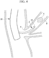
- the manipulating wire 4 which is secured to the gripping portion 20 is advanced, as shown in Fig. 5 , the basket portion 5 is made to protrude from the distal-end opening in the sheath member 2, the folded elastic wires 14 are unfolded, and thus, the basket portion 5 is expanded.
- the basket portion 5 is advanced/retracted and rotated in the bile duct B, and the calculus X in the bile duct B is taken into the basket portion 5.
- the manipulating wire 4 is pulled back, a portion of the basket portion 5 is pulled into the sheath member 2, the basket portion 5 is folded, and thus, the calculus X is squeezed by the elastic wires 14.
- the calculus X is small, it is possible to recover the calculus X by maintaining the calculus X in a captured state by using the folded basket portion 5 and by pulling the calculus X into the channel of the endoscope 30.
- the sheath member 2 which has a high enough compression resistance to endure the compression force for crushing calculus while maintaining a small outer diameter and a high flexibility, it is also possible to crush a large calculus X while maintaining good insertability of the calculus-collecting endoscope treatment tool 1. Therefore, there is an advantage in that it is not necessary to exchange the endoscope treatment tool 1 or the endoscope 30 during operation, and that it is possible to considerably reduce the burden on the patient.
- the sheath member 2 has the resin tube 7 disposed on the inner circumferential side of the metal coil 6, alternatively, as shown in Figs. 6 and 7 , the resin tube 7 may be disposed on the outer circumferential side of the metal coil 6.
- the resin tube 7 disposed on the outer circumferential side of the metal coil 6 to thermally contract, it is possible to secure the resin tube 7 and the metal coil 6 with each other by bringing the resin tube 7 into tight contact with the outer circumferential surface of the metal coil 6 over the entire length thereof.
- the inner diameter of the distal-end member 8 be the same as the inner diameter of the metal coil 6, and that the thickness of the distal-end member 8 in the radial direction satisfy relational expression (1) described below: t 3 > t 1 + t 2 where t3 is the thickness of the distal-end member 8 in the radial direction.
- the distal-end member 8 which is disposed on the distal-end side of the resin tube 7, has an outer diameter that is one size greater than the outer diameter of the resin tube 7, and thus, there is an advantage in that it is possible to protect the distal end of the resin tube 7 by using the distal-end member 8 so that the distal end of the resin tube 7 is not separated from the metal coil 6 during insertion.
- the thickness t1 of the metal coil 6 in the radial direction is made smaller than t2, which is the sum of thicknesses t21 and t22 of the two resin tubes 7 in the radial direction.
- t2 is the sum of thicknesses t21 and t22 of the two resin tubes 7 in the radial direction.
- a strand in which the protrusion 10 on one edge thereof and the depression 11 on the other edge thereof are arc shaped is employed as the strand of the metal coil 6 in this embodiment, the shape thereof is not limited thereto.
- a protrusion 10 in which the center portion of the strand in the radial direction is partially arc shaped may be employed as the protrusion 10.
- the metal coil 6 may be a multithread coil in which a first strand 24 having the protrusions 10 on both edges thereof and a second strand 25 having the depressions 11 on both edges thereof are wound in an alternating manner.
- the basket portion 5 in which the plurality of elastic wires 14 are bundled into a basket shape is employed as the distal-end treating portion, alternatively, as shown in Fig. 12 , a high-frequency snare 27 formed of a loop-shaped metal wire 26 may be employed.
- gripping forceps 32 provided with a pair of forceps pieces 31a and 31b may be employed as the distal-end treating portion.
Landscapes
- Health & Medical Sciences (AREA)
- Surgery (AREA)
- Life Sciences & Earth Sciences (AREA)
- Heart & Thoracic Surgery (AREA)
- Nuclear Medicine, Radiotherapy & Molecular Imaging (AREA)
- Vascular Medicine (AREA)
- Engineering & Computer Science (AREA)
- Biomedical Technology (AREA)
- Orthopedic Medicine & Surgery (AREA)
- Medical Informatics (AREA)
- Molecular Biology (AREA)
- Animal Behavior & Ethology (AREA)
- General Health & Medical Sciences (AREA)
- Public Health (AREA)
- Veterinary Medicine (AREA)
- Surgical Instruments (AREA)
Applications Claiming Priority (2)
| Application Number | Priority Date | Filing Date | Title |
|---|---|---|---|
| JP2015132619 | 2015-07-01 | ||
| PCT/JP2016/062998 WO2017002438A1 (fr) | 2015-07-01 | 2016-04-26 | Instrument de traitement pour endoscope |
Publications (3)
| Publication Number | Publication Date |
|---|---|
| EP3318205A1 true EP3318205A1 (fr) | 2018-05-09 |
| EP3318205A4 EP3318205A4 (fr) | 2019-03-13 |
| EP3318205B1 EP3318205B1 (fr) | 2020-01-29 |
Family
ID=57608491
Family Applications (1)
| Application Number | Title | Priority Date | Filing Date |
|---|---|---|---|
| EP16817548.7A Active EP3318205B1 (fr) | 2015-07-01 | 2016-04-26 | Instrument de traitement pour endoscope |
Country Status (4)
| Country | Link |
|---|---|
| US (1) | US9924960B2 (fr) |
| EP (1) | EP3318205B1 (fr) |
| CN (1) | CN106794021B (fr) |
| WO (1) | WO2017002438A1 (fr) |
Cited By (1)
| Publication number | Priority date | Publication date | Assignee | Title |
|---|---|---|---|---|
| US11504143B2 (en) | 2018-06-28 | 2022-11-22 | Olympus Corporation | Endoscope treatment tool |
Families Citing this family (5)
| Publication number | Priority date | Publication date | Assignee | Title |
|---|---|---|---|---|
| JP6856759B2 (ja) * | 2017-09-06 | 2021-04-14 | オリンパス株式会社 | 高周波処置具および内視鏡システム |
| CN112020333A (zh) * | 2018-04-26 | 2020-12-01 | 奥林巴斯株式会社 | 处置系统和扩张设备 |
| JP7089994B2 (ja) | 2018-09-05 | 2022-06-23 | 朝日インテック株式会社 | 管状体 |
| US11006973B2 (en) * | 2019-01-17 | 2021-05-18 | Olympus Corporation | Method for constricting tissue |
| KR102188957B1 (ko) * | 2019-01-17 | 2020-12-09 | 주식회사 이지엔도서지컬 | 내시경용 바스켓 장치 |
Family Cites Families (45)
| Publication number | Priority date | Publication date | Assignee | Title |
|---|---|---|---|---|
| US3670721A (en) * | 1970-02-05 | 1972-06-20 | Olympus Optical Co | Endoscope |
| JPS5759519A (en) * | 1980-09-30 | 1982-04-09 | Olympus Optical Co | Quide tube for operating and drafting treating tool |
| JPS59231286A (ja) * | 1983-06-10 | 1984-12-25 | カヤバ工業株式会社 | 粒状物などの空気移送用ホ−ス |
| JPS6126508U (ja) * | 1984-07-20 | 1986-02-17 | オリンパス光学工業株式会社 | 内視鏡用処置具 |
| JPS61181453A (ja) * | 1985-02-08 | 1986-08-14 | オリンパス光学工業株式会社 | 結石破砕装置 |
| US5059199A (en) * | 1989-04-12 | 1991-10-22 | Olympus Optical Co., Ltd. | Treating device for endoscopes |
| US5460608A (en) * | 1994-01-25 | 1995-10-24 | Scimed Life Systems, Inc. | Kink free catheter |
| JPH08131550A (ja) * | 1994-11-11 | 1996-05-28 | Nippon Zeon Co Ltd | カテーテル |
| US5762995A (en) * | 1995-01-13 | 1998-06-09 | Fuji Photo Optical Co., Ltd. | Flexible sheathing tube construction, and method for fabrication thereof |
| US6264684B1 (en) * | 1995-03-10 | 2001-07-24 | Impra, Inc., A Subsidiary Of C.R. Bard, Inc. | Helically supported graft |
| US5863366A (en) * | 1995-06-07 | 1999-01-26 | Heartport, Inc. | Method of manufacture of a cannula for a medical device |
| DE19534112A1 (de) * | 1995-09-14 | 1997-03-20 | Wolf Gmbh Richard | Endoskopisches Instrument |
| JP3417778B2 (ja) * | 1997-01-17 | 2003-06-16 | ペンタックス株式会社 | 内視鏡用処置具 |
| US6083152A (en) * | 1999-01-11 | 2000-07-04 | Welch Allyn, Inc. | Endoscopic insertion tube |
| JP3634655B2 (ja) * | 1999-02-09 | 2005-03-30 | ペンタックス株式会社 | 内視鏡用生検鉗子 |
| JP3718372B2 (ja) * | 1999-06-03 | 2005-11-24 | ペンタックス株式会社 | 内視鏡用処置具 |
| US7955340B2 (en) * | 1999-06-25 | 2011-06-07 | Usgi Medical, Inc. | Apparatus and methods for forming and securing gastrointestinal tissue folds |
| JP4418096B2 (ja) * | 2000-09-08 | 2010-02-17 | オリンパス株式会社 | 内視鏡 |
| JP2002224023A (ja) | 2001-02-05 | 2002-08-13 | Asahi Optical Co Ltd | 内視鏡用チャンネルチューブの製造方法 |
| US20040249367A1 (en) * | 2003-01-15 | 2004-12-09 | Usgi Medical Corp. | Endoluminal tool deployment system |
| US8133171B2 (en) * | 2003-06-02 | 2012-03-13 | Karl Storz Endovision, Inc. | Wire spring guide for flexible endoscope |
| US7828790B2 (en) * | 2004-12-03 | 2010-11-09 | Boston Scientific Scimed, Inc. | Selectively flexible catheter and method of use |
| JP4616058B2 (ja) * | 2005-04-14 | 2011-01-19 | オリンパス株式会社 | 内視鏡用アタッチメント、内視鏡用処置具及び内視鏡システム |
| JP2006314715A (ja) | 2005-05-16 | 2006-11-24 | Olympus Medical Systems Corp | 結石破砕装置 |
| JP4880251B2 (ja) * | 2005-06-21 | 2012-02-22 | オリンパスメディカルシステムズ株式会社 | 高周波処置具 |
| US7850623B2 (en) * | 2005-10-27 | 2010-12-14 | Boston Scientific Scimed, Inc. | Elongate medical device with continuous reinforcement member |
| JP4922618B2 (ja) * | 2006-01-13 | 2012-04-25 | オリンパスメディカルシステムズ株式会社 | 内視鏡及び内視鏡システム |
| EP1987789B8 (fr) * | 2006-02-21 | 2016-09-07 | Olympus Corporation | Système d'endoscope et instrument chirurgical |
| US8221390B2 (en) * | 2006-04-20 | 2012-07-17 | Cook Medical Technologies Llc | Medical device delivery system having a sheath with a flared strain relief member operatively coupled by a unidirectional handle |
| US7905877B1 (en) * | 2006-05-12 | 2011-03-15 | Micrus Design Technology, Inc. | Double helix reinforced catheter |
| JP2007307070A (ja) * | 2006-05-17 | 2007-11-29 | Terumo Corp | 医療器具および血管内異物除去用カテーテル |
| US20080172037A1 (en) * | 2006-11-01 | 2008-07-17 | Percutaneous Systems, Inc. | Catheter with adjustable column stability and methods for its use |
| WO2008106549A1 (fr) * | 2007-02-27 | 2008-09-04 | Carnegie Mellon University | Système contrôlant le mouvement d'un dispositif à plusieurs liens |
| JP5228161B2 (ja) * | 2007-03-09 | 2013-07-03 | 富士フイルム株式会社 | 内視鏡の湾曲装置 |
| US8262563B2 (en) * | 2008-07-14 | 2012-09-11 | Ethicon Endo-Surgery, Inc. | Endoscopic translumenal articulatable steerable overtube |
| US8343136B2 (en) * | 2008-08-26 | 2013-01-01 | Cook Medical Technologies Llc | Introducer sheath with encapsulated reinforcing member |
| US8047236B2 (en) * | 2008-09-12 | 2011-11-01 | Boston Scientific Scimed, Inc. | Flexible conduit with locking element |
| US20100228150A1 (en) * | 2009-03-05 | 2010-09-09 | Lake Region Medical, Inc. | Neuro guidewire |
| WO2010132560A1 (fr) * | 2009-05-14 | 2010-11-18 | Vance Products Incorporated, D/B/A/ Cook Urological Incorporated | Gaine d'accès avec déflexion active |
| CN102348420B (zh) * | 2009-06-15 | 2013-05-08 | 奥林巴斯医疗株式会社 | 内窥镜用处理器具 |
| EP2446802B1 (fr) * | 2010-01-29 | 2013-02-13 | Olympus Medical Systems Corp. | Instrument d'insertion, endoscope |
| US9931232B2 (en) * | 2010-10-21 | 2018-04-03 | Boston Scientific Scimed, Inc. | Stent delivery system |
| JP5252606B2 (ja) | 2011-04-13 | 2013-07-31 | オリンパスメディカルシステムズ株式会社 | 内視鏡用処置具 |
| JP5226906B1 (ja) | 2011-09-12 | 2013-07-03 | オリンパスメディカルシステムズ株式会社 | 医療用コイルおよびその製造方法、ならびに医療機器 |
| US9192499B2 (en) * | 2013-03-11 | 2015-11-24 | Cook Medical Technologies Llc | Inner catheter for a self-expanding medical device delivery system with a closed coil wire |
-
2016
- 2016-04-26 WO PCT/JP2016/062998 patent/WO2017002438A1/fr active Application Filing
- 2016-04-26 CN CN201680002387.1A patent/CN106794021B/zh active Active
- 2016-04-26 EP EP16817548.7A patent/EP3318205B1/fr active Active
-
2017
- 2017-02-23 US US15/440,004 patent/US9924960B2/en active Active
Cited By (1)
| Publication number | Priority date | Publication date | Assignee | Title |
|---|---|---|---|---|
| US11504143B2 (en) | 2018-06-28 | 2022-11-22 | Olympus Corporation | Endoscope treatment tool |
Also Published As
| Publication number | Publication date |
|---|---|
| CN106794021A (zh) | 2017-05-31 |
| CN106794021B (zh) | 2019-06-18 |
| WO2017002438A1 (fr) | 2017-01-05 |
| EP3318205B1 (fr) | 2020-01-29 |
| US20170156745A1 (en) | 2017-06-08 |
| EP3318205A4 (fr) | 2019-03-13 |
| US9924960B2 (en) | 2018-03-27 |
Similar Documents
| Publication | Publication Date | Title |
|---|---|---|
| EP3318205B1 (fr) | Instrument de traitement pour endoscope | |
| JP5252606B2 (ja) | 内視鏡用処置具 | |
| JP5226906B1 (ja) | 医療用コイルおよびその製造方法、ならびに医療機器 | |
| EP3081177B1 (fr) | Pince de préhension de type panier | |
| WO2015072394A1 (fr) | Pince de prise du type panier | |
| EP3329858A1 (fr) | Outil d'extraction de tissu et système d'extraction de tissu | |
| EP3275380B1 (fr) | Instrument de traitement pour endoscope | |
| JP2016101315A (ja) | 医療用デバイス | |
| JP2016097050A (ja) | 医療用デバイス | |
| JP6188997B1 (ja) | 内視鏡用処置具 | |
| US11504143B2 (en) | Endoscope treatment tool | |
| JP2017176672A (ja) | 医療用バスケット型処置器具およびその使用方法 | |
| US10932801B2 (en) | Endoscope treatment tool | |
| JP6203034B2 (ja) | 医療用処置具 | |
| JP6038421B1 (ja) | 内視鏡用処置具 | |
| US20210307768A1 (en) | Endoscopic treatment tool | |
| JPH0919439A (ja) | 内視鏡用バスケット型把持具 | |
| JP2014230580A (ja) | バスケット把持具 | |
| JP7144789B2 (ja) | 把持鉗子 | |
| JP6599677B2 (ja) | 内視鏡装置 | |
| JP6734514B2 (ja) | 内視鏡用処置具 | |
| JP6632930B2 (ja) | 結紮装置用クリップユニット及び該クリップユニットの係合方法 | |
| JP2021078830A (ja) | 医療用デバイス | |
| JP2018075279A (ja) | 内視鏡装置用処置具 | |
| JPWO2016056558A1 (ja) | バスケット型把持鉗子 |
Legal Events
| Date | Code | Title | Description |
|---|---|---|---|
| STAA | Information on the status of an ep patent application or granted ep patent |
Free format text: STATUS: THE INTERNATIONAL PUBLICATION HAS BEEN MADE |
|
| PUAI | Public reference made under article 153(3) epc to a published international application that has entered the european phase |
Free format text: ORIGINAL CODE: 0009012 |
|
| STAA | Information on the status of an ep patent application or granted ep patent |
Free format text: STATUS: REQUEST FOR EXAMINATION WAS MADE |
|
| 17P | Request for examination filed |
Effective date: 20180130 |
|
| AK | Designated contracting states |
Kind code of ref document: A1 Designated state(s): AL AT BE BG CH CY CZ DE DK EE ES FI FR GB GR HR HU IE IS IT LI LT LU LV MC MK MT NL NO PL PT RO RS SE SI SK SM TR |
|
| AX | Request for extension of the european patent |
Extension state: BA ME |
|
| DAV | Request for validation of the european patent (deleted) | ||
| DAX | Request for extension of the european patent (deleted) | ||
| A4 | Supplementary search report drawn up and despatched |
Effective date: 20190212 |
|
| RIC1 | Information provided on ipc code assigned before grant |
Ipc: A61B 17/00 20060101ALI20190206BHEP Ipc: A61B 17/29 20060101ALI20190206BHEP Ipc: A61B 17/221 20060101AFI20190206BHEP |
|
| GRAP | Despatch of communication of intention to grant a patent |
Free format text: ORIGINAL CODE: EPIDOSNIGR1 |
|
| STAA | Information on the status of an ep patent application or granted ep patent |
Free format text: STATUS: GRANT OF PATENT IS INTENDED |
|
| RIC1 | Information provided on ipc code assigned before grant |
Ipc: A61B 17/221 20060101AFI20190925BHEP Ipc: A61B 17/00 20060101ALI20190925BHEP Ipc: A61B 17/29 20060101ALI20190925BHEP |
|
| INTG | Intention to grant announced |
Effective date: 20191022 |
|
| GRAS | Grant fee paid |
Free format text: ORIGINAL CODE: EPIDOSNIGR3 |
|
| GRAA | (expected) grant |
Free format text: ORIGINAL CODE: 0009210 |
|
| STAA | Information on the status of an ep patent application or granted ep patent |
Free format text: STATUS: THE PATENT HAS BEEN GRANTED |
|
| AK | Designated contracting states |
Kind code of ref document: B1 Designated state(s): AL AT BE BG CH CY CZ DE DK EE ES FI FR GB GR HR HU IE IS IT LI LT LU LV MC MK MT NL NO PL PT RO RS SE SI SK SM TR |
|
| REG | Reference to a national code |
Ref country code: GB Ref legal event code: FG4D |
|
| REG | Reference to a national code |
Ref country code: CH Ref legal event code: EP |
|
| REG | Reference to a national code |
Ref country code: AT Ref legal event code: REF Ref document number: 1227932 Country of ref document: AT Kind code of ref document: T Effective date: 20200215 |
|
| REG | Reference to a national code |
Ref country code: IE Ref legal event code: FG4D |
|
| REG | Reference to a national code |
Ref country code: DE Ref legal event code: R096 Ref document number: 602016028903 Country of ref document: DE |
|
| REG | Reference to a national code |
Ref country code: NL Ref legal event code: MP Effective date: 20200129 |
|
| PG25 | Lapsed in a contracting state [announced via postgrant information from national office to epo] |
Ref country code: PT Free format text: LAPSE BECAUSE OF FAILURE TO SUBMIT A TRANSLATION OF THE DESCRIPTION OR TO PAY THE FEE WITHIN THE PRESCRIBED TIME-LIMIT Effective date: 20200621 Ref country code: FI Free format text: LAPSE BECAUSE OF FAILURE TO SUBMIT A TRANSLATION OF THE DESCRIPTION OR TO PAY THE FEE WITHIN THE PRESCRIBED TIME-LIMIT Effective date: 20200129 Ref country code: NO Free format text: LAPSE BECAUSE OF FAILURE TO SUBMIT A TRANSLATION OF THE DESCRIPTION OR TO PAY THE FEE WITHIN THE PRESCRIBED TIME-LIMIT Effective date: 20200429 Ref country code: RS Free format text: LAPSE BECAUSE OF FAILURE TO SUBMIT A TRANSLATION OF THE DESCRIPTION OR TO PAY THE FEE WITHIN THE PRESCRIBED TIME-LIMIT Effective date: 20200129 |
|
| REG | Reference to a national code |
Ref country code: LT Ref legal event code: MG4D |
|
| PG25 | Lapsed in a contracting state [announced via postgrant information from national office to epo] |
Ref country code: LV Free format text: LAPSE BECAUSE OF FAILURE TO SUBMIT A TRANSLATION OF THE DESCRIPTION OR TO PAY THE FEE WITHIN THE PRESCRIBED TIME-LIMIT Effective date: 20200129 Ref country code: SE Free format text: LAPSE BECAUSE OF FAILURE TO SUBMIT A TRANSLATION OF THE DESCRIPTION OR TO PAY THE FEE WITHIN THE PRESCRIBED TIME-LIMIT Effective date: 20200129 Ref country code: HR Free format text: LAPSE BECAUSE OF FAILURE TO SUBMIT A TRANSLATION OF THE DESCRIPTION OR TO PAY THE FEE WITHIN THE PRESCRIBED TIME-LIMIT Effective date: 20200129 Ref country code: IS Free format text: LAPSE BECAUSE OF FAILURE TO SUBMIT A TRANSLATION OF THE DESCRIPTION OR TO PAY THE FEE WITHIN THE PRESCRIBED TIME-LIMIT Effective date: 20200529 Ref country code: GR Free format text: LAPSE BECAUSE OF FAILURE TO SUBMIT A TRANSLATION OF THE DESCRIPTION OR TO PAY THE FEE WITHIN THE PRESCRIBED TIME-LIMIT Effective date: 20200430 Ref country code: BG Free format text: LAPSE BECAUSE OF FAILURE TO SUBMIT A TRANSLATION OF THE DESCRIPTION OR TO PAY THE FEE WITHIN THE PRESCRIBED TIME-LIMIT Effective date: 20200429 |
|
| PG25 | Lapsed in a contracting state [announced via postgrant information from national office to epo] |
Ref country code: NL Free format text: LAPSE BECAUSE OF FAILURE TO SUBMIT A TRANSLATION OF THE DESCRIPTION OR TO PAY THE FEE WITHIN THE PRESCRIBED TIME-LIMIT Effective date: 20200129 |
|
| PG25 | Lapsed in a contracting state [announced via postgrant information from national office to epo] |
Ref country code: EE Free format text: LAPSE BECAUSE OF FAILURE TO SUBMIT A TRANSLATION OF THE DESCRIPTION OR TO PAY THE FEE WITHIN THE PRESCRIBED TIME-LIMIT Effective date: 20200129 Ref country code: SM Free format text: LAPSE BECAUSE OF FAILURE TO SUBMIT A TRANSLATION OF THE DESCRIPTION OR TO PAY THE FEE WITHIN THE PRESCRIBED TIME-LIMIT Effective date: 20200129 Ref country code: LT Free format text: LAPSE BECAUSE OF FAILURE TO SUBMIT A TRANSLATION OF THE DESCRIPTION OR TO PAY THE FEE WITHIN THE PRESCRIBED TIME-LIMIT Effective date: 20200129 Ref country code: RO Free format text: LAPSE BECAUSE OF FAILURE TO SUBMIT A TRANSLATION OF THE DESCRIPTION OR TO PAY THE FEE WITHIN THE PRESCRIBED TIME-LIMIT Effective date: 20200129 Ref country code: CZ Free format text: LAPSE BECAUSE OF FAILURE TO SUBMIT A TRANSLATION OF THE DESCRIPTION OR TO PAY THE FEE WITHIN THE PRESCRIBED TIME-LIMIT Effective date: 20200129 Ref country code: ES Free format text: LAPSE BECAUSE OF FAILURE TO SUBMIT A TRANSLATION OF THE DESCRIPTION OR TO PAY THE FEE WITHIN THE PRESCRIBED TIME-LIMIT Effective date: 20200129 Ref country code: DK Free format text: LAPSE BECAUSE OF FAILURE TO SUBMIT A TRANSLATION OF THE DESCRIPTION OR TO PAY THE FEE WITHIN THE PRESCRIBED TIME-LIMIT Effective date: 20200129 Ref country code: SK Free format text: LAPSE BECAUSE OF FAILURE TO SUBMIT A TRANSLATION OF THE DESCRIPTION OR TO PAY THE FEE WITHIN THE PRESCRIBED TIME-LIMIT Effective date: 20200129 |
|
| REG | Reference to a national code |
Ref country code: DE Ref legal event code: R097 Ref document number: 602016028903 Country of ref document: DE |
|
| REG | Reference to a national code |
Ref country code: AT Ref legal event code: MK05 Ref document number: 1227932 Country of ref document: AT Kind code of ref document: T Effective date: 20200129 |
|
| PG25 | Lapsed in a contracting state [announced via postgrant information from national office to epo] |
Ref country code: MC Free format text: LAPSE BECAUSE OF FAILURE TO SUBMIT A TRANSLATION OF THE DESCRIPTION OR TO PAY THE FEE WITHIN THE PRESCRIBED TIME-LIMIT Effective date: 20200129 |
|
| REG | Reference to a national code |
Ref country code: CH Ref legal event code: PL |
|
| PLBE | No opposition filed within time limit |
Free format text: ORIGINAL CODE: 0009261 |
|
| STAA | Information on the status of an ep patent application or granted ep patent |
Free format text: STATUS: NO OPPOSITION FILED WITHIN TIME LIMIT |
|
| 26N | No opposition filed |
Effective date: 20201030 |
|
| PG25 | Lapsed in a contracting state [announced via postgrant information from national office to epo] |
Ref country code: LI Free format text: LAPSE BECAUSE OF NON-PAYMENT OF DUE FEES Effective date: 20200430 Ref country code: LU Free format text: LAPSE BECAUSE OF NON-PAYMENT OF DUE FEES Effective date: 20200426 Ref country code: CH Free format text: LAPSE BECAUSE OF NON-PAYMENT OF DUE FEES Effective date: 20200430 Ref country code: FR Free format text: LAPSE BECAUSE OF NON-PAYMENT OF DUE FEES Effective date: 20200430 Ref country code: AT Free format text: LAPSE BECAUSE OF FAILURE TO SUBMIT A TRANSLATION OF THE DESCRIPTION OR TO PAY THE FEE WITHIN THE PRESCRIBED TIME-LIMIT Effective date: 20200129 Ref country code: IT Free format text: LAPSE BECAUSE OF FAILURE TO SUBMIT A TRANSLATION OF THE DESCRIPTION OR TO PAY THE FEE WITHIN THE PRESCRIBED TIME-LIMIT Effective date: 20200129 |
|
| REG | Reference to a national code |
Ref country code: BE Ref legal event code: MM Effective date: 20200430 |
|
| PG25 | Lapsed in a contracting state [announced via postgrant information from national office to epo] |
Ref country code: BE Free format text: LAPSE BECAUSE OF NON-PAYMENT OF DUE FEES Effective date: 20200430 Ref country code: PL Free format text: LAPSE BECAUSE OF FAILURE TO SUBMIT A TRANSLATION OF THE DESCRIPTION OR TO PAY THE FEE WITHIN THE PRESCRIBED TIME-LIMIT Effective date: 20200129 Ref country code: SI Free format text: LAPSE BECAUSE OF FAILURE TO SUBMIT A TRANSLATION OF THE DESCRIPTION OR TO PAY THE FEE WITHIN THE PRESCRIBED TIME-LIMIT Effective date: 20200129 |
|
| GBPC | Gb: european patent ceased through non-payment of renewal fee |
Effective date: 20200429 |
|
| PG25 | Lapsed in a contracting state [announced via postgrant information from national office to epo] |
Ref country code: GB Free format text: LAPSE BECAUSE OF NON-PAYMENT OF DUE FEES Effective date: 20200429 Ref country code: IE Free format text: LAPSE BECAUSE OF NON-PAYMENT OF DUE FEES Effective date: 20200426 |
|
| PG25 | Lapsed in a contracting state [announced via postgrant information from national office to epo] |
Ref country code: TR Free format text: LAPSE BECAUSE OF FAILURE TO SUBMIT A TRANSLATION OF THE DESCRIPTION OR TO PAY THE FEE WITHIN THE PRESCRIBED TIME-LIMIT Effective date: 20200129 Ref country code: MT Free format text: LAPSE BECAUSE OF FAILURE TO SUBMIT A TRANSLATION OF THE DESCRIPTION OR TO PAY THE FEE WITHIN THE PRESCRIBED TIME-LIMIT Effective date: 20200129 Ref country code: CY Free format text: LAPSE BECAUSE OF FAILURE TO SUBMIT A TRANSLATION OF THE DESCRIPTION OR TO PAY THE FEE WITHIN THE PRESCRIBED TIME-LIMIT Effective date: 20200129 |
|
| PG25 | Lapsed in a contracting state [announced via postgrant information from national office to epo] |
Ref country code: MK Free format text: LAPSE BECAUSE OF FAILURE TO SUBMIT A TRANSLATION OF THE DESCRIPTION OR TO PAY THE FEE WITHIN THE PRESCRIBED TIME-LIMIT Effective date: 20200129 Ref country code: AL Free format text: LAPSE BECAUSE OF FAILURE TO SUBMIT A TRANSLATION OF THE DESCRIPTION OR TO PAY THE FEE WITHIN THE PRESCRIBED TIME-LIMIT Effective date: 20200129 |
|
| P01 | Opt-out of the competence of the unified patent court (upc) registered |
Effective date: 20230528 |
|
| PGFP | Annual fee paid to national office [announced via postgrant information from national office to epo] |
Ref country code: DE Payment date: 20230420 Year of fee payment: 8 |