EP3317023B1 - Applikationsgerät, insbesondere rotationszerstäuber - Google Patents
Applikationsgerät, insbesondere rotationszerstäuber Download PDFInfo
- Publication number
- EP3317023B1 EP3317023B1 EP16735575.9A EP16735575A EP3317023B1 EP 3317023 B1 EP3317023 B1 EP 3317023B1 EP 16735575 A EP16735575 A EP 16735575A EP 3317023 B1 EP3317023 B1 EP 3317023B1
- Authority
- EP
- European Patent Office
- Prior art keywords
- valve
- coating agent
- line
- needle
- application device
- Prior art date
- Legal status (The legal status is an assumption and is not a legal conclusion. Google has not performed a legal analysis and makes no representation as to the accuracy of the status listed.)
- Active
Links
- 239000011248 coating agent Substances 0.000 claims description 139
- 239000003973 paint Substances 0.000 claims description 126
- 239000002904 solvent Substances 0.000 claims description 64
- 239000012528 membrane Substances 0.000 claims description 43
- 238000007789 sealing Methods 0.000 claims description 41
- 238000011144 upstream manufacturing Methods 0.000 claims description 25
- 239000012530 fluid Substances 0.000 claims description 20
- 238000011010 flushing procedure Methods 0.000 claims description 14
- 239000003795 chemical substances by application Substances 0.000 claims description 8
- 239000006260 foam Substances 0.000 claims description 8
- 239000007788 liquid Substances 0.000 claims description 6
- 230000002093 peripheral effect Effects 0.000 claims description 3
- 238000013016 damping Methods 0.000 claims description 2
- 238000007599 discharging Methods 0.000 claims description 2
- 230000003068 static effect Effects 0.000 claims description 2
- 239000004848 polyfunctional curative Substances 0.000 description 60
- 239000004922 lacquer Substances 0.000 description 19
- 239000000203 mixture Substances 0.000 description 7
- 230000009172 bursting Effects 0.000 description 4
- 238000006073 displacement reaction Methods 0.000 description 4
- 239000000463 material Substances 0.000 description 4
- 239000003599 detergent Substances 0.000 description 3
- 238000000034 method Methods 0.000 description 3
- 238000010422 painting Methods 0.000 description 3
- 230000008569 process Effects 0.000 description 3
- 229920006169 Perfluoroelastomer Polymers 0.000 description 2
- RTAQQCXQSZGOHL-UHFFFAOYSA-N Titanium Chemical compound [Ti] RTAQQCXQSZGOHL-UHFFFAOYSA-N 0.000 description 2
- 230000009286 beneficial effect Effects 0.000 description 2
- 238000004140 cleaning Methods 0.000 description 2
- 230000006835 compression Effects 0.000 description 2
- 238000007906 compression Methods 0.000 description 2
- 238000010276 construction Methods 0.000 description 2
- 238000010586 diagram Methods 0.000 description 2
- 229920001971 elastomer Polymers 0.000 description 2
- 230000012447 hatching Effects 0.000 description 2
- 239000012948 isocyanate Substances 0.000 description 2
- 150000002513 isocyanates Chemical class 0.000 description 2
- 230000004048 modification Effects 0.000 description 2
- 238000012986 modification Methods 0.000 description 2
- 230000009467 reduction Effects 0.000 description 2
- 229910052719 titanium Inorganic materials 0.000 description 2
- 239000010936 titanium Substances 0.000 description 2
- XLYOFNOQVPJJNP-UHFFFAOYSA-N water Substances O XLYOFNOQVPJJNP-UHFFFAOYSA-N 0.000 description 2
- 238000006424 Flood reaction Methods 0.000 description 1
- 206010021703 Indifference Diseases 0.000 description 1
- 229910001069 Ti alloy Inorganic materials 0.000 description 1
- 239000000853 adhesive Substances 0.000 description 1
- 230000001070 adhesive effect Effects 0.000 description 1
- 230000008901 benefit Effects 0.000 description 1
- 230000008859 change Effects 0.000 description 1
- 238000006243 chemical reaction Methods 0.000 description 1
- 238000000576 coating method Methods 0.000 description 1
- 230000002950 deficient Effects 0.000 description 1
- 238000011161 development Methods 0.000 description 1
- 230000018109 developmental process Effects 0.000 description 1
- 239000013013 elastic material Substances 0.000 description 1
- 238000000227 grinding Methods 0.000 description 1
- 239000011810 insulating material Substances 0.000 description 1
- 230000007257 malfunction Effects 0.000 description 1
- 230000008439 repair process Effects 0.000 description 1
- 239000000565 sealant Substances 0.000 description 1
- 239000007921 spray Substances 0.000 description 1
Images


Classifications
-
- B—PERFORMING OPERATIONS; TRANSPORTING
- B05—SPRAYING OR ATOMISING IN GENERAL; APPLYING FLUENT MATERIALS TO SURFACES, IN GENERAL
- B05B—SPRAYING APPARATUS; ATOMISING APPARATUS; NOZZLES
- B05B12/00—Arrangements for controlling delivery; Arrangements for controlling the spray area
- B05B12/08—Arrangements for controlling delivery; Arrangements for controlling the spray area responsive to condition of liquid or other fluent material to be discharged, of ambient medium or of target ; responsive to condition of spray devices or of supply means, e.g. pipes, pumps or their drive means
- B05B12/085—Arrangements for controlling delivery; Arrangements for controlling the spray area responsive to condition of liquid or other fluent material to be discharged, of ambient medium or of target ; responsive to condition of spray devices or of supply means, e.g. pipes, pumps or their drive means responsive to flow or pressure of liquid or other fluent material to be discharged
- B05B12/087—Flow or presssure regulators, i.e. non-electric unitary devices comprising a sensing element, e.g. a piston or a membrane, and a controlling element, e.g. a valve
-
- B—PERFORMING OPERATIONS; TRANSPORTING
- B05—SPRAYING OR ATOMISING IN GENERAL; APPLYING FLUENT MATERIALS TO SURFACES, IN GENERAL
- B05B—SPRAYING APPARATUS; ATOMISING APPARATUS; NOZZLES
- B05B7/00—Spraying apparatus for discharge of liquids or other fluent materials from two or more sources, e.g. of liquid and air, of powder and gas
- B05B7/02—Spray pistols; Apparatus for discharge
- B05B7/04—Spray pistols; Apparatus for discharge with arrangements for mixing liquids or other fluent materials before discharge
- B05B7/0408—Spray pistols; Apparatus for discharge with arrangements for mixing liquids or other fluent materials before discharge with arrangements for mixing two or more liquids
-
- B—PERFORMING OPERATIONS; TRANSPORTING
- B05—SPRAYING OR ATOMISING IN GENERAL; APPLYING FLUENT MATERIALS TO SURFACES, IN GENERAL
- B05B—SPRAYING APPARATUS; ATOMISING APPARATUS; NOZZLES
- B05B1/00—Nozzles, spray heads or other outlets, with or without auxiliary devices such as valves, heating means
- B05B1/30—Nozzles, spray heads or other outlets, with or without auxiliary devices such as valves, heating means designed to control volume of flow, e.g. with adjustable passages
- B05B1/3006—Nozzles, spray heads or other outlets, with or without auxiliary devices such as valves, heating means designed to control volume of flow, e.g. with adjustable passages the controlling element being actuated by the pressure of the fluid to be sprayed
-
- B—PERFORMING OPERATIONS; TRANSPORTING
- B05—SPRAYING OR ATOMISING IN GENERAL; APPLYING FLUENT MATERIALS TO SURFACES, IN GENERAL
- B05B—SPRAYING APPARATUS; ATOMISING APPARATUS; NOZZLES
- B05B1/00—Nozzles, spray heads or other outlets, with or without auxiliary devices such as valves, heating means
- B05B1/30—Nozzles, spray heads or other outlets, with or without auxiliary devices such as valves, heating means designed to control volume of flow, e.g. with adjustable passages
- B05B1/3033—Nozzles, spray heads or other outlets, with or without auxiliary devices such as valves, heating means designed to control volume of flow, e.g. with adjustable passages the control being effected by relative coaxial longitudinal movement of the controlling element and the spray head
- B05B1/304—Nozzles, spray heads or other outlets, with or without auxiliary devices such as valves, heating means designed to control volume of flow, e.g. with adjustable passages the control being effected by relative coaxial longitudinal movement of the controlling element and the spray head the controlling element being a lift valve
- B05B1/3046—Nozzles, spray heads or other outlets, with or without auxiliary devices such as valves, heating means designed to control volume of flow, e.g. with adjustable passages the control being effected by relative coaxial longitudinal movement of the controlling element and the spray head the controlling element being a lift valve the valve element, e.g. a needle, co-operating with a valve seat located downstream of the valve element and its actuating means, generally in the proximity of the outlet orifice
- B05B1/306—Nozzles, spray heads or other outlets, with or without auxiliary devices such as valves, heating means designed to control volume of flow, e.g. with adjustable passages the control being effected by relative coaxial longitudinal movement of the controlling element and the spray head the controlling element being a lift valve the valve element, e.g. a needle, co-operating with a valve seat located downstream of the valve element and its actuating means, generally in the proximity of the outlet orifice the actuating means being a fluid
-
- B—PERFORMING OPERATIONS; TRANSPORTING
- B05—SPRAYING OR ATOMISING IN GENERAL; APPLYING FLUENT MATERIALS TO SURFACES, IN GENERAL
- B05B—SPRAYING APPARATUS; ATOMISING APPARATUS; NOZZLES
- B05B15/00—Details of spraying plant or spraying apparatus not otherwise provided for; Accessories
- B05B15/50—Arrangements for cleaning; Arrangements for preventing deposits, drying-out or blockage; Arrangements for detecting improper discharge caused by the presence of foreign matter
- B05B15/55—Arrangements for cleaning; Arrangements for preventing deposits, drying-out or blockage; Arrangements for detecting improper discharge caused by the presence of foreign matter using cleaning fluids
-
- B—PERFORMING OPERATIONS; TRANSPORTING
- B05—SPRAYING OR ATOMISING IN GENERAL; APPLYING FLUENT MATERIALS TO SURFACES, IN GENERAL
- B05B—SPRAYING APPARATUS; ATOMISING APPARATUS; NOZZLES
- B05B15/00—Details of spraying plant or spraying apparatus not otherwise provided for; Accessories
- B05B15/14—Arrangements for preventing or controlling structural damage to spraying apparatus or its outlets, e.g. for breaking at desired places; Arrangements for handling or replacing damaged parts
-
- B—PERFORMING OPERATIONS; TRANSPORTING
- B05—SPRAYING OR ATOMISING IN GENERAL; APPLYING FLUENT MATERIALS TO SURFACES, IN GENERAL
- B05B—SPRAYING APPARATUS; ATOMISING APPARATUS; NOZZLES
- B05B15/00—Details of spraying plant or spraying apparatus not otherwise provided for; Accessories
- B05B15/50—Arrangements for cleaning; Arrangements for preventing deposits, drying-out or blockage; Arrangements for detecting improper discharge caused by the presence of foreign matter
- B05B15/58—Arrangements for cleaning; Arrangements for preventing deposits, drying-out or blockage; Arrangements for detecting improper discharge caused by the presence of foreign matter preventing deposits, drying-out or blockage by recirculating the fluid to be sprayed from upstream of the discharge opening back to the supplying means
-
- B—PERFORMING OPERATIONS; TRANSPORTING
- B05—SPRAYING OR ATOMISING IN GENERAL; APPLYING FLUENT MATERIALS TO SURFACES, IN GENERAL
- B05B—SPRAYING APPARATUS; ATOMISING APPARATUS; NOZZLES
- B05B3/00—Spraying or sprinkling apparatus with moving outlet elements or moving deflecting elements
- B05B3/02—Spraying or sprinkling apparatus with moving outlet elements or moving deflecting elements with rotating elements
- B05B3/10—Spraying or sprinkling apparatus with moving outlet elements or moving deflecting elements with rotating elements discharging over substantially the whole periphery of the rotating member, i.e. the spraying being effected by centrifugal forces
- B05B3/1007—Spraying or sprinkling apparatus with moving outlet elements or moving deflecting elements with rotating elements discharging over substantially the whole periphery of the rotating member, i.e. the spraying being effected by centrifugal forces characterised by the rotating member
- B05B3/1014—Spraying or sprinkling apparatus with moving outlet elements or moving deflecting elements with rotating elements discharging over substantially the whole periphery of the rotating member, i.e. the spraying being effected by centrifugal forces characterised by the rotating member with a spraying edge, e.g. like a cup or a bell
Definitions
- the invention relates to an application device, in particular a rotary atomizer, for applying a coating agent.
- Two-component paints (2K paints) are known from the prior art, which consist of two components, namely a hardener (e.g. isocyanate) and a base paint.
- a hardener e.g. isocyanate
- a base paint e.g. isocyanate
- needle valves that have a displaceable valve needle are usually used as shut-off valves.
- the valve needle runs through a valve chamber which is filled with the 2K paint during operation, the valve chamber being sealed off from the valve drive acting on the valve needle by a sealing ring.
- the inner side of the sealing ring rubs against the outer surface of the valve needle and its outer circumference rests against the inner wall of the valve chamber.
- the problem here is the fact that the hardener (e.g. isocyanate) usually reacts with water and then hardens. Even the smallest amounts of water are sufficient to start the curing process, so that, for example, normal humidity already leads to curing. This is problematic because the 2K paint or the hardener used is very capable of creeping and has low viscosity and can therefore infiltrate the sealing ring around the valve needle so that the 2K paint or the hardener can escape from the paint-filled valve chamber into the area of the valve drive.
- the hardener e.g. isocyanate
- the cured 2K paint can stick the valve needle in the valve seat.
- the 2K paint can adhere to the valve needle and then damage the surrounding sealing ring when it has hardened, which leads to a leak.
- hardened deposits in the valve seat can lead to the valve no longer closing. Hardening can also cause the valve to close more slowly.
- a valve failure is particularly problematic if the valve can no longer open, as an overpressure disturbance can then occur upstream in front of the valve, which in extreme cases can lead to the supply hoses bursting, which can cause 2K paint or hardener to escape results in considerable downtimes for cleaning and repair work.
- EP 2 990 124 A1 a compressed air operated coating agent valve which controls the coating agent flow to an application device.
- the actuation of the coating agent valve takes place here exclusively by compressed air and the coating agent valve is structurally separate from the application device.
- the invention is therefore based on the object of providing a correspondingly improved application device which prevents supply lines from bursting in the event of a valve failure (i.e. a valve sticking).
- a valve failure i.e. a valve sticking
- the application device according to the invention e.g. rotary atomizer
- a first coating agent connection via which a first coating agent can be supplied such as a base paint of a two-component paint (2K paint).
- application device used in the context of the invention is not limited to the preferred embodiment of a rotary atomizer, wherein such rotary atomizers can have a rotating bell plate or a rotating disc as the spray element.
- Other possible exemplary embodiments for application devices according to the invention are air atomizers, strip atomizers (e.g. according to FIG DE 10 2013 002 412 A1 ), Hand guns, disc atomizers, airless atomizers, airmix atomizers and ultrasonic atomizers, to name a few examples.
- the invention is not limited to paints or paint components with regard to the applied coating agent. Rather, the coating agent can also be other fluids, such as sealant, insulating material or adhesive, to name just a few examples.
- the invention is not limited to one-component coating agents or two-component coating agents, but can also be used with multicomponent coating agents which, for example, can have three components.
- the application device according to the invention has a first strand of coating agent, which extends from the first coating agent connection in the application device and guides the first coating agent.
- a controllable first valve which controls the flow of the first coating agent through the first strand of coating agent is arranged in this first strand of coating agent, this first valve being controllable by a first control signal.
- the control signal can be, for example, an electrical control signal or a pneumatic control signal, but the invention with regard to the control of the valves is not limited to these examples.
- the application device is now distinguished from the prior art in that a first pressure relief valve actuated by its own medium is arranged in the first line of coating agent, which opens automatically to avoid an excess pressure disruption when the pressure upstream of the first pressure relief valve exceeds a certain maximum pressure. If there is an overpressure disturbance in the first coating agent strand because a valve in the first coating agent strand fails and no longer opens, the supply lines are prevented from bursting because the first overpressure valve then opens automatically.
- the first pressure relief valve is therefore a pressure relief valve actuated by its own medium, which opens or closes as a function of the fluid pressure applied on the inlet side.
- All fluid lines in the application device that are at risk of overpressure are preferably protected by overpressure valves of this type in order to enable a pressure reduction in the event of overpressure disturbances.
- This can include all fluid lines in the application device, for example for base paint, hardener, ready-mixed two-component paint, one-component paint, solvent (detergent).
- the first pressure relief valve is formed by the controllable first valve.
- the first valve has two functions. On the one hand, the first valve enables the fluid flow through the first strand of coating agent to be controlled. On the other hand, the first valve also functions as an overpressure valve and opens automatically (actuated by its own medium) when the pressure applied on the inlet side exceeds a certain maximum pressure.
- the first strand of coating agent leads to an application element which applies the first coating agent.
- this application element can be a bell cup or a paint nozzle in a bell cup, but the invention is not limited to this example with regard to the type of application element.
- a first main valve is arranged in the first line of coating agent between the first pressure relief valve and the application element, which valve either shuts off or releases the fluid flow in the first line of coating agent.
- the first main valve is preferably designed as a main needle valve and has a displaceable valve needle which optionally releases or blocks a valve seat.
- the application device has a second coating agent connection in order to supply a second coating agent, such as, for example, a hardener of the 2K paint.
- a second coating agent line then emanates from this second coating agent connection, with a second pressure relief valve being arranged in the second coating agent line, which is also actuated by its own medium and opens automatically when the pressure upstream of the first pressure relief valve exceeds a certain maximum pressure.
- the second strand of coating agent preferably opens upstream in front of the first main valve into the first strand of coating agent, which enables the base paint to be mixed with the hardener.
- a mixer is therefore preferably arranged between the junction of the second coating agent strand and the first main valve, which mixer mixes the base lacquer with the hardener to form the 2K lacquer.
- the mixer is preferably designed as a static mixer, for example as a grid mixer or as a helical mixer.
- Such mixers are for example DE 10 2010 019 771 A1 known, so that the content of this publication is to be included in the present description with regard to the structure and mode of operation of the mixer in full.
- the application device preferably has a first return connection in order to return fluids (e.g. residues of the base paint) to a first return.
- a first return line branches off from the first coating agent line upstream in front of the first pressure relief valve and opens into the first return connection.
- a third pressure relief valve is preferably arranged in the first return line, which is also actuated by its own medium and opens automatically when the pressure in the first return line upstream of the third pressure relief valve exceeds a certain maximum value.
- the application device preferably has a first solvent connection in order to supply a first solvent, the first solvent preferably being provided for the base paint.
- a first solvent line preferably emanates from this first solvent connection, the first solvent line preferably opening into the first coating agent line, namely between the first pressure relief valve and the first main valve.
- a first solvent valve which is controllable and which enables or blocks the flow of solvent, is preferably arranged in the first solvent line.
- the application device preferably has a pulsed air connection in order to supply pulsed air for cleaning purposes, which is known per se from the prior art.
- a pulsed air line preferably emanates from this pulsed air connection and opens into the first coating agent line, namely preferably between the first pressure relief valve and the first main valve, wherein a pulsed air valve can be arranged in the pulsed air line to control the pulsed air.
- the application device preferably comprises a second solvent connection for supplying a second solvent, which is preferably provided for the hardener is.
- a second solvent line then preferably emanates from this second solvent connection, which opens into the first coating agent line between the first pressure relief valve and the first main valve, a second solvent valve preferably being arranged in the second solvent line.
- This second solvent valve is preferably controllable in order to selectively enable or block the flow of solvent.
- the first coating agent connection preferably also emanates a third coating agent strand, wherein a second main valve can be arranged in the third coating agent strand, in particular in the form of a main needle valve, which is known per se from the prior art and is therefore not described in more detail must become.
- the first main valve and the second main valve are then preferably brought together on the outlet side and lead to the application element (e.g. bell plate).
- the application device can be used either to apply a one-component paint or to apply a two-component paint.
- the application device preferably has a second return connection in order to return fluids (e.g. pulsed air, paint foam) to a second return.
- a second return line which opens into the second return connection, then branches off from the third coating agent line, preferably upstream of the second main valve, a return valve preferably being arranged in this second return line.
- This return valve is preferably operated by its own medium, with the return valve preferably, due to its construction, between liquid coating agent at the inlet on the one hand and compressed air or Foam at the entrance on the other hand is different.
- the return valve opens automatically when compressed air or foam is present at the inlet of the return valve. In contrast, the return valve closes when liquid coating agent is present at the inlet of the return valve.
- the return valve can therefore also be referred to as a paint stop valve, as it closes automatically when liquid paint is present at the inlet of the return valve instead of compressed air or foam.
- the structure and function of such a paint stop valve is detailed in DE 10 2009 020 064 A1 so that the content of this publication can be fully attributed to the present description with regard to the structure and mode of operation of the return valve (paint stop valve).
- the application device preferably has at least one short flush connection in order to supply a flushing agent for a short flush of the application device.
- At least one short rinse line then emanates from the short rinse connection, which can guide the rinsing agent to the application element while bypassing the coating agent lines.
- a controllable short flush valve is preferably arranged in the short flush line, which optionally enables or blocks the flow of the flushing agent.
- the overpressure valves in the open state preferably have a pressure surge damping function, so that pressure surges arriving on the inlet side are only passed on in a damped manner on the outlet side.
- This can be achieved, for example, in that the pressure relief valves are designed as diaphragm valves, which will be described in detail below.
- the invention also includes the technical teaching that the pressure relief valve is a special needle valve.
- the needle valve according to the invention initially has, in accordance with the prior art, a valve seat and a displaceable valve needle with a needle shaft and a needle head.
- the valve needle can be displaced between a closed position and an open position. In the closed position, the needle head of the valve needle closes the valve seat and thereby blocks the flow of fluid. In the open position, on the other hand, the valve needle is lifted from the needle head and thereby releases the fluid flow.
- different intermediate positions of the valve needle can be continuously set between the open position and the closed position in order to control the fluid flow not only qualitatively (open / closed) but also quantitatively, i.e. H. with an adjustable flow resistance.
- the needle valve controls the fluid flow only qualitatively in that the fluid flow is either released or blocked.
- the invention now provides that the valve space surrounding the valve needle and filled with media during operation is sealed by a flexible membrane which surrounds the valve needle in a ring-shaped and sealing manner upstream of the needle head.
- the flexible membrane reliably prevents the coating agent (e.g. hardener) from escaping from the media-filled valve chamber in the direction of the valve drive and from hardening there.
- the valve needle is arranged displaceably in the valve chamber, the valve chamber being cylindrical at least in sections.
- the center of the membrane is then preferably in sealing contact with the needle shaft of the valve needle and is attached to the needle shaft of the valve needle. This means that the The membrane does not rub against the valve needle, but participates in the displacement movement of the valve needle between the open position and the closed position. This means that a displacement of the valve needle leads to a corresponding axial deflection of the membrane.
- an axial deflection of the membrane for example due to one-sided application of pressure to the membrane, also leads to a corresponding displacement of the valve needle.
- the membrane is attached to the inner wall of the valve chamber in a sealing manner.
- the diaphragm thus enables an axial stroke in the center which is at least as large as the axial distance between the closed position and the open position of the valve needle, so that the diaphragm does not hinder the movement of the valve needle.
- the needle valve has a valve drive for moving the valve needle, wherein the valve drive can be designed, for example, as a pneumatic valve drive with a piston, which is known from the prior art and therefore does not need to be described in more detail.
- the needle valve according to the invention preferably has a coating agent inlet in order to supply the coating agent (e.g. 2K paint or hardener), the coating agent inlet preferably opening into the valve chamber on the side of the membrane facing away from the valve drive, so that the membrane is opposite the valve drive seals the valve chamber filled with the coating agent.
- the coating agent e.g. 2K paint or hardener
- the needle valve according to the invention preferably contains a coating agent outlet in order to dispense the coating agent, the coating agent outlet preferably opening into the valve seat, so that the coating agent in the open position of the valve needle can flow through the valve seat to the coating agent outlet.
- the needle valve according to the invention can have a valve drive in order to move the valve needle.
- this valve drive comprises a displaceable piston which acts on the valve needle in order to move the valve needle.
- the piston is preferably driven pneumatically.
- the needle valve preferably has a control air inlet in order to supply control air, the control air acting on the piston in order to move the piston and thus also the valve needle.
- the needle valve according to the invention preferably comprises a valve spring which acts with a spring force on the piston or the valve needle.
- the valve spring on the one hand and the control air on the other hand preferably act in opposite directions.
- the spring force of the valve spring is preferably at least 20 N, 40 N or at least 80 N and / or at most 400 N, 200 N or 100 N, which preferably applies to both the closed position and the open position of the valve spring.
- valve spring presses the valve needle in the direction of the closed position
- control air presses the valve needle via the piston in the direction of the open position
- the valve spring and the needle head are preferably arranged on opposite sides of the piston.
- the piston is preferably a has a relatively large piston diameter in order to generate the greatest possible opening force when the valve needle is moved into the open position. It must be taken into account that the opening force depends on the effective piston area and thus also on the piston diameter and the pneumatic pressure of the control air.
- the piston therefore preferably has a piston diameter of at least 5 mm, 10 mm, 15 mm, 20 mm, 25 mm or even 32 mm.
- the piston diameter is preferably so large that a sufficiently large opening force can be achieved with a conventional control air pressure of less than 6 bar. This makes sense because the usual 6 bar compressed air networks are usually available in painting systems, which can then also be used to control the needle valve according to the invention. In this way, there is no need for a separate compressed air network for controlling the needle valve.
- valve spring presses the valve needle preferably in the direction of the closed position, with a certain closing force.
- the pneumatic valve drive pushes the valve needle with a certain opening force in the direction of the open position when it is pneumatically activated.
- the opening force of the pneumatic valve drive should be a certain excess opening force greater than the closing force in order to be able to reliably open the needle valve when the needle head adheres to the valve seat.
- the needle valve is therefore preferably designed so that the excess opening force is greater than 20 N, 40 N, 60 N, 80 N, 100 N, 120 N, 130 N or even 180 N.
- the needle valve according to the invention therefore has an overpressure function which, when a certain opening pressure at the coating agent inlet is exceeded, leads to the valve opening automatically.
- the coating agent located in the valve chamber presses against the membrane, whereby the membrane and thus also the valve needle are pressed from the closed position into the open position when the coating agent pressure is high enough to overcome the opposing force of the valve spring.
- the membrane therefore preferably has a membrane diameter of at least 3 mm, 6 mm or 9 mm and / or at most 40 mm, 20 mm or 11 mm.
- the opening pressure of the coating agent at the coating agent inlet is then preferably at least 8 bar, 10 bar, 12 bar, 14 bar or at least 38 bar and / or at most 38 bar, 22 bar, 18 bar or 16 bar.
- the closing force of the spring must therefore be adapted to the desired opening pressure and the effective cross section of the membrane so that the coating agent pressure in the valve chamber pushes the membrane and thus also the valve needle from the closed position into the open position when the desired opening pressure is exceeded.
- valve seat preferably narrows with a specific seat angle in the direction of flow, just as the needle head also narrows preferably with a specific head angle in the direction of flow.
- the seat angle is essentially equal to the head angle.
- the seat angle can be in the range of 35 ° -50 °, and the head angle is also preferably in the range of 35 ° -50 °, which ensures an optimal seal.
- a larger head angle improves the flow of the medium in the needle valves according to the invention with an additional membrane, which are equipped with low needle lifts (approx. 1.5 mm instead of 3 mm for conventional needle valves).
- an additional sealing element is inserted into the needle head of the valve needle in order to seal the valve seat in the closed position.
- This additional sealing element can consist of a different material than the needle head of the valve needle, an elastic material preferably being used, such as FFKM (perfluorinated rubber).
- FFKM perfluorinated rubber
- the additional sealing element can be vulcanized onto the needle head.
- the sealing element is inserted into the needle head, for example in an annular groove in the needle head.
- the needle head itself can consist of titanium or a titanium alloy, for example, so that the needle head is resistant to chemically aggressive hardeners of 2K paints.
- the needle head and the valve seat preferably taper essentially conically in the direction of flow.
- the needle head can have an annular groove into which the sealing element briefly mentioned above can be inserted.
- the sealing element in the needle head is only subjected to pressure until the valve needle rests with its stop on the valve seat. In this way, the compression of the sealing element in the needle head is limited when the valve is closed, which is beneficial to the service life of the sealing element.
- this stop is formed by an annular, circumferential support surface which is located in the conical jacket surface of the needle head upstream in front of the sealing element.
- the problem here can be that the sealing element seals the area of the needle head downstream behind the sealing element, so that this area cannot be reached by the detergent during a flushing process.
- the support surface has at least one axially extending flushing groove through which flushing agent can enter in the axial direction from the valve chamber into the area downstream behind the sealing element.
- a flushing groove can have a groove width of 1 mm to 2 mm.
- the flexible membrane sealing the valve chamber replaces the sealing ring that is present in conventional needle valves.
- a conventional sealing ring which is used for the valve needle surrounds ring-shaped and rests on the surface of the valve needle with a drag.
- the needle shaft of the valve needle preferably has a diameter which can be in the range from 2 mm to 10 mm, 3 mm to 6 mm or 4 mm to 5 mm.
- the maximum needle lift of the valve needle is preferably less than 3 mm, 2.5 mm, 2 mm or even less than 1.6 mm.
- a first variant of the invention has already been described above in which two strands of coating agent run within the application device.
- One strand of coating agent is reserved for a hardener for a two-component paint.
- the other strand of coating agent can optionally be used for an associated master paint of the two-component paint or for a one-component paint.
- three strands of coating agent run within the application device. Two of the strands of coating material are reserved for the base paint or hardener of a two-component paint. In contrast, the third coating agent strand is reserved for a one-component paint.
- This variant of the invention thus differs from the variant of the invention described above essentially in that a separate strand of coating agent is provided for the one-component lacquer through which neither the main lacquer nor the hardener flows.
- a third variant of the invention is simplified compared to the variant of the invention described at the outset and has only two strands of coating agent, namely one strand of coating agent for a base lacquer of a two-component lacquer and a second strand of coating agent for a hardener of the two-component lacquer.
- a one-component lacquer to be supplied alternatively via the coating agent line for the base lacquer.
- a further variant of the invention provides that four strands of coating agent are provided in the application device, namely two strands of coating agent for base lacquer or hardener of a first two-component lacquer and two further strands of coating agent for base lacquer or hardener of a second two-component lacquer.
- Figure 1 shows a rotary atomizer RZ according to the invention, which is guided by a painting robot and is mounted on the end of a robot arm RA by means of a conventional robot hand axis.
- a linear color change LCC (LCC: Linear Color Changer) is located in the robotic arm RA, for example from DE 10 2008 037 035 A1 is known.
- the linear color changer LCC is connected to a master paint connection SL of the rotary atomizer RZ via a metering pump PSL.
- the metering pump PSL is also arranged in the robot arm RA and can be bypassed by a bypass line By1.
- the function of the metering pump PSL consists in the metering and delivery of a base paint of a two-component paint (2K paint).
- a metering pump PH is located in the robot arm RA for supplying a hardener for the two-component paint, the metering pump PH being connected on the output side to a hardener connection H of the rotary atomizer RZ.
- the robot arm RA also contains a solvent valve VHV1 for the controlled supply of a solvent for the hardener, the solvent valve VHV1 being connected on the output side to a solvent connection VH of the rotary atomizer RZ.
- the rotary atomizer RZ also contains a pulsed air connection PL for the supply of pulsed air, a return connection RF1 for the return of residual material, a return connection RF2 for the return of pulsed air and paint foam, and short rinsing connections KS1, KS2 for supplying a detergent for brief rinsing of the rotary atomizer.
- the base paint connection SL of the rotary atomizer RZ is connected to a base paint line, which consists of line sections L1-L4, which lead to a mixer MIX and finally to a main needle valve HN1, the main needle valve HN1 being connected to an outlet A2 which leads to a bell cup leads.
- the diaphragm pressure relief valve SLV1 opens automatically, actuated by the medium itself, when the pressure of the Base paint upstream of the membrane pressure relief valve SLV1 exceeds a certain maximum value.
- the diaphragm pressure relief valve SLV1 is opened, the excess pressure can then be discharged via the mixer MIX and the main needle valve HN1. This prevents an overpressure disturbance or even lines bursting upstream in line sections L1, L2 upstream of the membrane pressure relief valve SLV1.
- a return line branches off from the line section L2 of the main paint line, which is formed by a line section L5 and opens into the return connection RF1.
- a diaphragm pressure relief valve RFV1 is also arranged, which can be constructed in the same way as the diaphragm pressure relief valve SLV1.
- the function of the membrane pressure relief valve RFV1 is to enable a pressure reduction if the main needle valve HN1 is defective and no longer opens. In this case there is namely an increase in pressure in the coating agent strand, which consists of the line sections L1-L4. This pressure increase then leads to an automatic opening of the membrane overpressure valve RFV1 in good time before an overpressure disturbance, so that any overpressure in the main paint line can be reduced through the return line and the return connection RF1.
- a hardener strand which consists of line sections L6, L7, emanates from the hardener connection H.
- the hardener strand ends upstream in front of the mixer MIX and downstream behind the membrane pressure relief valve SLV1 in the master paint strand. The base paint and the hardener are therefore mixed in the MIX mixer.
- a solvent line emanates from the solvent connection VH, which is formed by a line section L8.
- a solvent valve VHV2 which enables the flow of solvent to be controlled is arranged in the line section L8 of the solvent line.
- a pulsed air line which is formed by line sections L9, L10, emanates from the pulsed air connection PL.
- a controllable pulsed air valve PLV which controls the pulsed air flow, is arranged in the line section L9 of the pulsed air line.
- Another solvent line which consists of a line section L11 and the line section L10, starts from the other solvent connection VS1.
- a solvent valve VSV2 which can control the solvent flow, is arranged in the line section L11 of the solvent line for the base paint.
- the hardener valve HV in the hardener line is also designed as a membrane pressure relief valve and therefore also opens, actuated by its own medium, when the pressure of the hardener upstream in front of the hardener valve HV exceeds a certain maximum value.
- the overpressure in the hardener strand can then be reduced via the line sections L7, L4, L3, the membrane overpressure valve SLV1, the membrane overpressure valve RFV1 and the return connection RF1.
- the rotary atomizer RZ has a further strand of lacquer which is formed from the already mentioned line section L1 and a further line section L12.
- a main paint valve SLV2 is arranged, which leads to a main needle valve HN2.
- the two main needle valves HN1, HN2 are connected on the output side to output A2 and thus to the bell cup. Via the main needle valve A one-component paint can be applied to HN2. On the other hand, a two-component paint can be applied via the main needle valve HN1, which is mixed beforehand in the MIX mixer.
- a further return line branches off from the line section L12 upstream of the second main needle valve HN2, which consists of a line section L13 which opens into the return connection RF2.
- a return valve RFV2 is arranged, which is designed as a paint stop valve.
- the return valve RFV2 opens, actuated by its own medium, when compressed air or paint foam is present at the input of the return valve RFV2.
- the structure of the return valve RFV2 is known per se from the prior art and is for example in DE 10 2009 020 064 A1 described.
- a short-flush line each starts, which consists of the line sections L14 and L15.
- a controllable short flush valve KSV1 or KSV2 is arranged in each of the two line sections L14, L15, the two short flush valves KSV1, KSV2 being connected on the output side to an output A1 for short flushing.
- the two short rinse lines thus bypass both the two main lacquer lines and the hardener line during a rinsing process and thus enable a short rinse, which is known per se from the prior art.
- a check valve RV is arranged between the output of the two short flush valves KSV1, KSV2 on the one hand and the output of the two main needle valves HN1, HN2 on the other hand.
- the membrane overpressure valves SFV1, RFV1 and the hardener valve HV which is also designed as a membrane overpressure valve, are identified as such by oblique hatching.
- the return valve RFV2 designed as a paint stop valve is characterized by a completely black filling as a paint stop valve.
- the main needle valves HN1, HN2, on the other hand, are identified as needle valves by vertical hatching. The remaining valves are marked with a white filling as conventional needle valves.
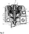
- FIGS 2-4 show different views of a possible structure of the membrane pressure relief valves SLV1, RFV1 and the hardener valve HV, which is also designed as a membrane pressure relief valve.
- the pressure relief valve has an inlet 1 for supplying a fluid (e.g. hardener, base paint) and an outlet 3 for discharging the coating agent.
- a fluid e.g. hardener, base paint
- the flow of the coating agent from the inlet 1 to the outlet 3 is controlled by a needle valve.
- the needle valve has a displaceable valve needle 4, a needle head 5 being screwed onto the distal end of the valve needle 4.
- the needle head 5 is made of titanium and tapers conically towards its end, with an annular groove in which a sealing ring 6 made of FFKM (perfluorinated rubber) is inserted in the conically tapering outer surface of the needle head 5.
- valve seat 7 In the closed position according to Figure 2 If the needle head 5 with the sealing ring 6 rests in a sealing manner on a valve seat 7, the valve seat 7 likewise tapers conically and opens into the outlet 3.
- valve drive 8 which is shown in Figure 3 is shown in detail and works pneumatically.
- the pneumatic valve drive thus has an outer housing insert 9 which is screwed into a housing body 10 of the two-component shut-off valve.
- An inner housing insert 11 is in turn screwed into the outer housing insert 9.
- a piston 12 is arranged displaceably in the pneumatic valve drive 8, the piston 12 being supported by a valve spring 13 in the direction of the closed position according to FIG Figure 1A is biased.
- the valve spring 13 is supported on the outer housing insert 9 and presses at its opposite end against the piston 12 in order to press it into the closed position.
- the piston 12 is connected to the valve needle 4 via a piston insert 14 so that the piston 12 acts on the valve needle 4 and thus also on the needle head.
- the piston 12 is surrounded by a sealing ring 15, which is arranged in the annular gap between the piston 12 on the one hand and the inner wall of the inner housing insert 11 and, when the piston 12 moves, rubs against the inner wall of the inner housing insert 11.
- valve needle 4 runs partially through a valve chamber 17 which is filled with the respective fluid (e.g. hardener, base paint) during operation.
- the respective fluid e.g. hardener, base paint
- a flexible membrane 18 is provided as a sealing element between the valve drive 8 and the media-filled valve chamber 17 in order to seal the valve chamber 17 with respect to the valve drive 8.
- the flexible membrane 18 is sealingly fastened with its outer peripheral edge to the lower end of the inner housing insert 11 and has a central bore through which the valve needle 4 is passed.
- the membrane 18 is fluid-tight and firmly connected to the valve needle 4. On the one hand, the membrane 18 thus takes part in the displacement movement of the valve needle 4 between the closed position and the open position.
- the membrane 4 also seals the media-filled valve chamber 17 from the valve drive 8, whereby no grinding movement is required as is the case with a sealing ring, so that there is also no risk of the low-viscosity and creeping hardener H being able to penetrate the valve drive 8.
- control air which can be introduced into a control air space 19 below the piston 12, the control air in the control air space 19 then pushing the piston 12 upwards.
- the control air is fed into the control air space 19 via a control air connection 20.
- the control air can be provided from a conventional 6-bar compressed air network, which is usually available in paint shops anyway. This offers the advantage that there is no need for a separate compressed air supply can.
- the piston 12 here has a relatively large effective diameter, so that the control air acting on the piston generates a relatively large opening force. When compressed air is applied by the control air, this opening force is greater than the closing force which the valve spring 13 exerts on the piston 12 by a certain excess opening force. In this specific exemplary embodiment, this excess opening force is in the range from 57.4 N to 136 N compared to an excess opening force of only 15 N in a conventional needle valve. This enables the needle head 5 to be “torn loose” from the valve seat 7 even when the needle head 5 adheres to the valve seat 7.
- the conical outer surface of the needle head 5 upstream in front of the sealing ring 6 here forms a support surface 21, which is in the closed position according to FIG Figure 2 is supported on the valve seat 7.
- the support surface 21 forms a stop for the axial movement of the needle head 5 into the closed position. This prevents excessive compression of the sealing ring 6, which is beneficial to the service life of the sealing ring 6.
- the support surface 21 is interrupted here by a plurality of axially running flushing grooves 22 which are arranged distributed over the circumference of the needle head 5.
- the flushing grooves 22 enable in the closed position according to FIG Figure 2 that flushing agent can also reach the area downstream behind the support surface 21 from the inlet 1.
- FIG. 5 shows a modification of Figure 1 so that to avoid repetition, reference is made to the above description, the same reference symbols being used for corresponding details.
- a special feature of this exemplary embodiment is that three strands of coating agent run in the rotary atomizer RZ, namely one strand of coating agent for a hardener, one strand of coating agent for a master paint and one strand of coating agent for a one-component lacquer.
- the coating agent strand for the hardener consists of the line sections L8 and L7.
- the coating agent strand for the base paint on the other hand, consists of line sections L1, L3 and L4.
- the separate line of coating agent for the one-component paint on the other hand, consists of the line section L12.
- the difference compared to the embodiment according to Figure 1 consists essentially in the fact that a separate coating agent strand is provided for the one-component paint, whereas with Figure 1 the coating agent strand consisting of the line sections L1, L12 serves either to supply the base paint or to supply the one-component paint.
- FIG. 6 shows a simplification of Figure 1 so that to avoid repetition, reference is made to the above description, the same reference symbols being used for corresponding details.
- a special feature of this exemplary embodiment is that it is only possible to apply a two-component lacquer, so that only two strands of coating agent are provided in order to apply base lacquer or hardener.
- the coating agent strand for the hardener consists of the line sections L6, L10 and L4.
- the coating agent strand for the main paint on the other hand, consists of the line sections L1, L2, L3 and L4.
- a special feature of this embodiment is that a total of four strands of coating agent run in the rotary atomizer, namely for base paint 1 and hardener 1 of a first two-component paint and for base paint 2 and hardener 2 of a second two-component paint.
- the fluid circuit diagram is therefore essentially in accordance with Figure 4 parallelized and doubled.
- the components for the first two-component paint are opposite Figure 6 with the addition ".1".
- the components for the second two-component paint are opposite Figure 6 with the addition ".2". Otherwise, reference can be made to the description above.
Description
- Die Erfindung betrifft ein Applikationsgerät, insbesondere einen Rotationszerstäuber, zur Applikation eines Beschichtungsmittels.
- Aus dem Stand der Technik sind Zweikomponentenlacke (2K-Lacke) bekannt, die aus zwei Komponenten bestehen, nämlich einem Härter (z. B. Isocyanat) und einem Stammlack. Bei der Förderung derartiger 2K-Lacke in einer Lackieranlage kommen als Absperrventile üblicherweise Nadelventile zum Einsatz, die eine verschiebbare Ventilnadel aufweisen. Die Ventilnadel verläuft hierbei durch einen Ventilraum, der im Betrieb mit dem 2K-Lack gefüllt ist, wobei der Ventilraum gegenüber dem auf die Ventilnadel wirkenden Ventilantrieb durch einen Dichtungsring abgedichtet ist. Der Dichtungsring schleift dabei mit seiner Innenseite auf der äußeren Mantelfläche der Ventilnadel und liegt mit seinem äußeren Umfang an der Innenwand des Ventilraums an.
- Problematisch hierbei ist die Tatsache, dass der Härter (z. B. Isocyanat) in der Regel mit Wasser reagiert und dann aushärtet. Hierbei reichen bereits geringste Mengen Wasser aus, um den Aushärtungsprozess zu starten, sodass beispielsweise die normale Luftfeuchtigkeit bereits zum Aushärten führt. Dies ist problematisch, weil der 2K-Lack oder der verwendete Härter sehr kriechfähig und niederviskos ist und deshalb den Dichtring um die Ventilnadel unterwandern kann, sodass der 2K-Lack bzw. der Härter aus dem lackgefüllten Ventilraum in den Bereich des Ventilantriebs austreten kann.
- Dies kann insbesondere bei längeren Stillstandszeiten (z. B. an Wochenenden) zu einem unerwünschten Aushärten des 2K-Lacks bzw. des Härters führen. Beispielsweise kann der ausgehärtete 2K-Lack die Ventilnadel im Ventilsitz festkleben. Darüber hinaus kann der 2K-Lack an der Ventilnadel anhaften und dann im ausgehärteten Zustand den umgebenden Dichtring beschädigen, was zu einer Undichtigkeit führt. Weiterhin können ausgehärtete Ablagerungen im Ventilsitz dazu führen, dass das Ventil nicht mehr schließt. Ferner können Aushärtungen dazu führen, dass das Ventil langsamer schließt.
- Besonders problematisch ist ein Ventilversagen, wenn das Ventil nicht mehr öffnen kann, da es dann stromaufwärts vor dem Ventil zu einer Überdruckstörung kommen kann, die im Extremfall zu einem Bersten der Zuleitungsschläuche führen kann, wodurch 2K-Lack bzw. Härter austreten kann, was dann erhebliche Stillstandszeiten für Reinigungs- und Reparaturarbeiten nach sich zieht.
- Schließlich kann es im Bereich der Nadelspitze zu einer chemischen Reaktion zwischen dem Medium (2K-Lack bzw. Härter) einerseits und dem Werkstoff der Nadelspitze bzw. des Ventilsitzes kommen, was ebenfalls zu einer Verklebung führen kann, wodurch das Ventil nicht mehr öffnen kann.
- Zum allgemeinen technischen Hintergrund der Erfindung ist auch hinzuweisen auf
DE 297 19 535 U1 . - Ferner offenbart die ältere, nachveröffentlichte europäische Patentanmeldung
EP 2 990 124 A1 ein druckluftbetätigtes Beschichtungsmittelventil, das den Beschichtungsmittelstrom zu einem Applikationsgerät steuert. - Die Betätigung des Beschichtungsmittelventils erfolgt hierbei ausschließlich durch Druckluft und das Beschichtungsmittelventil ist baulich getrennt von dem Applikationsgerät.
- Schließlich offenbart
DE 27 47 707 A1 ein Applikationsgerät gemäß dem Oberbegriff von Anspruch 1. Hierbei sind jedoch zur Steuerung des Beschichtungsmittelstroms und zum Überdruckschutz separate Ventile erforderlich. - Der Erfindung liegt deshalb die Aufgabe zugrunde, ein entsprechend verbessertes Applikationsgerät zu schaffen, das bei einem Ventilversagen (d. h. einem Verkleben eines Ventils) verhindert, dass Zuleitungen bersten können. Darüber hinaus kann es wünschenswert sein, auch grundsätzlich ein Versagen eines Ventils zu verhindern, was auch bei 1K-Zerstäubern vorteilhaft ist.
- Diese Aufgabe wird durch ein erfindungsgemäßes Applikationsgerät gemäß dem Hauptanspruch gelöst.
- Das erfindungsgemäße Applikationsgerät (z. B. Rotationszerstäuber) weist zunächst in Übereinstimmung mit dem Stand der Technik einen ersten Beschichtungsmittelanschluss auf, über den ein erstes Beschichtungsmittel zugeführt werden kann, wie beispielsweise ein Stammlack eines Zweikomponentenlacks (2K-Lack).
- Hierbei ist zu erwähnen, dass der im Rahmen der Erfindung verwendete Begriff eines Applikationsgeräts nicht beschränkt ist auf das bevorzugte Ausführungsbeispiel eines Rotationszerstäubers, wobei derartige Rotationszerstäuber als Absprühelement einen rotierenden Glockenteller oder eine rotierende Scheibe haben können. Andere mögliche Ausführungsbeispiele für erfindungsgemäße Applikationsgeräte sind Luftzerstäuber, Streifenzerstäuber (z. B. gemäß
DE 10 2013 002 412 A1 ), Handpistolen, Scheibenzerstäuber, Airless-Zerstäuber, Airmix-Zerstäuber und Ultraschallzerstäuber, um nur einige Beispiele zu nennen. - Ferner ist zu erwähnen, dass die Erfindung hinsichtlich des applizierten Beschichtungsmittels nicht auf Lacke oder Lackbestandteile beschränkt ist. Vielmehr kann es sich bei dem Beschichtungsmittel auch um andere Fluide handeln, wie beispielsweise Dichtmittel, Dämmstoff oder Klebstoff, um nur einige Beispiele zu nennen.
- In diesem Zusammenhang ist auch zu erwähnen, dass die Erfindung nicht beschränkt ist auf Einkomponenten-Beschichtungsmittel oder Zweikomponenten-Beschichtungsmittel, sondern auch bei Mehrkomponenten-Beschichtungsmitteln anwendbar ist, die beispielsweise drei Komponenten aufweisen können.
- Darüber hinaus weist das erfindungsgemäße Applikationsgerät in Übereinstimmung mit dem Stand der Technik einen ersten Beschichtungsmittelstrang auf, der in dem Applikationsgerät von dem ersten Beschichtungsmittelanschluss ausgeht und das erste Beschichtungsmittel führt.
- In diesem ersten Beschichtungsmittelstrang ist in Übereinstimmung mit dem Stand der Technik ein steuerbares erstes Ventil angeordnet, das den Strom des ersten Beschichtungsmittels durch den ersten Beschichtungsmittelstrang steuert, wobei dieses erste Ventil durch ein erstes Steuersignal steuerbar ist.
- Bei dem Steuersignal kann es sich beispielsweise um ein elektrisches Steuersignal oder um ein pneumatisches Steuersignal handeln, jedoch ist die Erfindung hinsichtlich der Steuerung der Ventile nicht auf diese Beispiele beschränkt.
- Das erfindungsgemäße Applikationsgerät zeichnet sich nun gegenüber dem Stand der Technik dadurch aus, dass in dem ersten Beschichtungsmittelstrang ein eigenmediumbetätigtes erstes Überdruckventil angeordnet ist, das zur Vermeidung einer Überdruckstörung automatisch öffnet, wenn der Druck stromaufwärts vor dem ersten Überdruckventil einen bestimmten Maximaldruck überschreitet. Falls es also in dem ersten Beschichtungsmittelstrang zu einer Überdruckstörung kommt, weil ein Ventil in dem ersten Beschichtungsmittelstrang versagt und nicht mehr öffnet, so wird ein Bersten der Zuleitungen verhindert, weil das erste Überdruckventil dann automatisch öffnet. Bei dem ersten Überdruckventil handelt es sich also um ein eigenmediumbetätigtes Überdruckventil, das in Abhängigkeit von dem eingangsseitig anliegenden Fluiddruck öffnet bzw. schließt.
- Vorzugsweise sind alle überdruckgefährdeten Fluidstränge in dem Applikationsgerät durch derartige Überdruckventile abgesichert, um bei Überdruckstörungen einen Druckabbau zu ermöglichen. Dies kann alle Fluidstränge in dem Applikationsgerät umfassen, beispielsweise für Stammlack, Härter, fertig gemischten Zweikomponentenlack, Einkomponentenlack, Lösemittel (Spülmittel).
- Gemäß der Erfindung wird das erste Überdruckventil durch das steuerbare erste Ventil gebildet. Dies bedeutet, dass das erste Ventil zwei Funktionen erfüllt. Zum einen ermöglicht das erste Ventil eine Steuerung des Fluidstroms durch den ersten Beschichtungsmittelstrang. Zum anderen funktioniert das erste Ventil aber auch als Überdruckventil und öffnet automatisch (eigenmediumbetätigt), wenn der eingangsseitig anliegende Druck einen bestimmten Maximaldruck überschreitet.
- In dem bevorzugten Ausführungsbeispiel der Erfindung führt der erste Beschichtungsmittelstrang zu einem Applikationselement, welches das erste Beschichtungsmittel appliziert. Beispielsweise kann es sich bei diesem Applikationselement um einen Glockenteller bzw. um eine Farbdüse in einem Glockenteller handeln, jedoch ist die Erfindung hinsichtlich des Typs des Applikationselements nicht auf dieses Beispiel beschränkt.
- Hierbei ist in dem ersten Beschichtungsmittelstrang zwischen dem ersten Überdruckventil und dem Applikationselement ein erstes Hauptventil angeordnet, welches den Fluidstrom in dem ersten Beschichtungsmittelstrang entweder absperrt oder freigibt. Vorzugsweise ist das erste Hauptventil als Hauptnadelventil ausgebildet und weist eine verschiebbare Ventilnadel auf, die einen Ventilsitz wahlweise freigibt oder versperrt.
- Derartige Nadelventile sind an sich aus dem Stand der Technik bekannt und müssen deshalb nicht näher beschrieben werden.
- In dem bevorzugten Ausführungsbeispiel der Erfindung weist das Applikationsgerät einen zweiten Beschichtungsmittelanschluss auf, um ein zweites Beschichtungsmittel zuzuführen, wie beispielsweise einen Härter des 2K-Lacks. Von diesem zweiten Beschichtungsmittelanschluss geht dann ein zweiter Beschichtungsmittelstrang aus, wobei in dem zweiten Beschichtungsmittelstrang ein zweites Überdruckventil angeordnet ist, das ebenfalls eigenmediumbetätigt ist und automatisch öffnet, wenn der Druck stromaufwärts vor dem ersten Überdruckventil einen bestimmten Maximaldruck überschreitet. Der zweite Beschichtungsmittelstrang mündet vorzugsweise stromaufwärts vor dem ersten Hauptventil in den ersten Beschichtungsmittelstrang, was eine Mischung des Stammlacks mit dem Härter ermöglicht.
- In dem ersten Beschichtungsmittelstrang ist deshalb vorzugsweise zwischen der Einmündungsstelle des zweiten Beschichtungsmittelstrangs und dem ersten Hauptventil ein Mischer angeordnet, der den Stammlack mit dem Härter zu dem 2K-Lack mischt.
- Der Mischer ist vorzugsweise als statischer Mischer ausgebildet, beispielsweise als Gittermischer oder als Wendelmischer. Derartige Mischer sind beispielsweise aus
DE 10 2010 019 771 A1 bekannt, so dass der Inhalt dieser Druckschrift der vorliegenden Beschreibung hinsichtlich des Aufbaus und der Funktionsweise des Mischers in vollem Umfang zuzurechnen ist. - Darüber hinaus weist das erfindungsgemäße Applikationsgerät vorzugsweise einen ersten Rückführanschluss auf, um Fluide (z. B. Reste des Stammlacks) in eine erste Rückführung zurückzuführen. Hierbei zweigt von dem ersten Beschichtungsmittelstrang stromaufwärts vor dem ersten Überdruckventil ein erster Rückführstrang ab, der in den ersten Rückführanschluss mündet. In dem ersten Rückführstrang ist hierbei vorzugsweise ein drittes Überdruckventil angeordnet, das ebenfalls eigenmediumbetätigt ist und automatisch öffnet, wenn der Druck in dem ersten Rückführstrang stromaufwärts vor dem dritten Überdruckventil einen bestimmten Maximalwert überschreitet.
- Ferner weist das erfindungsgemäße Applikationsgerät vorzugswese einen ersten Lösemittelanschluss auf, um ein erstes Lösemittel zuzuführen, wobei das erste Lösemittel vorzugsweise für den Stammlack vorgesehen ist. Von diesem ersten Lösemittelanschluss geht vorzugsweise ein erster Lösemittelstrang aus, wobei der erste Lösemittelstrang vorzugsweise in den ersten Beschichtungsmittelstrang mündet und zwar zwischen dem ersten Überdruckventil und dem ersten Hauptventil. Hierbei ist in dem ersten Lösemittelstrang vorzugsweise ein erstes Lösemittelventil angeordnet, das steuerbar ist, und den Lösemittelstrom freigibt oder sperrt.
- Darüber hinaus weist das erfindungsgemäße Applikationsgerät vorzugsweise einen Pulsluftanschluss auf, um zu Reinigungszwecken Pulsluft zuzuführen, was an sich aus dem Stand der Technik bekannt ist. Von diesem Pulsluftanschluss geht vorzugsweise ein Pulsluftstrang aus, der in den ersten Beschichtungsmittelstrang mündet und zwar vorzugsweise zwischen dem ersten Überdruckventil und dem ersten Hauptventil, wobei in dem Pulsluftstrang ein Pulsluftventil angeordnet sein kann, um die Pulsluft zu steuern.
- Weiterhin umfasst das erfindungsgemäße Applikationsgerät vorzugsweise einen zweiten Lösemittelanschluss zur Zuführung eines zweiten Lösemittels, das vorzugsweise für den Härter vorgesehen ist. Von diesem zweiten Lösungsmittelanschluss geht dann vorzugsweise ein zweiter Lösemittelstrang aus, der in den ersten Beschichtungsmittelstrang mündet und zwar zwischen dem ersten Überdruckventil und dem ersten Hauptventil, wobei in dem zweiten Lösemittelstrang vorzugsweise ein zweites Lösemittelventil angeordnet ist. Dieses zweite Lösemittelventil ist vorzugsweise steuerbar, um den Lösemittelstrom wahlweise freizugeben oder zu sperren.
- In dem erfindungsgemäßen Applikationsgerät geht von dem ersten Beschichtungsmittelanschluss vorzugsweise auch ein dritter Beschichtungsmittelstrang aus, wobei in dem dritten Beschichtungsmittelstrang ein zweites Hauptventil angeordnet sein kann, insbesondere in einer Bauweise als Hauptnadelventil, was an sich aus dem Stand der Technik bekannt ist und deshalb nicht näher beschrieben werden muss. Das erste Hauptventil und das zweite Hauptventil sind dann vorzugsweise ausgangsseitig zusammengeführt und führen zu dem Applikationselement (z. B. Glockenteller). Bei dieser Bauweise kann das Applikationsgerät also wahlweise zur Applikation eines Einkomponentenlackes oder zur Applikation eines Zweikomponentenlackes eingesetzt werden.
- Ferner weist das erfindungsgemäße Applikationsgerät vorzugsweise einen zweiten Rückführanschluss auf, um Fluide (z. B. Pulsluft, Lackschaum) in eine zweite Rückführung zurückzuführen. Von dem dritten Beschichtungsmittelstrang zweigt dann vorzugsweise stromaufwärts vor dem zweiten Hauptventil ein zweiter Rückführstrang ab, der in den zweiten Rückführanschluss mündet, wobei in diesem zweiten Rückführstrang vorzugsweise ein Rückventil angeordnet ist. Dieses Rückführventil ist vorzugsweise eigenmediumbetätigt, wobei das Rückführventil vorzugsweise konstruktionsbedingt zwischen flüssigem Beschichtungsmittel am Eingang einerseits und Druckluft oder Schaum am Eingang andererseits unterscheidet. Das Rückführventil öffnet dann selbsttätig, wenn am Eingang des Rückführventils Druckluft oder Schaum anliegt. Das Rückführventil schließt dagegen, wenn am Eingang des Rückführventils flüssiges Beschichtungsmittel anliegt. Das Rückführventil kann deshalb auch als Farbstoppventil bezeichnet werden, da es automatisch schließt, wenn am Eingang des Rückführventils anstelle von Druckluft oder Schaum flüssiger Lack anliegt. Der Aufbau und die Funktionsweise eines solchen Farbstoppventils ist ausführlich in
DE 10 2009 020 064 A1 beschrieben, so dass der Inhalt dieser Druckschrift der vorliegenden Beschreibung hinsichtlich des Aufbaus und der Funktionsweise des Rückführventils (Farbstoppventils) in vollem Umfang zuzurechnen ist. - Darüber hinaus weist das erfindungsgemäße Applikationsgerät vorzugsweise mindestens einen Kurzspülanschluss auf, um ein Spülmittel für eine Kurzspülung des Applikationsgeräts zuzuführen. Von dem Kurzspülanschluss geht dann mindestens ein Kurzspülstrang aus, der das Spülmittel unter Umgehung der Beschichtungsmittelstränge zu dem Applikationselement leiten kann. Hierbei ist in dem Kurzspülstrang vorzugsweise ein steuerbares Kurzspülventil angeordnet, das den Strom des Spülmittels wahlweise freigibt oder sperrt.
- Weiterhin ist zu erwähnen, dass die Überdruckventile im geöffneten Zustand vorzugsweise eine druckstoßdämpfende Funktion haben, so dass eingangsseitig eingehende Druckstöße ausgangsseitig nur gedämpft weitergegeben werden. Dies kann beispielsweise dadurch erreicht werden, dass die Überdruckventile als Membranventil ausgebildet sind, was noch detailliert beschrieben wird.
- Die Erfindung umfasst auch die technische Lehre, dass es sich bei dem Überdruckventil um ein besonderes Nadelventil handelt. Das erfindungsgemäße Nadelventil weist zunächst in Übereinstimmung mit dem Stand der Technik einen Ventilsitz und eine verschiebbare Ventilnadel mit einem Nadelschaft und einem Nadelkopf auf. Die Ventilnadel ist hierbei zwischen einer Schließstellung und einer Öffnungsstellung verschiebbar. In der Schließstellung verschließt der Nadelkopf der Ventilnadel den Ventilsitz und sperrt dadurch den Fluidstrom. In der Öffnungsstellung ist die Ventilnadel dagegen von dem Nadelkopf abgehoben und gibt dadurch den Fluidstrom frei.
- Zwischen der Öffnungsstellung und der Schließstellung können in einer Erfindungsvariante verschiedene Zwischenstellungen der Ventilnadel kontinuierlich eingestellt werden, um den Fluidstrom nicht nur qualitativ (auf/zu) zu steuern, sondern auch quantitativ, d. h. mit einem einstellbaren Strömungswiderstand. In einer anderen Erfindungsvariante steuert das Nadelventil den Fluidstrom dagegen nur qualitativ, indem der Fluidstrom entweder freigegeben oder gesperrt wird.
- Die Erfindung sieht nun vor, dass der die Ventilnadel umgebende und im Betrieb mediengefüllte Ventilraum durch eine flexible Membran abgedichtet wird, welche die Ventilnadel stromaufwärts vor dem Nadelkopf ringförmig und dichtend umgibt. Die flexible Membran verhindert zuverlässig, dass Beschichtungsmittel (z. B. Härter) aus dem mediengefüllten Ventilraum in Richtung des Ventilantriebs austritt und dort aushärtet.
- In einem bevorzugten Ausführungsbeispiel der Erfindung ist die Ventilnadel in dem Ventilraum verschiebbar angeordnet, wobei der Ventilraum zumindest abschnittsweise zylindrisch ist. Die Membran liegt dann an ihrer Mitte vorzugsweise dichtend an dem Nadelschaft der Ventilnadel an und ist an dem Nadelschaft der Ventilnadel befestigt. Dies bedeutet, dass die Membran nicht an der Ventilnadel schleift, sondern die Verschiebebewegung der Ventilnadel zwischen der Öffnungsstellung und der Schließstellung mitmacht. Dies bedeutet, dass eine Verschiebung der Ventilnadel zu einer entsprechenden axialen Auslenkung der Membran führt. Umgekehrt führt auch eine axiale Auslenkung der Membran, beispielsweise aufgrund einer einseitigen Druckbeaufschlagung der Membran, zu einer entsprechenden Verschiebung der Ventilnadel. An ihrem Umfangsrand ist die Membran dagegen dichtend an der Innenwand des Ventilraums befestigt. Die Membran ermöglicht also mittig einen axialen Hub, der mindestens so groß ist, wie der axiale Abstand zwischen der Schließstellung und der Öffnungsstellung der Ventilnadel, damit die Membran die Bewegung der Ventilnadel nicht behindert.
- In dem bevorzugten Ausführungsbeispiel der Erfindung weist das Nadelventil einen Ventilantrieb zum Verschieben der Ventilnadel auf, wobei der Ventilantrieb beispielsweise als pneumatischer Ventilantrieb mit einem Kolben ausgebildet sein kann, was an sich aus dem Stand der Technik bekannt ist und deshalb nicht näher beschrieben werden muss.
- Darüber hinaus weist das erfindungsgemäße Nadelventil vorzugsweise einen Beschichtungsmitteleinlass auf, um das Beschichtungsmittel (z. B. 2K-Lack oder Härter) zuzuführen, wobei der Beschichtungsmitteleinlass vorzugsweise auf der dem Ventilantrieb abgewandten Seite der Membran in den Ventilraum mündet, sodass die Membran den Ventilantrieb gegenüber dem beschichtungsmittelgefüllten Ventilraum abdichtet.
- Weiterhin enthält das erfindungsgemäße Nadelventil vorzugsweise einen Beschichtungsmittelauslass, um das Beschichtungsmittel abzugeben, wobei der Beschichtungsmittelauslass vorzugsweise in den Ventilsitz mündet, sodass das Beschichtungsmittel in der Öffnungsstellung der Ventilnadel durch den Ventilsitz zu dem Beschichtungsmittelauslass strömen kann.
- Es wurde bereits vorstehend erwähnt, dass das erfindungsgemäße Nadelventil einen Ventilantrieb aufweisen kann, um die Ventilnadel zu verschieben. In dem bevorzugten Ausführungsbeispiel der Erfindung umfasst dieser Ventilantrieb einen verschiebbaren Kolben, der auf die Ventilnadel wirkt, um die Ventilnadel zu verschieben. Der Kolben wird vorzugsweise pneumatisch angetrieben. Hierzu weist das Nadelventil vorzugsweise einen Steuerlufteinlass auf, um Steuerluft zuzuführen, wobei die Steuerluft auf den Kolben wirkt, um den Kolben und damit auch die Ventilnadel zu verschieben.
- Ferner umfasst das erfindungsgemäße Nadelventil vorzugsweise eine Ventilfeder, die mit einer Federkraft auf den Kolben oder die Ventilnadel wirkt. Die Ventilfeder einerseits und die Steuerluft andererseits wirken hierbei vorzugsweise in entgegengesetzte Richtungen.
- Weiterhin ist zu erwähnen, dass die Federkraft der Ventilfeder vorzugsweise mindestens 20 N, 40 N oder mindestens 80 N und/oder höchstens 400 N, 200 N oder 100 N beträgt, was vorzugsweise sowohl für die Schließstellung als auch für die Öffnungsstellung der Ventilfeder gilt.
- In dem bevorzugten Ausführungsbeispiel der Erfindung drückt die Ventilfeder die Ventilnadel in Richtung der Schließstellung, wohingegen die Steuerluft die Ventilnadel über den Kolben in Richtung der Öffnungsstellung drückt. Die Ventilfeder und der Nadelkopf sind dabei vorzugsweise auf gegenüberliegenden Seiten des Kolbens angeordnet.
- Hierbei ist zu erwähnen, dass der Kolben vorzugsweise einen relativ großen Kolbendurchmesser aufweist, um beim Bewegen der Ventilnadel in die Öffnungsstellung eine möglichst große Öffnungskraft zu erzeugen. Dabei ist zu berücksichtigen, dass die Öffnungskraft abhängt von der effektiven Kolbenfläche und damit auch vom Kolbendurchmesser und von dem pneumatischen Druck der Steuerluft. Der Kolben weist deshalb vorzugsweise einen Kolbendurchmesser von mindestens 5 mm, 10 mm, 15 mm, 20 mm, 25mm oder sogar 32 mm auf. Vorzugsweise ist der Kolbendurchmesser so groß, dass sich mit einem üblichen Steuerluftdruck von weniger als 6 bar eine ausreichend große Öffnungskraft realisieren lässt. Dies ist sinnvoll, weil in Lackieranlagen meist ohnehin übliche 6-bar-Druckluftnetze zur Verfügung stehen, die dann auch zur Ansteuerung des erfindungsgemäßen Nadelventils verwendet werden können. Auf diese Weise kann also auf ein separates Druckluftnetz zur Ansteuerung des Nadelventils verzichtet werden.
- Es wurde bereits vorstehend erwähnt, die Ventilfeder die Ventilnadel vorzugsweise in Richtung der Schließstellung drückt und zwar mit einer bestimmten Schließkraft. Der pneumatische Ventilantrieb drückt die Ventilnadel dagegen bei einer pneumatischen Ansteuerung mit einer bestimmten Öffnungskraft in Richtung der Öffnungsstellung. Hierbei sollte die Öffnungskraft des pneumatischen Ventilantriebs um einen bestimmten Öffnungskraftüberschuss größer sein als die Schließkraft, um das Nadelventil sicher öffnen zu können, wenn der Nadelkopf an dem Ventilsitz anhaftet. Das Nadelventil ist deshalb vorzugsweise so ausgelegt, dass der Öffnungskraftüberschuss größer ist als 20 N, 40 N, 60 N, 80 N, 100 N, 120 N, 130 N oder sogar 180 N.
- Bei der Beschreibung des Standes der Technik wurde eingangs bereits auf die Gefahr hingewiesen, dass die Beschichtungsmittelschläuche stromaufwärts vor dem Nadelventil bei einer Überdruckstörung auch durch Fehlbedienung oder Fehlinterpretation der Überdruckstörung bersten können, wodurch 2K-Lack oder Härter austreten können, was dann zu längeren Stillstandszeiten führt, da der ausgetretene 2K-Lack bzw. der ausgetretene Härter aushärtet. Nach dem Bersten kommt es zu keiner weiteren Überdruckstörung. Wenn die Bediener die Anlage wieder in Gang setzen, dann tritt ein Teil oder Großteil der Lackiermenge aus dem geborstenen Schlauch aus und flutet z. B. den gesamten Handachsbereich. Meist wird der Fehler dann erst entdeckt, wenn schon mehrere Liter ausgetreten sind und es zu anderen weiteren Störungen kommt, z. B. Drehzahlstörung, da die Turbinenabluft durch den Lack nicht mehr entweichen kann. Das erfindungsgemäße Nadelventil weist deshalb eine Überdruckfunktion auf, die beim Überschreiten eines bestimmten Öffnungsdrucks an dem Beschichtungsmitteleinlass zum automatischen Öffnen des Ventils führt. Hierzu drückt das in dem Ventilraum befindliche Beschichtungsmittel gegen die Membran, wodurch die Membran und damit auch die Ventilnadel aus der Schließstellung in die Öffnungsstellung gedrückt wird, wenn der Beschichtungsmitteldruck ausreichend groß ist, um die entgegen gerichtete Kraft der Ventilfeder zu überwinden. Die Membran weist deshalb vorzugsweise einen Membrandurchmesser von mindestens 3 mm, 6 mm oder 9 mm und/oder höchstens 40 mm, 20 mm oder 11 mm auf. Der Öffnungsdruck des Beschichtungsmittels an dem Beschichtungsmitteleinlass beträgt dann vorzugsweise mindestens 8 bar, 10 bar, 12 bar, 14 bar oder mindestens 38 bar und/oder höchstens 38 bar, 22 bar, 18 bar oder 16 bar. Die Schließkraft der Feder muss also so an den gewünschten Öffnungsdruck und den effektiven Querschnitt der Membran angepasst werden, dass der Beschichtungsmitteldruck in dem Ventilraum beim Überschreiten des gewünschten Öffnungsdrucks die Membran und damit auch die Ventilnadel aus der Schließstellung in die Öffnungsstellung drückt.
- Weiterhin ist zu erwähnen, dass sich der Ventilsitz vorzugsweise mit einem bestimmten Sitzwinkel in Strömungsrichtung verengt, wie sich auch der Nadelkopf vorzugsweise mit einem bestimmten Kopfwinkel in Strömungsrichtung verengt. In dem bevorzugten Ausführungsbeispiel ist der Sitzwinkel im Wesentlichen gleich dem Kopfwinkel. Beispielsweise kann der Sitzwinkel im Bereich von 35°-50° liegen, wie auch der Kopfwinkel vorzugsweise im Bereich von 35°-50° liegt, was eine optimale Abdichtung gewährleistet. Ein größerer Kopfwinkel verbessert hierbei den Durchfluss des Mediums bei den mit geringen Nadelhüben (ca. 1,5 mm anstelle von 3 mm bei herkömmlichen Nadelventilen) ausgestatteten erfindungsgemäßen Nadelventilen mit einer zusätzlichen Membran.
- In dem bevorzugten Ausführungsbeispiel der Erfindung ist in den Nadelkopf der Ventilnadel ein zusätzliches Dichtelement eingesetzt, um den Ventilsitz in der Schließstellung abzudichten. Dieses zusätzliche Dichtelement kann aus einem anderen Material bestehen als der Nadelkopf der Ventilnadel, wobei vorzugsweise ein elastisches Material zum Einsatz kommt, wie beispielsweise FFKM (Perfluorkautschuk). Beispielsweise kann das zusätzliche Dichtelement an dem Nadelkopf anvulkanisiert sein. Es besteht jedoch auch die Möglichkeit, dass das Dichtelement in den Nadelkopf eingesetzt ist, beispielsweise in eine Ringnut in dem Nadelkopf. Der Nadelkopf selbst kann hierbei beispielsweise aus Titan oder aus einer Titanlegierung bestehen, damit der Nadelkopf gegenüber chemisch aggressiven Härtern von 2K-Lacken widerstandsfähig ist.
- Es wurde bereits vorstehend kurz erwähnt, dass sich der Nadelkopf und der Ventilsitz vorzugsweise in Strömungsrichtung im Wesentlichen konisch verjüngen. Hierbei kann der Nadelkopf eine Ringnut aufweisen, in die das bereits vorstehend kurz erwähnte Dichtungselement eingesetzt sein kann. Hierbei kann das Problem auftreten, dass die auf die Ventilnadel wirkende Schließkraft vollständig von dem Dichtelement aufgenommen wird, was dann zu einer mechanischen Überlastung und Beschädigung des Dichtelements führen kann. Dies kann dadurch verhindert werden, dass der Nadelkopf einen starren Anschlag aufweist und sich in der Schließstellung mit dem Anschlag an dem Ventilsitz abstützt. Beim Schließen des Ventils wird das Dichtelement in dem Nadelkopf also nur so weit auf Druck beansprucht, bis die Ventilnadel mit ihrem Anschlag an dem Ventilsitz anliegt. Auf diese Weise wird die Kompression des Dichtelements in dem Nadelkopf beim Schließen des Ventils begrenzt, was der Lebensdauer des Dichtelements zuträglich ist. In dem bevorzugten Ausführungsbeispiel der Erfindung wird dieser Anschlag durch eine ringförmig umlaufende Abstützfläche gebildet, die in der konischen Mantelfläche des Nadelkopfs stromaufwärts vor dem Dichtelement liegt. Hierbei kann das Problem bestehen, dass das Dichtelement den Bereich des Nadelkopfs stromabwärts hinter dem Dichtelement abdichtet, sodass dieser Bereich bei einem Spülvorgang nicht von dem Spülmittel erreichbar ist. Dieses Problem kann im Rahmen der Erfindung dadurch gelöst werden, dass die Abstützfläche mindestens eine axial verlaufende Spülnut aufweist, durch die Spülmittel in axialer Richtung aus dem Ventilraum in den Bereich stromabwärts hinter dem Dichtelement eintreten kann. Beispielsweise kann eine solche Spülnut eine Nutbreite von 1 mm - 2 mm aufweisen.
- Im Rahmen der Erfindung besteht die Möglichkeit, dass die den Ventilraum abdichtende flexible Membran den Dichtring ersetzt, der bei herkömmlichen Nadelventilen vorhanden ist. Es besteht jedoch im Rahmen der Erfindung auch die Möglichkeit, dass zusätzlich zu der flexiblen Membran zur Abdichtung auch ein herkömmlicher Dichtring vorhanden ist, der die Ventilnadel ringförmig umgibt und schleifend auf der Mantelfläche der Ventilnadel anliegt.
- Der Nadelschaft der Ventilnadel weist vorzugsweise einen Durchmesser auf, der im Bereich von 2 mm - 10 mm, 3 mm - 6 mm oder 4 mm - 5 mm liegen kann. Der maximale Nadelhub der Ventilnadel ist dagegen vorzugsweise kleiner als 3 mm, 2,5 mm, 2 mm oder sogar kleiner als 1,6 mm.
- Im Rahmen der Erfindung sind verschiedene Varianten möglich, die sich durch die Anzahl der verschiedenen Beschichtungsmittelstränge innerhalb des Applikationsgerätes unterscheiden.
- Vorstehend wurde bereits eine erste Erfindungsvariante beschrieben, bei der innerhalb des Applikationsgerätes zwei Beschichtungsmittelstränge verlaufen. Der eine Beschichtungsmittelstrang ist hierbei für einen Härter eines Zweikomponentenlackes reserviert. Der andere Beschichtungsmittelstrang kann dagegen wahlweise für einen zugehörigen Stammlack des Zweikomponentenlackes oder für einen Einkomponentenlack verwendet werden.
- In einer anderen Erfindungsvariante verlaufen dagegen innerhalb des Applikationsgerätes drei Beschichtungsmittelstränge. Zwei der Beschichtungsmittelstränge sind hierbei für Stammlack bzw. Härter eines Zweikomponentenlackes reserviert. Der dritte Beschichtungsmittelstrang ist dagegen hierbei für einen Einkomponentenlack reserviert. Diese Erfindungsvariante unterscheidet sich also von der vorstehend beschriebenen Erfindungsvariante im Wesentlichen dadurch, dass für den Einkomponentenlack ein separater Beschichtungsmittelstrang vorgesehen ist, der weder vom Stammlack noch vom Härter durchströmt wird.
- Eine dritte Erfindungsvariante ist gegenüber der eingangs beschriebenen Erfindungsvariante vereinfacht und weist nur zwei Beschichtungsmittelstränge auf, nämlich einen Beschichtungsmittelstrang für einen Stammlack eines Zweikomponentenlackes und einen zweiten Beschichtungsmittelstrang für einen Härter des Zweikomponentenlackes. Im Gegensatz zu der eingangs beschriebenen ersten Erfindungsvariante ist es hierbei also nicht vorgesehen, über den Beschichtungsmittelstrang für den Stammlack alternativ auch einen Einkomponentenlack zuzuführen.
- Eine weitere Erfindungsvariante sieht dagegen vor, dass in dem Applikationsgerät vier Beschichtungsmittelstränge vorgesehen sind, nämlich zwei Beschichtungsmittelstränge für Stammlack bzw. Härter eines ersten Zweikomponentenlackes und zwei weitere Beschichtungsmittelstränge für Stammlack bzw. Härter eines zweiten Zweikomponentenlackes.
- Andere vorteilhafte Weiterbildungen der Erfindung sind in den Unteransprüchen gekennzeichnet oder werden nachstehend zusammen mit der Beschreibung der bevorzugten Ausführungsbeispiele näher erläutert. Es zeigen:
- Figur 1
- ein Fluidschaltbild eines erfindungsgemäßen Rotationszerstäubers an einem Lackierroboter,
- Figur 2
- eine Querschnittsansicht durch ein erfindungsgemäßes Überdruckventil in einer Schließstellung,
- Figur 3
- eine Querschnittsansicht durch einen Ventilantrieb des Überdruckventils gemäß
Figur 2 , - Figur 4
- eine schematische Darstellung eines konischen Nadelkopfs mit einem konischen Ventilsitz,
- Figur 5
- eine Abwandlung von
Figur 1 , wobei in dem Applikationsgerät drei Beschichtungsmittelstränge verlaufen, nämlich für Stammlack, Härter und alternativ einen Einkomponentenlack, - Figur 6
- eine Abwandlung von
Figur 1 , wobei der Stammlackstrang in dem Applikationsgerät für den Stammlack reserviert ist und nicht alternativ zur Zuführung eines Einkomponentenlacks dient, sowie - Figur 7
- eine Abwandlung von
Figur 1 mit vier Beschichtungsmittelsträngen in dem Applikationsgerät für Stammlack bzw. Zerstäuber von zwei verschieden Zweikomponentenlacken. -
Figur 1 zeigt einen erfindungsgemäßen Rotationszerstäuber RZ, der von einem Lackierroboter geführt wird und mittels einer herkömmlichen Roboterhandachse am Ende eines Roboterarms RA montiert ist. - In dem Roboterarm RA befindet sich ein Linearfarbwechsel LCC (LCC: Linear Color Changer), der beispielsweise aus
DE 10 2008 037 035 A1 bekannt ist. Ausgangsseitig ist der Linearfarbwechsler LCC über eine Dosierpumpe PSL mit einem Stammlackanschluss SL des Rotationszerstäubers RZ verbunden. Die Dosierpumpe PSL ist hierbei ebenfalls in dem Roboterarm RA angeordnet und kann durch eine Bypass-Leitung By1 umgangen werden. Die Funktion der Dosierpumpe PSL besteht in der Dosierung und Förderung eines Stammlacks eines Zweikomponentenlacks (2K-Lack) . - Darüber hinaus befindet sich in dem Roboterarm RA ein Lösemittelventil VSV1 zur Zuführung eines Lösemittels für den Stammlack, wobei das Lösemittelventil VSV1 ausgangsseitig mit einem Lösemittelanschluss VS1 für den Stammlack verbunden ist.
- Ferner befindet sich in dem Roboterarm RA auch eine Dosierpumpe PH zur Zuführung eines Härters für den Zweikomponentenlack, wobei die Dosierpumpe PH ausgangsseitig mit einem Härter-Anschluss H des Rotationszerstäubers RZ verbunden ist. Weiterhin befindet sich in dem Roboterarm RA ein Lösemittelventil VHV1 zur gesteuerten Zuführung eines Lösemittels für den Härter, wobei das Lösemittelventil VHV1 ausgangsseitig mit einem Lösemittelanschluss VH des Rotationszerstäubers RZ verbunden ist.
- Weiterhin enthält der Rotationszerstäuber RZ einen Pulsluftanschluss PL zur Zuführung von Pulsluft, einen Rückführanschluss RF1 zur Rückführung von Restmaterial, einen Rückführanschluss RF2 zur Rückführung von Pulsluft und Lackschaum sowie Kurzspülanschlüsse KS1, KS2 zur Zuführung eines Spülmittels zum Kurzspülen des Rotationszerstäubers.
- Der Stammlack-Anschluss SL des Rotationszerstäubers RZ ist mit einem Stammlackstrang verbunden, der aus Leitungsabschnitten L1-L4 besteht, die zu einem Mischer MIX und schließlich zu einem Hauptnadelventil HN1 führen, wobei das Hauptnadelventil HN1 mit einem Ausgang A2 verbunden ist, der zu einem Glockenteller führt.
- In dem Stammlackstrang, bestehend aus den Leitungsabschnitten L1-L4, befindet sich stromaufwärts vor dem Mischer MIX ein Membran-Überdruckventil SLV1, das in seinem Aufbau noch detailliert beschrieben wird. Das Membran-Überdruckventil SLV1 öffnet eigenmediumbetätigt selbstständig, wenn der Druck des Stammlacks stromaufwärts vor dem Membran-Überdruckventil SLV1 einen bestimmten Maximalwert überschreitet. Beim Öffnen des Membran-Überdruckventils SLV1 kann der Überdruck dann über den Mischer MIX und das Hauptnadelventil HN1 abgeführt werden. Dadurch wird verhindert, dass es in den Leitungsabschnitten L1, L2 stromaufwärts vor dem Membran-Überdruckventil SLV1 zu einer Überdruckstörung oder gar zu einem Bersten von Leitungen kommen kann.
- Von dem Leitungsabschnitt L2 des Stammlackstrangs zweigt ein Rückführstrang ab, der durch einen Leitungsabschnitt L5 gebildet wird und in den Rückführanschluss RF1 mündet. In dem Leitungsabschnitt L5 des Rückführstrangs ist hierbei ebenfalls ein Membran-Überdruckventil RFV1 angeordnet, das in gleicher Weise aufgebaut sein kann wie das Membran-Überdruckventil SLV1. Das Membran-Überdruckventil RFV1 hat die Aufgabe, einen Druckabbau zu ermöglichen, wenn das Hauptnadelventil HN1 defekt ist und nicht mehr öffnet. In diesem Fall kommt es nämlich zu einem Druckanstieg in dem Beschichtungsmittelstrang, der aus den Leitungsabschnitten L1-L4 besteht. Dieser Druckanstieg führt dann rechtzeitig vor einer Überdruckstörung zu einem automatischen Öffnen des Membran-Überdruckventils RFV1, so dass sich ein eventueller Überdruck in dem Stammlackstrang durch den Rückführstrang und den Rückführanschluss RF1 abbauen kann.
- Von dem Härter-Anschluss H geht ein Härterstrang aus, der aus Leitungsabschnitten L6, L7 besteht. Der Härterstrang mündet stromaufwärts vor dem Mischer MIX und stromabwärts hinter dem Membran-Überdruckventil SLV1 in den Stammlackstrang. Der Stammlack und der Härter werden deshalb in dem Mischer MIX gemischt.
- Von dem Lösemittelanschluss VH geht ein Lösemittelstrang aus, der durch einen Leitungsabschnitt L8 gebildet wird. In dem Leitungsabschnitt L8 des Lösemittelstrangs ist ein Lösemittelventil VHV2 angeordnet, das eine Steuerung des Lösemittelstroms ermöglicht.
- Von dem Pulsluftanschluss PL geht ein Pulsluftstrang aus, der durch Leitungsabschnitte L9, L10 gebildet wird. In dem Leitungsabschnitt L9 des Pulsluftstrangs ist ein steuerbares Pulsluftventil PLV angeordnet, das den Pulsluftstrom steuert.
- Von dem anderen Lösemittelanschluss VS1 geht ein weiterer Lösemittelstrang aus, der aus einem Leitungsabschnitt L11 und dem Leitungsabschnitt L10 besteht. In dem Leitungsabschnitt L11 des Lösemittelstrangs für den Stammlack ist ein Lösemittelventil VSV2 angeordnet, das den Lösemittelstrom steuern kann.
- Das Härterventil HV in dem Härterstrang ist ebenfalls als Membran-Überdruckventil ausgebildet und öffnet deshalb ebenfalls eigenmediumbetätigt, wenn der Druck des Härters stromaufwärts vor dem Härterventil HV einen bestimmten Maximalwert überschreitet. Der Überdruck in dem Härterstrang kann dann über die Leitungsabschnitte L7, L4, L3, das Membran-Überdruckventil SLV1, das Membran-Überdruckventil RFV1 und den Rückführanschluss RF1 abgebaut werden.
- Darüber hinaus weist der Rotationszerstäuber RZ noch einen weiteren Stammlackstrang auf, der aus dem bereits erwähnten Leitungsabschnitt L1 und einem weiteren Leitungsabschnitt L12 gebildet wird. In dem Leitungsabschnitt L12 des weiteren Stammlackstrangs ist ein Stammlackventil SLV2 angeordnet, das zu einem Hauptnadelventil HN2 führt. Die beiden Hauptnadelventile HN1, HN2 sind ausgangsseitig mit dem Ausgang A2 und damit mit dem Glockenteller verbunden. Über das Hauptnadelventil HN2 kann hierbei ein Einkomponentenlack appliziert werden. Über das Hauptnadelventil HN1 kann dagegen ein Zweikomponentenlack appliziert werden, der zuvor in dem Mischer MIX gemischt wird.
- Von dem Leitungsabschnitt L12 stromaufwärts vor dem zweiten Hauptnadelventil HN2 zweigt ein weiterer Rückführstrang ab, der aus einem Leitungsabschnitt L13 besteht, der in den Rückführanschluss RF2 mündet. In dem Leitungsabschnitt L13 des zweiten Rückführstrangs ist ein Rückführventil RFV2 angeordnet, das als Farbstoppventil ausgebildet ist. Das Rückführventil RFV2 öffnet also eigenmediumbetätigt, wenn am Eingang des Rückführventils RFV2 Druckluft oder Lackschaum anliegt. Das Rückführventil RFV2 schließt dagegen selbstständig und eigenmediumbetätigt, wenn am Eingang des Rückführventils RFV2 flüssiger Lack anliegt. Der Aufbau des Rückführventils RFV2 ist an sich aus dem Stand der Technik bekannt und beispielsweise in
DE 10 2009 020 064 A1 beschrieben. - Von den beiden Kurzspülanschlüssen KS1, KS2 geht jeweils ein Kurzspülstrang aus, der aus den Leitungsabschnitten L14 bzw. L15 besteht. In den beiden Leitungsabschnitten L14, L15 ist jeweils ein steuerbares Kurzspülventil KSV1 bzw. KSV2 angeordnet, wobei die beiden Kurzspülventile KSV1, KSV2 ausgangsseitig mit einem Ausgang A1 zum Kurzspülen verbunden sind. Die beiden Kurzspülstränge umgehen also bei einem Spülvorgang sowohl die beiden Stammlackstränge als auch den Härterstrang und ermöglichen somit ein Kurzspülen, was an sich aus dem Stand der Technik bekannt ist. Zwischen dem Ausgang der beiden Kurzspülventile KSV1, KSV2 einerseits und dem Ausgang der beiden Hauptnadelventile HN1, HN2 andererseits ist hierbei ein Rückschlagventil RV angeordnet.
- Zu der vorstehend beschriebenen Anordnung ist zu erwähnen, dass die Membran-Überdruckventile SFV1, RFV1 und das ebenfalls als Membran-Überdruckventil ausgebildete Härterventil HV durch eine schräge Schraffierung als solche gekennzeichnet sind. Das als Farbstoppventil ausgebildete Rückführventil RFV2 ist dagegen durch eine vollständig schwarze Füllung als Farbstoppventil gekennzeichnet. Die Hauptnadelventile HN1, HN2 sind dagegen durch eine senkrechte Schraffur als Nadelventil gekennzeichnet. Die restlichen Ventile sind durch eine weiße Füllung als herkömmliche Nadelventile gekennzeichnet.
- Die
Figuren 2-4 zeigen verschieden Ansichten eines möglichen Aufbaus der Membran-Überdruckventile SLV1, RFV1 und des ebenfalls als Membran-Überdruckventil ausgebildeten Härterventils HV. - Das Überdruckventil weist zur Zuführung eines Fluids (z. B. Härter, Stammlack) einen Einlass 1 und zur Abgabe des Beschichtungsmittels einen Auslass 3 auf.
- Die Strömung des Beschichtungsmittels von dem Einlass 1 zu dem Auslass 3 wird hierbei durch ein Nadelventil gesteuert. Das Nadelventil weist eine verschiebbare Ventilnadel 4 auf, wobei ein Nadelkopf 5 auf das distale Ende der Ventilnadel 4 aufgeschraubt ist. Der Nadelkopf 5 besteht hierbei aus Titan und verjüngt sich zu seinem Ende hin konisch, wobei in der konisch zulaufenden Mantelfläche des Nadelkopfs 5 eine Ringnut angeordnet ist, in die ein Dichtring 6 aus FFKM (Perfluorkautschuk) eingesetzt ist.
- In der Schließstellung gemäß
Figur 2 liegt der Nadelkopf 5 mit dem Dichtring 6 an einem Ventilsitz 7 dichtend an, wobei sich der Ventilsitz 7 ebenfalls konisch verjüngt und in den Auslass 3 mündet. - In der Öffnungsstellung (nicht dargestellt) ist der Nadelkopf 5 dagegen von dem Ventilsitz 7 abgehoben und gibt dadurch die Strömung durch den Ventilsitz 7 zu dem Auslass 3 frei.
- Die Einstellung der Schließstellung bzw. der Öffnungsstellung erfolgt hierbei durch einen Ventilantrieb 8, der in
Figur 3 detailliert dargestellt ist und pneumatisch arbeitet. - So weist der pneumatische Ventilantrieb einen äußeren Gehäuseeinsatz 9 auf, der in einen Gehäusekörper 10 des Zweikomponentenabsperrventils eingeschraubt ist.
- In den äußeren Gehäuseeinsatz 9 ist wiederum ein innerer Gehäuseeinsatz 11 eingeschraubt.
- In dem pneumatischen Ventilantrieb 8 ist ein Kolben 12 verschiebbar angeordnet, wobei der Kolben 12 von einer Ventilfeder 13 in Richtung der Schließstellung gemäß
Figur 1A vorgespannt wird. Die Ventilfeder 13 stützt sich hierbei an dem äußeren Gehäuseeinsatz 9 ab und drückt an ihrem gegenüberliegenden Ende gegen den Kolben 12, um diesen in die Schließstellung zu drücken. Der Kolben 12 ist hierbei über einen Kolbeneinsatz 14 mit der Ventilnadel 4 verbunden, sodass der Kolben 12 auf die Ventilnadel 4 und damit auch auf den Nadelkopf wirkt. - Der Kolben 12 ist hierbei von einem Dichtring 15 umgeben, der in dem Ringspalt zwischen dem Kolben 12 einerseits und der Innenwand des inneren Gehäuseeinsatzes 11 angeordnet ist und bei einer Bewegung des Kolbens 12 an der Innenwand des inneren Gehäuseeinsatzes 11 schleift.
- Darüber hinaus ist ein weiterer Dichtring 16 vorgesehen, der schleifend auf der Mantelfläche der verschiebbaren Ventilnadel 4 anliegt und dadurch eine weitere Abdichtung bewirkt. Die Ventilnadel 4 verläuft hierbei teilweise durch einen Ventilraum 17, der im Betrieb mit dem jeweiligen Fluid (z. B. Härter, Stammlack) gefüllt ist.
- Zwischen dem Ventilantrieb 8 und dem mediengefüllten Ventilraum 17 ist hierbei eine flexible Membran 18 als Dichtelement vorgesehen, um den Ventilraum 17 gegenüber dem Ventilantrieb 8 abzudichten. Die flexible Membran 18 ist mit ihrem äußeren Umfangsrand an dem unteren Ende der inneren Gehäuseeinsatzes 11 dichtend befestigt und weist mittig eine Bohrung auf, durch die die Ventilnadel 4 hindurchgeführt ist. Die Membran 18 ist hierbei fluiddicht und fest mit der Ventilnadel 4 verbunden. Zum einen macht die Membran 18 also die Verschiebebewegung der Ventilnadel 4 zwischen der Schließstellung und der Öffnungsstellung mit. Zum anderen dichtet die Membran 4 aber auch den mediengefüllten Ventilraum 17 gegenüber dem Ventilantrieb 8 ab, wobei keine Schleifbewegung wie bei einem Dichtring erforderlich ist, sodass auch nicht die Gefahr besteht, dass der niederviskose und kriechfähige Härter H in den Ventilantrieb 8 eindringen kann.
- Der eigentliche Antrieb erfolgt hierbei durch Steuerluft, die in einen Steuerluftraum 19 unterhalb des Kolbens 12 eingeleitet werden kann, wobei die Steuerluft in dem Steuerluftraum 19 dann den Kolben 12 nach oben drückt. Die Zuführung der Steuerluft in den Steuerluftraum 19 erfolgt hierbei über einen Steuerluftanschluss 20.
- Die Steuerluft kann hierbei aus einem herkömmlichen 6-bar-Druckluftnetz bereitgestellt werden, das in Lackieranlagen meist ohnehin zur Verfügung steht. Dies bietet den Vorteil, dass auf eine separate Druckluftversorgung verzichtet werden kann. Der Kolben 12 weist hierbei einen relativ großen effektiven Durchmesser auf, sodass die auf den Kolben wirkende Steuerluft eine relativ große Öffnungskraft erzeugt. Diese Öffnungskraft ist bei einer Druckluftbeaufschlagung durch die Steuerluft um einen bestimmten Öffnungskraftüberschuss größer als die Schließkraft, die die Ventilfeder 13 auf den Kolben 12 ausübt. Dieser Öffnungskraftüberschuss liegt in diesem konkreten Ausführungsbeispiel im Bereich von 57,4 N bis 136 N im Vergleich zu einem Öffnungskraftüberschuss von nur 15 N bei einem herkömmlichen Nadelventil. Dies ermöglicht ein "Losreißen" des Nadelkopfs 5 von dem Ventilsitz 7 auch dann, wenn der Nadelkopf 5 an dem Ventilsitz 7 anhaftet.
- Aus
Figur 4 ist weiterhin ersichtlich, dass sich der Nadelkopf 5 mit einem Kopfwinkel λ=35°-50° in Strömungsrichtung verjüngt, wie sich auch der Ventilsitz 7 mit einem Sitzwinkel β=35°-50° in Strömungsrichtung konisch verjüngt. - Die konische Mantelfläche des Nadelkopfs 5 stromaufwärts vor dem Dichtring 6 bildet hierbei eine Abstützfläche 21, die sich in der Schließstellung gemäß
Figur 2 an dem Ventilsitz 7 abstützt. Die Abstützfläche 21 bildet hierbei einen Anschlag für die Axialbewegung des Nadelkopfes 5 in die Schließstellung. Dadurch wird eine übermäßige Kompression des Dichtrings 6 verhindert, was der Lebensdauer des Dichtrings 6 zuträglich ist. - Die Abstützfläche 21 ist hierbei durch mehrere axial verlaufende Spülnuten 22 unterbrochen, die über den Umfang des Nadelkopfs 5 verteilt angeordnet sind. Die Spülnuten 22 ermöglichen in der Schließstellung gemäß
Figur 2 , dass Spülmittel von dem Einlass 1 auch den Bereich stromabwärts hinter der Abstützfläche 21 erreichen kann. -
Figur 5 zeigt eine Abwandlung vonFigur 1 , so dass zur Vermeidung von Wiederholungen auf die vorstehende Beschreibung verwiesen wird, wobei für entsprechende Einzelheiten dieselben Bezugszeichen verwendet werden. - Eine Besonderheit dieses Ausführungsbeispiels besteht darin, dass in dem Rotationszerstäuber RZ drei Beschichtungsmittelstränge verlaufen, nämlich ein Beschichtungsmittelstrang für einen Härter, ein Beschichtungsmittelstrang für einen Stammlack und ein Beschichtungsmittelstrang für einen Einkomponentenlack. Der Beschichtungsmittelstrang für den Härter besteht hierbei aus den Leitungsabschnitten L8 und L7. Der Beschichtungsmittelstrang für den Stammlack besteht dagegen aus den Leitungsabschnitten L1, L3 und L4. Der separate Beschichtungsmittelstrang für den Einkomponentenlack besteht dagegen aus dem Leitungsabschnitt L12. Der Unterschied gegenüber dem Ausführungsbeispiel gemäß
Figur 1 besteht im Wesentlichen darin, dass für den Einkomponentenlack ein separater Beschichtungsmittelstrang vorgesehen ist, wohingegen beiFigur 1 der Beschichtungsmittelstrang bestehend aus den Leitungsabschnitten L1, L12 wahlweise zur Zuführung des Stammlacks oder zur Zuführung des Einkomponentenlacks dient. -
Figur 6 zeigt eine Vereinfachung vonFigur 1 , so dass zur Vermeidung von Wiederholungen auf die vorstehende Beschreibung verwiesen wird, wobei für entsprechende Einzelheiten dieselben Bezugszeichen verwendet werden. - Eine Besonderheit dieses Ausführungsbeispiels besteht darin, dass nur die Möglichkeit besteht, einen Zweikomponentenlack zu applizieren, so dass auch nur zwei Beschichtungsmittelstränge vorgesehen sind, um Stammlack bzw. Härter zu applizieren. Der Beschichtungsmittelstrang für den Härter besteht hierbei aus den Leitungsabschnitten L6, L10 und L4. Der Beschichtungsmittelstrang für den Stammlack besteht dagegen aus den Leitungsabschnitten L1, L2, L3 und L4. Es ist dagegen bei diesem Ausführungsbeispiel nicht möglich, alternativ einen Einkomponentenlack zu applizieren, wie es
Figur 1 ermöglicht. - Schließlich zeigt
Figur 7 eine weitere Abwandlung vonFigur 6 , so dass zur Vermeidung von Wiederholungen auf die vorstehende Beschreibung verwiesen wird. - Eine Besonderheit dieses Ausführungsbeispiels besteht hierbei darin, dass in dem Rotationszerstäuber insgesamt vier Beschichtungsmittelstränge verlaufen, und zwar für Stammlack 1 und Härter 1 eines ersten Zweikomponentenlacks und für Stammlack 2 und Härter 2 eines zweiten Zweikomponentenlacks. Im Wesentlichen ist also der Fluidschaltplan gemäß
Figur 4 parallelisiert und verdoppelt. Die Bauteile für den ersten Zweikomponentenlack sind hierbei gegenüberFigur 6 mit dem Zusatz ".1" versehen. Die Bauteile für den zweiten Zweikomponentenlack sind dagegen gegenüberFigur 6 mit dem Zusatz ".2" versehen. Ansonsten kann diesbezüglich auf die vorstehende Beschreibung verwiesen werden. - Die Erfindung ist nicht beschränkt auf die vorstehend beschriebenen bevorzugten Ausführungsbeispiele. Vielmehr ermöglicht die Erfindung eine Vielzahl von Varianten und Abwandlungen, die ebenfalls in den Schutzbereich fallen.
-
- A1, A2
- Ausgang zum Glockenteller
- By1
- Bypass-Leitung zur Umgehung der Dosierpumpe PSL.1 Stammlack
- By.1
- Bypass-Leitung zur Umgehung der Dosierpumpe PSL.1
- By.2
- Bypass-Leitung zur Umgehung der Dosierpumpe PSL.2
- H
- Härter-Anschluss
- H.1
- Härter-Anschluss für Härter 1
- H.2
- Härter-Anschluss für Härter 2
- HN1
- Hauptnadelventil 1
- HN2
- Hauptnadelventil 2
- HV
- Härterventil
- KS1
- Kurzspülanschluss
- KS2
- Kurzspülanschluss
- KSV1
- Kurzspülventil
- KSV2
- Kurzspülventil
- LCC
- Linearfarbwechsler
- MIX
- Mischer
- P1K
- Dosierpumpe für Einkomponentenlack
- PH
- Dosierpumpe für Härter
- PH.1
- Dosierpumpe für Härter 1
- PH.2
- Dosierpumpe für Härter 2
- PL
- Pulsluftanschluss
- PL.1
- Pulsluftanschluss
- PL.2
- Pulsluftanschluss
- PLV
- Pulsluftventil
- PLV.1
- Pulsluftventil
- PLV.2
- Pulsluftventil
- PSL
- Dosierpumpe für Stammlack
- PSL.1
- Dosierpumpe für Stammlack 1
- PSL.2
- Dosierpumpe für Stammlack 2
- RA
- Roboterarm
- RF1
- Rückführanschluss
- RF1.1
- Rückführanschluss für Zweikomponentenlack 1
- RF1.2
- Rückführanschluss für Zweikomponentenlack 2
- RF2
- Rückführanschluss
- RFV1
- Rückführventil als Membran-Überdruckventil
- RFV2
- Rückführventil als Farbstoppventil
- RV
- Rückschlagventil
- RZ
- Rotationszerstäuber
- SL
- Stammlack-Anschluss
- SL.1
- Stammlack-Anschluss für Stammlack 1
- SL.2
- Stammlack-Anschluss für Stammlack 2
- SLV1
- Stammlackventil als Membran-Überdruckventil
- SLV1.1
- Stammlackventil als Membran-Überdruckventil
- SLV1.2
- Stammlackventil als Membran-Überdruckventil
- SLV2
- Stammlackventil als Nadelventil
- VH
- Lösemittelanschluss für Härterstrang
- VHV1
- Lösemittelventil
- VHV2
- Lösemittelventil
- VS1
- Lösemittelanschluss für Stammlackstrang
- VS1.1
- Lösemittelanschluss für Stammlack 1
- VS1.2
- Lösemittelanschluss für Stammlack 2
- VSV1
- Lösemittelventil
- VSV1.1
- Lösemittelventil
- VSV1.2
- Lösemittelventil
- VSV2
- Lösemittelventil
- VSV2.1
- Lösemittelventil
- VSV2.2
- Lösemittelventil
- L1-L4
- Leitungsabschnitte des Stammlackstrangs
- L5
- Leitungsabschnitt des Rückführstrangs
- L6, L7
- Leitungsabschnitte des Härterstrangs
- L8
- Leitungsabschnitt des Lösemittelstrangs für den Härter
- L9, L10
- Leitungsabschnitte des Pulsluftstrangs
- L11
- Leitungsabschnitt des Lösemittelstrangs für den Stammlacks
- L12
- leitungsabschnitt des zweiten Stammlackstrangs
- L13
- Leitungsabschnitt des zweiten Rückführstrangs
- L14
- Leitungsabschnitt der Kurzspülstränge
- L15
- Leitungsabschnitt der Kurzspülstränge
- 1
- Einlass
- 3
- Auslass
- 4
- Ventilnadel
- 5
- Nadelkopf
- 6
- Dichtring
- 7
- Ventilsitz
- 8
- Ventilantrieb
- 9
- Äußerer Gehäuseeinsatz
- 10
- Gehäusekörper des Zweikomponentenabsperrventils
- 11
- Innerer Gehäuseeinsatz
- 12
- Kolben
- 13
- Ventilfeder
- 14
- Kolbeneinsatz
- 15
- Dichtring um den Kolben
- 16
- Dichtring um die Ventilnadel
- 17
- Ventilraum
- 18
- Membran
- 19
- Steuerluftraum
- 20
- Steuerluftanschluss
- 21
- Abstützfläche
- 22
- Spülnut
- λ
- Kopfwinkel
- β
- Sitzwinkel
Claims (15)
- Applikationsgerät (RZ), insbesondere Rotationszerstäuber, zur Applikation eines Beschichtungsmittels, insbesondere eines Zweikomponentenlacks, mita) einem ersten Beschichtungsmittelanschluss (SL) zur Zuführung eines ersten Beschichtungsmittels, insbesondere eines Stammlacks des Zweikomponentenlacks,b) einem Applikationselement, welches das Beschichtungsmittel appliziert,c) einem ersten Beschichtungsmittelstrang (L1-L4), der in dem Applikationsgerät (RZ) von dem ersten Beschichtungsmittelanschluss (SL) ausgeht und das erste Beschichtungsmittel zu dem Applikationselement führt, undd) einem ersten Ventil (SLV1), das in dem ersten Beschichtungsmittelstrang (L1-L4) angeordnet ist und den Strom des ersten Beschichtungsmittels durch den ersten Beschichtungsmittelstrang (L1-L4) zu dem Applikationselement steuert, wobei das erste Ventil (SLV1) durch ein erstes Steuersignal steuerbar ist,e) wobei in dem ersten Beschichtungsmittelstrang (L1-L4) ein eigenmediumbetätigtes erstes Überdruckventil (SLV1) angeordnet ist, das zur Vermeidung einer Überdruckstörung automatisch öffnet, wenn der Druck stromaufwärts vor dem ersten Überdruckventil (SLV1) einen bestimmten Maximaldruck überschreitet,
dadurch gekennzeichnet,f) dass das erste Überdruckventil (SLV1) durch das steuerbare erste Ventil (SLV1) gebildet wird. - Applikationsgerät (RZ) nach einem der vorhergehenden Ansprüche, dadurch gekennzeichnet, dass in dem ersten Beschichtungsmittelstrang (L1-L4) zwischen dem ersten Überdruckventil (SLV1) und dem Applikationselement ein erstes Hauptventil (HN1) angeordnet ist, insbesondere in einer Bauweise als Hauptnadelventil, das den Fluidstrom in dem ersten Beschichtungsmittelstrang (L1-L4) entweder absperrt oder freigibt.
- Applikationsgerät (RZ) nach Anspruch 2,
dadurch gekennzeichnet,a) dass das Applikationsgerät (RZ) einen zweiten Beschichtungsmittelanschluss (H) aufweist zur Zuführung eines zweiten Beschichtungsmittels, insbesondere eines Härters des Zweikomponentenlacks,b) dass von dem zweiten Beschichtungsmittelanschluss (H) ein zweiter Beschichtungsmittelstrang (L6, L7) ausgeht,c) dass in dem zweiten Beschichtungsmittelstrang (L6, L7) ein zweites Überdruckventil (HV) angeordnet ist, das eigenmediumbetätigt ist und automatisch öffnet, wenn der Druck stromaufwärts vor dem ersten Überdruckventil einen bestimmten Maximaldruck überschreitet, undd) dass der zweite Beschichtungsmittelstrang (L6, L7) stromaufwärts vor dem ersten Hauptventil (HN1) in den ersten Beschichtungsmittelstrang (L1-L4) mündet,e) dass in dem ersten Beschichtungsmittelstrang (L1-L4) zwischen der Einmündungsstelle des zweiten Beschichtungsmittelstrangs (L6, L7) und dem ersten Hauptventil (HN1) vorzugsweise ein erster Mischer (MIX) angeordnet ist, der den Stammlack mit dem Härter zu dem Zweikomponentenlack mischt, undf) dass der erste Mischer (MIX) vorzugsweise ein statischer Mischer ist, insbesondere eine Gittermischer oder ein Wendelmischer. - Applikationsgerät (RZ) nach Anspruch 2 oder 3,
dadurch gekennzeichnet,a) dass das Applikationsgerät (RZ) einen ersten Rückführanschluss (RF1) aufweist zur Rückführung von Fluiden in eine erste Rückführung,b) dass aus dem ersten Beschichtungsmittelstrang (L1-L4) stromaufwärts vor dem ersten Überdruckventil (SLV1) ein erster Rückführstrang abzweigt,c) dass der erste Rückführstrang in den ersten Rückführanschluss (RF1) mündet, undd) dass in dem ersten Rückführstrang ein drittes Überdruckventil (RFV1) angeordnet ist, das eigenmediumbetätigt ist und automatisch öffnet, wenn der Druck in dem ersten Rückführstrang stromaufwärts vor dem dritten Überdruckventil (RFV1) einen bestimmten Maximaldruck überschreitet. - Applikationsgerät (RZ) nach Anspruch 4,
dadurch gekennzeichnet,a) dass das Applikationsgerät (RZ) einen ersten Lösemittelanschluss (VS1) aufweist zur Zuführung eines ersten Lösemittels, insbesondere für den Stammlack,b) dass von dem ersten Lösemittelanschluss (VS1) ein erster Lösemittelstrang (L11, L10) ausgeht,c) dass der erste Lösemittelstrang (L11, L10) in den ersten Beschichtungsmittelstrang (L1-L4) mündet und zwar zwischen dem ersten Überdruckventil (SLV1) und dem ersten Hauptventil (HN1), undd) dass in dem ersten Lösemittelstrang (L11, L10) ein erstes Lösemittelventil (VSV1) angeordnet ist. - Applikationsgerät (RZ) nach einem der vorhergehenden Ansprüche, dadurch gekennzeichnet,a) dass das Applikationsgerät (RZ) einen Pulsluftanschluss (PL) aufweist zur Zuführung von Pulsluft,b) dass von dem Pulsluftanschluss (PL) ein Pulsluftstrang (L9, L10) ausgeht,c) dass der Pulsluftstrang (L9, L10) in den ersten Beschichtungsmittelstrang (L1-L4) mündet und zwar zwischen dem ersten Überdruckventil (SLV1) und dem ersten Hauptventil (HN1), undd) dass in dem Pulsluftstrang (L9, L10) ein Pulsluftventil (PLV) angeordnet ist.
- Applikationsgerät (RZ) nach einem der vorhergehenden Ansprüche, dadurch gekennzeichnet,a) dass das Applikationsgerät (RZ) einen zweiten Lösemittelanschluss (VH) aufweist zur Zuführung eines zweiten Lösemittels, insbesondere für den Härter,b) dass von dem zweiten Lösemittelanschluss (VH) ein zweiter Lösemittelstrang (L8, L7) ausgeht,c) dass der zweite Lösemittelstrang (L8, L7) in den ersten Beschichtungsmittelstrang (L1-L4) mündet und zwar zwischen dem ersten Überdruckventil (SLV1) und dem ersten Hauptventil (HN1), undd) dass in dem zweiten Lösemittelstrang (L8, L7) ein zweites Lösemittelventil (VHV1) angeordnet ist.
- Applikationsgerät (RZ) nach einem der vorhergehenden Ansprüche, dadurch gekennzeichnet,a) dass ein dritter Beschichtungsmittelstrang (L1, L12) vorgesehen ist, der vorzugsweise von dem ersten Beschichtungsmittelanschluss (SL) ausgeht,b) dass in dem dritten Beschichtungsmittelstrang (L1, L12) ein zweites Hauptventil (HN2) angeordnet ist, insbesondere in einer Bauweise als Hauptnadelventil,c) dass das erste Hauptventil (HN1) und das zweite Hauptventil (HN2) ausgangsseitig zusammengeführt sind und zu dem Applikationselement führen.
- Applikationsgerät (RZ) nach Anspruch 8,
dadurch gekennzeichnet,a) dass das Applikationsgerät (RZ) einen zweiten Rückführanschluss (RF2) aufweist zur Rückführung von Fluiden in eine zweite Rückführung,b) dass aus dem dritten Beschichtungsmittelstrang (L1, L12) stromaufwärts vor dem zweiten Hauptventil (HN2) ein zweiter Rückführstrang (L13) abzweigt,c) dass der zweite Rückführstrang (L13) in den zweiten Rückführanschluss (RF2) mündet, undd) dass in dem zweiten Rückführstrang (L13) vorzugsweise ein Rückführventil (RFV2) angeordnet ist,e) dass das Rückführventil (RF2) vorzugsweise eigenmediumbetätigt ist,f) dass das Rückführventil (RF2) vorzugsweise konstruktionsbedingt zwischen flüssigem Beschichtungsmittel einerseits und Druckluft oder Schaum andererseits unterscheidet,f1) wobei das Rückführventil (RF2) öffnet, wenn am Eingang des Rückführventils (RF2) Druckluft oder Schaum anliegt,f2) wohingegen das Rückführventil schließt, wenn am Eingang des Rückführventils (RF2) flüssiges Beschichtungsmittel anliegt. - Applikationsgerät (RZ) nach einem der vorhergehenden Ansprüche, dadurch gekennzeichnet,a) dass das Applikationsgerät (RZ) mindestens einen Kurzspülanschluss (KS1, KS2) aufweist zum Zuführung eines Spülmittels für eine Kurzspülung des Applikationsgeräts,b) dass von dem Kurzspülanschluss (KS1, KS2) ein Kurzspülstrang (L14, L15) ausgeht,c) dass der Kurzspülstrang (L14, L15) das Spülmittel unter Umgehung der Beschichtungsmittelstränge zu dem Applikationselement leitet,d) dass in dem Kurzspülstrang (L14, L15) ein steuerbares Kurzspülventil (KSV1, KSV2) angeordnet ist.
- Applikationsgerät (RZ) nach einem der vorhergehenden Ansprüche, dadurch gekennzeichnet, dass das erste Überdruckventil (SLV1), das zweite Überdruckventil (HV) und/oder das dritte Überdruckventil (RFV1) im geöffneten Zustand ein druckstoßdämpfende Funktion haben, so dass eingangsseitig eingehende Druckstöße ausgangsseitig nur gedämpft weitergegeben werden.
- Applikationsgerät (RZ) nach einem der vorhergehenden Ansprüche, dadurch gekennzeichnet, dass das erste Überdruckventil (SLV1), das zweite Überdruckventil (HV) und/oder das dritte Überdruckventil (RFV1) ein Nadelventil ist mita) einem Ventilsitz (7),b) einer verschiebbaren Ventilnadel (4) mit einem Nadelschaft und einem Nadelkopf (5),b1) wobei der Nadelkopf (5) den Ventilsitz (7) in einer Schließstellung der Ventilnadel (4) verschließt,b2) wohingegen der Nadelkopf (5) den Ventilsitz (7) in einer Öffnungsstellung der Ventilnadel (4) freigibt,c) einer flexiblen Membran (18), welche die Ventilnadel (4) stromaufwärts vor dem Nadelkopf (5) ringförmig und dichtend umgibt.
- Applikationsgerät (RZ) nach Anspruch 12,
dadurch gekennzeichnet,a) dass die Ventilnadel (4) in einem Ventilraum (17) verschiebbar angeordnet ist, wobei der Ventilraum (17) zumindest abschnittsweise zylindrisch ist,b) dass die Membran (18) mittig dichtend an dem Nadelschaft der Ventilnadel (4) befestigt ist, undc) dass die Membran (18) mit ihrem Umfangsrand dichtend an der Innenwand des Ventilraums (17) befestigt ist. - Applikationsgerät (RZ) nach Anspruch 13, gekennzeichnet durcha) einen Ventilantrieb zum Verschieben der Ventilnadel (4), insbesondere als pneumatischer Ventilantrieb mit einem Kolben (12),b) einen Beschichtungsmitteleinlass (1) zur Zuführung des Beschichtungsmittels, wobei der Beschichtungsmitteleinlass (1) auf der dem Ventilantrieb abgewandten Seite der Membran (18) in den Ventilraum (17) mündet, so dass die Membran (18) den Ventilantrieb dem gegenüber beschichtungsmittelgefüllten Ventilraum (17) abdichtet, undc) einen Beschichtungsmittelauslass (3) zur Abgabe des Beschichtungsmittels, wobei der Beschichtungsmittelauslass (3) in den Ventilsitz (7) mündet, so dass das Beschichtungsmittel in der Öffnungsstellung der Ventilnadel (4) durch den Ventilsitz (7) zu dem Beschichtungsmittelauslass (3) strömen kann.
- Applikationsgerät (RZ) nach Anspruch 14, dadurch gekennzeichnet, dass der Ventilantrieb folgendes aufweist:a) einen verschiebbaren Kolben (12), der auf die Ventilnadel (4) wirkt, um die Ventilnadel (4) zu verschieben,b) einen Steuerlufteinlass (20) zur Zuführung einer Steuerluft, wobei die Steuerluft auf den Kolben (12) wirkt, um den Kolben (12) und damit auch die Ventilnadel (4) zu verschieben,c) eine Ventilfeder (13), die mit einer Federkraft auf den Kolben (12) oder die Ventilnadel (4) wirkt,d) wobei die Federkraft der Ventilfeder (13) in der Schließstellung und in der Öffnungsstellung vorzugsweise mindestens 20 N, 40 N oder 80 N und/oder höchstens 400 N, 200 N oder 100 N beträgt.
Priority Applications (1)
| Application Number | Priority Date | Filing Date | Title |
|---|---|---|---|
| PL16735575T PL3317023T3 (pl) | 2015-07-03 | 2016-07-01 | Urządzenie do aplikowania, zwłaszcza rozpylacz rotacyjny |
Applications Claiming Priority (3)
| Application Number | Priority Date | Filing Date | Title |
|---|---|---|---|
| DE102015008658 | 2015-07-03 | ||
| DE102015010158.7A DE102015010158A1 (de) | 2015-07-03 | 2015-08-05 | Applikationsgerät, insbesondere Rotationszerstäuber |
| PCT/EP2016/001126 WO2017005353A1 (de) | 2015-07-03 | 2016-07-01 | Applikationsgerät, insbesondere rotationszerstäuber |
Publications (2)
| Publication Number | Publication Date |
|---|---|
| EP3317023A1 EP3317023A1 (de) | 2018-05-09 |
| EP3317023B1 true EP3317023B1 (de) | 2020-12-30 |
Family
ID=57582706
Family Applications (1)
| Application Number | Title | Priority Date | Filing Date |
|---|---|---|---|
| EP16735575.9A Active EP3317023B1 (de) | 2015-07-03 | 2016-07-01 | Applikationsgerät, insbesondere rotationszerstäuber |
Country Status (14)
| Country | Link |
|---|---|
| US (2) | US10807110B2 (de) |
| EP (1) | EP3317023B1 (de) |
| JP (1) | JP6962905B2 (de) |
| KR (1) | KR102612208B1 (de) |
| CN (1) | CN107847951B (de) |
| BR (1) | BR112017028182B1 (de) |
| DE (1) | DE102015010158A1 (de) |
| ES (1) | ES2856681T3 (de) |
| HU (1) | HUE052424T2 (de) |
| MX (1) | MX2017016168A (de) |
| PL (1) | PL3317023T3 (de) |
| RU (1) | RU2690353C1 (de) |
| WO (1) | WO2017005353A1 (de) |
| ZA (1) | ZA201800243B (de) |
Families Citing this family (4)
| Publication number | Priority date | Publication date | Assignee | Title |
|---|---|---|---|---|
| DE102017122488A1 (de) * | 2017-09-27 | 2019-03-28 | Dürr Systems Ag | Applikator mit einer Dichtungsmembran |
| DE102019109208B3 (de) * | 2019-04-08 | 2020-10-01 | Dürr Systems Ag | Applikationseinrichtung und entsprechendes Applikationsverfahren |
| DE102019130612A1 (de) * | 2019-11-13 | 2021-05-20 | Dürr Systems Ag | Zerstäuber und zugehöriges Betriebsverfahren |
| TWI807812B (zh) * | 2022-05-06 | 2023-07-01 | 高科晶捷自動化股份有限公司 | 出膠裝置及其出膠方法 |
Citations (1)
| Publication number | Priority date | Publication date | Assignee | Title |
|---|---|---|---|---|
| EP2990124A1 (de) * | 2014-08-27 | 2016-03-02 | Eisenmann SE | Ventil |
Family Cites Families (33)
| Publication number | Priority date | Publication date | Assignee | Title |
|---|---|---|---|---|
| JPS52153917U (de) * | 1976-05-19 | 1977-11-22 | ||
| DE2747707C2 (de) | 1977-10-25 | 1982-10-21 | Daimler-Benz Ag, 7000 Stuttgart | Anlage zum Farbspritzen von Serienteilen wechselnder Farbe |
| DE8131967U1 (de) * | 1981-11-02 | 1983-04-07 | J. Wagner AG, 9450 Altstätten | Pumpvorrichtung zum gleichzeitigen zufuehren von zumindest zwei zerstaeubungsfluessigkeiten im waehlbaren mengenverhaeltnis zu einer spritzvorrichtung |
| DE3278459D1 (en) | 1982-09-30 | 1988-06-16 | Ford Motor Co | Color change apparatus |
| DE3415253C2 (de) * | 1983-08-12 | 1994-06-30 | Reinhardt Technik Gmbh & Co | Vorrichtung zum Dosieren von einem viskosen Stoff bei niedrigem Anlagedruck |
| DE3713999A1 (de) | 1987-04-27 | 1988-11-10 | Behr Industrieanlagen | Verfahren zum selbsttaetigen serienweisen beschichten von werkstuecken |
| JP3408722B2 (ja) * | 1997-07-03 | 2003-05-19 | シーケーディ株式会社 | 弁装置 |
| DE29719535U1 (de) * | 1997-11-04 | 1998-02-05 | Apson Lackiertechnik Gmbh | Vielfarb-Lackiereinrichtung |
| US6056270A (en) * | 1998-05-13 | 2000-05-02 | Tri-Clover, Inc. | Valve gasket formed of composite materials and process |
| JP4441960B2 (ja) * | 1999-10-04 | 2010-03-31 | 日産自動車株式会社 | 塗料供給装置 |
| US6431521B1 (en) * | 2000-09-21 | 2002-08-13 | Claude Ray Jones | Silicon carbide valve disc for nuclear reactors |
| CN2551350Y (zh) * | 2002-04-10 | 2003-05-21 | 台州陆雄农业高新科技有限公司 | 活(柱)塞泵自动泄压装置 |
| DE10335358A1 (de) * | 2003-08-01 | 2005-03-10 | Duerr Systems Gmbh | Beschichtungsmittelwechsler |
| US7070066B2 (en) * | 2004-04-08 | 2006-07-04 | Nordson Corporation | Liquid dispensing valve and method with improved stroke length calibration and fluid fittings |
| CN1262352C (zh) * | 2004-06-29 | 2006-07-05 | 深圳市卓宝科技股份有限公司 | 多组份防水涂料全自动喷涂机 |
| DE102006022570A1 (de) * | 2006-05-15 | 2007-11-29 | Dürr Systems GmbH | Beschichtungseinrichtung und zugehöriges Betriebsverfahren |
| DE102006053921B4 (de) * | 2006-11-15 | 2016-11-24 | Dürr Systems Ag | Lackiermaschine mit einem Zerstäuber und zugehöriges Betriebsverfahren |
| US20080173728A1 (en) * | 2007-01-22 | 2008-07-24 | Patrick Ilfrey | High-solids, reactive components spray application systems |
| DE102007037663A1 (de) * | 2007-08-09 | 2009-02-19 | Dürr Systems GmbH | Nadelventilanordnung |
| DE102008015258B4 (de) * | 2008-03-20 | 2023-05-25 | Dürr Systems Ag | Farbwechsler für einen Lackierroboter |
| DE102008037035B4 (de) | 2008-08-08 | 2023-05-25 | Dürr Systems Ag | Ventilanordnung eines Lackierroboters |
| DE102009020064A1 (de) | 2009-05-06 | 2010-11-11 | Dürr Systems GmbH | Fluidventil, insbesondere Rückführventil für eine Lackieranlage |
| DE102009031180A1 (de) * | 2009-06-29 | 2010-12-30 | Magna Steyr Fahrzeugtechnik Ag & Co Kg | Vorrichtung zur Beschichtung eines Werkstückes |
| DE102010010053B4 (de) * | 2010-03-03 | 2019-05-16 | Dürr Systems Ag | Zerstäuber und Verfahren zum Applizieren von Ein- und Mehr-Komponenten-Beschichtungsmitteln |
| DE102010019771A1 (de) | 2010-05-07 | 2011-11-10 | Dürr Systems GmbH | Zerstäuber mit einem Gittermischer |
| CN202182220U (zh) * | 2011-08-25 | 2012-04-04 | 开维喜阀门集团有限公司 | 安全减压阀 |
| CN202209455U (zh) * | 2011-09-23 | 2012-05-02 | 福建福思特阀门集团有限公司 | 电动安全泄压持压阀 |
| CN202270502U (zh) * | 2011-10-11 | 2012-06-13 | 中国国际海运集装箱(集团)股份有限公司 | 智能调漆系统 |
| DE102013002412A1 (de) | 2013-02-11 | 2014-08-14 | Dürr Systems GmbH | Applikationsverfahren und Applikationsanlage |
| CN203540814U (zh) * | 2013-10-24 | 2014-04-16 | 重庆特铺路面工程技术有限公司 | 双组份喷涂系统 |
| CN104174524B (zh) * | 2014-09-16 | 2016-08-24 | 朱红庆 | 一种集装箱油漆自动化智能调漆输送系统及使用方法 |
| CN204422196U (zh) * | 2015-03-18 | 2015-06-24 | 北京汽车股份有限公司北京分公司 | 一种涂装机器人雾化器检具 |
| CN112443702A (zh) * | 2019-09-02 | 2021-03-05 | 艾克赛尔工业公司 | 阀及包括这种阀的用于涂覆覆盖产品的系统 |
-
2015
- 2015-08-05 DE DE102015010158.7A patent/DE102015010158A1/de not_active Withdrawn
-
2016
- 2016-07-01 ES ES16735575T patent/ES2856681T3/es active Active
- 2016-07-01 BR BR112017028182-1A patent/BR112017028182B1/pt active IP Right Grant
- 2016-07-01 JP JP2018500327A patent/JP6962905B2/ja active Active
- 2016-07-01 US US15/738,584 patent/US10807110B2/en active Active
- 2016-07-01 CN CN201680039565.8A patent/CN107847951B/zh active Active
- 2016-07-01 WO PCT/EP2016/001126 patent/WO2017005353A1/de active Application Filing
- 2016-07-01 EP EP16735575.9A patent/EP3317023B1/de active Active
- 2016-07-01 HU HUE16735575A patent/HUE052424T2/hu unknown
- 2016-07-01 KR KR1020187000001A patent/KR102612208B1/ko active IP Right Grant
- 2016-07-01 RU RU2018103897A patent/RU2690353C1/ru active
- 2016-07-01 PL PL16735575T patent/PL3317023T3/pl unknown
- 2016-07-01 MX MX2017016168A patent/MX2017016168A/es unknown
-
2018
- 2018-01-12 ZA ZA2018/00243A patent/ZA201800243B/en unknown
-
2020
- 2020-08-12 US US16/991,083 patent/US11623232B2/en active Active
Patent Citations (1)
| Publication number | Priority date | Publication date | Assignee | Title |
|---|---|---|---|---|
| EP2990124A1 (de) * | 2014-08-27 | 2016-03-02 | Eisenmann SE | Ventil |
Also Published As
| Publication number | Publication date |
|---|---|
| HUE052424T2 (hu) | 2021-04-28 |
| DE102015010158A1 (de) | 2017-01-05 |
| BR112017028182A2 (pt) | 2018-08-28 |
| US20180185860A1 (en) | 2018-07-05 |
| WO2017005353A1 (de) | 2017-01-12 |
| US11623232B2 (en) | 2023-04-11 |
| RU2690353C1 (ru) | 2019-05-31 |
| EP3317023A1 (de) | 2018-05-09 |
| KR102612208B1 (ko) | 2023-12-11 |
| ZA201800243B (en) | 2019-07-31 |
| MX2017016168A (es) | 2018-04-24 |
| US20200368766A1 (en) | 2020-11-26 |
| ES2856681T3 (es) | 2021-09-28 |
| PL3317023T3 (pl) | 2021-06-28 |
| JP6962905B2 (ja) | 2021-11-05 |
| CN107847951B (zh) | 2023-05-12 |
| JP2018526197A (ja) | 2018-09-13 |
| US10807110B2 (en) | 2020-10-20 |
| CN107847951A (zh) | 2018-03-27 |
| BR112017028182B1 (pt) | 2021-10-05 |
| KR20180025884A (ko) | 2018-03-09 |
Similar Documents
| Publication | Publication Date | Title |
|---|---|---|
| EP3317570B1 (de) | Nadelventil | |
| EP3317023B1 (de) | Applikationsgerät, insbesondere rotationszerstäuber | |
| EP3317003B1 (de) | Beschichtungsmittelventil | |
| EP1663504B1 (de) | Reinigungslanze | |
| DE2265070A1 (de) | Vorrichtung zum mischen und austragen von mindestens zwei miteinander reagierenden fluessigen kunststoff-komponenten | |
| EP0968382B1 (de) | Sitzreinigungsfähiges doppelsitzventil | |
| DE69629515T2 (de) | Mischkopf für das Reakionsspritzgiessverfahren mit Vorrichtung zum Spülen mit Lösungsmittel | |
| DE1498394A1 (de) | Abgabevorrichtung | |
| EP3535063B1 (de) | Druckkopf zur applikation eines beschichtungsmittels auf ein bauteil | |
| EP4168223A1 (de) | Düse zum ausbringen von beton, mörtel oder dergleichen | |
| DE102007054673B4 (de) | Bandschmiereinrichtung und/oder Reinigungs-Desinfektionsanlage | |
| DE102007037780A1 (de) | Konstantdruckdüse | |
| DE69816607T2 (de) | Sprühpistole | |
| EP3702045A1 (de) | Druckkopf und zugehöriges betriebsverfahren | |
| EP2478967B1 (de) | Ventil für eine Spritzpistole, Spritzpistole und Verfahren | |
| DE102009020409A1 (de) | Rotordüse | |
| EP2075073B1 (de) | Farbwechslersystem und Verfahren zum Wechseln einer Farbe | |
| EP1859901A1 (de) | Vorrichtung zum Flüssigkeitsabrasivsuspensionsstrahlen | |
| EP1543883B1 (de) | Ventilanordnung zum Mischen eines Mehrkomponenten-Lacks und zugehöriges Betriebsverfahren | |
| DE10020157A1 (de) | Vorrichtung zum Herstellen eines Massivstoff oder Schaumstoff bildenden Reaktionsgemisches aus mindestens zwei fließfähigen Reaktionskomponenten und gegebenenfalls Zusatzkomponenten | |
| EP2876340A1 (de) | Absperrventil, insbesondere für eine Lackieranlage | |
| DE202014105124U1 (de) | Dosierpistole | |
| EP4172486A1 (de) | Durchflussbegrenzer für ein kraftstoffeinspritzsystem sowie kraftstoffeinspritzsystem mit einem durchflussbegrenzer | |
| EP3936235A1 (de) | Beschichtungsanlage zum beschichten von werkstücken mit beschichtungsmaterial | |
| DE102006016950B4 (de) | Lackiereinrichtung und Verfahren zum Ausbringen von Lack |
Legal Events
| Date | Code | Title | Description |
|---|---|---|---|
| STAA | Information on the status of an ep patent application or granted ep patent |
Free format text: STATUS: THE INTERNATIONAL PUBLICATION HAS BEEN MADE |
|
| PUAI | Public reference made under article 153(3) epc to a published international application that has entered the european phase |
Free format text: ORIGINAL CODE: 0009012 |
|
| STAA | Information on the status of an ep patent application or granted ep patent |
Free format text: STATUS: REQUEST FOR EXAMINATION WAS MADE |
|
| 17P | Request for examination filed |
Effective date: 20171206 |
|
| AK | Designated contracting states |
Kind code of ref document: A1 Designated state(s): AL AT BE BG CH CY CZ DE DK EE ES FI FR GB GR HR HU IE IS IT LI LT LU LV MC MK MT NL NO PL PT RO RS SE SI SK SM TR |
|
| AX | Request for extension of the european patent |
Extension state: BA ME |
|
| RIN1 | Information on inventor provided before grant (corrected) |
Inventor name: MICHELFELDER, MANFRED Inventor name: BUCK, THOMAS Inventor name: BAUMANN, MICHAEL Inventor name: HERRE, FRANK Inventor name: SEIZ, BERNHARD Inventor name: HERRMANN, SASCHA |
|
| DAV | Request for validation of the european patent (deleted) | ||
| DAX | Request for extension of the european patent (deleted) | ||
| STAA | Information on the status of an ep patent application or granted ep patent |
Free format text: STATUS: EXAMINATION IS IN PROGRESS |
|
| 17Q | First examination report despatched |
Effective date: 20190506 |
|
| GRAP | Despatch of communication of intention to grant a patent |
Free format text: ORIGINAL CODE: EPIDOSNIGR1 |
|
| GRAJ | Information related to disapproval of communication of intention to grant by the applicant or resumption of examination proceedings by the epo deleted |
Free format text: ORIGINAL CODE: EPIDOSDIGR1 |
|
| GRAP | Despatch of communication of intention to grant a patent |
Free format text: ORIGINAL CODE: EPIDOSNIGR1 |
|
| STAA | Information on the status of an ep patent application or granted ep patent |
Free format text: STATUS: GRANT OF PATENT IS INTENDED |
|
| RIC1 | Information provided on ipc code assigned before grant |
Ipc: B05B 7/04 20060101AFI20200717BHEP Ipc: B05B 12/08 20060101ALI20200717BHEP Ipc: B05B 12/14 20060101ALI20200717BHEP Ipc: B05B 15/55 20180101ALI20200717BHEP Ipc: B05B 1/30 20060101ALI20200717BHEP Ipc: B05B 3/10 20060101ALI20200717BHEP |
|
| INTG | Intention to grant announced |
Effective date: 20200810 |
|
| GRAS | Grant fee paid |
Free format text: ORIGINAL CODE: EPIDOSNIGR3 |
|
| GRAA | (expected) grant |
Free format text: ORIGINAL CODE: 0009210 |
|
| STAA | Information on the status of an ep patent application or granted ep patent |
Free format text: STATUS: THE PATENT HAS BEEN GRANTED |
|
| AK | Designated contracting states |
Kind code of ref document: B1 Designated state(s): AL AT BE BG CH CY CZ DE DK EE ES FI FR GB GR HR HU IE IS IT LI LT LU LV MC MK MT NL NO PL PT RO RS SE SI SK SM TR |
|
| REG | Reference to a national code |
Ref country code: GB Ref legal event code: FG4D Free format text: NOT ENGLISH |
|
| REG | Reference to a national code |
Ref country code: DE Ref legal event code: R096 Ref document number: 502016012083 Country of ref document: DE |
|
| REG | Reference to a national code |
Ref country code: AT Ref legal event code: REF Ref document number: 1349407 Country of ref document: AT Kind code of ref document: T Effective date: 20210115 |
|
| REG | Reference to a national code |
Ref country code: IE Ref legal event code: FG4D Free format text: LANGUAGE OF EP DOCUMENT: GERMAN |
|
| REG | Reference to a national code |
Ref country code: HU Ref legal event code: AG4A Ref document number: E052424 Country of ref document: HU |
|
| PG25 | Lapsed in a contracting state [announced via postgrant information from national office to epo] |
Ref country code: FI Free format text: LAPSE BECAUSE OF FAILURE TO SUBMIT A TRANSLATION OF THE DESCRIPTION OR TO PAY THE FEE WITHIN THE PRESCRIBED TIME-LIMIT Effective date: 20201230 Ref country code: GR Free format text: LAPSE BECAUSE OF FAILURE TO SUBMIT A TRANSLATION OF THE DESCRIPTION OR TO PAY THE FEE WITHIN THE PRESCRIBED TIME-LIMIT Effective date: 20210331 Ref country code: NO Free format text: LAPSE BECAUSE OF FAILURE TO SUBMIT A TRANSLATION OF THE DESCRIPTION OR TO PAY THE FEE WITHIN THE PRESCRIBED TIME-LIMIT Effective date: 20210330 Ref country code: RS Free format text: LAPSE BECAUSE OF FAILURE TO SUBMIT A TRANSLATION OF THE DESCRIPTION OR TO PAY THE FEE WITHIN THE PRESCRIBED TIME-LIMIT Effective date: 20201230 |
|
| REG | Reference to a national code |
Ref country code: SK Ref legal event code: T3 Ref document number: E 36775 Country of ref document: SK |
|
| PG25 | Lapsed in a contracting state [announced via postgrant information from national office to epo] |
Ref country code: SE Free format text: LAPSE BECAUSE OF FAILURE TO SUBMIT A TRANSLATION OF THE DESCRIPTION OR TO PAY THE FEE WITHIN THE PRESCRIBED TIME-LIMIT Effective date: 20201230 Ref country code: BG Free format text: LAPSE BECAUSE OF FAILURE TO SUBMIT A TRANSLATION OF THE DESCRIPTION OR TO PAY THE FEE WITHIN THE PRESCRIBED TIME-LIMIT Effective date: 20210330 Ref country code: LV Free format text: LAPSE BECAUSE OF FAILURE TO SUBMIT A TRANSLATION OF THE DESCRIPTION OR TO PAY THE FEE WITHIN THE PRESCRIBED TIME-LIMIT Effective date: 20201230 |
|
| REG | Reference to a national code |
Ref country code: NL Ref legal event code: MP Effective date: 20201230 |
|
| PG25 | Lapsed in a contracting state [announced via postgrant information from national office to epo] |
Ref country code: HR Free format text: LAPSE BECAUSE OF FAILURE TO SUBMIT A TRANSLATION OF THE DESCRIPTION OR TO PAY THE FEE WITHIN THE PRESCRIBED TIME-LIMIT Effective date: 20201230 |
|
| REG | Reference to a national code |
Ref country code: LT Ref legal event code: MG9D |
|
| PG25 | Lapsed in a contracting state [announced via postgrant information from national office to epo] |
Ref country code: RO Free format text: LAPSE BECAUSE OF FAILURE TO SUBMIT A TRANSLATION OF THE DESCRIPTION OR TO PAY THE FEE WITHIN THE PRESCRIBED TIME-LIMIT Effective date: 20201230 Ref country code: PT Free format text: LAPSE BECAUSE OF FAILURE TO SUBMIT A TRANSLATION OF THE DESCRIPTION OR TO PAY THE FEE WITHIN THE PRESCRIBED TIME-LIMIT Effective date: 20210430 Ref country code: EE Free format text: LAPSE BECAUSE OF FAILURE TO SUBMIT A TRANSLATION OF THE DESCRIPTION OR TO PAY THE FEE WITHIN THE PRESCRIBED TIME-LIMIT Effective date: 20201230 Ref country code: LT Free format text: LAPSE BECAUSE OF FAILURE TO SUBMIT A TRANSLATION OF THE DESCRIPTION OR TO PAY THE FEE WITHIN THE PRESCRIBED TIME-LIMIT Effective date: 20201230 |
|
| REG | Reference to a national code |
Ref country code: ES Ref legal event code: FG2A Ref document number: 2856681 Country of ref document: ES Kind code of ref document: T3 Effective date: 20210928 |
|
| PG25 | Lapsed in a contracting state [announced via postgrant information from national office to epo] |
Ref country code: IS Free format text: LAPSE BECAUSE OF FAILURE TO SUBMIT A TRANSLATION OF THE DESCRIPTION OR TO PAY THE FEE WITHIN THE PRESCRIBED TIME-LIMIT Effective date: 20210430 |
|
| REG | Reference to a national code |
Ref country code: DE Ref legal event code: R097 Ref document number: 502016012083 Country of ref document: DE |
|
| PG25 | Lapsed in a contracting state [announced via postgrant information from national office to epo] |
Ref country code: AL Free format text: LAPSE BECAUSE OF FAILURE TO SUBMIT A TRANSLATION OF THE DESCRIPTION OR TO PAY THE FEE WITHIN THE PRESCRIBED TIME-LIMIT Effective date: 20201230 |
|
| PLBE | No opposition filed within time limit |
Free format text: ORIGINAL CODE: 0009261 |
|
| STAA | Information on the status of an ep patent application or granted ep patent |
Free format text: STATUS: NO OPPOSITION FILED WITHIN TIME LIMIT |
|
| PG25 | Lapsed in a contracting state [announced via postgrant information from national office to epo] |
Ref country code: DK Free format text: LAPSE BECAUSE OF FAILURE TO SUBMIT A TRANSLATION OF THE DESCRIPTION OR TO PAY THE FEE WITHIN THE PRESCRIBED TIME-LIMIT Effective date: 20201230 |
|
| 26N | No opposition filed |
Effective date: 20211001 |
|
| PG25 | Lapsed in a contracting state [announced via postgrant information from national office to epo] |
Ref country code: SI Free format text: LAPSE BECAUSE OF FAILURE TO SUBMIT A TRANSLATION OF THE DESCRIPTION OR TO PAY THE FEE WITHIN THE PRESCRIBED TIME-LIMIT Effective date: 20201230 |
|
| REG | Reference to a national code |
Ref country code: CH Ref legal event code: PL |
|
| PG25 | Lapsed in a contracting state [announced via postgrant information from national office to epo] |
Ref country code: MC Free format text: LAPSE BECAUSE OF FAILURE TO SUBMIT A TRANSLATION OF THE DESCRIPTION OR TO PAY THE FEE WITHIN THE PRESCRIBED TIME-LIMIT Effective date: 20201230 |
|
| REG | Reference to a national code |
Ref country code: BE Ref legal event code: MM Effective date: 20210731 |
|
| PG25 | Lapsed in a contracting state [announced via postgrant information from national office to epo] |
Ref country code: LI Free format text: LAPSE BECAUSE OF NON-PAYMENT OF DUE FEES Effective date: 20210731 Ref country code: CH Free format text: LAPSE BECAUSE OF NON-PAYMENT OF DUE FEES Effective date: 20210731 |
|
| PG25 | Lapsed in a contracting state [announced via postgrant information from national office to epo] |
Ref country code: IS Free format text: LAPSE BECAUSE OF FAILURE TO SUBMIT A TRANSLATION OF THE DESCRIPTION OR TO PAY THE FEE WITHIN THE PRESCRIBED TIME-LIMIT Effective date: 20210430 Ref country code: LU Free format text: LAPSE BECAUSE OF NON-PAYMENT OF DUE FEES Effective date: 20210701 |
|
| PG25 | Lapsed in a contracting state [announced via postgrant information from national office to epo] |
Ref country code: IE Free format text: LAPSE BECAUSE OF NON-PAYMENT OF DUE FEES Effective date: 20210701 Ref country code: BE Free format text: LAPSE BECAUSE OF NON-PAYMENT OF DUE FEES Effective date: 20210731 |
|
| REG | Reference to a national code |
Ref country code: AT Ref legal event code: MM01 Ref document number: 1349407 Country of ref document: AT Kind code of ref document: T Effective date: 20210701 |
|
| PG25 | Lapsed in a contracting state [announced via postgrant information from national office to epo] |
Ref country code: AT Free format text: LAPSE BECAUSE OF NON-PAYMENT OF DUE FEES Effective date: 20210701 |
|
| P01 | Opt-out of the competence of the unified patent court (upc) registered |
Effective date: 20230512 |
|
| PG25 | Lapsed in a contracting state [announced via postgrant information from national office to epo] |
Ref country code: NL Free format text: LAPSE BECAUSE OF NON-PAYMENT OF DUE FEES Effective date: 20201230 Ref country code: CY Free format text: LAPSE BECAUSE OF FAILURE TO SUBMIT A TRANSLATION OF THE DESCRIPTION OR TO PAY THE FEE WITHIN THE PRESCRIBED TIME-LIMIT Effective date: 20201230 |
|
| PG25 | Lapsed in a contracting state [announced via postgrant information from national office to epo] |
Ref country code: SM Free format text: LAPSE BECAUSE OF FAILURE TO SUBMIT A TRANSLATION OF THE DESCRIPTION OR TO PAY THE FEE WITHIN THE PRESCRIBED TIME-LIMIT Effective date: 20201230 |
|
| PGFP | Annual fee paid to national office [announced via postgrant information from national office to epo] |
Ref country code: CZ Payment date: 20230623 Year of fee payment: 8 |
|
| PGFP | Annual fee paid to national office [announced via postgrant information from national office to epo] |
Ref country code: TR Payment date: 20230623 Year of fee payment: 8 Ref country code: SK Payment date: 20230626 Year of fee payment: 8 Ref country code: PL Payment date: 20230623 Year of fee payment: 8 |
|
| PGFP | Annual fee paid to national office [announced via postgrant information from national office to epo] |
Ref country code: IT Payment date: 20230720 Year of fee payment: 8 Ref country code: GB Payment date: 20230721 Year of fee payment: 8 Ref country code: ES Payment date: 20230926 Year of fee payment: 8 |
|
| PGFP | Annual fee paid to national office [announced via postgrant information from national office to epo] |
Ref country code: HU Payment date: 20230721 Year of fee payment: 8 Ref country code: FR Payment date: 20230726 Year of fee payment: 8 Ref country code: DE Payment date: 20230719 Year of fee payment: 8 |
|
| PG25 | Lapsed in a contracting state [announced via postgrant information from national office to epo] |
Ref country code: MK Free format text: LAPSE BECAUSE OF FAILURE TO SUBMIT A TRANSLATION OF THE DESCRIPTION OR TO PAY THE FEE WITHIN THE PRESCRIBED TIME-LIMIT Effective date: 20201230 |