EP3317023B1 - Appareil d'application, en particulier pulvérisateur rotatif - Google Patents
Appareil d'application, en particulier pulvérisateur rotatif Download PDFInfo
- Publication number
- EP3317023B1 EP3317023B1 EP16735575.9A EP16735575A EP3317023B1 EP 3317023 B1 EP3317023 B1 EP 3317023B1 EP 16735575 A EP16735575 A EP 16735575A EP 3317023 B1 EP3317023 B1 EP 3317023B1
- Authority
- EP
- European Patent Office
- Prior art keywords
- valve
- coating agent
- line
- needle
- application device
- Prior art date
- Legal status (The legal status is an assumption and is not a legal conclusion. Google has not performed a legal analysis and makes no representation as to the accuracy of the status listed.)
- Active
Links
- 239000011248 coating agent Substances 0.000 claims description 139
- 239000003973 paint Substances 0.000 claims description 126
- 239000002904 solvent Substances 0.000 claims description 64
- 239000012528 membrane Substances 0.000 claims description 43
- 238000007789 sealing Methods 0.000 claims description 41
- 238000011144 upstream manufacturing Methods 0.000 claims description 25
- 239000012530 fluid Substances 0.000 claims description 20
- 238000011010 flushing procedure Methods 0.000 claims description 14
- 239000003795 chemical substances by application Substances 0.000 claims description 8
- 239000006260 foam Substances 0.000 claims description 8
- 239000007788 liquid Substances 0.000 claims description 6
- 230000002093 peripheral effect Effects 0.000 claims description 3
- 238000013016 damping Methods 0.000 claims description 2
- 238000007599 discharging Methods 0.000 claims description 2
- 230000003068 static effect Effects 0.000 claims description 2
- 239000004848 polyfunctional curative Substances 0.000 description 60
- 239000004922 lacquer Substances 0.000 description 19
- 239000000203 mixture Substances 0.000 description 7
- 230000009172 bursting Effects 0.000 description 4
- 238000006073 displacement reaction Methods 0.000 description 4
- 239000000463 material Substances 0.000 description 4
- 239000003599 detergent Substances 0.000 description 3
- 238000000034 method Methods 0.000 description 3
- 238000010422 painting Methods 0.000 description 3
- 230000008569 process Effects 0.000 description 3
- 229920006169 Perfluoroelastomer Polymers 0.000 description 2
- RTAQQCXQSZGOHL-UHFFFAOYSA-N Titanium Chemical compound [Ti] RTAQQCXQSZGOHL-UHFFFAOYSA-N 0.000 description 2
- 230000009286 beneficial effect Effects 0.000 description 2
- 238000004140 cleaning Methods 0.000 description 2
- 230000006835 compression Effects 0.000 description 2
- 238000007906 compression Methods 0.000 description 2
- 238000010276 construction Methods 0.000 description 2
- 238000010586 diagram Methods 0.000 description 2
- 229920001971 elastomer Polymers 0.000 description 2
- 230000012447 hatching Effects 0.000 description 2
- 239000012948 isocyanate Substances 0.000 description 2
- 150000002513 isocyanates Chemical class 0.000 description 2
- 230000004048 modification Effects 0.000 description 2
- 238000012986 modification Methods 0.000 description 2
- 230000009467 reduction Effects 0.000 description 2
- 229910052719 titanium Inorganic materials 0.000 description 2
- 239000010936 titanium Substances 0.000 description 2
- XLYOFNOQVPJJNP-UHFFFAOYSA-N water Substances O XLYOFNOQVPJJNP-UHFFFAOYSA-N 0.000 description 2
- 238000006424 Flood reaction Methods 0.000 description 1
- 206010021703 Indifference Diseases 0.000 description 1
- 229910001069 Ti alloy Inorganic materials 0.000 description 1
- 239000000853 adhesive Substances 0.000 description 1
- 230000001070 adhesive effect Effects 0.000 description 1
- 230000008901 benefit Effects 0.000 description 1
- 230000008859 change Effects 0.000 description 1
- 238000006243 chemical reaction Methods 0.000 description 1
- 238000000576 coating method Methods 0.000 description 1
- 230000002950 deficient Effects 0.000 description 1
- 238000011161 development Methods 0.000 description 1
- 230000018109 developmental process Effects 0.000 description 1
- 239000013013 elastic material Substances 0.000 description 1
- 238000000227 grinding Methods 0.000 description 1
- 239000011810 insulating material Substances 0.000 description 1
- 230000007257 malfunction Effects 0.000 description 1
- 230000008439 repair process Effects 0.000 description 1
- 239000000565 sealant Substances 0.000 description 1
- 239000007921 spray Substances 0.000 description 1
Images


Classifications
-
- B—PERFORMING OPERATIONS; TRANSPORTING
- B05—SPRAYING OR ATOMISING IN GENERAL; APPLYING FLUENT MATERIALS TO SURFACES, IN GENERAL
- B05B—SPRAYING APPARATUS; ATOMISING APPARATUS; NOZZLES
- B05B12/00—Arrangements for controlling delivery; Arrangements for controlling the spray area
- B05B12/08—Arrangements for controlling delivery; Arrangements for controlling the spray area responsive to condition of liquid or other fluent material to be discharged, of ambient medium or of target ; responsive to condition of spray devices or of supply means, e.g. pipes, pumps or their drive means
- B05B12/085—Arrangements for controlling delivery; Arrangements for controlling the spray area responsive to condition of liquid or other fluent material to be discharged, of ambient medium or of target ; responsive to condition of spray devices or of supply means, e.g. pipes, pumps or their drive means responsive to flow or pressure of liquid or other fluent material to be discharged
- B05B12/087—Flow or presssure regulators, i.e. non-electric unitary devices comprising a sensing element, e.g. a piston or a membrane, and a controlling element, e.g. a valve
-
- B—PERFORMING OPERATIONS; TRANSPORTING
- B05—SPRAYING OR ATOMISING IN GENERAL; APPLYING FLUENT MATERIALS TO SURFACES, IN GENERAL
- B05B—SPRAYING APPARATUS; ATOMISING APPARATUS; NOZZLES
- B05B7/00—Spraying apparatus for discharge of liquids or other fluent materials from two or more sources, e.g. of liquid and air, of powder and gas
- B05B7/02—Spray pistols; Apparatus for discharge
- B05B7/04—Spray pistols; Apparatus for discharge with arrangements for mixing liquids or other fluent materials before discharge
- B05B7/0408—Spray pistols; Apparatus for discharge with arrangements for mixing liquids or other fluent materials before discharge with arrangements for mixing two or more liquids
-
- B—PERFORMING OPERATIONS; TRANSPORTING
- B05—SPRAYING OR ATOMISING IN GENERAL; APPLYING FLUENT MATERIALS TO SURFACES, IN GENERAL
- B05B—SPRAYING APPARATUS; ATOMISING APPARATUS; NOZZLES
- B05B1/00—Nozzles, spray heads or other outlets, with or without auxiliary devices such as valves, heating means
- B05B1/30—Nozzles, spray heads or other outlets, with or without auxiliary devices such as valves, heating means designed to control volume of flow, e.g. with adjustable passages
- B05B1/3006—Nozzles, spray heads or other outlets, with or without auxiliary devices such as valves, heating means designed to control volume of flow, e.g. with adjustable passages the controlling element being actuated by the pressure of the fluid to be sprayed
-
- B—PERFORMING OPERATIONS; TRANSPORTING
- B05—SPRAYING OR ATOMISING IN GENERAL; APPLYING FLUENT MATERIALS TO SURFACES, IN GENERAL
- B05B—SPRAYING APPARATUS; ATOMISING APPARATUS; NOZZLES
- B05B1/00—Nozzles, spray heads or other outlets, with or without auxiliary devices such as valves, heating means
- B05B1/30—Nozzles, spray heads or other outlets, with or without auxiliary devices such as valves, heating means designed to control volume of flow, e.g. with adjustable passages
- B05B1/3033—Nozzles, spray heads or other outlets, with or without auxiliary devices such as valves, heating means designed to control volume of flow, e.g. with adjustable passages the control being effected by relative coaxial longitudinal movement of the controlling element and the spray head
- B05B1/304—Nozzles, spray heads or other outlets, with or without auxiliary devices such as valves, heating means designed to control volume of flow, e.g. with adjustable passages the control being effected by relative coaxial longitudinal movement of the controlling element and the spray head the controlling element being a lift valve
- B05B1/3046—Nozzles, spray heads or other outlets, with or without auxiliary devices such as valves, heating means designed to control volume of flow, e.g. with adjustable passages the control being effected by relative coaxial longitudinal movement of the controlling element and the spray head the controlling element being a lift valve the valve element, e.g. a needle, co-operating with a valve seat located downstream of the valve element and its actuating means, generally in the proximity of the outlet orifice
- B05B1/306—Nozzles, spray heads or other outlets, with or without auxiliary devices such as valves, heating means designed to control volume of flow, e.g. with adjustable passages the control being effected by relative coaxial longitudinal movement of the controlling element and the spray head the controlling element being a lift valve the valve element, e.g. a needle, co-operating with a valve seat located downstream of the valve element and its actuating means, generally in the proximity of the outlet orifice the actuating means being a fluid
-
- B—PERFORMING OPERATIONS; TRANSPORTING
- B05—SPRAYING OR ATOMISING IN GENERAL; APPLYING FLUENT MATERIALS TO SURFACES, IN GENERAL
- B05B—SPRAYING APPARATUS; ATOMISING APPARATUS; NOZZLES
- B05B15/00—Details of spraying plant or spraying apparatus not otherwise provided for; Accessories
- B05B15/50—Arrangements for cleaning; Arrangements for preventing deposits, drying-out or blockage; Arrangements for detecting improper discharge caused by the presence of foreign matter
- B05B15/55—Arrangements for cleaning; Arrangements for preventing deposits, drying-out or blockage; Arrangements for detecting improper discharge caused by the presence of foreign matter using cleaning fluids
-
- B—PERFORMING OPERATIONS; TRANSPORTING
- B05—SPRAYING OR ATOMISING IN GENERAL; APPLYING FLUENT MATERIALS TO SURFACES, IN GENERAL
- B05B—SPRAYING APPARATUS; ATOMISING APPARATUS; NOZZLES
- B05B15/00—Details of spraying plant or spraying apparatus not otherwise provided for; Accessories
- B05B15/14—Arrangements for preventing or controlling structural damage to spraying apparatus or its outlets, e.g. for breaking at desired places; Arrangements for handling or replacing damaged parts
-
- B—PERFORMING OPERATIONS; TRANSPORTING
- B05—SPRAYING OR ATOMISING IN GENERAL; APPLYING FLUENT MATERIALS TO SURFACES, IN GENERAL
- B05B—SPRAYING APPARATUS; ATOMISING APPARATUS; NOZZLES
- B05B15/00—Details of spraying plant or spraying apparatus not otherwise provided for; Accessories
- B05B15/50—Arrangements for cleaning; Arrangements for preventing deposits, drying-out or blockage; Arrangements for detecting improper discharge caused by the presence of foreign matter
- B05B15/58—Arrangements for cleaning; Arrangements for preventing deposits, drying-out or blockage; Arrangements for detecting improper discharge caused by the presence of foreign matter preventing deposits, drying-out or blockage by recirculating the fluid to be sprayed from upstream of the discharge opening back to the supplying means
-
- B—PERFORMING OPERATIONS; TRANSPORTING
- B05—SPRAYING OR ATOMISING IN GENERAL; APPLYING FLUENT MATERIALS TO SURFACES, IN GENERAL
- B05B—SPRAYING APPARATUS; ATOMISING APPARATUS; NOZZLES
- B05B3/00—Spraying or sprinkling apparatus with moving outlet elements or moving deflecting elements
- B05B3/02—Spraying or sprinkling apparatus with moving outlet elements or moving deflecting elements with rotating elements
- B05B3/10—Spraying or sprinkling apparatus with moving outlet elements or moving deflecting elements with rotating elements discharging over substantially the whole periphery of the rotating member, i.e. the spraying being effected by centrifugal forces
- B05B3/1007—Spraying or sprinkling apparatus with moving outlet elements or moving deflecting elements with rotating elements discharging over substantially the whole periphery of the rotating member, i.e. the spraying being effected by centrifugal forces characterised by the rotating member
- B05B3/1014—Spraying or sprinkling apparatus with moving outlet elements or moving deflecting elements with rotating elements discharging over substantially the whole periphery of the rotating member, i.e. the spraying being effected by centrifugal forces characterised by the rotating member with a spraying edge, e.g. like a cup or a bell
Definitions
- the invention relates to an application device, in particular a rotary atomizer, for applying a coating agent.
- Two-component paints (2K paints) are known from the prior art, which consist of two components, namely a hardener (e.g. isocyanate) and a base paint.
- a hardener e.g. isocyanate
- a base paint e.g. isocyanate
- needle valves that have a displaceable valve needle are usually used as shut-off valves.
- the valve needle runs through a valve chamber which is filled with the 2K paint during operation, the valve chamber being sealed off from the valve drive acting on the valve needle by a sealing ring.
- the inner side of the sealing ring rubs against the outer surface of the valve needle and its outer circumference rests against the inner wall of the valve chamber.
- the problem here is the fact that the hardener (e.g. isocyanate) usually reacts with water and then hardens. Even the smallest amounts of water are sufficient to start the curing process, so that, for example, normal humidity already leads to curing. This is problematic because the 2K paint or the hardener used is very capable of creeping and has low viscosity and can therefore infiltrate the sealing ring around the valve needle so that the 2K paint or the hardener can escape from the paint-filled valve chamber into the area of the valve drive.
- the hardener e.g. isocyanate
- the cured 2K paint can stick the valve needle in the valve seat.
- the 2K paint can adhere to the valve needle and then damage the surrounding sealing ring when it has hardened, which leads to a leak.
- hardened deposits in the valve seat can lead to the valve no longer closing. Hardening can also cause the valve to close more slowly.
- a valve failure is particularly problematic if the valve can no longer open, as an overpressure disturbance can then occur upstream in front of the valve, which in extreme cases can lead to the supply hoses bursting, which can cause 2K paint or hardener to escape results in considerable downtimes for cleaning and repair work.
- EP 2 990 124 A1 a compressed air operated coating agent valve which controls the coating agent flow to an application device.
- the actuation of the coating agent valve takes place here exclusively by compressed air and the coating agent valve is structurally separate from the application device.
- the invention is therefore based on the object of providing a correspondingly improved application device which prevents supply lines from bursting in the event of a valve failure (i.e. a valve sticking).
- a valve failure i.e. a valve sticking
- the application device according to the invention e.g. rotary atomizer
- a first coating agent connection via which a first coating agent can be supplied such as a base paint of a two-component paint (2K paint).
- application device used in the context of the invention is not limited to the preferred embodiment of a rotary atomizer, wherein such rotary atomizers can have a rotating bell plate or a rotating disc as the spray element.
- Other possible exemplary embodiments for application devices according to the invention are air atomizers, strip atomizers (e.g. according to FIG DE 10 2013 002 412 A1 ), Hand guns, disc atomizers, airless atomizers, airmix atomizers and ultrasonic atomizers, to name a few examples.
- the invention is not limited to paints or paint components with regard to the applied coating agent. Rather, the coating agent can also be other fluids, such as sealant, insulating material or adhesive, to name just a few examples.
- the invention is not limited to one-component coating agents or two-component coating agents, but can also be used with multicomponent coating agents which, for example, can have three components.
- the application device according to the invention has a first strand of coating agent, which extends from the first coating agent connection in the application device and guides the first coating agent.
- a controllable first valve which controls the flow of the first coating agent through the first strand of coating agent is arranged in this first strand of coating agent, this first valve being controllable by a first control signal.
- the control signal can be, for example, an electrical control signal or a pneumatic control signal, but the invention with regard to the control of the valves is not limited to these examples.
- the application device is now distinguished from the prior art in that a first pressure relief valve actuated by its own medium is arranged in the first line of coating agent, which opens automatically to avoid an excess pressure disruption when the pressure upstream of the first pressure relief valve exceeds a certain maximum pressure. If there is an overpressure disturbance in the first coating agent strand because a valve in the first coating agent strand fails and no longer opens, the supply lines are prevented from bursting because the first overpressure valve then opens automatically.
- the first pressure relief valve is therefore a pressure relief valve actuated by its own medium, which opens or closes as a function of the fluid pressure applied on the inlet side.
- All fluid lines in the application device that are at risk of overpressure are preferably protected by overpressure valves of this type in order to enable a pressure reduction in the event of overpressure disturbances.
- This can include all fluid lines in the application device, for example for base paint, hardener, ready-mixed two-component paint, one-component paint, solvent (detergent).
- the first pressure relief valve is formed by the controllable first valve.
- the first valve has two functions. On the one hand, the first valve enables the fluid flow through the first strand of coating agent to be controlled. On the other hand, the first valve also functions as an overpressure valve and opens automatically (actuated by its own medium) when the pressure applied on the inlet side exceeds a certain maximum pressure.
- the first strand of coating agent leads to an application element which applies the first coating agent.
- this application element can be a bell cup or a paint nozzle in a bell cup, but the invention is not limited to this example with regard to the type of application element.
- a first main valve is arranged in the first line of coating agent between the first pressure relief valve and the application element, which valve either shuts off or releases the fluid flow in the first line of coating agent.
- the first main valve is preferably designed as a main needle valve and has a displaceable valve needle which optionally releases or blocks a valve seat.
- the application device has a second coating agent connection in order to supply a second coating agent, such as, for example, a hardener of the 2K paint.
- a second coating agent line then emanates from this second coating agent connection, with a second pressure relief valve being arranged in the second coating agent line, which is also actuated by its own medium and opens automatically when the pressure upstream of the first pressure relief valve exceeds a certain maximum pressure.
- the second strand of coating agent preferably opens upstream in front of the first main valve into the first strand of coating agent, which enables the base paint to be mixed with the hardener.
- a mixer is therefore preferably arranged between the junction of the second coating agent strand and the first main valve, which mixer mixes the base lacquer with the hardener to form the 2K lacquer.
- the mixer is preferably designed as a static mixer, for example as a grid mixer or as a helical mixer.
- Such mixers are for example DE 10 2010 019 771 A1 known, so that the content of this publication is to be included in the present description with regard to the structure and mode of operation of the mixer in full.
- the application device preferably has a first return connection in order to return fluids (e.g. residues of the base paint) to a first return.
- a first return line branches off from the first coating agent line upstream in front of the first pressure relief valve and opens into the first return connection.
- a third pressure relief valve is preferably arranged in the first return line, which is also actuated by its own medium and opens automatically when the pressure in the first return line upstream of the third pressure relief valve exceeds a certain maximum value.
- the application device preferably has a first solvent connection in order to supply a first solvent, the first solvent preferably being provided for the base paint.
- a first solvent line preferably emanates from this first solvent connection, the first solvent line preferably opening into the first coating agent line, namely between the first pressure relief valve and the first main valve.
- a first solvent valve which is controllable and which enables or blocks the flow of solvent, is preferably arranged in the first solvent line.
- the application device preferably has a pulsed air connection in order to supply pulsed air for cleaning purposes, which is known per se from the prior art.
- a pulsed air line preferably emanates from this pulsed air connection and opens into the first coating agent line, namely preferably between the first pressure relief valve and the first main valve, wherein a pulsed air valve can be arranged in the pulsed air line to control the pulsed air.
- the application device preferably comprises a second solvent connection for supplying a second solvent, which is preferably provided for the hardener is.
- a second solvent line then preferably emanates from this second solvent connection, which opens into the first coating agent line between the first pressure relief valve and the first main valve, a second solvent valve preferably being arranged in the second solvent line.
- This second solvent valve is preferably controllable in order to selectively enable or block the flow of solvent.
- the first coating agent connection preferably also emanates a third coating agent strand, wherein a second main valve can be arranged in the third coating agent strand, in particular in the form of a main needle valve, which is known per se from the prior art and is therefore not described in more detail must become.
- the first main valve and the second main valve are then preferably brought together on the outlet side and lead to the application element (e.g. bell plate).
- the application device can be used either to apply a one-component paint or to apply a two-component paint.
- the application device preferably has a second return connection in order to return fluids (e.g. pulsed air, paint foam) to a second return.
- a second return line which opens into the second return connection, then branches off from the third coating agent line, preferably upstream of the second main valve, a return valve preferably being arranged in this second return line.
- This return valve is preferably operated by its own medium, with the return valve preferably, due to its construction, between liquid coating agent at the inlet on the one hand and compressed air or Foam at the entrance on the other hand is different.
- the return valve opens automatically when compressed air or foam is present at the inlet of the return valve. In contrast, the return valve closes when liquid coating agent is present at the inlet of the return valve.
- the return valve can therefore also be referred to as a paint stop valve, as it closes automatically when liquid paint is present at the inlet of the return valve instead of compressed air or foam.
- the structure and function of such a paint stop valve is detailed in DE 10 2009 020 064 A1 so that the content of this publication can be fully attributed to the present description with regard to the structure and mode of operation of the return valve (paint stop valve).
- the application device preferably has at least one short flush connection in order to supply a flushing agent for a short flush of the application device.
- At least one short rinse line then emanates from the short rinse connection, which can guide the rinsing agent to the application element while bypassing the coating agent lines.
- a controllable short flush valve is preferably arranged in the short flush line, which optionally enables or blocks the flow of the flushing agent.
- the overpressure valves in the open state preferably have a pressure surge damping function, so that pressure surges arriving on the inlet side are only passed on in a damped manner on the outlet side.
- This can be achieved, for example, in that the pressure relief valves are designed as diaphragm valves, which will be described in detail below.
- the invention also includes the technical teaching that the pressure relief valve is a special needle valve.
- the needle valve according to the invention initially has, in accordance with the prior art, a valve seat and a displaceable valve needle with a needle shaft and a needle head.
- the valve needle can be displaced between a closed position and an open position. In the closed position, the needle head of the valve needle closes the valve seat and thereby blocks the flow of fluid. In the open position, on the other hand, the valve needle is lifted from the needle head and thereby releases the fluid flow.
- different intermediate positions of the valve needle can be continuously set between the open position and the closed position in order to control the fluid flow not only qualitatively (open / closed) but also quantitatively, i.e. H. with an adjustable flow resistance.
- the needle valve controls the fluid flow only qualitatively in that the fluid flow is either released or blocked.
- the invention now provides that the valve space surrounding the valve needle and filled with media during operation is sealed by a flexible membrane which surrounds the valve needle in a ring-shaped and sealing manner upstream of the needle head.
- the flexible membrane reliably prevents the coating agent (e.g. hardener) from escaping from the media-filled valve chamber in the direction of the valve drive and from hardening there.
- the valve needle is arranged displaceably in the valve chamber, the valve chamber being cylindrical at least in sections.
- the center of the membrane is then preferably in sealing contact with the needle shaft of the valve needle and is attached to the needle shaft of the valve needle. This means that the The membrane does not rub against the valve needle, but participates in the displacement movement of the valve needle between the open position and the closed position. This means that a displacement of the valve needle leads to a corresponding axial deflection of the membrane.
- an axial deflection of the membrane for example due to one-sided application of pressure to the membrane, also leads to a corresponding displacement of the valve needle.
- the membrane is attached to the inner wall of the valve chamber in a sealing manner.
- the diaphragm thus enables an axial stroke in the center which is at least as large as the axial distance between the closed position and the open position of the valve needle, so that the diaphragm does not hinder the movement of the valve needle.
- the needle valve has a valve drive for moving the valve needle, wherein the valve drive can be designed, for example, as a pneumatic valve drive with a piston, which is known from the prior art and therefore does not need to be described in more detail.
- the needle valve according to the invention preferably has a coating agent inlet in order to supply the coating agent (e.g. 2K paint or hardener), the coating agent inlet preferably opening into the valve chamber on the side of the membrane facing away from the valve drive, so that the membrane is opposite the valve drive seals the valve chamber filled with the coating agent.
- the coating agent e.g. 2K paint or hardener
- the needle valve according to the invention preferably contains a coating agent outlet in order to dispense the coating agent, the coating agent outlet preferably opening into the valve seat, so that the coating agent in the open position of the valve needle can flow through the valve seat to the coating agent outlet.
- the needle valve according to the invention can have a valve drive in order to move the valve needle.
- this valve drive comprises a displaceable piston which acts on the valve needle in order to move the valve needle.
- the piston is preferably driven pneumatically.
- the needle valve preferably has a control air inlet in order to supply control air, the control air acting on the piston in order to move the piston and thus also the valve needle.
- the needle valve according to the invention preferably comprises a valve spring which acts with a spring force on the piston or the valve needle.
- the valve spring on the one hand and the control air on the other hand preferably act in opposite directions.
- the spring force of the valve spring is preferably at least 20 N, 40 N or at least 80 N and / or at most 400 N, 200 N or 100 N, which preferably applies to both the closed position and the open position of the valve spring.
- valve spring presses the valve needle in the direction of the closed position
- control air presses the valve needle via the piston in the direction of the open position
- the valve spring and the needle head are preferably arranged on opposite sides of the piston.
- the piston is preferably a has a relatively large piston diameter in order to generate the greatest possible opening force when the valve needle is moved into the open position. It must be taken into account that the opening force depends on the effective piston area and thus also on the piston diameter and the pneumatic pressure of the control air.
- the piston therefore preferably has a piston diameter of at least 5 mm, 10 mm, 15 mm, 20 mm, 25 mm or even 32 mm.
- the piston diameter is preferably so large that a sufficiently large opening force can be achieved with a conventional control air pressure of less than 6 bar. This makes sense because the usual 6 bar compressed air networks are usually available in painting systems, which can then also be used to control the needle valve according to the invention. In this way, there is no need for a separate compressed air network for controlling the needle valve.
- valve spring presses the valve needle preferably in the direction of the closed position, with a certain closing force.
- the pneumatic valve drive pushes the valve needle with a certain opening force in the direction of the open position when it is pneumatically activated.
- the opening force of the pneumatic valve drive should be a certain excess opening force greater than the closing force in order to be able to reliably open the needle valve when the needle head adheres to the valve seat.
- the needle valve is therefore preferably designed so that the excess opening force is greater than 20 N, 40 N, 60 N, 80 N, 100 N, 120 N, 130 N or even 180 N.
- the needle valve according to the invention therefore has an overpressure function which, when a certain opening pressure at the coating agent inlet is exceeded, leads to the valve opening automatically.
- the coating agent located in the valve chamber presses against the membrane, whereby the membrane and thus also the valve needle are pressed from the closed position into the open position when the coating agent pressure is high enough to overcome the opposing force of the valve spring.
- the membrane therefore preferably has a membrane diameter of at least 3 mm, 6 mm or 9 mm and / or at most 40 mm, 20 mm or 11 mm.
- the opening pressure of the coating agent at the coating agent inlet is then preferably at least 8 bar, 10 bar, 12 bar, 14 bar or at least 38 bar and / or at most 38 bar, 22 bar, 18 bar or 16 bar.
- the closing force of the spring must therefore be adapted to the desired opening pressure and the effective cross section of the membrane so that the coating agent pressure in the valve chamber pushes the membrane and thus also the valve needle from the closed position into the open position when the desired opening pressure is exceeded.
- valve seat preferably narrows with a specific seat angle in the direction of flow, just as the needle head also narrows preferably with a specific head angle in the direction of flow.
- the seat angle is essentially equal to the head angle.
- the seat angle can be in the range of 35 ° -50 °, and the head angle is also preferably in the range of 35 ° -50 °, which ensures an optimal seal.
- a larger head angle improves the flow of the medium in the needle valves according to the invention with an additional membrane, which are equipped with low needle lifts (approx. 1.5 mm instead of 3 mm for conventional needle valves).
- an additional sealing element is inserted into the needle head of the valve needle in order to seal the valve seat in the closed position.
- This additional sealing element can consist of a different material than the needle head of the valve needle, an elastic material preferably being used, such as FFKM (perfluorinated rubber).
- FFKM perfluorinated rubber
- the additional sealing element can be vulcanized onto the needle head.
- the sealing element is inserted into the needle head, for example in an annular groove in the needle head.
- the needle head itself can consist of titanium or a titanium alloy, for example, so that the needle head is resistant to chemically aggressive hardeners of 2K paints.
- the needle head and the valve seat preferably taper essentially conically in the direction of flow.
- the needle head can have an annular groove into which the sealing element briefly mentioned above can be inserted.
- the sealing element in the needle head is only subjected to pressure until the valve needle rests with its stop on the valve seat. In this way, the compression of the sealing element in the needle head is limited when the valve is closed, which is beneficial to the service life of the sealing element.
- this stop is formed by an annular, circumferential support surface which is located in the conical jacket surface of the needle head upstream in front of the sealing element.
- the problem here can be that the sealing element seals the area of the needle head downstream behind the sealing element, so that this area cannot be reached by the detergent during a flushing process.
- the support surface has at least one axially extending flushing groove through which flushing agent can enter in the axial direction from the valve chamber into the area downstream behind the sealing element.
- a flushing groove can have a groove width of 1 mm to 2 mm.
- the flexible membrane sealing the valve chamber replaces the sealing ring that is present in conventional needle valves.
- a conventional sealing ring which is used for the valve needle surrounds ring-shaped and rests on the surface of the valve needle with a drag.
- the needle shaft of the valve needle preferably has a diameter which can be in the range from 2 mm to 10 mm, 3 mm to 6 mm or 4 mm to 5 mm.
- the maximum needle lift of the valve needle is preferably less than 3 mm, 2.5 mm, 2 mm or even less than 1.6 mm.
- a first variant of the invention has already been described above in which two strands of coating agent run within the application device.
- One strand of coating agent is reserved for a hardener for a two-component paint.
- the other strand of coating agent can optionally be used for an associated master paint of the two-component paint or for a one-component paint.
- three strands of coating agent run within the application device. Two of the strands of coating material are reserved for the base paint or hardener of a two-component paint. In contrast, the third coating agent strand is reserved for a one-component paint.
- This variant of the invention thus differs from the variant of the invention described above essentially in that a separate strand of coating agent is provided for the one-component lacquer through which neither the main lacquer nor the hardener flows.
- a third variant of the invention is simplified compared to the variant of the invention described at the outset and has only two strands of coating agent, namely one strand of coating agent for a base lacquer of a two-component lacquer and a second strand of coating agent for a hardener of the two-component lacquer.
- a one-component lacquer to be supplied alternatively via the coating agent line for the base lacquer.
- a further variant of the invention provides that four strands of coating agent are provided in the application device, namely two strands of coating agent for base lacquer or hardener of a first two-component lacquer and two further strands of coating agent for base lacquer or hardener of a second two-component lacquer.
- Figure 1 shows a rotary atomizer RZ according to the invention, which is guided by a painting robot and is mounted on the end of a robot arm RA by means of a conventional robot hand axis.
- a linear color change LCC (LCC: Linear Color Changer) is located in the robotic arm RA, for example from DE 10 2008 037 035 A1 is known.
- the linear color changer LCC is connected to a master paint connection SL of the rotary atomizer RZ via a metering pump PSL.
- the metering pump PSL is also arranged in the robot arm RA and can be bypassed by a bypass line By1.
- the function of the metering pump PSL consists in the metering and delivery of a base paint of a two-component paint (2K paint).
- a metering pump PH is located in the robot arm RA for supplying a hardener for the two-component paint, the metering pump PH being connected on the output side to a hardener connection H of the rotary atomizer RZ.
- the robot arm RA also contains a solvent valve VHV1 for the controlled supply of a solvent for the hardener, the solvent valve VHV1 being connected on the output side to a solvent connection VH of the rotary atomizer RZ.
- the rotary atomizer RZ also contains a pulsed air connection PL for the supply of pulsed air, a return connection RF1 for the return of residual material, a return connection RF2 for the return of pulsed air and paint foam, and short rinsing connections KS1, KS2 for supplying a detergent for brief rinsing of the rotary atomizer.
- the base paint connection SL of the rotary atomizer RZ is connected to a base paint line, which consists of line sections L1-L4, which lead to a mixer MIX and finally to a main needle valve HN1, the main needle valve HN1 being connected to an outlet A2 which leads to a bell cup leads.
- the diaphragm pressure relief valve SLV1 opens automatically, actuated by the medium itself, when the pressure of the Base paint upstream of the membrane pressure relief valve SLV1 exceeds a certain maximum value.
- the diaphragm pressure relief valve SLV1 is opened, the excess pressure can then be discharged via the mixer MIX and the main needle valve HN1. This prevents an overpressure disturbance or even lines bursting upstream in line sections L1, L2 upstream of the membrane pressure relief valve SLV1.
- a return line branches off from the line section L2 of the main paint line, which is formed by a line section L5 and opens into the return connection RF1.
- a diaphragm pressure relief valve RFV1 is also arranged, which can be constructed in the same way as the diaphragm pressure relief valve SLV1.
- the function of the membrane pressure relief valve RFV1 is to enable a pressure reduction if the main needle valve HN1 is defective and no longer opens. In this case there is namely an increase in pressure in the coating agent strand, which consists of the line sections L1-L4. This pressure increase then leads to an automatic opening of the membrane overpressure valve RFV1 in good time before an overpressure disturbance, so that any overpressure in the main paint line can be reduced through the return line and the return connection RF1.
- a hardener strand which consists of line sections L6, L7, emanates from the hardener connection H.
- the hardener strand ends upstream in front of the mixer MIX and downstream behind the membrane pressure relief valve SLV1 in the master paint strand. The base paint and the hardener are therefore mixed in the MIX mixer.
- a solvent line emanates from the solvent connection VH, which is formed by a line section L8.
- a solvent valve VHV2 which enables the flow of solvent to be controlled is arranged in the line section L8 of the solvent line.
- a pulsed air line which is formed by line sections L9, L10, emanates from the pulsed air connection PL.
- a controllable pulsed air valve PLV which controls the pulsed air flow, is arranged in the line section L9 of the pulsed air line.
- Another solvent line which consists of a line section L11 and the line section L10, starts from the other solvent connection VS1.
- a solvent valve VSV2 which can control the solvent flow, is arranged in the line section L11 of the solvent line for the base paint.
- the hardener valve HV in the hardener line is also designed as a membrane pressure relief valve and therefore also opens, actuated by its own medium, when the pressure of the hardener upstream in front of the hardener valve HV exceeds a certain maximum value.
- the overpressure in the hardener strand can then be reduced via the line sections L7, L4, L3, the membrane overpressure valve SLV1, the membrane overpressure valve RFV1 and the return connection RF1.
- the rotary atomizer RZ has a further strand of lacquer which is formed from the already mentioned line section L1 and a further line section L12.
- a main paint valve SLV2 is arranged, which leads to a main needle valve HN2.
- the two main needle valves HN1, HN2 are connected on the output side to output A2 and thus to the bell cup. Via the main needle valve A one-component paint can be applied to HN2. On the other hand, a two-component paint can be applied via the main needle valve HN1, which is mixed beforehand in the MIX mixer.
- a further return line branches off from the line section L12 upstream of the second main needle valve HN2, which consists of a line section L13 which opens into the return connection RF2.
- a return valve RFV2 is arranged, which is designed as a paint stop valve.
- the return valve RFV2 opens, actuated by its own medium, when compressed air or paint foam is present at the input of the return valve RFV2.
- the structure of the return valve RFV2 is known per se from the prior art and is for example in DE 10 2009 020 064 A1 described.
- a short-flush line each starts, which consists of the line sections L14 and L15.
- a controllable short flush valve KSV1 or KSV2 is arranged in each of the two line sections L14, L15, the two short flush valves KSV1, KSV2 being connected on the output side to an output A1 for short flushing.
- the two short rinse lines thus bypass both the two main lacquer lines and the hardener line during a rinsing process and thus enable a short rinse, which is known per se from the prior art.
- a check valve RV is arranged between the output of the two short flush valves KSV1, KSV2 on the one hand and the output of the two main needle valves HN1, HN2 on the other hand.
- the membrane overpressure valves SFV1, RFV1 and the hardener valve HV which is also designed as a membrane overpressure valve, are identified as such by oblique hatching.
- the return valve RFV2 designed as a paint stop valve is characterized by a completely black filling as a paint stop valve.
- the main needle valves HN1, HN2, on the other hand, are identified as needle valves by vertical hatching. The remaining valves are marked with a white filling as conventional needle valves.
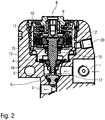
- FIGS 2-4 show different views of a possible structure of the membrane pressure relief valves SLV1, RFV1 and the hardener valve HV, which is also designed as a membrane pressure relief valve.
- the pressure relief valve has an inlet 1 for supplying a fluid (e.g. hardener, base paint) and an outlet 3 for discharging the coating agent.
- a fluid e.g. hardener, base paint
- the flow of the coating agent from the inlet 1 to the outlet 3 is controlled by a needle valve.
- the needle valve has a displaceable valve needle 4, a needle head 5 being screwed onto the distal end of the valve needle 4.
- the needle head 5 is made of titanium and tapers conically towards its end, with an annular groove in which a sealing ring 6 made of FFKM (perfluorinated rubber) is inserted in the conically tapering outer surface of the needle head 5.
- valve seat 7 In the closed position according to Figure 2 If the needle head 5 with the sealing ring 6 rests in a sealing manner on a valve seat 7, the valve seat 7 likewise tapers conically and opens into the outlet 3.
- valve drive 8 which is shown in Figure 3 is shown in detail and works pneumatically.
- the pneumatic valve drive thus has an outer housing insert 9 which is screwed into a housing body 10 of the two-component shut-off valve.
- An inner housing insert 11 is in turn screwed into the outer housing insert 9.
- a piston 12 is arranged displaceably in the pneumatic valve drive 8, the piston 12 being supported by a valve spring 13 in the direction of the closed position according to FIG Figure 1A is biased.
- the valve spring 13 is supported on the outer housing insert 9 and presses at its opposite end against the piston 12 in order to press it into the closed position.
- the piston 12 is connected to the valve needle 4 via a piston insert 14 so that the piston 12 acts on the valve needle 4 and thus also on the needle head.
- the piston 12 is surrounded by a sealing ring 15, which is arranged in the annular gap between the piston 12 on the one hand and the inner wall of the inner housing insert 11 and, when the piston 12 moves, rubs against the inner wall of the inner housing insert 11.
- valve needle 4 runs partially through a valve chamber 17 which is filled with the respective fluid (e.g. hardener, base paint) during operation.
- the respective fluid e.g. hardener, base paint
- a flexible membrane 18 is provided as a sealing element between the valve drive 8 and the media-filled valve chamber 17 in order to seal the valve chamber 17 with respect to the valve drive 8.
- the flexible membrane 18 is sealingly fastened with its outer peripheral edge to the lower end of the inner housing insert 11 and has a central bore through which the valve needle 4 is passed.
- the membrane 18 is fluid-tight and firmly connected to the valve needle 4. On the one hand, the membrane 18 thus takes part in the displacement movement of the valve needle 4 between the closed position and the open position.
- the membrane 4 also seals the media-filled valve chamber 17 from the valve drive 8, whereby no grinding movement is required as is the case with a sealing ring, so that there is also no risk of the low-viscosity and creeping hardener H being able to penetrate the valve drive 8.
- control air which can be introduced into a control air space 19 below the piston 12, the control air in the control air space 19 then pushing the piston 12 upwards.
- the control air is fed into the control air space 19 via a control air connection 20.
- the control air can be provided from a conventional 6-bar compressed air network, which is usually available in paint shops anyway. This offers the advantage that there is no need for a separate compressed air supply can.
- the piston 12 here has a relatively large effective diameter, so that the control air acting on the piston generates a relatively large opening force. When compressed air is applied by the control air, this opening force is greater than the closing force which the valve spring 13 exerts on the piston 12 by a certain excess opening force. In this specific exemplary embodiment, this excess opening force is in the range from 57.4 N to 136 N compared to an excess opening force of only 15 N in a conventional needle valve. This enables the needle head 5 to be “torn loose” from the valve seat 7 even when the needle head 5 adheres to the valve seat 7.
- the conical outer surface of the needle head 5 upstream in front of the sealing ring 6 here forms a support surface 21, which is in the closed position according to FIG Figure 2 is supported on the valve seat 7.
- the support surface 21 forms a stop for the axial movement of the needle head 5 into the closed position. This prevents excessive compression of the sealing ring 6, which is beneficial to the service life of the sealing ring 6.
- the support surface 21 is interrupted here by a plurality of axially running flushing grooves 22 which are arranged distributed over the circumference of the needle head 5.
- the flushing grooves 22 enable in the closed position according to FIG Figure 2 that flushing agent can also reach the area downstream behind the support surface 21 from the inlet 1.
- FIG. 5 shows a modification of Figure 1 so that to avoid repetition, reference is made to the above description, the same reference symbols being used for corresponding details.
- a special feature of this exemplary embodiment is that three strands of coating agent run in the rotary atomizer RZ, namely one strand of coating agent for a hardener, one strand of coating agent for a master paint and one strand of coating agent for a one-component lacquer.
- the coating agent strand for the hardener consists of the line sections L8 and L7.
- the coating agent strand for the base paint on the other hand, consists of line sections L1, L3 and L4.
- the separate line of coating agent for the one-component paint on the other hand, consists of the line section L12.
- the difference compared to the embodiment according to Figure 1 consists essentially in the fact that a separate coating agent strand is provided for the one-component paint, whereas with Figure 1 the coating agent strand consisting of the line sections L1, L12 serves either to supply the base paint or to supply the one-component paint.
- FIG. 6 shows a simplification of Figure 1 so that to avoid repetition, reference is made to the above description, the same reference symbols being used for corresponding details.
- a special feature of this exemplary embodiment is that it is only possible to apply a two-component lacquer, so that only two strands of coating agent are provided in order to apply base lacquer or hardener.
- the coating agent strand for the hardener consists of the line sections L6, L10 and L4.
- the coating agent strand for the main paint on the other hand, consists of the line sections L1, L2, L3 and L4.
- a special feature of this embodiment is that a total of four strands of coating agent run in the rotary atomizer, namely for base paint 1 and hardener 1 of a first two-component paint and for base paint 2 and hardener 2 of a second two-component paint.
- the fluid circuit diagram is therefore essentially in accordance with Figure 4 parallelized and doubled.
- the components for the first two-component paint are opposite Figure 6 with the addition ".1".
- the components for the second two-component paint are opposite Figure 6 with the addition ".2". Otherwise, reference can be made to the description above.
Landscapes
- Nozzles (AREA)
- Coating Apparatus (AREA)
- Spray Control Apparatus (AREA)
- Fluid-Driven Valves (AREA)
- Details Of Valves (AREA)
Claims (15)
- Appareil d'application (RZ), plus particulièrement pulvérisateur rotatif, pour l'application d'un produit de revêtement, plus particulièrement d'une peinture bicomposant, aveca) un premier raccord de produit de revêtement (SL) pour l'alimentation d'un premier produit de revêtement, plus particulièrement d'une peinture de base de la peinture bicomposant,b) un élément d'application, qui applique le produit de revêtement,c) une première canalisation de produit de revêtement (L1 - L4) qui, dans l'appareil d'application (RZ), sort du premier raccord de produit de revêtement (SL) et conduit le premier produit de revêtement vers l'élément d'application etd) une première soupape (SLV1) qui est disposée dans la première canalisation de produit de revêtement (L1 - L4) et qui contrôle le flux du premier produit de revêtement à travers la première canalisation de produit de revêtement (L1 - L4) vers l'élément d'application, dans lequel la première soupape (SLV1) peut être contrôlée par un premier signal de commande,e) dans lequel, dans la première canalisation de produit de revêtement (L1 - L4), est disposée une première soupape de surpression (SLV1) actionnée par son propre fluide, qui s'ouvre automatiquement pour éviter une perturbation de surpression lorsque la pression en amont de la première soupape de surpression (SLV1) dépasse une pression maximale déterminée,
caractérisé en ce quef) la première soupape de surpression (SLV1) est constituée de la première soupape contrôlable (SLV1). - Appareil d'application (RZ) selon l'une des revendications précédentes, caractérisé en ce que, dans la première canalisation de produit de revêtement (L1 - L4), entre la première soupape de surpression (SLV1) et l'élément d'application, est disposée une première soupape principale (HN1), plus particulièrement conçue comme une soupape principale à pointeau, qui arrête ou libère le flux de fluide dans la première canalisation de produit de revêtement (L1 - L4).
- Appareil d'application (RZ) selon la revendication 2,
caractérisé en ce quea) l'appareil d'application (RZ) comprend un deuxième raccord de produit de revêtement (H) pour l'alimentation d'un deuxième produit de revêtement, plus particulièrement d'un durcisseur de la peinture bicomposant,b) du deuxième raccord de produit de revêtement (H) sort une deuxième canalisation de produit de revêtement (L6, L7),c) dans la deuxième canalisation de produit de revêtement (L6, L7), est disposée une deuxième soupape de surpression (HV), qui est actionnée par son propre fluide et qui s'ouvre automatiquement lorsque la pression en amont de la première soupape de surpression dépasse une pression maximale déterminée etd) la deuxième canalisation de produit de revêtement (L6, L7) débouche en amont de la première soupape principale (HN1) dans la première canalisation de produit de revêtement (L1 - L4),e) dans la première canalisation de produit de revêtement (L1 - L4), entre le point d'embouchure de la deuxième canalisation de produit de revêtement (L6, L7) et la première soupape principale (HN1), est disposé de préférence un premier mélangeur (MIX) qui mélange la peinture de base avec le durcisseur afin d'obtenir la peinture bicomposant etf) le premier mélangeur (MIX) est de préférence un mélangeur statique, plus particulièrement un mélangeur à grille ou un mélangeur à spirale. - Appareil d'application (RZ) selon la revendication 2 ou 3,
caractérisé en ce quea) l'appareil d'application (RZ) comprend un premier raccord de retour (RF1) pour le retour des fluides vers un premier retour,b) de la première canalisation de produit de revêtement (L1 - L4), en amont de la première soupape de surpression (SLV1), bifurque une première canalisation de retour,c) la première canalisation de retour débouche dans le premier raccord de retour (RF1) etd) dans la première canalisation de retour est disposée une troisième soupape de surpression (RFV1) qui est actionnée par son propre fluide et qui s'ouvre automatiquement lorsque la pression dans la première canalisation de retour, en amont de la troisième soupape de surpression (RFV1) dépasse une pression maximale déterminée. - Appareil d'application (RZ) selon la revendication 4,
caractérisé en ce quea) l'appareil d'application (RZ) comprend un premier raccord de solvant (VS1) pour l'alimentation d'un premier solvant, plus particulièrement pour la peinture de base,b) du raccord de solvant (VS1) sort une première canalisation de solvant (L11, L10),c) la première canalisation de solvant (L11, L10) débouche dans la première canalisation de produit de revêtement (L1 - L4), entre la première soupape de surpression (SLV1) et la première soupape principale (HN1) etd) dans la première canalisation de solvant (L11, L10), est disposée une première soupape de solvant (VSV1). - Appareil d'application (RZ) selon l'une des revendications précédentes, caractérisé en ce quea) l'appareil d'application (RZ) comprend un raccord d'air pulsé (PL) pour l'alimentation en air pulsé,b) du raccord d'air pulsé (PL) sort une canalisation d'air pulsé (L9, L10),c) la canalisation d'air pulsé (L9, L10) débouche dans la première canalisation de produit de revêtement (L1 - L4), entre la première soupape de surpression (SLV1) et la première soupape principale (HN1) etd) dans la canalisation d'air pulsé (L9, L10) est disposée une soupape d'air pulsé (PLV).
- Appareil d'application (RZ) selon l'une des revendications précédentes, caractérisé en ce quea) l'appareil d'application (RZ) comprend un deuxième raccord de solvant (VH) pour l'alimentation d'un deuxième solvant, plus particulièrement pour le durcisseur,b) du deuxième raccord de solvant (VH) sort une deuxième canalisation de solvant (L8, L7),c) la deuxième canalisation de solvant (L8, L7) débouche dans la première canalisation de produit de revêtement (L1 - L4), entre la première soupape de surpression (SLV1) et la première soupape principale (HN1) etd) dans la deuxième canalisation de solvant (L8, L7) est disposée une deuxième soupape de solvant (VHV1).
- Appareil d'application (RZ) selon l'une des revendications précédentes, caractérisé en ce quea) une troisième canalisation de produit de revêtement (L1, L12) est prévue, qui sort de préférence du premier raccord de produit de revêtement (SL),b) dans la troisième canalisation de produit de revêtement (L1, L12) est disposée une deuxième soupape principale (HN2), plus particulièrement conçue comme une soupape principale à pointeau,c) la première soupape principale (HN1) et la deuxième soupape principale (HN2) sont fusionnées côté sortie et conduisent à l'élément d'application.
- Appareil d'application (RZ) selon la revendication 8,
caractérisé en ce quea) l'appareil d'application (RZ) comprend un deuxième raccord de retour (RF2) pour le retour des fluides vers un deuxième etour,b) de la troisième canalisation de produit de revêtement (L1, L12), en amont de la deuxième soupape principale (HN2), bifurque une deuxième canalisation de retour (L13),c) la deuxième canalisation de retour (L13) débouche dans le deuxième raccord de retour (RF2) etd) dans la deuxième canalisation de retour (L13) est disposée de préférence une soupape de retour (RFV2),e) la soupape de retour (RF2) est de préférence actionnée par son propre fluide,f) la soupape de retour (RF2) différencie, de préférence du fait de sa conception, le produit de revêtement liquide d'une part et l'air comprimé ou la mousse d'autre part,f1) dans lequel la soupape de retour (RF2) s'ouvre lorsque, à l'entrée de la soupape de retour (RF2), se trouve de l'air comprimé ou de la mousse,f2) en revanche, la soupape de retour se ferme lorsque, à l'entrée de la soupape de retour (RF2) se trouve du produit de revêtement liquide. - Appareil d'application (RZ) selon l'une des revendications précédentes, caractérisé en ce quea) l'appareil d'application (RZ) comprend au moins un raccord de rinçage rapide (KS1, KS2) pour l'alimentation d'un produit de rinçage pour un rinçage rapide de l'appareil d'application,b) du raccord de rinçage rapide (KS1, KS2) sort une canalisation de rinçage rapide (L14, L15),c) la canalisation de rinçage rapide (L14, L15) conduit le produit de rinçage vers l'élément d'application en contournant les canalisations de produit de revêtement,d) dans la canalisation de rinçage rapide (L14, L15) est disposée une soupape de rinçage rapide (KSV1, KSV2).
- Appareil d'application (RZ) selon l'une des revendications précédentes, caractérisé en ce que la première soupape de surpression (SLV1), la deuxième soupape de surpression (HV) et/ou la troisième soupape de surpression (RFV1) présentent, dans l'état ouvert, une fonction d'amortissement des coups de bélier, de façon à ce que les coups de bélier survenant du côté de l'entrée ne soient transmis que de manière amortie.
- ppareil d'application (RZ) selon l'une des revendications précédentes, caractérisé en ce que la première soupape de surpression (SLV1), la deuxième soupape de surpression (HV) et/ou la troisième soupape de surpression (RFV1) sont des soupapes à pointeaux aveca) un siège de soupape (7),b) un pointeau de soupape coulissant (4) avec une tige de pointeau et une tête de pointeau (5),b1) dans lequel la tête de pointeau (5) ferme le siège de soupape (7) dans une position de fermeture du pointeau de soupape (4),b2) en revanche, la tête de pointeau (5) libère le siège de soupape (7) dans une position d'ouverture du pointeau de soupape (4),c) une membrane flexible (18) qui entoure de manière annulaire et étanche le pointeau de soupape (4) en amont de la tête de pointeau (5).
- Appareil d'application (RZ) selon la revendication 12,
caractérisé en ce quea) le pointeau de soupape (4) est disposé de manière coulissante dans un espace de soupape (17), dans lequel l'espace de soupape (17) est cylindrique au moins à certains endroits,b) la membrane (18) est fixée au centre de manière étanche à la tige du pointeau de soupape (4) etc) la membrane (18) est fixée, avec son bord circonférentiel, de manière étanche à la paroi interne de l'espace de soupape (17). - Appareil d'application (RZ) selon la revendication 13,
caractérisé para) un entraînement de soupape pour le coulissement du pointeau de soupape (4), plus particulièrement sous la forme d'un entraînement de soupape pneumatique avec un piston (12),b) une entrée de produit de revêtement (1) pour l'alimentation du produit de revêtement, dans lequel l'entrée de produit de revêtement (1) débouche dans l'espace de soupape (17) sur le côté de la membrane (18) opposé à l'entraînement de soupape, de façon à ce que la membrane (18) étanchéifie l'entraînement de soupape par rapport à l'espace de soupape (17) rempli de produit de revêtement etc) une sortie de produit de revêtement (3) pour la distribution du produit de revêtement, dans lequel la sortie de produit de revêtement (3) débouche dans le siège de soupape (7), de façon à ce que le produit de revêtement puisse s'écouler, dans la position d'ouverture du pointeau de soupape (4), à travers le siège de soupape (7) vers la sortie de produit de revêtement (3). - Appareil d'application (RZ) selon la revendication 14, caractérisé en ce que l'entraînement de soupape comprend ce qui suit :a) un piston coulissant (12), qui agit sur le pointeau de soupape (4), afin de faire coulisser le pointeau de soupape (4),b) une entrée d'air de commande (20) pour l'alimentation en air de commande, dans lequel l'air de commande agit sur le piston (12) afin de faire coulisser le piston (12) et donc également le pointeau de soupape (4),c) un ressort de soupape (13) qui agit avec une force élastique sur le piston (12) ou le pointeau de soupape (4),d) la force élastique du ressort de soupape (13) est, dans la position de fermeture et dans la position d'ouverture, de préférence d'au moins 20 N, 40 N ou 80 N et/ou au maximum de 400 N, 200 N ou 100 N.
Priority Applications (1)
| Application Number | Priority Date | Filing Date | Title |
|---|---|---|---|
| PL16735575T PL3317023T3 (pl) | 2015-07-03 | 2016-07-01 | Urządzenie do aplikowania, zwłaszcza rozpylacz rotacyjny |
Applications Claiming Priority (3)
| Application Number | Priority Date | Filing Date | Title |
|---|---|---|---|
| DE102015008658 | 2015-07-03 | ||
| DE102015010158.7A DE102015010158A1 (de) | 2015-07-03 | 2015-08-05 | Applikationsgerät, insbesondere Rotationszerstäuber |
| PCT/EP2016/001126 WO2017005353A1 (fr) | 2015-07-03 | 2016-07-01 | Appareil d'application, en particulier pulvérisateur rotatif |
Publications (2)
| Publication Number | Publication Date |
|---|---|
| EP3317023A1 EP3317023A1 (fr) | 2018-05-09 |
| EP3317023B1 true EP3317023B1 (fr) | 2020-12-30 |
Family
ID=57582706
Family Applications (1)
| Application Number | Title | Priority Date | Filing Date |
|---|---|---|---|
| EP16735575.9A Active EP3317023B1 (fr) | 2015-07-03 | 2016-07-01 | Appareil d'application, en particulier pulvérisateur rotatif |
Country Status (14)
| Country | Link |
|---|---|
| US (2) | US10807110B2 (fr) |
| EP (1) | EP3317023B1 (fr) |
| JP (1) | JP6962905B2 (fr) |
| KR (1) | KR102612208B1 (fr) |
| CN (1) | CN107847951B (fr) |
| BR (1) | BR112017028182B1 (fr) |
| DE (1) | DE102015010158A1 (fr) |
| ES (1) | ES2856681T3 (fr) |
| HU (1) | HUE052424T2 (fr) |
| MX (1) | MX2017016168A (fr) |
| PL (1) | PL3317023T3 (fr) |
| RU (1) | RU2690353C1 (fr) |
| WO (1) | WO2017005353A1 (fr) |
| ZA (1) | ZA201800243B (fr) |
Families Citing this family (4)
| Publication number | Priority date | Publication date | Assignee | Title |
|---|---|---|---|---|
| DE102017122488A1 (de) | 2017-09-27 | 2019-03-28 | Dürr Systems Ag | Applikator mit einer Dichtungsmembran |
| DE102019109208B3 (de) * | 2019-04-08 | 2020-10-01 | Dürr Systems Ag | Applikationseinrichtung und entsprechendes Applikationsverfahren |
| DE102019130612A1 (de) | 2019-11-13 | 2021-05-20 | Dürr Systems Ag | Zerstäuber und zugehöriges Betriebsverfahren |
| TWI807812B (zh) * | 2022-05-06 | 2023-07-01 | 高科晶捷自動化股份有限公司 | 出膠裝置及其出膠方法 |
Citations (1)
| Publication number | Priority date | Publication date | Assignee | Title |
|---|---|---|---|---|
| EP2990124A1 (fr) * | 2014-08-27 | 2016-03-02 | Eisenmann SE | Soupape |
Family Cites Families (33)
| Publication number | Priority date | Publication date | Assignee | Title |
|---|---|---|---|---|
| JPS52153917U (fr) * | 1976-05-19 | 1977-11-22 | ||
| DE2747707C2 (de) | 1977-10-25 | 1982-10-21 | Daimler-Benz Ag, 7000 Stuttgart | Anlage zum Farbspritzen von Serienteilen wechselnder Farbe |
| DE8131967U1 (de) * | 1981-11-02 | 1983-04-07 | J. Wagner AG, 9450 Altstätten | Pumpvorrichtung zum gleichzeitigen zufuehren von zumindest zwei zerstaeubungsfluessigkeiten im waehlbaren mengenverhaeltnis zu einer spritzvorrichtung |
| EP0120848B1 (fr) | 1982-09-30 | 1988-05-11 | Ford Motor Company Limited | Appareil de changement de couleur |
| DE3415253C2 (de) * | 1983-08-12 | 1994-06-30 | Reinhardt Technik Gmbh & Co | Vorrichtung zum Dosieren von einem viskosen Stoff bei niedrigem Anlagedruck |
| DE3713999A1 (de) * | 1987-04-27 | 1988-11-10 | Behr Industrieanlagen | Verfahren zum selbsttaetigen serienweisen beschichten von werkstuecken |
| JP3408722B2 (ja) * | 1997-07-03 | 2003-05-19 | シーケーディ株式会社 | 弁装置 |
| DE29719535U1 (de) * | 1997-11-04 | 1998-02-05 | APSON Lackiertechnik GmbH, 63067 Offenbach | Vielfarb-Lackiereinrichtung |
| US6056270A (en) * | 1998-05-13 | 2000-05-02 | Tri-Clover, Inc. | Valve gasket formed of composite materials and process |
| JP4441960B2 (ja) | 1999-10-04 | 2010-03-31 | 日産自動車株式会社 | 塗料供給装置 |
| US6431521B1 (en) * | 2000-09-21 | 2002-08-13 | Claude Ray Jones | Silicon carbide valve disc for nuclear reactors |
| CN2551350Y (zh) | 2002-04-10 | 2003-05-21 | 台州陆雄农业高新科技有限公司 | 活(柱)塞泵自动泄压装置 |
| DE10335358A1 (de) | 2003-08-01 | 2005-03-10 | Duerr Systems Gmbh | Beschichtungsmittelwechsler |
| US7070066B2 (en) * | 2004-04-08 | 2006-07-04 | Nordson Corporation | Liquid dispensing valve and method with improved stroke length calibration and fluid fittings |
| CN1262352C (zh) * | 2004-06-29 | 2006-07-05 | 深圳市卓宝科技股份有限公司 | 多组份防水涂料全自动喷涂机 |
| DE102006022570A1 (de) | 2006-05-15 | 2007-11-29 | Dürr Systems GmbH | Beschichtungseinrichtung und zugehöriges Betriebsverfahren |
| DE102006053921B4 (de) | 2006-11-15 | 2016-11-24 | Dürr Systems Ag | Lackiermaschine mit einem Zerstäuber und zugehöriges Betriebsverfahren |
| US20080173728A1 (en) * | 2007-01-22 | 2008-07-24 | Patrick Ilfrey | High-solids, reactive components spray application systems |
| DE102007037663A1 (de) * | 2007-08-09 | 2009-02-19 | Dürr Systems GmbH | Nadelventilanordnung |
| DE102008015258B4 (de) * | 2008-03-20 | 2023-05-25 | Dürr Systems Ag | Farbwechsler für einen Lackierroboter |
| DE102008037035B4 (de) | 2008-08-08 | 2023-05-25 | Dürr Systems Ag | Ventilanordnung eines Lackierroboters |
| DE102009020064A1 (de) | 2009-05-06 | 2010-11-11 | Dürr Systems GmbH | Fluidventil, insbesondere Rückführventil für eine Lackieranlage |
| DE102009031180A1 (de) * | 2009-06-29 | 2010-12-30 | Magna Steyr Fahrzeugtechnik Ag & Co Kg | Vorrichtung zur Beschichtung eines Werkstückes |
| DE102010010053B4 (de) * | 2010-03-03 | 2019-05-16 | Dürr Systems Ag | Zerstäuber und Verfahren zum Applizieren von Ein- und Mehr-Komponenten-Beschichtungsmitteln |
| DE102010019771A1 (de) | 2010-05-07 | 2011-11-10 | Dürr Systems GmbH | Zerstäuber mit einem Gittermischer |
| CN202182220U (zh) | 2011-08-25 | 2012-04-04 | 开维喜阀门集团有限公司 | 安全减压阀 |
| CN202209455U (zh) | 2011-09-23 | 2012-05-02 | 福建福思特阀门集团有限公司 | 电动安全泄压持压阀 |
| CN202270502U (zh) | 2011-10-11 | 2012-06-13 | 中国国际海运集装箱(集团)股份有限公司 | 智能调漆系统 |
| DE102013002412A1 (de) | 2013-02-11 | 2014-08-14 | Dürr Systems GmbH | Applikationsverfahren und Applikationsanlage |
| CN203540814U (zh) | 2013-10-24 | 2014-04-16 | 重庆特铺路面工程技术有限公司 | 双组份喷涂系统 |
| CN104174524B (zh) * | 2014-09-16 | 2016-08-24 | 朱红庆 | 一种集装箱油漆自动化智能调漆输送系统及使用方法 |
| CN204422196U (zh) | 2015-03-18 | 2015-06-24 | 北京汽车股份有限公司北京分公司 | 一种涂装机器人雾化器检具 |
| JP7497252B2 (ja) * | 2019-09-02 | 2024-06-10 | エクセル インダストリー | バルブ、このようなバルブを備える被覆体の適用のためのシステム、及び専用の取り付け及び取り外しツール |
-
2015
- 2015-08-05 DE DE102015010158.7A patent/DE102015010158A1/de not_active Withdrawn
-
2016
- 2016-07-01 ES ES16735575T patent/ES2856681T3/es active Active
- 2016-07-01 BR BR112017028182-1A patent/BR112017028182B1/pt active IP Right Grant
- 2016-07-01 US US15/738,584 patent/US10807110B2/en active Active
- 2016-07-01 JP JP2018500327A patent/JP6962905B2/ja active Active
- 2016-07-01 RU RU2018103897A patent/RU2690353C1/ru active
- 2016-07-01 MX MX2017016168A patent/MX2017016168A/es unknown
- 2016-07-01 WO PCT/EP2016/001126 patent/WO2017005353A1/fr active Application Filing
- 2016-07-01 EP EP16735575.9A patent/EP3317023B1/fr active Active
- 2016-07-01 CN CN201680039565.8A patent/CN107847951B/zh active Active
- 2016-07-01 HU HUE16735575A patent/HUE052424T2/hu unknown
- 2016-07-01 KR KR1020187000001A patent/KR102612208B1/ko active IP Right Grant
- 2016-07-01 PL PL16735575T patent/PL3317023T3/pl unknown
-
2018
- 2018-01-12 ZA ZA2018/00243A patent/ZA201800243B/en unknown
-
2020
- 2020-08-12 US US16/991,083 patent/US11623232B2/en active Active
Patent Citations (1)
| Publication number | Priority date | Publication date | Assignee | Title |
|---|---|---|---|---|
| EP2990124A1 (fr) * | 2014-08-27 | 2016-03-02 | Eisenmann SE | Soupape |
Also Published As
| Publication number | Publication date |
|---|---|
| EP3317023A1 (fr) | 2018-05-09 |
| HUE052424T2 (hu) | 2021-04-28 |
| ZA201800243B (en) | 2019-07-31 |
| US11623232B2 (en) | 2023-04-11 |
| MX2017016168A (es) | 2018-04-24 |
| JP6962905B2 (ja) | 2021-11-05 |
| US20200368766A1 (en) | 2020-11-26 |
| US10807110B2 (en) | 2020-10-20 |
| DE102015010158A1 (de) | 2017-01-05 |
| JP2018526197A (ja) | 2018-09-13 |
| WO2017005353A1 (fr) | 2017-01-12 |
| BR112017028182A2 (pt) | 2018-08-28 |
| BR112017028182B1 (pt) | 2021-10-05 |
| CN107847951B (zh) | 2023-05-12 |
| US20180185860A1 (en) | 2018-07-05 |
| PL3317023T3 (pl) | 2021-06-28 |
| CN107847951A (zh) | 2018-03-27 |
| KR102612208B1 (ko) | 2023-12-11 |
| KR20180025884A (ko) | 2018-03-09 |
| RU2690353C1 (ru) | 2019-05-31 |
| ES2856681T3 (es) | 2021-09-28 |
Similar Documents
| Publication | Publication Date | Title |
|---|---|---|
| EP3317570B1 (fr) | Soupape à pointeau | |
| EP3317023B1 (fr) | Appareil d'application, en particulier pulvérisateur rotatif | |
| EP3317003B1 (fr) | Soupape pour agent de revêtement | |
| EP1663504B1 (fr) | Lance de nettoyage | |
| EP0968382B1 (fr) | Soupape a double siege nettoyable | |
| DE69629515T2 (de) | Mischkopf für das Reakionsspritzgiessverfahren mit Vorrichtung zum Spülen mit Lösungsmittel | |
| EP3535063B1 (fr) | Tete d'impression pour appliquer un produit de revêtement sur une piece | |
| DE1498394A1 (de) | Abgabevorrichtung | |
| DE102007037780A1 (de) | Konstantdruckdüse | |
| WO2021259595A1 (fr) | Buse pour distribuer du béton, du mortier ou similaire | |
| DE102007054673B4 (de) | Bandschmiereinrichtung und/oder Reinigungs-Desinfektionsanlage | |
| EP3535064B1 (fr) | Tête d'impression et procédé opérationel correspondant | |
| EP2478967B1 (fr) | Soupape pour un pistolet pulvérisateur, pistolet pulvérisateur et procédé | |
| DE102009020409A1 (de) | Rotordüse | |
| EP2075073B1 (fr) | Système de changement de couleur et procédé de changement de couleur | |
| WO2007134702A1 (fr) | Dispositif de jets en suspension de liquide abrasif | |
| WO2022058105A1 (fr) | Limiteur de débit d'un système d'injection de carburant et système d'injection de carburant comprenant un limiteur de débit | |
| DE10358646A1 (de) | Ventilanordnung zum Mischen eines Mehrkomponenten-Lacks und zugehöriges Betriebsverfahren | |
| EP2876340B1 (fr) | Vanne d'arrêt, notamment pour une installation de peinture | |
| DE202014105124U1 (de) | Dosierpistole | |
| EP3936235A1 (fr) | Installation de revêtement destinée au revêtement de pièces d'une matière de revêtement | |
| DE102006016950B4 (de) | Lackiereinrichtung und Verfahren zum Ausbringen von Lack | |
| DE102009039660A1 (de) | Anlüftbares Sicherheitsventil | |
| DE9410663U1 (de) | Kleinstrahlrohr | |
| DE20000637U1 (de) | Sprühventil |
Legal Events
| Date | Code | Title | Description |
|---|---|---|---|
| STAA | Information on the status of an ep patent application or granted ep patent |
Free format text: STATUS: THE INTERNATIONAL PUBLICATION HAS BEEN MADE |
|
| PUAI | Public reference made under article 153(3) epc to a published international application that has entered the european phase |
Free format text: ORIGINAL CODE: 0009012 |
|
| STAA | Information on the status of an ep patent application or granted ep patent |
Free format text: STATUS: REQUEST FOR EXAMINATION WAS MADE |
|
| 17P | Request for examination filed |
Effective date: 20171206 |
|
| AK | Designated contracting states |
Kind code of ref document: A1 Designated state(s): AL AT BE BG CH CY CZ DE DK EE ES FI FR GB GR HR HU IE IS IT LI LT LU LV MC MK MT NL NO PL PT RO RS SE SI SK SM TR |
|
| AX | Request for extension of the european patent |
Extension state: BA ME |
|
| RIN1 | Information on inventor provided before grant (corrected) |
Inventor name: MICHELFELDER, MANFRED Inventor name: BUCK, THOMAS Inventor name: BAUMANN, MICHAEL Inventor name: HERRE, FRANK Inventor name: SEIZ, BERNHARD Inventor name: HERRMANN, SASCHA |
|
| DAV | Request for validation of the european patent (deleted) | ||
| DAX | Request for extension of the european patent (deleted) | ||
| STAA | Information on the status of an ep patent application or granted ep patent |
Free format text: STATUS: EXAMINATION IS IN PROGRESS |
|
| 17Q | First examination report despatched |
Effective date: 20190506 |
|
| GRAP | Despatch of communication of intention to grant a patent |
Free format text: ORIGINAL CODE: EPIDOSNIGR1 |
|
| GRAJ | Information related to disapproval of communication of intention to grant by the applicant or resumption of examination proceedings by the epo deleted |
Free format text: ORIGINAL CODE: EPIDOSDIGR1 |
|
| GRAP | Despatch of communication of intention to grant a patent |
Free format text: ORIGINAL CODE: EPIDOSNIGR1 |
|
| STAA | Information on the status of an ep patent application or granted ep patent |
Free format text: STATUS: GRANT OF PATENT IS INTENDED |
|
| RIC1 | Information provided on ipc code assigned before grant |
Ipc: B05B 7/04 20060101AFI20200717BHEP Ipc: B05B 12/08 20060101ALI20200717BHEP Ipc: B05B 12/14 20060101ALI20200717BHEP Ipc: B05B 15/55 20180101ALI20200717BHEP Ipc: B05B 1/30 20060101ALI20200717BHEP Ipc: B05B 3/10 20060101ALI20200717BHEP |
|
| INTG | Intention to grant announced |
Effective date: 20200810 |
|
| GRAS | Grant fee paid |
Free format text: ORIGINAL CODE: EPIDOSNIGR3 |
|
| GRAA | (expected) grant |
Free format text: ORIGINAL CODE: 0009210 |
|
| STAA | Information on the status of an ep patent application or granted ep patent |
Free format text: STATUS: THE PATENT HAS BEEN GRANTED |
|
| AK | Designated contracting states |
Kind code of ref document: B1 Designated state(s): AL AT BE BG CH CY CZ DE DK EE ES FI FR GB GR HR HU IE IS IT LI LT LU LV MC MK MT NL NO PL PT RO RS SE SI SK SM TR |
|
| REG | Reference to a national code |
Ref country code: GB Ref legal event code: FG4D Free format text: NOT ENGLISH |
|
| REG | Reference to a national code |
Ref country code: DE Ref legal event code: R096 Ref document number: 502016012083 Country of ref document: DE |
|
| REG | Reference to a national code |
Ref country code: AT Ref legal event code: REF Ref document number: 1349407 Country of ref document: AT Kind code of ref document: T Effective date: 20210115 |
|
| REG | Reference to a national code |
Ref country code: IE Ref legal event code: FG4D Free format text: LANGUAGE OF EP DOCUMENT: GERMAN |
|
| REG | Reference to a national code |
Ref country code: HU Ref legal event code: AG4A Ref document number: E052424 Country of ref document: HU |
|
| PG25 | Lapsed in a contracting state [announced via postgrant information from national office to epo] |
Ref country code: FI Free format text: LAPSE BECAUSE OF FAILURE TO SUBMIT A TRANSLATION OF THE DESCRIPTION OR TO PAY THE FEE WITHIN THE PRESCRIBED TIME-LIMIT Effective date: 20201230 Ref country code: GR Free format text: LAPSE BECAUSE OF FAILURE TO SUBMIT A TRANSLATION OF THE DESCRIPTION OR TO PAY THE FEE WITHIN THE PRESCRIBED TIME-LIMIT Effective date: 20210331 Ref country code: NO Free format text: LAPSE BECAUSE OF FAILURE TO SUBMIT A TRANSLATION OF THE DESCRIPTION OR TO PAY THE FEE WITHIN THE PRESCRIBED TIME-LIMIT Effective date: 20210330 Ref country code: RS Free format text: LAPSE BECAUSE OF FAILURE TO SUBMIT A TRANSLATION OF THE DESCRIPTION OR TO PAY THE FEE WITHIN THE PRESCRIBED TIME-LIMIT Effective date: 20201230 |
|
| REG | Reference to a national code |
Ref country code: SK Ref legal event code: T3 Ref document number: E 36775 Country of ref document: SK |
|
| PG25 | Lapsed in a contracting state [announced via postgrant information from national office to epo] |
Ref country code: SE Free format text: LAPSE BECAUSE OF FAILURE TO SUBMIT A TRANSLATION OF THE DESCRIPTION OR TO PAY THE FEE WITHIN THE PRESCRIBED TIME-LIMIT Effective date: 20201230 Ref country code: BG Free format text: LAPSE BECAUSE OF FAILURE TO SUBMIT A TRANSLATION OF THE DESCRIPTION OR TO PAY THE FEE WITHIN THE PRESCRIBED TIME-LIMIT Effective date: 20210330 Ref country code: LV Free format text: LAPSE BECAUSE OF FAILURE TO SUBMIT A TRANSLATION OF THE DESCRIPTION OR TO PAY THE FEE WITHIN THE PRESCRIBED TIME-LIMIT Effective date: 20201230 |
|
| REG | Reference to a national code |
Ref country code: NL Ref legal event code: MP Effective date: 20201230 |
|
| PG25 | Lapsed in a contracting state [announced via postgrant information from national office to epo] |
Ref country code: HR Free format text: LAPSE BECAUSE OF FAILURE TO SUBMIT A TRANSLATION OF THE DESCRIPTION OR TO PAY THE FEE WITHIN THE PRESCRIBED TIME-LIMIT Effective date: 20201230 |
|
| REG | Reference to a national code |
Ref country code: LT Ref legal event code: MG9D |
|
| PG25 | Lapsed in a contracting state [announced via postgrant information from national office to epo] |
Ref country code: RO Free format text: LAPSE BECAUSE OF FAILURE TO SUBMIT A TRANSLATION OF THE DESCRIPTION OR TO PAY THE FEE WITHIN THE PRESCRIBED TIME-LIMIT Effective date: 20201230 Ref country code: PT Free format text: LAPSE BECAUSE OF FAILURE TO SUBMIT A TRANSLATION OF THE DESCRIPTION OR TO PAY THE FEE WITHIN THE PRESCRIBED TIME-LIMIT Effective date: 20210430 Ref country code: EE Free format text: LAPSE BECAUSE OF FAILURE TO SUBMIT A TRANSLATION OF THE DESCRIPTION OR TO PAY THE FEE WITHIN THE PRESCRIBED TIME-LIMIT Effective date: 20201230 Ref country code: LT Free format text: LAPSE BECAUSE OF FAILURE TO SUBMIT A TRANSLATION OF THE DESCRIPTION OR TO PAY THE FEE WITHIN THE PRESCRIBED TIME-LIMIT Effective date: 20201230 |
|
| REG | Reference to a national code |
Ref country code: ES Ref legal event code: FG2A Ref document number: 2856681 Country of ref document: ES Kind code of ref document: T3 Effective date: 20210928 |
|
| PG25 | Lapsed in a contracting state [announced via postgrant information from national office to epo] |
Ref country code: IS Free format text: LAPSE BECAUSE OF FAILURE TO SUBMIT A TRANSLATION OF THE DESCRIPTION OR TO PAY THE FEE WITHIN THE PRESCRIBED TIME-LIMIT Effective date: 20210430 |
|
| REG | Reference to a national code |
Ref country code: DE Ref legal event code: R097 Ref document number: 502016012083 Country of ref document: DE |
|
| PG25 | Lapsed in a contracting state [announced via postgrant information from national office to epo] |
Ref country code: AL Free format text: LAPSE BECAUSE OF FAILURE TO SUBMIT A TRANSLATION OF THE DESCRIPTION OR TO PAY THE FEE WITHIN THE PRESCRIBED TIME-LIMIT Effective date: 20201230 |
|
| PLBE | No opposition filed within time limit |
Free format text: ORIGINAL CODE: 0009261 |
|
| STAA | Information on the status of an ep patent application or granted ep patent |
Free format text: STATUS: NO OPPOSITION FILED WITHIN TIME LIMIT |
|
| PG25 | Lapsed in a contracting state [announced via postgrant information from national office to epo] |
Ref country code: DK Free format text: LAPSE BECAUSE OF FAILURE TO SUBMIT A TRANSLATION OF THE DESCRIPTION OR TO PAY THE FEE WITHIN THE PRESCRIBED TIME-LIMIT Effective date: 20201230 |
|
| 26N | No opposition filed |
Effective date: 20211001 |
|
| PG25 | Lapsed in a contracting state [announced via postgrant information from national office to epo] |
Ref country code: SI Free format text: LAPSE BECAUSE OF FAILURE TO SUBMIT A TRANSLATION OF THE DESCRIPTION OR TO PAY THE FEE WITHIN THE PRESCRIBED TIME-LIMIT Effective date: 20201230 |
|
| REG | Reference to a national code |
Ref country code: CH Ref legal event code: PL |
|
| PG25 | Lapsed in a contracting state [announced via postgrant information from national office to epo] |
Ref country code: MC Free format text: LAPSE BECAUSE OF FAILURE TO SUBMIT A TRANSLATION OF THE DESCRIPTION OR TO PAY THE FEE WITHIN THE PRESCRIBED TIME-LIMIT Effective date: 20201230 |
|
| REG | Reference to a national code |
Ref country code: BE Ref legal event code: MM Effective date: 20210731 |
|
| PG25 | Lapsed in a contracting state [announced via postgrant information from national office to epo] |
Ref country code: LI Free format text: LAPSE BECAUSE OF NON-PAYMENT OF DUE FEES Effective date: 20210731 Ref country code: CH Free format text: LAPSE BECAUSE OF NON-PAYMENT OF DUE FEES Effective date: 20210731 |
|
| PG25 | Lapsed in a contracting state [announced via postgrant information from national office to epo] |
Ref country code: IS Free format text: LAPSE BECAUSE OF FAILURE TO SUBMIT A TRANSLATION OF THE DESCRIPTION OR TO PAY THE FEE WITHIN THE PRESCRIBED TIME-LIMIT Effective date: 20210430 Ref country code: LU Free format text: LAPSE BECAUSE OF NON-PAYMENT OF DUE FEES Effective date: 20210701 |
|
| PG25 | Lapsed in a contracting state [announced via postgrant information from national office to epo] |
Ref country code: IE Free format text: LAPSE BECAUSE OF NON-PAYMENT OF DUE FEES Effective date: 20210701 Ref country code: BE Free format text: LAPSE BECAUSE OF NON-PAYMENT OF DUE FEES Effective date: 20210731 |
|
| REG | Reference to a national code |
Ref country code: AT Ref legal event code: MM01 Ref document number: 1349407 Country of ref document: AT Kind code of ref document: T Effective date: 20210701 |
|
| PG25 | Lapsed in a contracting state [announced via postgrant information from national office to epo] |
Ref country code: AT Free format text: LAPSE BECAUSE OF NON-PAYMENT OF DUE FEES Effective date: 20210701 |
|
| P01 | Opt-out of the competence of the unified patent court (upc) registered |
Effective date: 20230512 |
|
| PG25 | Lapsed in a contracting state [announced via postgrant information from national office to epo] |
Ref country code: NL Free format text: LAPSE BECAUSE OF NON-PAYMENT OF DUE FEES Effective date: 20201230 Ref country code: CY Free format text: LAPSE BECAUSE OF FAILURE TO SUBMIT A TRANSLATION OF THE DESCRIPTION OR TO PAY THE FEE WITHIN THE PRESCRIBED TIME-LIMIT Effective date: 20201230 |
|
| PG25 | Lapsed in a contracting state [announced via postgrant information from national office to epo] |
Ref country code: SM Free format text: LAPSE BECAUSE OF FAILURE TO SUBMIT A TRANSLATION OF THE DESCRIPTION OR TO PAY THE FEE WITHIN THE PRESCRIBED TIME-LIMIT Effective date: 20201230 |
|
| PGFP | Annual fee paid to national office [announced via postgrant information from national office to epo] |
Ref country code: IT Payment date: 20230720 Year of fee payment: 8 Ref country code: GB Payment date: 20230721 Year of fee payment: 8 Ref country code: ES Payment date: 20230926 Year of fee payment: 8 |
|
| PGFP | Annual fee paid to national office [announced via postgrant information from national office to epo] |
Ref country code: HU Payment date: 20230721 Year of fee payment: 8 Ref country code: FR Payment date: 20230726 Year of fee payment: 8 Ref country code: DE Payment date: 20230719 Year of fee payment: 8 |
|
| PG25 | Lapsed in a contracting state [announced via postgrant information from national office to epo] |
Ref country code: MK Free format text: LAPSE BECAUSE OF FAILURE TO SUBMIT A TRANSLATION OF THE DESCRIPTION OR TO PAY THE FEE WITHIN THE PRESCRIBED TIME-LIMIT Effective date: 20201230 |
|
| PGFP | Annual fee paid to national office [announced via postgrant information from national office to epo] |
Ref country code: CZ Payment date: 20240624 Year of fee payment: 9 |
|
| PGFP | Annual fee paid to national office [announced via postgrant information from national office to epo] |
Ref country code: SK Payment date: 20240626 Year of fee payment: 9 |
|
| PGFP | Annual fee paid to national office [announced via postgrant information from national office to epo] |
Ref country code: PL Payment date: 20240621 Year of fee payment: 9 |
|
| PGFP | Annual fee paid to national office [announced via postgrant information from national office to epo] |
Ref country code: TR Payment date: 20240624 Year of fee payment: 9 |