EP2990124A1 - Soupape - Google Patents
Soupape Download PDFInfo
- Publication number
- EP2990124A1 EP2990124A1 EP15002401.6A EP15002401A EP2990124A1 EP 2990124 A1 EP2990124 A1 EP 2990124A1 EP 15002401 A EP15002401 A EP 15002401A EP 2990124 A1 EP2990124 A1 EP 2990124A1
- Authority
- EP
- European Patent Office
- Prior art keywords
- valve
- valve seat
- sealing element
- seat sealing
- housing
- Prior art date
- Legal status (The legal status is an assumption and is not a legal conclusion. Google has not performed a legal analysis and makes no representation as to the accuracy of the status listed.)
- Withdrawn
Links
Images

Classifications
-
- B—PERFORMING OPERATIONS; TRANSPORTING
- B05—SPRAYING OR ATOMISING IN GENERAL; APPLYING FLUENT MATERIALS TO SURFACES, IN GENERAL
- B05B—SPRAYING APPARATUS; ATOMISING APPARATUS; NOZZLES
- B05B12/00—Arrangements for controlling delivery; Arrangements for controlling the spray area
- B05B12/14—Arrangements for controlling delivery; Arrangements for controlling the spray area for supplying a selected one of a plurality of liquids or other fluent materials or several in selected proportions to a spray apparatus, e.g. to a single spray outlet
- B05B12/149—Arrangements for controlling delivery; Arrangements for controlling the spray area for supplying a selected one of a plurality of liquids or other fluent materials or several in selected proportions to a spray apparatus, e.g. to a single spray outlet characterised by colour change manifolds or valves therefor
-
- B—PERFORMING OPERATIONS; TRANSPORTING
- B05—SPRAYING OR ATOMISING IN GENERAL; APPLYING FLUENT MATERIALS TO SURFACES, IN GENERAL
- B05B—SPRAYING APPARATUS; ATOMISING APPARATUS; NOZZLES
- B05B1/00—Nozzles, spray heads or other outlets, with or without auxiliary devices such as valves, heating means
- B05B1/14—Nozzles, spray heads or other outlets, with or without auxiliary devices such as valves, heating means with multiple outlet openings; with strainers in or outside the outlet opening
- B05B1/16—Nozzles, spray heads or other outlets, with or without auxiliary devices such as valves, heating means with multiple outlet openings; with strainers in or outside the outlet opening having selectively- effective outlets
- B05B1/1609—Nozzles, spray heads or other outlets, with or without auxiliary devices such as valves, heating means with multiple outlet openings; with strainers in or outside the outlet opening having selectively- effective outlets with a selecting mechanism comprising a lift valve
- B05B1/1618—Nozzles, spray heads or other outlets, with or without auxiliary devices such as valves, heating means with multiple outlet openings; with strainers in or outside the outlet opening having selectively- effective outlets with a selecting mechanism comprising a lift valve where said valve is a double-seat lift valve
-
- B—PERFORMING OPERATIONS; TRANSPORTING
- B05—SPRAYING OR ATOMISING IN GENERAL; APPLYING FLUENT MATERIALS TO SURFACES, IN GENERAL
- B05B—SPRAYING APPARATUS; ATOMISING APPARATUS; NOZZLES
- B05B1/00—Nozzles, spray heads or other outlets, with or without auxiliary devices such as valves, heating means
- B05B1/30—Nozzles, spray heads or other outlets, with or without auxiliary devices such as valves, heating means designed to control volume of flow, e.g. with adjustable passages
- B05B1/3013—Nozzles, spray heads or other outlets, with or without auxiliary devices such as valves, heating means designed to control volume of flow, e.g. with adjustable passages the controlling element being a lift valve
-
- F—MECHANICAL ENGINEERING; LIGHTING; HEATING; WEAPONS; BLASTING
- F16—ENGINEERING ELEMENTS AND UNITS; GENERAL MEASURES FOR PRODUCING AND MAINTAINING EFFECTIVE FUNCTIONING OF MACHINES OR INSTALLATIONS; THERMAL INSULATION IN GENERAL
- F16K—VALVES; TAPS; COCKS; ACTUATING-FLOATS; DEVICES FOR VENTING OR AERATING
- F16K1/00—Lift valves or globe valves, i.e. cut-off apparatus with closure members having at least a component of their opening and closing motion perpendicular to the closing faces
- F16K1/32—Details
- F16K1/34—Cutting-off parts, e.g. valve members, seats
- F16K1/36—Valve members
- F16K1/38—Valve members of conical shape
-
- F—MECHANICAL ENGINEERING; LIGHTING; HEATING; WEAPONS; BLASTING
- F16—ENGINEERING ELEMENTS AND UNITS; GENERAL MEASURES FOR PRODUCING AND MAINTAINING EFFECTIVE FUNCTIONING OF MACHINES OR INSTALLATIONS; THERMAL INSULATION IN GENERAL
- F16K—VALVES; TAPS; COCKS; ACTUATING-FLOATS; DEVICES FOR VENTING OR AERATING
- F16K31/00—Actuating devices; Operating means; Releasing devices
- F16K31/12—Actuating devices; Operating means; Releasing devices actuated by fluid
- F16K31/122—Actuating devices; Operating means; Releasing devices actuated by fluid the fluid acting on a piston
- F16K31/1221—Actuating devices; Operating means; Releasing devices actuated by fluid the fluid acting on a piston one side of the piston being spring-loaded
-
- F—MECHANICAL ENGINEERING; LIGHTING; HEATING; WEAPONS; BLASTING
- F16—ENGINEERING ELEMENTS AND UNITS; GENERAL MEASURES FOR PRODUCING AND MAINTAINING EFFECTIVE FUNCTIONING OF MACHINES OR INSTALLATIONS; THERMAL INSULATION IN GENERAL
- F16K—VALVES; TAPS; COCKS; ACTUATING-FLOATS; DEVICES FOR VENTING OR AERATING
- F16K41/00—Spindle sealings
- F16K41/10—Spindle sealings with diaphragm, e.g. shaped as bellows or tube
- F16K41/103—Spindle sealings with diaphragm, e.g. shaped as bellows or tube the diaphragm and the closure member being integrated in one member
Definitions
- Valves of the type mentioned are as needle valves, for example, from DE 10 2006 025 549 A1 are known and used in coating systems for controlling the flow of coating material.
- the sealing element of the valve cooperates with a valve seat, which it closes or releases when the valve stem in the valve housing assumes its closed position or its release position.
- the valve must sit in a conventional manner in a suitable valve seat, which dictates the valve seat.
- the valve receptacle is located, for example, in a valve receiving assembly, such as a so-called color changer.
- the valve spindle As a rule, it assumes its closed position under prestress. In the closed position, the valve seat sealing element assumes a position in which it seals against the existing valve seat and closes it.
- Switching between the closed position and the release position of the valve stem is effected in known valves, for example by means of a pressurized fluid in the form of compressed air.
- a piston element is displaced on the valve spindle in the interior of the housing by supplying compressed air into a piston chamber against a spring to open the valve.
- the passage opening in the housing serves to guide the valve spindle.
- seals are required, which seal the piston chamber against a feed space on the other side of the seal, which is flowed through when the valve is open by the medium to be conveyed.
- sealing elements are provided, which rest with an annular sealing edge on the valve stem and strip the lifting of the valve spindle adhering to her lacquer material or other media.
- critical coating media such as the hardener component of 2K paints, in particular isocyanate, are pulled by the lifting movement of the valve stem under the sealing edge and then cured by a chemical reaction with moisture, which also leads to malfunction of the valve.
- critical coating media such as the hardener component of 2K paints, in particular isocyanate
- a needle valve of the type mentioned, in particular a Needle valve, in which already an improved sealing effect is made possible, is from the DE 10 2007 037 663 A1 known.
- a ring-shaped sealing membrane is used as a valve spindle seal, which is immovably connected along its inner contour with the valve stem and movable with it and connects along its outer contour to the valve housing.
- the attachment of the sealing membrane to the valve stem is associated with higher production costs and with greater technical challenges regarding the sealing effect.
- due to a remaining minimum annular gap at the joint between the valve stem and the sealing membrane there may be adverse effects and even leakage, despite the lack of (macroscopic) relative movement between the valve stem and the sealing membrane.
- valve spindle never comes into contact with the medium to be conveyed. Between the diaphragm collar and the valve housing a kind of dead space is formed, in which the valve spindle extends.
- the membrane collar is part of a sealing member with a support portion, wherein the support portion at least partially covers the valve seat sealing member and carries the membrane collar.
- a sealing member can be manufactured as an independent component, and, for example, cap-like placed on the valve seat sealing element, which allows a simplified assembly and, where appropriate, an exchange of an impaired sealing member.
- an integral connection stands for an inseparable connection, which was produced, for example, by material connection and which only allows the blank to form the membrane collar.
- the support section is integrally connected to the valve seat sealing element. As a result, lifting and releasing of the support portion is prevented by the sealing element.
- valve seat sealing element and the membrane collar can be made of the same material.
- a support section made of a different material may nevertheless be effective. For example, this may be the case when an increased load bearing capacity is desired for the support element in contact with a valve seat of a separate unit.
- valve seat sealing element and the sealing member are made of the same material.
- the membrane collar is made of a flexible elastic material.
- a flexible anelastic material may be used.
- the membrane collar is made of a plastic.
- valves have been established in practice in which the plastic is polytetrafluoroethylene (PTFE).
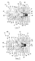
- a valve which is designed as a needle valve 12 and by means of a pressurized fluid, in particular by means of compressed air, can be actuated.
- the needle valve 12 comprises a multi-part valve housing 14 with a substantially cylindrical hollow housing body 16, which is frontally frusto-conical shaped in the present embodiment, and a housing cover 18, which are arranged coaxially with each other.
- the housing body 16 and the housing cover 18 are connected to each other via not specially marked latching or screw connections.
- the valve housing 14 defines a piston chamber 20.
- a control channel 22 penetrates the housing body 16 in the radial direction and opens into the piston chamber 20, so that the supply of the pressurized fluid into the piston chamber 20 is made possible.
- the housing body 16 On the side facing away from the housing cover 18 end face the housing body 16 has a coaxial passage opening 24, which opens into the piston chamber 20 and extends coaxially thereto.
- the passage opening 24 is bounded by a circular-cylindrical guide surface 26, which guides a displaceably mounted valve spindle 28.
- valve spindle 28 has a spring receiving portion 30 which projects into a cylindrical compression spring 32, which is supported in the piston chamber 20 on the housing cover 18.
- compression spring 32 By the compression spring 32, the valve stem 28 is pressed under spring bias in a closed position in which the valve stem 32 is further extended from the valve housing 12 as in a release position.
- the spring receiving portion 30 is dimensioned such that a necessary to achieve the release position travel is guaranteed.
- a circumferentially radially projecting piston member 34 connects, which is immovably encompassed by the valve stem 28 and on which engages the compression spring 32 with its end remote from the housing cover end.
- the piston member 34 is located in the piston chamber 20 and has an extension in the axial direction, which is shorter than the length of the piston chamber 20 in this direction.
- the piston element 34 is followed by a guide section 36 of the valve spindle 28, which runs on the complementary guide surface 26 of the passage opening 24 in the housing body 14.
- the piston member 34 carries in the circumferential direction a not-shown sealing ring which seals the piston member 34 against the inner wall of the piston chamber 20.
- a ring seal 38 is present, which seals the piston chamber 20 to the outside and there prevents the escape of the pressurized fluid.
- the valve spindle 28 carries at a spindle head end 40 a valve seat sealing element 42. This is locked, for example via a latching portion by plugging on the valve stem 28, as it is in itself known.
- valve seat sealing element 42 for example, in the case of a metallic valve seat sealing element by means of a press fit, or in the case of a valve seat sealing element made of a ceramic or a plastic by means of an adhesive bond to the spindle head end 40 to be attached.
- the valve seat sealing member 42 includes a connecting portion 44 in contact with the valve stem 28, a body portion 46 configured to be substantially circular cylindrical, and a frusto-conical seat portion 48 formed at the free head end of the valve seat sealing member 42.
- the valve seat sealing element 42 carries a sealing member 50, which comprises a support portion 52 and a diaphragm collar 54.
- the support portion 52 follows the shape of the valve seat sealing member 42 and covers the seat portion 48 and the body portion 46 on the entire circumference tightly.
- material recesses not shown specifically in the support section 52 are also conceivable here, wherein the seat section 48 is excluded from such recesses.
- webs may be formed on the periphery of the body portion 46 of the valve seat sealing member 42 connecting the support portion 52 on the seat portion 48 with the diaphragm collar 54 which is supported on the connecting portion 44 of the valve seat sealing member 42 and integrally connected thereto.
- the described needle valve 14 can be installed, for example, in a valve receptacle 56 of an exchange unit 58, which is part of a coating system 60, of which only a detail is shown in the figures.
- a feed channel 62 Via a feed channel 62, the medium to be conveyed, for example paint or hardener, a feed space 64 of the exchange unit 58 is supplied.
- a discharge channel 66 is connected via a valve seat 68 to the feed space 64 and passes the medium to be conveyed, for example, to an application device.
- valve spindle 28 In its closed position, the valve spindle 28 is extended by the spring force of the compression spring 32 so far out of the valve housing 14 that the valve seat sealing element 42 is pressed into the valve seat 68 of the exchange unit 58, so that it is sealed.
- Contact surfaces of the valve seat sealing element 42 and the valve seat 68 are complementary to one another in order to achieve an optimum sealing effect. In the present embodiment, such contact surfaces are conical.
- the contact surface shape of the seat portion 48 of the valve seat sealing member 42 in this case supports the power transmission to the support portion 52 and thus helps to secure seal in the closed configuration of Needle Valve 12.
- the contact can be made only via the seat portion 48 of the valve seat sealing member 42.
- the diaphragm collar 54 has a seal member portion 72 abutting and integrally connected to the connecting portion 44 of the valve seat seal member 42, a holding portion 74, and a free diaphragm portion 76 extending therebetween.
- the holding portion 74 is formed complementary to a retaining shoulder 78 of the valve housing 14, via which the holding portion 74 is connected to the valve housing 14.
- the connection may be intrinsically inextricable, for example by means of gluing. Alternatively, the connection can also be made detachably, for example by plugging.
- the membrane section 76 as a connecting piece between the sealing element section 72 and the housing section 74, fulfills the actual function of sealing the passage opening 24 against the outside environment of the valve 10.
- valve spindle 28 moves away from the valve seat 68 and the needle valve 12 moves into the in FIG. 2 over the release configuration shown.
- the membrane section 76 can fold and a corresponding shaft 80 can partially into a receiving lip 82nd of the valve housing 14 to enter.
- the complete sealing member 50 but in particular at least the membrane collar 76 is made of a flexible plastic, which may be elastic or anelastic.
- the membrane section 76 is designed so that it is not loaded in the closed position to train, so that a higher component fatigue strength is ensured.
- a flexible plastic is provided, wherein polytetrafluoroethylene (PTFE) is particularly advantageous. But other fluorine-containing plastics are suitable here.
- perfluoroethylene-propylene FEP perfluoroalkoxyalkanes PFA
- polyvinylidene fluoride PVDF polyvinylidene fluoride PVDF or else fluorine-containing elastomers and also generally crosslinked elastomers are suitable.
- FIGS. 3 and 4 is shown as a second embodiment, a needle valve 12, in which the valve seat sealing element 42 and the sealing member 50 as a single component in the form of a sealing body 84, are executed.
- sealing body 84 can be kept low with a suitable choice of material manufacturing and assembly costs.
- polytetrafluoroethylene (PTFE) has proven itself as a material here as well.
- a corresponding sealing body 84 of PTFE has sufficient rigidity to ensure the desired sealing effect of the needle valve 12 and sufficient flexibility to form the diaphragm collar 54 according to the specifications.
Landscapes
- Engineering & Computer Science (AREA)
- General Engineering & Computer Science (AREA)
- Mechanical Engineering (AREA)
- Lift Valve (AREA)
Applications Claiming Priority (1)
| Application Number | Priority Date | Filing Date | Title |
|---|---|---|---|
| DE102014012705.2A DE102014012705A1 (de) | 2014-08-27 | 2014-08-27 | Ventil |
Publications (1)
| Publication Number | Publication Date |
|---|---|
| EP2990124A1 true EP2990124A1 (fr) | 2016-03-02 |
Family
ID=53836353
Family Applications (1)
| Application Number | Title | Priority Date | Filing Date |
|---|---|---|---|
| EP15002401.6A Withdrawn EP2990124A1 (fr) | 2014-08-27 | 2015-08-13 | Soupape |
Country Status (2)
| Country | Link |
|---|---|
| EP (1) | EP2990124A1 (fr) |
| DE (1) | DE102014012705A1 (fr) |
Cited By (1)
| Publication number | Priority date | Publication date | Assignee | Title |
|---|---|---|---|---|
| US10807110B2 (en) | 2015-07-03 | 2020-10-20 | Dürr Systems Ag | Applicator, in particular rotary atomiser |
Families Citing this family (13)
| Publication number | Priority date | Publication date | Assignee | Title |
|---|---|---|---|---|
| DE102015008661A1 (de) | 2015-07-03 | 2017-01-05 | Dürr Systems Ag | Nadelventil |
| DE102015008659B4 (de) | 2015-07-03 | 2019-06-19 | Dürr Systems Ag | Beschichtungsmittelventil und Rotationszerstäuber |
| DE102016014955A1 (de) | 2016-12-14 | 2018-06-14 | Dürr Systems Ag | Beschichtungseinrichtung und entsprechendes Beschichtungsverfahren |
| DE102016014948A1 (de) | 2016-12-14 | 2018-06-14 | Dürr Systems Ag | Druckkopf und zugehöriges Betriebsverfahren |
| DE102016014946A1 (de) | 2016-12-14 | 2018-06-14 | Dürr Systems Ag | Druckkopf zur Applikation eines Beschichtungsmittels auf ein Bauteil |
| DE102016014943A1 (de) | 2016-12-14 | 2018-06-14 | Dürr Systems Ag | Druckkopf mit Temperiereinrichtung |
| DE102016014919A1 (de) | 2016-12-14 | 2018-06-14 | Dürr Systems Ag | Applikationsvorrichtung und Verfahren zum Applizieren eines Beschichtungsmittels |
| DE102016014947A1 (de) * | 2016-12-14 | 2018-06-14 | Dürr Systems Ag | Druckkopf zur Applikation eines Beschichtungsmittels |
| DE102016014956A1 (de) | 2016-12-14 | 2018-06-14 | Dürr Systems Ag | Beschichtungseinrichtung und zugehöriges Betriebsverfahren |
| DE102016014953A1 (de) | 2016-12-14 | 2018-06-14 | Dürr Systems Ag | Lackieranlage und entsprechendes Lackierverfahren |
| DE102016014952A1 (de) | 2016-12-14 | 2018-06-14 | Dürr Systems Ag | Beschichtungseinrichtung zur Beschichtung von Bauteilen |
| DE102016014951A1 (de) | 2016-12-14 | 2018-06-14 | Dürr Systems Ag | Beschichtungseinrichtung und zugehöriges Betriebsverfahren |
| DE102016014944A1 (de) | 2016-12-14 | 2018-06-14 | Dürr Systems Ag | Beschichtungsverfahren und entsprechende Beschichtungseinrichtung |
Citations (7)
| Publication number | Priority date | Publication date | Assignee | Title |
|---|---|---|---|---|
| JPH061961U (ja) * | 1992-06-18 | 1994-01-14 | 旭有機材工業株式会社 | 調節弁 |
| WO1999053231A1 (fr) * | 1998-04-11 | 1999-10-21 | Tuchenhagen Gmbh | Soufflet destine a l'etancheite d'un passage de tige de soupape d'une soupape de levee |
| WO2002048587A1 (fr) * | 2000-12-13 | 2002-06-20 | Abb K. K. | Soupape d'arret pour peinture |
| WO2004013524A1 (fr) * | 2002-08-06 | 2004-02-12 | Fedegari Autoclavi Spa | Obturateur sanitaire a diaphragme |
| DE102005033191A1 (de) * | 2004-07-16 | 2006-02-16 | Smc K.K. | Farbauswahlventil |
| DE102006025549A1 (de) | 2006-06-01 | 2007-12-06 | Eisenmann Lacktechnik Gmbh & Co. Kg | Ventil |
| DE102007037663A1 (de) | 2007-08-09 | 2009-02-19 | Dürr Systems GmbH | Nadelventilanordnung |
Family Cites Families (3)
| Publication number | Priority date | Publication date | Assignee | Title |
|---|---|---|---|---|
| DE902924C (de) * | 1952-03-29 | 1954-01-28 | Schneider Bochumer Maschf A | Stulpenventil |
| DE1084996B (de) * | 1954-07-27 | 1960-07-07 | Rheinisches Metallwerk Gmbh | Absperrschieber mit einem Verschlussstueck, das mit einem UEberzug aus Gummi versehen ist |
| JP4310532B2 (ja) * | 2002-11-27 | 2009-08-12 | Smc株式会社 | 流量調整弁 |
-
2014
- 2014-08-27 DE DE102014012705.2A patent/DE102014012705A1/de not_active Ceased
-
2015
- 2015-08-13 EP EP15002401.6A patent/EP2990124A1/fr not_active Withdrawn
Patent Citations (7)
| Publication number | Priority date | Publication date | Assignee | Title |
|---|---|---|---|---|
| JPH061961U (ja) * | 1992-06-18 | 1994-01-14 | 旭有機材工業株式会社 | 調節弁 |
| WO1999053231A1 (fr) * | 1998-04-11 | 1999-10-21 | Tuchenhagen Gmbh | Soufflet destine a l'etancheite d'un passage de tige de soupape d'une soupape de levee |
| WO2002048587A1 (fr) * | 2000-12-13 | 2002-06-20 | Abb K. K. | Soupape d'arret pour peinture |
| WO2004013524A1 (fr) * | 2002-08-06 | 2004-02-12 | Fedegari Autoclavi Spa | Obturateur sanitaire a diaphragme |
| DE102005033191A1 (de) * | 2004-07-16 | 2006-02-16 | Smc K.K. | Farbauswahlventil |
| DE102006025549A1 (de) | 2006-06-01 | 2007-12-06 | Eisenmann Lacktechnik Gmbh & Co. Kg | Ventil |
| DE102007037663A1 (de) | 2007-08-09 | 2009-02-19 | Dürr Systems GmbH | Nadelventilanordnung |
Cited By (3)
| Publication number | Priority date | Publication date | Assignee | Title |
|---|---|---|---|---|
| US10807110B2 (en) | 2015-07-03 | 2020-10-20 | Dürr Systems Ag | Applicator, in particular rotary atomiser |
| EP3317023B1 (fr) * | 2015-07-03 | 2020-12-30 | Dürr Systems AG | Appareil d'application, en particulier pulvérisateur rotatif |
| US11623232B2 (en) | 2015-07-03 | 2023-04-11 | Dürr Systems Ag | Applicator, in particular rotary atomiser |
Also Published As
| Publication number | Publication date |
|---|---|
| DE102014012705A1 (de) | 2016-03-17 |
Similar Documents
| Publication | Publication Date | Title |
|---|---|---|
| EP2990124A1 (fr) | Soupape | |
| DE102007037663A1 (de) | Nadelventilanordnung | |
| EP3090196A1 (fr) | Soupape | |
| EP2397727B1 (fr) | Tête de soupape en plusieurs parties | |
| EP3478969B1 (fr) | Cylindre émetteur, en particulier pour un dispositif hydraulique d'actionnement d'embrayage dans des véhicules | |
| DE102008044819A1 (de) | Hydraulisches Element | |
| EP3317003B1 (fr) | Soupape pour agent de revêtement | |
| EP2213850B1 (fr) | Agencement d'étanchéification pour un tiroir rotatif | |
| EP3317570B1 (fr) | Soupape à pointeau | |
| EP2855943A1 (fr) | Maître-cylindre | |
| DE102014004668A1 (de) | Ventil | |
| EP2833042B1 (fr) | Agencement de soupape destiné à commuter et/ou régler un flux de milieu d'un propulseur spatial et propulseur spatial | |
| EP2924327B1 (fr) | Vanne multi-voies | |
| DE102014013992A1 (de) | Kolben eines fluidbetätigten Linearantriebes und zugehöriger Linearantrieb | |
| DE102006022212A1 (de) | Federanordnung | |
| WO2017174064A1 (fr) | Garniture d'étanchéité pour ensemble cylindre-piston | |
| DE102009021902A1 (de) | Nehmerzylinderanordnung | |
| AT394764B (de) | Hydraulischer druckuebersetzer | |
| WO2020187673A1 (fr) | Dispositif de soupape | |
| EP1703185A1 (fr) | Soupape coaxiale | |
| DE102014216619A1 (de) | Nehmerzylinder zur Betätigung einer Kupplung, Kupplung für ein Kraftfahrzeug und Kraftfahrzeug mit entsprechender Kupplung | |
| DE102019120227A1 (de) | Ventil und Vorrichtung zur Regelung von Drücken eines Strömungsmittels mit dem Ventil sowie Vorrichtung zur Sicherung des Ventils in dem Getriebebauteil | |
| DE102016103958A1 (de) | Pilotgesteuertes Sicherheitsventil | |
| EP2990280B1 (fr) | Système doté d'une conduite fluidique et tête de couplage | |
| DE102015212753A1 (de) | Ventilantrieb |
Legal Events
| Date | Code | Title | Description |
|---|---|---|---|
| PUAI | Public reference made under article 153(3) epc to a published international application that has entered the european phase |
Free format text: ORIGINAL CODE: 0009012 |
|
| AK | Designated contracting states |
Kind code of ref document: A1 Designated state(s): AL AT BE BG CH CY CZ DE DK EE ES FI FR GB GR HR HU IE IS IT LI LT LU LV MC MK MT NL NO PL PT RO RS SE SI SK SM TR |
|
| AX | Request for extension of the european patent |
Extension state: BA ME |
|
| STAA | Information on the status of an ep patent application or granted ep patent |
Free format text: STATUS: THE APPLICATION IS DEEMED TO BE WITHDRAWN |
|
| 18D | Application deemed to be withdrawn |
Effective date: 20160903 |