EP2990124A1 - Valve - Google Patents
Valve Download PDFInfo
- Publication number
- EP2990124A1 EP2990124A1 EP15002401.6A EP15002401A EP2990124A1 EP 2990124 A1 EP2990124 A1 EP 2990124A1 EP 15002401 A EP15002401 A EP 15002401A EP 2990124 A1 EP2990124 A1 EP 2990124A1
- Authority
- EP
- European Patent Office
- Prior art keywords
- valve
- valve seat
- sealing element
- seat sealing
- housing
- Prior art date
- Legal status (The legal status is an assumption and is not a legal conclusion. Google has not performed a legal analysis and makes no representation as to the accuracy of the status listed.)
- Withdrawn
Links
Images

Classifications
-
- B—PERFORMING OPERATIONS; TRANSPORTING
- B05—SPRAYING OR ATOMISING IN GENERAL; APPLYING FLUENT MATERIALS TO SURFACES, IN GENERAL
- B05B—SPRAYING APPARATUS; ATOMISING APPARATUS; NOZZLES
- B05B12/00—Arrangements for controlling delivery; Arrangements for controlling the spray area
- B05B12/14—Arrangements for controlling delivery; Arrangements for controlling the spray area for supplying a selected one of a plurality of liquids or other fluent materials or several in selected proportions to a spray apparatus, e.g. to a single spray outlet
- B05B12/149—Arrangements for controlling delivery; Arrangements for controlling the spray area for supplying a selected one of a plurality of liquids or other fluent materials or several in selected proportions to a spray apparatus, e.g. to a single spray outlet characterised by colour change manifolds or valves therefor
-
- B—PERFORMING OPERATIONS; TRANSPORTING
- B05—SPRAYING OR ATOMISING IN GENERAL; APPLYING FLUENT MATERIALS TO SURFACES, IN GENERAL
- B05B—SPRAYING APPARATUS; ATOMISING APPARATUS; NOZZLES
- B05B1/00—Nozzles, spray heads or other outlets, with or without auxiliary devices such as valves, heating means
- B05B1/14—Nozzles, spray heads or other outlets, with or without auxiliary devices such as valves, heating means with multiple outlet openings; with strainers in or outside the outlet opening
- B05B1/16—Nozzles, spray heads or other outlets, with or without auxiliary devices such as valves, heating means with multiple outlet openings; with strainers in or outside the outlet opening having selectively- effective outlets
- B05B1/1609—Nozzles, spray heads or other outlets, with or without auxiliary devices such as valves, heating means with multiple outlet openings; with strainers in or outside the outlet opening having selectively- effective outlets with a selecting mechanism comprising a lift valve
- B05B1/1618—Nozzles, spray heads or other outlets, with or without auxiliary devices such as valves, heating means with multiple outlet openings; with strainers in or outside the outlet opening having selectively- effective outlets with a selecting mechanism comprising a lift valve where said valve is a double-seat lift valve
-
- B—PERFORMING OPERATIONS; TRANSPORTING
- B05—SPRAYING OR ATOMISING IN GENERAL; APPLYING FLUENT MATERIALS TO SURFACES, IN GENERAL
- B05B—SPRAYING APPARATUS; ATOMISING APPARATUS; NOZZLES
- B05B1/00—Nozzles, spray heads or other outlets, with or without auxiliary devices such as valves, heating means
- B05B1/30—Nozzles, spray heads or other outlets, with or without auxiliary devices such as valves, heating means designed to control volume of flow, e.g. with adjustable passages
- B05B1/3013—Nozzles, spray heads or other outlets, with or without auxiliary devices such as valves, heating means designed to control volume of flow, e.g. with adjustable passages the controlling element being a lift valve
-
- F—MECHANICAL ENGINEERING; LIGHTING; HEATING; WEAPONS; BLASTING
- F16—ENGINEERING ELEMENTS AND UNITS; GENERAL MEASURES FOR PRODUCING AND MAINTAINING EFFECTIVE FUNCTIONING OF MACHINES OR INSTALLATIONS; THERMAL INSULATION IN GENERAL
- F16K—VALVES; TAPS; COCKS; ACTUATING-FLOATS; DEVICES FOR VENTING OR AERATING
- F16K1/00—Lift valves or globe valves, i.e. cut-off apparatus with closure members having at least a component of their opening and closing motion perpendicular to the closing faces
- F16K1/32—Details
- F16K1/34—Cutting-off parts, e.g. valve members, seats
- F16K1/36—Valve members
- F16K1/38—Valve members of conical shape
-
- F—MECHANICAL ENGINEERING; LIGHTING; HEATING; WEAPONS; BLASTING
- F16—ENGINEERING ELEMENTS AND UNITS; GENERAL MEASURES FOR PRODUCING AND MAINTAINING EFFECTIVE FUNCTIONING OF MACHINES OR INSTALLATIONS; THERMAL INSULATION IN GENERAL
- F16K—VALVES; TAPS; COCKS; ACTUATING-FLOATS; DEVICES FOR VENTING OR AERATING
- F16K31/00—Actuating devices; Operating means; Releasing devices
- F16K31/12—Actuating devices; Operating means; Releasing devices actuated by fluid
- F16K31/122—Actuating devices; Operating means; Releasing devices actuated by fluid the fluid acting on a piston
- F16K31/1221—Actuating devices; Operating means; Releasing devices actuated by fluid the fluid acting on a piston one side of the piston being spring-loaded
-
- F—MECHANICAL ENGINEERING; LIGHTING; HEATING; WEAPONS; BLASTING
- F16—ENGINEERING ELEMENTS AND UNITS; GENERAL MEASURES FOR PRODUCING AND MAINTAINING EFFECTIVE FUNCTIONING OF MACHINES OR INSTALLATIONS; THERMAL INSULATION IN GENERAL
- F16K—VALVES; TAPS; COCKS; ACTUATING-FLOATS; DEVICES FOR VENTING OR AERATING
- F16K41/00—Spindle sealings
- F16K41/10—Spindle sealings with diaphragm, e.g. shaped as bellows or tube
- F16K41/103—Spindle sealings with diaphragm, e.g. shaped as bellows or tube the diaphragm and the closure member being integrated in one member
Definitions
- Valves of the type mentioned are as needle valves, for example, from DE 10 2006 025 549 A1 are known and used in coating systems for controlling the flow of coating material.
- the sealing element of the valve cooperates with a valve seat, which it closes or releases when the valve stem in the valve housing assumes its closed position or its release position.
- the valve must sit in a conventional manner in a suitable valve seat, which dictates the valve seat.
- the valve receptacle is located, for example, in a valve receiving assembly, such as a so-called color changer.
- the valve spindle As a rule, it assumes its closed position under prestress. In the closed position, the valve seat sealing element assumes a position in which it seals against the existing valve seat and closes it.
- Switching between the closed position and the release position of the valve stem is effected in known valves, for example by means of a pressurized fluid in the form of compressed air.
- a piston element is displaced on the valve spindle in the interior of the housing by supplying compressed air into a piston chamber against a spring to open the valve.
- the passage opening in the housing serves to guide the valve spindle.
- seals are required, which seal the piston chamber against a feed space on the other side of the seal, which is flowed through when the valve is open by the medium to be conveyed.
- sealing elements are provided, which rest with an annular sealing edge on the valve stem and strip the lifting of the valve spindle adhering to her lacquer material or other media.
- critical coating media such as the hardener component of 2K paints, in particular isocyanate, are pulled by the lifting movement of the valve stem under the sealing edge and then cured by a chemical reaction with moisture, which also leads to malfunction of the valve.
- critical coating media such as the hardener component of 2K paints, in particular isocyanate
- a needle valve of the type mentioned, in particular a Needle valve, in which already an improved sealing effect is made possible, is from the DE 10 2007 037 663 A1 known.
- a ring-shaped sealing membrane is used as a valve spindle seal, which is immovably connected along its inner contour with the valve stem and movable with it and connects along its outer contour to the valve housing.
- the attachment of the sealing membrane to the valve stem is associated with higher production costs and with greater technical challenges regarding the sealing effect.
- due to a remaining minimum annular gap at the joint between the valve stem and the sealing membrane there may be adverse effects and even leakage, despite the lack of (macroscopic) relative movement between the valve stem and the sealing membrane.
- valve spindle never comes into contact with the medium to be conveyed. Between the diaphragm collar and the valve housing a kind of dead space is formed, in which the valve spindle extends.
- the membrane collar is part of a sealing member with a support portion, wherein the support portion at least partially covers the valve seat sealing member and carries the membrane collar.
- a sealing member can be manufactured as an independent component, and, for example, cap-like placed on the valve seat sealing element, which allows a simplified assembly and, where appropriate, an exchange of an impaired sealing member.
- an integral connection stands for an inseparable connection, which was produced, for example, by material connection and which only allows the blank to form the membrane collar.
- the support section is integrally connected to the valve seat sealing element. As a result, lifting and releasing of the support portion is prevented by the sealing element.
- valve seat sealing element and the membrane collar can be made of the same material.
- a support section made of a different material may nevertheless be effective. For example, this may be the case when an increased load bearing capacity is desired for the support element in contact with a valve seat of a separate unit.
- valve seat sealing element and the sealing member are made of the same material.
- the membrane collar is made of a flexible elastic material.
- a flexible anelastic material may be used.
- the membrane collar is made of a plastic.
- valves have been established in practice in which the plastic is polytetrafluoroethylene (PTFE).
- a valve which is designed as a needle valve 12 and by means of a pressurized fluid, in particular by means of compressed air, can be actuated.
- the needle valve 12 comprises a multi-part valve housing 14 with a substantially cylindrical hollow housing body 16, which is frontally frusto-conical shaped in the present embodiment, and a housing cover 18, which are arranged coaxially with each other.
- the housing body 16 and the housing cover 18 are connected to each other via not specially marked latching or screw connections.
- the valve housing 14 defines a piston chamber 20.
- a control channel 22 penetrates the housing body 16 in the radial direction and opens into the piston chamber 20, so that the supply of the pressurized fluid into the piston chamber 20 is made possible.
- the housing body 16 On the side facing away from the housing cover 18 end face the housing body 16 has a coaxial passage opening 24, which opens into the piston chamber 20 and extends coaxially thereto.
- the passage opening 24 is bounded by a circular-cylindrical guide surface 26, which guides a displaceably mounted valve spindle 28.
- valve spindle 28 has a spring receiving portion 30 which projects into a cylindrical compression spring 32, which is supported in the piston chamber 20 on the housing cover 18.
- compression spring 32 By the compression spring 32, the valve stem 28 is pressed under spring bias in a closed position in which the valve stem 32 is further extended from the valve housing 12 as in a release position.
- the spring receiving portion 30 is dimensioned such that a necessary to achieve the release position travel is guaranteed.
- a circumferentially radially projecting piston member 34 connects, which is immovably encompassed by the valve stem 28 and on which engages the compression spring 32 with its end remote from the housing cover end.
- the piston member 34 is located in the piston chamber 20 and has an extension in the axial direction, which is shorter than the length of the piston chamber 20 in this direction.
- the piston element 34 is followed by a guide section 36 of the valve spindle 28, which runs on the complementary guide surface 26 of the passage opening 24 in the housing body 14.
- the piston member 34 carries in the circumferential direction a not-shown sealing ring which seals the piston member 34 against the inner wall of the piston chamber 20.
- a ring seal 38 is present, which seals the piston chamber 20 to the outside and there prevents the escape of the pressurized fluid.
- the valve spindle 28 carries at a spindle head end 40 a valve seat sealing element 42. This is locked, for example via a latching portion by plugging on the valve stem 28, as it is in itself known.
- valve seat sealing element 42 for example, in the case of a metallic valve seat sealing element by means of a press fit, or in the case of a valve seat sealing element made of a ceramic or a plastic by means of an adhesive bond to the spindle head end 40 to be attached.
- the valve seat sealing member 42 includes a connecting portion 44 in contact with the valve stem 28, a body portion 46 configured to be substantially circular cylindrical, and a frusto-conical seat portion 48 formed at the free head end of the valve seat sealing member 42.
- the valve seat sealing element 42 carries a sealing member 50, which comprises a support portion 52 and a diaphragm collar 54.
- the support portion 52 follows the shape of the valve seat sealing member 42 and covers the seat portion 48 and the body portion 46 on the entire circumference tightly.
- material recesses not shown specifically in the support section 52 are also conceivable here, wherein the seat section 48 is excluded from such recesses.
- webs may be formed on the periphery of the body portion 46 of the valve seat sealing member 42 connecting the support portion 52 on the seat portion 48 with the diaphragm collar 54 which is supported on the connecting portion 44 of the valve seat sealing member 42 and integrally connected thereto.
- the described needle valve 14 can be installed, for example, in a valve receptacle 56 of an exchange unit 58, which is part of a coating system 60, of which only a detail is shown in the figures.
- a feed channel 62 Via a feed channel 62, the medium to be conveyed, for example paint or hardener, a feed space 64 of the exchange unit 58 is supplied.
- a discharge channel 66 is connected via a valve seat 68 to the feed space 64 and passes the medium to be conveyed, for example, to an application device.
- valve spindle 28 In its closed position, the valve spindle 28 is extended by the spring force of the compression spring 32 so far out of the valve housing 14 that the valve seat sealing element 42 is pressed into the valve seat 68 of the exchange unit 58, so that it is sealed.
- Contact surfaces of the valve seat sealing element 42 and the valve seat 68 are complementary to one another in order to achieve an optimum sealing effect. In the present embodiment, such contact surfaces are conical.
- the contact surface shape of the seat portion 48 of the valve seat sealing member 42 in this case supports the power transmission to the support portion 52 and thus helps to secure seal in the closed configuration of Needle Valve 12.
- the contact can be made only via the seat portion 48 of the valve seat sealing member 42.
- the diaphragm collar 54 has a seal member portion 72 abutting and integrally connected to the connecting portion 44 of the valve seat seal member 42, a holding portion 74, and a free diaphragm portion 76 extending therebetween.
- the holding portion 74 is formed complementary to a retaining shoulder 78 of the valve housing 14, via which the holding portion 74 is connected to the valve housing 14.
- the connection may be intrinsically inextricable, for example by means of gluing. Alternatively, the connection can also be made detachably, for example by plugging.
- the membrane section 76 as a connecting piece between the sealing element section 72 and the housing section 74, fulfills the actual function of sealing the passage opening 24 against the outside environment of the valve 10.
- valve spindle 28 moves away from the valve seat 68 and the needle valve 12 moves into the in FIG. 2 over the release configuration shown.
- the membrane section 76 can fold and a corresponding shaft 80 can partially into a receiving lip 82nd of the valve housing 14 to enter.
- the complete sealing member 50 but in particular at least the membrane collar 76 is made of a flexible plastic, which may be elastic or anelastic.
- the membrane section 76 is designed so that it is not loaded in the closed position to train, so that a higher component fatigue strength is ensured.
- a flexible plastic is provided, wherein polytetrafluoroethylene (PTFE) is particularly advantageous. But other fluorine-containing plastics are suitable here.
- perfluoroethylene-propylene FEP perfluoroalkoxyalkanes PFA
- polyvinylidene fluoride PVDF polyvinylidene fluoride PVDF or else fluorine-containing elastomers and also generally crosslinked elastomers are suitable.
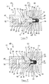
- FIGS. 3 and 4 is shown as a second embodiment, a needle valve 12, in which the valve seat sealing element 42 and the sealing member 50 as a single component in the form of a sealing body 84, are executed.
- sealing body 84 can be kept low with a suitable choice of material manufacturing and assembly costs.
- polytetrafluoroethylene (PTFE) has proven itself as a material here as well.
- a corresponding sealing body 84 of PTFE has sufficient rigidity to ensure the desired sealing effect of the needle valve 12 and sufficient flexibility to form the diaphragm collar 54 according to the specifications.
Landscapes
- Engineering & Computer Science (AREA)
- General Engineering & Computer Science (AREA)
- Mechanical Engineering (AREA)
- Lift Valve (AREA)
Abstract
Es ist ein Ventil zur Verwendung in Verbindung mit einem Beschichtungssystem (60) angegeben, insbesondere in Verbindung mit einem Beschichtungssystem (60), bei dem Lacke und/oder Härter zu einer Applikationseinrichtung gefördert werden. Ein Ventilgehäuse (14) hat eine Durchgangsöffnung (24) durch welche eine Ventilspindel (28) tritt, die zwischen einer Schließstellung und einer Freigabestellung verschiebbar gelagert ist und außerhalb des Ventilgehäuses (14) ein Ventilsitzdichtelement (42) trägt. Das Ventilsitzdichtelement (42) trägt einen Membrankragen (54), der an dem Ventilgehäuse (14) angebunden ist und die Durchgangsöffnung (24) abdichtet.

Description
Die Erfindung betrifft ein Ventil zur Verwendung in Verbindung mit einem Beschichtungssystem, insbesondere in Verbindung mit einem Beschichtungssystem, bei dem Lacke und/oder Härter zu einer Applikationseinrichtung gefördert werden, mit:
- a) einem Ventilgehäuse mit einer Durchgangsöffnung, und
- b) einer Ventilspindel, welche durch die Durchgangsöffnung hindurch tritt, zwischen einer Schließstellung und einer Freigabestellung verschiebbar gelagert ist und außerhalb des Ventilgehäuses ein Ventilsitzdichtelement trägt.
- a) a valve housing having a through opening, and
- b) a valve spindle which passes through the passage opening, is displaceably mounted between a closed position and a release position and outside of the valve housing carries a valve seat sealing element.
Bei Beschichtungssystemen wird der Materialfluss durch derartige Ventile gesteuert. Als Materialien kommen neben Lacken oder Härtern auch andere Materialien in Frage, insbesondere werden auch Reinigungs- oder Lösungsmittel durch die Leitungen gefördert, um das System zu reinigen.In coating systems, the flow of material is controlled by such valves. As materials in addition to paints or hardeners other materials in question, in particular, cleaning or solvent are conveyed through the lines to clean the system.
Ventile der eingangs genannten Art sind als Nadelventile beispielsweise aus der
Bei dem in der
In derartigen Ventilanordnungen sind Dichtungen erforderlich, die den Kolbenraum gegen einen Zuführraum auf der anderen Seite der Dichtung abdichten, welcher bei geöffnetem Ventil von dem zu fördernden Medium durchströmt wird. Zu diesem Zweck sind üblicherweise Dichtungselemente vorgesehen, die mit einer ringförmigen Dichtkante an der Ventilspindel anliegen und bei der Hubbewegung der Ventilspindel das an ihr haftende Lackmaterial oder sonstige Medien abstreifen. Bei diesen bekannten Dichtungen besteht das Problem, dass z.B. in einem Lackmaterial enthaltene Festkörper oder Lackablagerungen an der Ventilspindel usw. zu Beschädigungen der Dichtkante führen können. Auch können bestimmte in dieser Hinsicht kritische Lackmedien wie beispielsweise die Härterkomponente von 2K-Lacken, insbesondere Isocyanat, durch die Hubbewegung der Ventilspindel unter die Dichtkante gezogen werden und dann durch eine chemische Reaktion mit Feuchtigkeit aushärten, was ebenfalls zu Funktionsstörungen des Ventils führt. Neben unerwünschten Druckverlusten und dem möglichen Eindringen des Mediums in den Spindelantrieb ist eine typische Funktionsstörung des Ventils ein Anhaften der Ventilspindel in der Dichtung, was derer Bewegung verhindert.In such valve assemblies seals are required, which seal the piston chamber against a feed space on the other side of the seal, which is flowed through when the valve is open by the medium to be conveyed. For this purpose, usually sealing elements are provided, which rest with an annular sealing edge on the valve stem and strip the lifting of the valve spindle adhering to her lacquer material or other media. In these known seals there is the problem that e.g. contained in a paint material solid or paint deposits on the valve stem, etc. can cause damage to the sealing edge. Also, certain in this respect critical coating media such as the hardener component of 2K paints, in particular isocyanate, are pulled by the lifting movement of the valve stem under the sealing edge and then cured by a chemical reaction with moisture, which also leads to malfunction of the valve. In addition to unwanted pressure losses and the possible penetration of the medium in the spindle drive is a typical malfunction of the valve sticking of the valve stem in the seal, which prevents its movement.
Ein Nadelventil der eingangs genannten Art, insbesondere ein Nadelventil, bei dem bereits eine verbesserte Dichtwirkung ermöglicht ist, ist aus der
Es ist Aufgabe der Erfindung, ein Ventil der eingangs genannten Art bereitzustellen, welches diesen Gedanken Rechnung trägt.It is an object of the invention to provide a valve of the type mentioned, which takes into account this idea.
Diese Aufgabe wird dadurch gelöst, dass
- c) das Ventilsitzdichtelement einen Membrankragen trägt, der an dem Ventilgehäuse angebunden ist und die Durchgangsöffnung abdichtet.
- c) the valve seat sealing element carries a membrane collar which is connected to the valve housing and seals the passage opening.
Dadurch, dass der Membrankragen von dem Ventilsitzdichtelement getragen ist, tritt die Ventilspindel zu keinem Zeitpunkt in Kontakt mit dem zu fördernden Medium. Zwischen dem Membrankragen und dem Ventilgehäuse ist eine Art Totraum ausgebildet, in dem die Ventilspindel verläuft.Characterized in that the membrane collar is supported by the valve seat sealing element, the valve spindle never comes into contact with the medium to be conveyed. Between the diaphragm collar and the valve housing a kind of dead space is formed, in which the valve spindle extends.
Es ist insbesondere von Vorteil, wenn der Membrankragen Teil eines Dichtorganes mit einem Tragabschnitt ist, wobei der Tragabschnitt das Ventilsitzdichtelement zumindest bereichsweise abdeckt und den Membrankragen trägt. Ein derartiges Dichtorgan kann als eigenständiges Bauteil gefertigt werden, und z.B. kappenartig auf das Ventilsitzdichtelement aufgesetzt werden, was eine vereinfachte Montage und gegebenenfalls einen Austausch eines beeinträchtigten Dichtorgans erlaubt.It is particularly advantageous if the membrane collar is part of a sealing member with a support portion, wherein the support portion at least partially covers the valve seat sealing member and carries the membrane collar. Such a thing Sealing member can be manufactured as an independent component, and, for example, cap-like placed on the valve seat sealing element, which allows a simplified assembly and, where appropriate, an exchange of an impaired sealing member.
Es ist günstig, wenn der Membrankragen integral mit dem Ventilsitzdichtelement verbunden ist. Hierbei steht eine integrale Verbindung für eine unlösbare Verbindung, die beispielsweise durch Stoffschluss hergestellt wurde und die erst aus einem Rohling den Membrankragen entstehen lässt.It is advantageous if the membrane collar is integrally connected to the valve seat sealing element. Here, an integral connection stands for an inseparable connection, which was produced, for example, by material connection and which only allows the blank to form the membrane collar.
Es kann vorteilhaft sein, wenn der Tragabschnitt integral mit dem Ventilsitzdichtelement verbunden ist. Dadurch wird ein Abheben und Lösen des Tragabschnittes von dem Dichtelement verhindert.It may be advantageous if the support section is integrally connected to the valve seat sealing element. As a result, lifting and releasing of the support portion is prevented by the sealing element.
Weiterhin können das Ventilsitzdichtelement und der Membrankragen aus demselben Werkstoff gefertigt sein. Hierbei kann unter Umständen dennoch ein Tragabschnitt aus einem davon verschiedenen Werkstoff zielführend sein. Beispielsweise kann dies der Fall sein, wenn für das Tragelement, das mit einem Ventilsitz einer gesonderten Baueinheit in Kontakt steht, eine erhöhte Tragfähigkeit erwünscht ist.Furthermore, the valve seat sealing element and the membrane collar can be made of the same material. In some circumstances, a support section made of a different material may nevertheless be effective. For example, this may be the case when an increased load bearing capacity is desired for the support element in contact with a valve seat of a separate unit.
Bei einer bevorzugten Ausbildung der Erfindung ist vorgesehen, dass das Ventilsitzdichtelement und das Dichtorgan aus demselben Werkstoff gefertigt sind.In a preferred embodiment of the invention it is provided that the valve seat sealing element and the sealing member are made of the same material.
Ferner ist es von Vorteil, wenn der Membrankragen aus einem flexiblen elastischen Werkstoff gefertigt ist. Alternativ kann ein flexibler anelastischer Werkstoff verwendet werden.Furthermore, it is advantageous if the membrane collar is made of a flexible elastic material. Alternatively, a flexible anelastic material may be used.
Insbesondere ist vorgesehen, dass der Membrankragen aus einem Kunststoff besteht.In particular, it is provided that the membrane collar is made of a plastic.
Konkret haben sich in der Praxis Ventile etabliert, bei denen der Kunststoff Polytetrafluorethylen (PTFE) ist.Specifically, valves have been established in practice in which the plastic is polytetrafluoroethylene (PTFE).
Nachstehend wird ein Ausführungsbeispiel der Erfindung anhand der Zeichnungen näher erläutert. In diesen zeigen:
- Figur 1
- einen Längsschnitt eines ersten Ausführungsbeispiels eines Ventils in einer Freigabekonfiguration;
- Figur 2
- einen Längsschnitt des Ventils von
Figur 1 in einer Schließkonfiguration; - Figur 3
- einen Längsschnitt einer zweiten Ausführung eines Ventils in einer Freigabekonfiguration;
- Figur 4
- einen Längsschnitt des Ventils von
Figur 3 in einer Schließkonfiguration.
- FIG. 1
- a longitudinal section of a first embodiment of a valve in a release configuration;
- FIG. 2
- a longitudinal section of the valve of
FIG. 1 in a closed configuration; - FIG. 3
- a longitudinal section of a second embodiment of a valve in a release configuration;
- FIG. 4
- a longitudinal section of the valve of
FIG. 3 in a closed configuration.
In den
Das Ventilgehäuse 14 begrenzt einen Kolbenraum 20. Ein Steuerkanal 22 durchdringt den Gehäusekörper 16 in radialer Richtung und mündet in den Kolbenraum 20, so dass die Zufuhr des Druckfluids in den Kolbenraum 20 ermöglicht ist.The
An der von dem Gehäusedeckel 18 abliegenden Stirnseite weist der Gehäusekörper 16 eine dazu koaxiale Durchgangsöffnung 24 auf, die in den Kolbenraum 20 mündet und koaxial zu diesem verläuft. Die Durchgangsöffnung 24 wird dabei durch eine kreiszylindrische Führungsfläche 26 begrenzt, die eine verschiebbar gelagerte Ventilspindel 28 führt.On the side facing away from the
Innerhalb des Ventilgehäuses 14 weist die Ventilspindel 28 einen Federaufnahmeabschnitt 30 auf, der in eine zylindrische Druckfeder 32 hineinragt, welche sich im Kolbenraum 20 an dem Gehäusedeckel 18 abstützt. Durch die Druckfeder 32 wird die Ventilspindel 28 unter Federvorspannung in eine Schließstellung gedrückt, in der die Ventilspindel 32 weiter aus dem Ventilgehäuse 12 ausgefahren ist als in einer Freigabestellung. Der Federaufnahmeabschnitt 30 ist derart dimensioniert, dass ein zur Erreichung der Freigabestellung notwendiger Federweg gewährleistet ist.Within the
An den Federaufnahmeabschnitt 30 schließt sich ein umlaufend radial überstehendes Kolbenelement 34 an, das bewegungsfest von der Ventilspindel 28 umfasst ist und an dem die Druckfeder 32 mit ihrem von dem Gehäusedeckel abliegenden Ende angreift. Das Kolbenelement 34 befindet sich im Kolbenraum 20 und hat in axialer Richtung eine Erstreckung, die kürzer ist als die Länge des Kolbenraums 20 in dieser Richtung.To the
Dem Kolbenelement 34 folgt ein Führungsabschnitt 36 der Ventilspindel 28, der an der dazu komplementären Führungsfläche 26 der Durchgangsöffnung 24 im Gehäusekörper 14 läuft.The
Das Kolbenelement 34 trägt in Umfangsrichtung einen nicht eigens gezeigten Dichtring, der das Kolbenelement 34 gegen die Innenwand des Kolbenraums 20 abdichtet. Außerdem ist an der Durchgangsöffnung 24 des Ventilgehäuses 14 eine Ringdichtung 38 vorhanden, die den Kolbenraum 20 nach außen abdichtet und dort das Austreten des Druckfluids verhindert. Außerhalb des Ventilgehäuses 14 trägt schließlich die Ventilspindel 28 an einem Spindelkopfende 40 ein Ventilsitzdichtelement 42. Dieses ist beispielsweise über einen Rastabschnitt durch Aufstecken auf der Ventilspindel 28 verrastet, wie es an und für sich bekannt ist. Alternativ kann das Ventilsitzdichtelement 42 beispielsweise im Falle eines metallischen Ventilsitzdichtelements mittels einer Presspassung, oder im Falle eines Ventilsitzdichtelements aus einer Keramik oder aus einem Kunststoff mittels einer Klebeverbindung an dem Spindelkopfende 40 befestigt sein.The
Das Ventilsitzdichtelement 42 umfasst einen Verbindungsabschnitt 44, der mit der Ventilspindel 28 in Kontakt steht, einen Körperabschnitt 46, der im Wesentlichen kreiszylindrisch ausgestaltet ist, und einen kegelstumpfförmigen Sitzabschnitt 48, der an dem freien Kopfende des Ventilsitzdichtelements 42 gebildet ist.The valve
Bei dem in den
Bei einer weiteren nicht eigens gezeigten Abwandlung kann auf den Tragabschnitt 52 verzichtet werden. In diesem Fall ist der Membrankragen 54 unmittelbar an das Ventilsitzdichtelements 42 angebunden. Für die Abdichtung der Durchgangsöffnung 24 ist grundsätzlich allein der Membrankragen 54 nötig, welcher dann z.B. am Verbindungsabschnitt 44 des Ventilsitzdichtelements 42 getragen und mit diesem integral verbunden ist.In another not specifically shown modification can be dispensed with the
Das beschriebene Nadelventil 14 kann beispielsweise in einer Ventilaufnahme 56 einer Wechseleinheit 58 eingebaut sein, die Teil eines Beschichtungssystems 60 ist, von der in den Figuren lediglich ein Ausschnitt gezeigt ist. Über einen Zuführkanal 62 wird das zu fördernde Medium, beispielsweise Lack oder Härter, einem Zuführraum 64 der Wechseleinheit 58 zugeführt. Ein Abgabekanal 66 ist über einen Ventilsitz 68 mit dem Zuführraum 64 verbunden und leitet das zu fördernde Medium beispielsweise einer Applikationseinrichtung zu.The described
In ihrer Schließstellung ist die Ventilspindel 28 durch die Federkraft der Druckfeder 32 so weit aus dem Ventilgehäuse 14 ausgefahren, dass das Ventilsitzdichtelement 42 in den Ventilsitz 68 der Wechseleinheit 58 gepresst wird, so dass dieser dicht verschlossen ist. Kontaktflächen des Ventilsitzdichtelements 42 und des Ventilsitzes 68 sind komplementär zueinander, um eine optimale Dichtwirkung zu erzielen. Beim vorliegenden Ausführungsbeispiel sind solche Kontaktflächen konisch ausgebildet.In its closed position, the
Der Kontakt zwischen Nadelventil 12 und Ventilsitz 68 erfolgt über den Tragabschnitt 52 des Dichtorgans 50, welcher das Ventilsitzdichtelement 42 abdeckt und dazu eine Kontaktflächenform aufweist, die zu dem Ventilsitz 68 komplementär ausgebildet ist. Die Kontaktflächenform des Sitzabschnitts 48 des Ventilsitzdichtelements 42 unterstützt hierbei die Kraftübertragung auf den Tragabschnitt 52 und verhilft damit zu einer sicheren Dichtung bei der Schließkonfiguration des Nadelventils 12.The contact between
In dem oben angesprochenen Fall, dass kein Tragabschnitt 52 vorhanden ist, kann der Kontakt nur über den Sitzbereich 48 des Ventilsitzdichtelements 42 erfolgen.In the above-mentioned case that no
An den Tragabschnitt 52 schließt umlaufend der Membrankragen 54 an, der sich in der Schließstellung wie in
Der Halteabschnitt 74 ist komplementär zu einer Halteschulter 78 des Ventilgehäuses 14 ausgebildet, über welche der Halteabschnitt 74 an das Ventilgehäuse 14 angebunden ist. Die Anbindung kann vom Zweck her unlösbar, beispielsweise mittels Kleben, ausgeführt sein. Alternativ kann die Anbindung auch lösbar, beispielsweise durch Aufstecken, erfolgen.The holding
Der Membranabschnitt 76, als Verbindungsstück zwischen dem Dichtelementabschnitt 72 und dem Gehäuseabschnitt 74, erfüllt die eigentliche Funktion des Abdichtens der Durchgangsöffnung 24 gegen die Außenumgebung des Ventils 10.The
Wird nun über den Steuerkanal 22 dem Kolbenraum 20 Druckluft zugeführt und die Federkraft der Druckfeder 32 überwunden, so bewegt sich die Ventilspindel 28 von dem Ventilsitz 68 weg und das Nadelventil 12 geht in die in
Dabei kann sich der Membranabschnitt 76 falten und eine entsprechende Welle 80 kann zum Teil in eine Aufnahmefase 82 des Ventilgehäuses 14 eintreten. Hierzu ist vorzugsweise das komplette Dichtorgan 50, insbesondere jedoch zumindest der Membrankragen 76 aus einem flexiblen Kunststoff gefertigt, welcher elastisch oder anelastisch sein kann. Der Membranabschnitt 76 ist dermaßen ausgelegt, dass dieser in der Schließstellung nicht auf Zug belastet wird, so dass eine höhere Bauteilwechselfestigkeit gewährleistet wird. Als Material für den Membrankragen 54 und/oder den Tragabschnitt 52 ist ein flexibler Kunststoff vorgesehen, wobei Polytetrafluorethylen (PTFE) besonders von Vorteil ist. Aber auch andere fluorhaltige Kunststoffe sind hier geeignet. Zum Beispiel kommen Perfluorethylenpropylen FEP, Perfluoralkoxylalkane PFA, Polyvinylidenfluorid PVDF oder auch fluorhaltige Elastomere und auch allgemein vernetzte Elastomere in Frage.In this case, the
In den
Bei einem solchen Dichtkörper 84 lassen sich bei geeigneter Wahl des Werkstoffs Herstell- und Montagekosten niedrig halten. In der Praxis hat sich auch hier als Material Polytetrafluorethylen (PTFE) bewährt. Ein entsprechender Dichtkörper 84 aus PTFE hat genügend Steifigkeit, um die gewünschte Dichtwirkung des Nadelventils 12 zu gewährleisten und ausreichend Flexibilität, um den Membrankragen 54 entsprechend der Vorgaben auszubilden.In such a
Claims (9)
Applications Claiming Priority (1)
| Application Number | Priority Date | Filing Date | Title |
|---|---|---|---|
| DE102014012705.2A DE102014012705A1 (en) | 2014-08-27 | 2014-08-27 | Valve |
Publications (1)
| Publication Number | Publication Date |
|---|---|
| EP2990124A1 true EP2990124A1 (en) | 2016-03-02 |
Family
ID=53836353
Family Applications (1)
| Application Number | Title | Priority Date | Filing Date |
|---|---|---|---|
| EP15002401.6A Withdrawn EP2990124A1 (en) | 2014-08-27 | 2015-08-13 | Valve |
Country Status (2)
| Country | Link |
|---|---|
| EP (1) | EP2990124A1 (en) |
| DE (1) | DE102014012705A1 (en) |
Cited By (1)
| Publication number | Priority date | Publication date | Assignee | Title |
|---|---|---|---|---|
| US10807110B2 (en) | 2015-07-03 | 2020-10-20 | Dürr Systems Ag | Applicator, in particular rotary atomiser |
Families Citing this family (13)
| Publication number | Priority date | Publication date | Assignee | Title |
|---|---|---|---|---|
| DE102015008661A1 (en) | 2015-07-03 | 2017-01-05 | Dürr Systems Ag | needle valve |
| DE102015008659B4 (en) | 2015-07-03 | 2019-06-19 | Dürr Systems Ag | Coating agent valve and rotary atomizer |
| DE102016014944A1 (en) | 2016-12-14 | 2018-06-14 | Dürr Systems Ag | Coating method and corresponding coating device |
| DE102016014948A1 (en) | 2016-12-14 | 2018-06-14 | Dürr Systems Ag | Printhead and related operating procedures |
| DE102016014947A1 (en) | 2016-12-14 | 2018-06-14 | Dürr Systems Ag | Printhead for applying a coating agent |
| DE102016014951A1 (en) | 2016-12-14 | 2018-06-14 | Dürr Systems Ag | Coating device and associated operating method |
| DE102016014952A1 (en) | 2016-12-14 | 2018-06-14 | Dürr Systems Ag | Coating device for coating components |
| DE102016014919A1 (en) | 2016-12-14 | 2018-06-14 | Dürr Systems Ag | Application device and method for applying a coating agent |
| DE102016014955A1 (en) | 2016-12-14 | 2018-06-14 | Dürr Systems Ag | Coating device and corresponding coating method |
| DE102016014956A1 (en) | 2016-12-14 | 2018-06-14 | Dürr Systems Ag | Coating device and associated operating method |
| DE102016014943A1 (en) | 2016-12-14 | 2018-06-14 | Dürr Systems Ag | Printhead with tempering device |
| DE102016014953A1 (en) | 2016-12-14 | 2018-06-14 | Dürr Systems Ag | Painting plant and corresponding painting process |
| DE102016014946A1 (en) | 2016-12-14 | 2018-06-14 | Dürr Systems Ag | Printhead for applying a coating agent to a component |
Citations (7)
| Publication number | Priority date | Publication date | Assignee | Title |
|---|---|---|---|---|
| JPH061961U (en) * | 1992-06-18 | 1994-01-14 | 旭有機材工業株式会社 | Control valve |
| WO1999053231A1 (en) * | 1998-04-11 | 1999-10-21 | Tuchenhagen Gmbh | Bellows for sealing a valve rod passage in a globe valve |
| WO2002048587A1 (en) * | 2000-12-13 | 2002-06-20 | Abb K. K. | Stop valve for paint |
| WO2004013524A1 (en) * | 2002-08-06 | 2004-02-12 | Fedegari Autoclavi Spa | Sanitary diaphragm valve |
| DE102005033191A1 (en) * | 2004-07-16 | 2006-02-16 | Smc K.K. | Color selector valve |
| DE102006025549A1 (en) | 2006-06-01 | 2007-12-06 | Eisenmann Lacktechnik Gmbh & Co. Kg | Valve used in connection with application device standing on electrical potential, has valve housing, valve spindle with free end and another free end mounted displaceable between closing position and opening position |
| DE102007037663A1 (en) | 2007-08-09 | 2009-02-19 | Dürr Systems GmbH | Needle valve assembly |
Family Cites Families (3)
| Publication number | Priority date | Publication date | Assignee | Title |
|---|---|---|---|---|
| DE902924C (en) * | 1952-03-29 | 1954-01-28 | Schneider Bochumer Maschf A | Cuff valve |
| DE1084996B (en) * | 1954-07-27 | 1960-07-07 | Rheinisches Metallwerk Gmbh | Gate valve with a closing piece that is provided with a rubber cover |
| JP4310532B2 (en) * | 2002-11-27 | 2009-08-12 | Smc株式会社 | Flow control valve |
-
2014
- 2014-08-27 DE DE102014012705.2A patent/DE102014012705A1/en not_active Ceased
-
2015
- 2015-08-13 EP EP15002401.6A patent/EP2990124A1/en not_active Withdrawn
Patent Citations (7)
| Publication number | Priority date | Publication date | Assignee | Title |
|---|---|---|---|---|
| JPH061961U (en) * | 1992-06-18 | 1994-01-14 | 旭有機材工業株式会社 | Control valve |
| WO1999053231A1 (en) * | 1998-04-11 | 1999-10-21 | Tuchenhagen Gmbh | Bellows for sealing a valve rod passage in a globe valve |
| WO2002048587A1 (en) * | 2000-12-13 | 2002-06-20 | Abb K. K. | Stop valve for paint |
| WO2004013524A1 (en) * | 2002-08-06 | 2004-02-12 | Fedegari Autoclavi Spa | Sanitary diaphragm valve |
| DE102005033191A1 (en) * | 2004-07-16 | 2006-02-16 | Smc K.K. | Color selector valve |
| DE102006025549A1 (en) | 2006-06-01 | 2007-12-06 | Eisenmann Lacktechnik Gmbh & Co. Kg | Valve used in connection with application device standing on electrical potential, has valve housing, valve spindle with free end and another free end mounted displaceable between closing position and opening position |
| DE102007037663A1 (en) | 2007-08-09 | 2009-02-19 | Dürr Systems GmbH | Needle valve assembly |
Cited By (3)
| Publication number | Priority date | Publication date | Assignee | Title |
|---|---|---|---|---|
| US10807110B2 (en) | 2015-07-03 | 2020-10-20 | Dürr Systems Ag | Applicator, in particular rotary atomiser |
| EP3317023B1 (en) * | 2015-07-03 | 2020-12-30 | Dürr Systems AG | Applicator, in particular rotary atomizer |
| US11623232B2 (en) | 2015-07-03 | 2023-04-11 | Dürr Systems Ag | Applicator, in particular rotary atomiser |
Also Published As
| Publication number | Publication date |
|---|---|
| DE102014012705A1 (en) | 2016-03-17 |
Similar Documents
| Publication | Publication Date | Title |
|---|---|---|
| EP2990124A1 (en) | Valve | |
| DE102007037663A1 (en) | Needle valve assembly | |
| WO2015149919A1 (en) | Valve | |
| EP2397727B1 (en) | Multi-part valve disc | |
| DE102008044819A1 (en) | Hydraulic element | |
| EP3317003B1 (en) | Coating agent valve | |
| EP3317570B1 (en) | Needle valve | |
| EP2213850B1 (en) | Seal assembly for a turning head | |
| EP2855943A1 (en) | Master cylinder | |
| EP2833042B1 (en) | Valve assembly for switching and/or regulating a media flow of an aerospace engine and aerospace engine | |
| DE102014004668A1 (en) | Valve | |
| EP1703185B1 (en) | Coaxial valve | |
| EP2924327B1 (en) | Multi-port valve | |
| DE102014013992A1 (en) | Piston of a fluid-operated linear drive and associated linear drive | |
| DE102014117458B4 (en) | Valve arrangement for a rotary-fixed transition, wheel unit with a rotary-fixed transition, and pressure medium supply device for a wheel unit | |
| DE102006022212A1 (en) | Spring arrangement for use as component of compression unit for sealing agent, has locking cover, which is connected with housing by separate locking element | |
| WO2017174064A1 (en) | Seal for a piston/cylinder arrangement | |
| EP3714992B1 (en) | Device for dispensing a flowable medium and method for operating such a device | |
| DE102009021902A1 (en) | Concentric slave cylinder arrangement for use in clutch actuation device, has inner and outer circular stripping elements with stripping regions lying at inner circumference and outer circumference of cylinder body regions, respectively | |
| AT394764B (en) | HYDRAULIC PRESSURE TRANSLATOR | |
| WO2020187673A1 (en) | Valve device | |
| DE102014216619A1 (en) | Slave cylinder for actuating a clutch, coupling for a motor vehicle and motor vehicle with a corresponding coupling | |
| WO2011150913A1 (en) | Hydraulic cylinder | |
| EP2990281B1 (en) | Coupling head | |
| DE102016103958A1 (en) | Pilot controlled safety valve |
Legal Events
| Date | Code | Title | Description |
|---|---|---|---|
| PUAI | Public reference made under article 153(3) epc to a published international application that has entered the european phase |
Free format text: ORIGINAL CODE: 0009012 |
|
| AK | Designated contracting states |
Kind code of ref document: A1 Designated state(s): AL AT BE BG CH CY CZ DE DK EE ES FI FR GB GR HR HU IE IS IT LI LT LU LV MC MK MT NL NO PL PT RO RS SE SI SK SM TR |
|
| AX | Request for extension of the european patent |
Extension state: BA ME |
|
| STAA | Information on the status of an ep patent application or granted ep patent |
Free format text: STATUS: THE APPLICATION IS DEEMED TO BE WITHDRAWN |
|
| 18D | Application deemed to be withdrawn |
Effective date: 20160903 |