EP3316445A2 - System mit magneten zum drahtlosen laden - Google Patents
System mit magneten zum drahtlosen laden Download PDFInfo
- Publication number
- EP3316445A2 EP3316445A2 EP17198421.4A EP17198421A EP3316445A2 EP 3316445 A2 EP3316445 A2 EP 3316445A2 EP 17198421 A EP17198421 A EP 17198421A EP 3316445 A2 EP3316445 A2 EP 3316445A2
- Authority
- EP
- European Patent Office
- Prior art keywords
- wireless power
- solenoid
- power receiving
- power transmitting
- receiving device
- Prior art date
- Legal status (The legal status is an assumption and is not a legal conclusion. Google has not performed a legal analysis and makes no representation as to the accuracy of the status listed.)
- Withdrawn
Links
Images








Classifications
-
- H—ELECTRICITY
- H02—GENERATION; CONVERSION OR DISTRIBUTION OF ELECTRIC POWER
- H02J—ELECTRIC POWER NETWORKS; CIRCUIT ARRANGEMENTS OR SYSTEMS FOR SUPPLYING OR DISTRIBUTING ELECTRIC POWER; SYSTEMS FOR STORING ELECTRIC ENERGY
- H02J50/00—Circuit arrangements or systems for wireless supply or distribution of electric power
- H02J50/10—Circuit arrangements or systems for wireless supply or distribution of electric power using inductive coupling
-
- A—HUMAN NECESSITIES
- A44—HABERDASHERY; JEWELLERY
- A44C—PERSONAL ADORNMENTS, e.g. JEWELLERY; COINS
- A44C5/00—Bracelets; Wrist-watch straps; Fastenings for bracelets or wrist-watch straps
- A44C5/14—Bracelets; Wrist-watch straps; Fastenings for bracelets or wrist-watch straps characterised by the way of fastening to a wrist-watch or the like
-
- G—PHYSICS
- G06—COMPUTING OR CALCULATING; COUNTING
- G06F—ELECTRIC DIGITAL DATA PROCESSING
- G06F1/00—Details not covered by groups G06F3/00 - G06F13/00 and G06F21/00
- G06F1/16—Constructional details or arrangements
-
- H—ELECTRICITY
- H01—ELECTRIC ELEMENTS
- H01F—MAGNETS; INDUCTANCES; TRANSFORMERS; SELECTION OF MATERIALS FOR THEIR MAGNETIC PROPERTIES
- H01F27/00—Details of transformers or inductances, in general
- H01F27/02—Casings
-
- H—ELECTRICITY
- H01—ELECTRIC ELEMENTS
- H01F—MAGNETS; INDUCTANCES; TRANSFORMERS; SELECTION OF MATERIALS FOR THEIR MAGNETIC PROPERTIES
- H01F27/00—Details of transformers or inductances, in general
- H01F27/24—Magnetic cores
-
- H—ELECTRICITY
- H01—ELECTRIC ELEMENTS
- H01F—MAGNETS; INDUCTANCES; TRANSFORMERS; SELECTION OF MATERIALS FOR THEIR MAGNETIC PROPERTIES
- H01F27/00—Details of transformers or inductances, in general
- H01F27/24—Magnetic cores
- H01F27/25—Magnetic cores made from strips or ribbons
-
- H—ELECTRICITY
- H01—ELECTRIC ELEMENTS
- H01F—MAGNETS; INDUCTANCES; TRANSFORMERS; SELECTION OF MATERIALS FOR THEIR MAGNETIC PROPERTIES
- H01F27/00—Details of transformers or inductances, in general
- H01F27/28—Coils; Windings; Conductive connections
- H01F27/2823—Wires
-
- H—ELECTRICITY
- H01—ELECTRIC ELEMENTS
- H01F—MAGNETS; INDUCTANCES; TRANSFORMERS; SELECTION OF MATERIALS FOR THEIR MAGNETIC PROPERTIES
- H01F38/00—Adaptations of transformers or inductances for specific applications or functions
- H01F38/14—Inductive couplings
-
- H—ELECTRICITY
- H01—ELECTRIC ELEMENTS
- H01F—MAGNETS; INDUCTANCES; TRANSFORMERS; SELECTION OF MATERIALS FOR THEIR MAGNETIC PROPERTIES
- H01F7/00—Magnets
- H01F7/06—Electromagnets; Actuators including electromagnets
-
- H—ELECTRICITY
- H02—GENERATION; CONVERSION OR DISTRIBUTION OF ELECTRIC POWER
- H02J—ELECTRIC POWER NETWORKS; CIRCUIT ARRANGEMENTS OR SYSTEMS FOR SUPPLYING OR DISTRIBUTING ELECTRIC POWER; SYSTEMS FOR STORING ELECTRIC ENERGY
- H02J50/00—Circuit arrangements or systems for wireless supply or distribution of electric power
- H02J50/005—Mechanical details of housing or structure aiming to accommodate the power transfer means, e.g. mechanical integration of coils, antennas or transducers into emitting or receiving devices
-
- H—ELECTRICITY
- H02—GENERATION; CONVERSION OR DISTRIBUTION OF ELECTRIC POWER
- H02J—ELECTRIC POWER NETWORKS; CIRCUIT ARRANGEMENTS OR SYSTEMS FOR SUPPLYING OR DISTRIBUTING ELECTRIC POWER; SYSTEMS FOR STORING ELECTRIC ENERGY
- H02J50/00—Circuit arrangements or systems for wireless supply or distribution of electric power
- H02J50/40—Circuit arrangements or systems for wireless supply or distribution of electric power using two or more transmitting or receiving devices
-
- H—ELECTRICITY
- H02—GENERATION; CONVERSION OR DISTRIBUTION OF ELECTRIC POWER
- H02J—ELECTRIC POWER NETWORKS; CIRCUIT ARRANGEMENTS OR SYSTEMS FOR SUPPLYING OR DISTRIBUTING ELECTRIC POWER; SYSTEMS FOR STORING ELECTRIC ENERGY
- H02J50/00—Circuit arrangements or systems for wireless supply or distribution of electric power
- H02J50/90—Circuit arrangements or systems for wireless supply or distribution of electric power involving detection or optimisation of position, e.g. alignment
-
- H—ELECTRICITY
- H02—GENERATION; CONVERSION OR DISTRIBUTION OF ELECTRIC POWER
- H02J—ELECTRIC POWER NETWORKS; CIRCUIT ARRANGEMENTS OR SYSTEMS FOR SUPPLYING OR DISTRIBUTING ELECTRIC POWER; SYSTEMS FOR STORING ELECTRIC ENERGY
- H02J7/00—Circuit arrangements for charging or discharging batteries or for supplying loads from batteries
- H02J7/70—Circuit arrangements for charging or discharging batteries or for supplying loads from batteries characterised by the mechanical construction
-
- H—ELECTRICITY
- H02—GENERATION; CONVERSION OR DISTRIBUTION OF ELECTRIC POWER
- H02J—ELECTRIC POWER NETWORKS; CIRCUIT ARRANGEMENTS OR SYSTEMS FOR SUPPLYING OR DISTRIBUTING ELECTRIC POWER; SYSTEMS FOR STORING ELECTRIC ENERGY
- H02J7/00—Circuit arrangements for charging or discharging batteries or for supplying loads from batteries
- H02J7/70—Circuit arrangements for charging or discharging batteries or for supplying loads from batteries characterised by the mechanical construction
- H02J7/731—Circuit arrangements for charging or discharging batteries or for supplying loads from batteries characterised by the mechanical construction specially adapted for holding portable devices containing batteries
Definitions
- This relates generally to wireless systems, and, more particularly, to systems in which devices are wirelessly charged.
- a wireless power transmitting device such as a device with a charging surface or magnetic charging cable may wirelessly transmit power to a portable electronic device.
- the portable electronic device may receive the wirelessly transmitted power and may use this power to charge an internal battery or to power the device.
- it may be challenging to achieve desired levels of charging efficiency due to the way in which the portable electronic device and wireless power transmitting device are oriented with respect to each other and the configurations used for the wireless charging components in these devices.
- a wireless power transmitting device such as a device with a wireless charging surface or a device with a cradle or other support structure can transmit power wirelessly to a wireless power receiving device.
- the wireless power receiving device may have a housing such as a metal housing.
- a display may be mounted in the metal housing on a front face of the device.
- a rear housing wall on a rear face of the device may be provided with a wireless power receiving solenoid.
- the wireless power receiving solenoid may have a core formed from a magnetic material such as a ferrite strip that is wrapped with a wire.
- the wire may be formed from a solid metal wire with a dielectric coating, a solid metal wire with a magnetic coating layer, a metal wire having a rectangular cross-sectional shape, or a wire formed form intertwined metal filaments.
- the solenoid may have a linear strip shape that extends along a longitudinal axis.
- the wireless power receiving device may have a strap coupled to sidewalls of the metal housing.
- the longitudinal axis may extend in a direction that is perpendicular to the strap and parallel to the sidewalls to which the strap is coupled.
- the wireless power receiving solenoid may have opposing first and second ends.
- the wireless power transmitting device may have a wireless power transmitting solenoid with opposing first and second ends that are configured to transmit wireless power signals respectively to the first and second ends of the wireless power receiving solenoid when the wireless power receiving solenoid has been received within a cradle.
- the wireless power receiving device may also use the wireless power receiving solenoid to receive power from a wireless charging mat or other wireless power transmitting device that emits wireless power signals from a wireless charging surface.
- the wireless power receiving device may be a cellular telephone, watch, media player, tablet computer, earbuds, remote control, laptop computer, or other portable electronic device.
- the wireless power receiving device may have a wireless power receiving solenoid that receives wireless power signals transmitted by the wireless power transmitting device.
- the wireless power transmitting device may supply alternating-current signals to one or more wireless power transmitting coils. This causes the coils to transmit alternating-current electromagnetic signals (sometimes referred to as wireless power signals) to the wireless power receiving device.
- the wireless power receiving device may have one or more coils such as an elongated wireless power receiving solenoid for receiving the transmitted wireless power signals.
- wireless power system 8 may include a wireless power transmitting device such as wireless power transmitting device 12 and may include one or more wireless power receiving devices 10.
- Power transmitting device 12 may be a stand-alone power adapter or equipment that is coupled to power adapter circuitry using a cable.
- Device 12 may be a wireless charging mat with an array of coils mounted under a planar dielectric layer that serves as a wireless charging surface, a device with a charging cable (e.g., a magnetic charging cable having a puck with a wireless power transmitting coil and magnets for coupling the puck to a wireless power receiving device), a stand (e.g., a dock), a table with an array of coils, or other device that includes power adapter circuitry, may include a wireless charging cradle or other wireless power transfer component that is coupled to a power adapter or other equipment by a cable, may be a portable device, may be equipment that has been incorporated into furniture, a vehicle, or other system, or may be other wireless power transfer equipment.
- wireless power transmitting device 12 is a wireless charging device with a wireless charging surface or a wireless charging cradle of the type that may be incorporated into a puck on a cable or a cradle in a dock or other stand may sometimes be described herein as examples.
- a controller in control circuitry 42 may use wireless power transmitting circuitry 34 and one or more coil(s) 36 coupled to circuitry 34 to transmit alternating current electromagnetic signals 48 to device 10 and thereby convey wireless power to power receiving circuitry 46 of device 10.
- Power transmitting circuitry 34 may have switching circuitry (e.g., transistors) that are turned on and off based on control signals provided by control circuitry 42 to create AC current signals through coil(s) 36.
- switching circuitry e.g., transistors
- Control circuitry 42 and 20 may include storage and may include processing circuitry such as microprocessors, power management units, baseband processors, digital signal processors, microcontrollers, and/or application-specific integrated circuits with processing circuits. Control circuitry 42 and 20 may be configured to execute instructions for implementing desired control and communications features in system 8.
- control circuitry 42 and/or 20 may be used in determining power transmission levels, processing sensor data, processing user input, processing other information such as information on wireless coupling efficiency from transmitting circuitry 34, processing information from receiving circuitry 46, using information from circuitry 34 and/or 46 to determine when to start and stop wireless charging operations, adjusting charging parameters such as charging frequencies, coil assignments in a multi-coil array, and wireless power transmission levels, and performing other control functions.
- Control circuitry 42 and/or 20 may be configured to perform these operations using hardware (e.g., dedicated hardware or circuitry) and/or software (e.g., code that runs on the hardware of system 8).
- Software code for performing these operations may be stored on non-transitory computer readable storage media (e.g., tangible computer readable storage media).
- Device 12 and/or device 10 may communicate wirelessly using in-band or out-of-band communications.
- Devices 10 and 12 may, for example, have wireless transceiver circuitry in control circuitry 42 and 20 (and/or wireless communications circuitry such as circuitry 56 of FIG. 1 ) that allows wireless transmission of signals between devices 10 and 12 (e.g., using antennas, using coils 36 and 14, etc.).
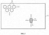
- wireless transmitting device 12 is a wireless charging mat or other wireless power transmitting equipment that has an array of coils that supply wireless power over a wireless charging surface. This type of arrangement is shown in FIG. 2 . As shown in FIG. 2 , wireless power receiving device 10 may be located over one or more of coils 36 during charging. Coils 36 may be arranged across a charging surface with any suitable tiling pattern (rectangular, hexagonal, etc.).
- a coil array may have rows and columns of coils 36 each of which is placed in a non-overlapping rectangular tile location, a coil array may have rectangularly tiled rows and columns of coils 36 in two or more staggered arrays, may have coils 36 in a hexagonally tiled array pattern such as a pattern in which each hexagonal tile includes a respective non-overlapping coil 36, or may be arranged in a set of two or more or three or more overlapping hexagonally tiled sets of coils.
- An illustrative coil array configuration based on three staggered sets (arrays) of hexagonally tiled coils 36 is shown in FIG. 3 .
- housing 62 may be formed from a metal rear housing wall structure or other suitable housing wall structure and may be provided with windows to accommodate light emission and/or light detection and/or may be provided with a solenoid (coil) 14 to receive wireless power from device 12.
- a solenoid (coil) 14 to receive wireless power from device 12.
- a solenoid on the rear face of housing 62 of device 10 may have a linear configuration of the type shown by illustrative solenoid 14 of FIG. 5 .
- Solenoid 14 of FIG. 5 has an elongated linear core such as strip-shaped solenoid core 14C wrapped with multiple turns of wire 14W.
- Core 14C may be formed from a magnetic material having a relatively high relative permeability.
- the relative permeability of core 14C may be 1000-5000 at 300-400 kHz, at least 1000 at 300-400 kHz, 2000-6000 at 300-400 kHz, or less than 6000 at 300-400 kHz. If desired, the relative permeability of core 14C may be lower or higher. As an example, if circuitry 34 and 46 is configured to operate at a higher frequency (e.g., 6 MHz), the relative permeability of core 14C may be 100 at 6 MHz.
- Core 14C may be formed from a ferrite (e.g., a magnesium zinc ferrite) or other suitable magnetic material.
- Wire 14W may be formed from solid copper wire or other suitable conductive strands of material. There may be 2-100, more than 10, more than 40, more than 120, less than 300, less than 150, less than 75, or other suitable number of turns of wire 14W wrapped around core 14C (longitudinal axis 70).
- the diameter of wire 14W may be 0.1 mm, 0.05-0.2 mm, more than 0.03 mm, more than 0.08 mm, less than 0.3 mm, less than 1 mm, or other suitable diameter.
- a user may place housing 62 on a charging surface so that the front or rear face of housing 62 lies flat on the charging surface.
- housing 62 may be placed so that the front and rear faces of housing 62 each lie in a plane parallel to the charging surface of device 12 (parallel to the X-Y plane).
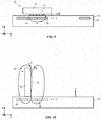
- magnetic field B from coil(s) 36 may pass laterally (horizontally in the configuration of FIG. 9 ) through solenoid 14.
- a user may place housing 62 on its side on a wireless charging surface, as shown in FIG. 10 .
- the user may place the watch on a charging surface so that the sidewalls of housing 62 that are most adjacent to wrist strap 60 (the vertically extending sidewalls of housing 62 in the example of FIG. 10 ) are oriented parallel to surface normal n of the charging surface of wireless device 12 (along the vertical Z axis).
- Strap 60 may extend parallel to the charging surface and may be perpendicular to surface normal n.
- band 60 is an elastomeric loop and has no clasps
- magnetic field B from coil(s) 36 may pass vertically through solenoid 14 (along axis Z of FIG. 10 ).
- a rear-mounted solenoid such as solenoid 14 in the examples of FIGS. 9 and 10 allows device 10 to receive satisfactory wireless power in both horizontal (parallel) and vertical (perpendicular) orientations of solenoid 14 (longitudinal axis 70) relative to the coil array formed under the charging surface of device 12.
- the coupling efficiency between devices 12 and 10 in the scenarios of FIGS. 9 and 10 may be, for example, between 5% and 25%, above 4%, below 30%, or other suitable values.
- Coils 36 may have any suitable shape and size.
- coils 36 may be hexagonally tiled coils in three staggered layers (as described in connection with FIG. 3 ) and may have coil diameters of 1-10 cm, 2-5 cm, 2-4 cm, 2-3 cm, more than 0.5 cm, less than 15 cm, or other suitable coil diameter values.
- FIG. 11 is a perspective view of device 10 in an illustrative configuration in which solenoid 14 is oriented perpendicular to the surface (X-Y plane) of device 12.
- solenoid 14 may have an elongated shape (e.g., an elongated strip shape) that extends across some or all of rear wall 62R of housing 62. Configurations in which solenoid 14 is mounted elsewhere in watch housing 62 may also be used.
- solenoid 14 may be desirable to place solenoid 14 within a charging cradle in device 12 during charging.
- a cradle in device 12 may, for example, have a single wireless power transmitting coil such as illustrative C-shaped solenoid 36 of FIG. 12 .
- solenoid 36 may, in this illustrative configuration, have multiple turns of wire 36W (e.g., wire such as wire 14W of solenoid 14) wrapped around magnetic core 36C (see, e.g., the materials and structures used in forming core 14C of solenoid 14).
- This type of arrangement for wireless power transmitting solenoid 36 may be used in a wireless charging puck, in a stand, in a puck or other device that is tethered to the end of a cable, or other wireless power transmitting device 12.
- the C shape of core 36C allows the ends of wireless power transmitting solenoid 36 (e.g., ends 72 of core 36C) to be placed adjacent to ends 74 of core 14W (e.g., the opposing ends of solenoid 14), thereby enhancing the efficiency with which magnetic field B from C-shaped solenoid 36 is coupled into solenoid 14.
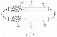
- solenoid 36 may be formed from a linear solenoid core and solenoid 14 may be formed from a linear solenoid core, as shown in FIG. 13 .
- solenoids 36 and 14 are elongated linear solenoids
- the opposing ends of power transmitting solenoid 36 may be placed adjacent to corresponding ends of power receiving solenoid 14 to enhance power transfer efficiency.
- Solenoids 36 of FIG. 13 may be mounted in a support structure such as a cradle in device 12.
- Solenoid 14 of FIG. 13 may be mounted on housing 62 at the rear face of device 10.
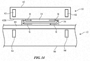
- FIG. 14 is a cross-sectional side view of system 8 in an illustrative configuration in which wireless power transmitting device 12 has a U-shaped wireless power transmitting solenoid 36.
- Wireless power receiving solenoid 14 may be a linear solenoid that is received within a cavity formed between the opposing ends of U-shaped power transmitting solenoid 36.
- power may be transmitted wirelessly when solenoid 14 is receiving within a cradle recess or other support structure cavity so that the ends of the wireless power transmitting solenoid are adjacent to the corresponding ends of the wireless power receiving solenoid.
- Magnets 82 and 84 may be used to help temporarily hold device 10 against device 12 (e.g., while solenoid 14 is in the cradle formed from U-shaped solenoid 36 or a cradle with a wireless power transmitting solenoid of other suitable shapes).
- a shielding layer such as shielding layer 80 may be formed under solenoid 36.
- Layer 80 may be, for example, a layer of copper or other metal.
- 12 , 13 , and 14 may be incorporated into a cradle that receives solenoid 14 in a puck or other structure tethered to the end of a cable, into a cradle that receives solenoid 14 in a stand, or in other equipment configured to receive solenoid 14 on rear housing wall 62R of housing 62.
- Solenoid 14 may be incorporated into device 10 in a position in which solenoid 14 is proud of the outermost surface of rear housing wall 62R.
- dielectric material 62D polymer, ceramic, glass, etc.
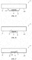
- FIG. 16 is a cross-sectional side view of device 10 in a configuration in which solenoid 14 has been mounted flush with the outer surface of housing 62.
- inner surface 14' of solenoid 14, which faces housing 62 may be flush with the outwardly facing (external) surface 62R of the planar rear housing wall of housing 62.
- FIG. 17 shows how a portion such as region 62R' of rear housing surface 62R may be recessed below the rest of rear surface 62R.
- Inner solenoid surface 14' may be flush with recessed surface 62R and may therefore cause inner surface 14' to be recessed with respect to planar portions of some or all of rear surface 62R.
- Recessing solenoid 14 as shown in FIG. 17 may help enhance the aesthetics of device 10.
- Recesses e.g., notches
- housing 62 does not hinder magnetic field coupling with solenoid 14.
- solenoid 14 may be mounted on or adjacent to the interior surface of rear housing wall 62R (e.g., when all of wall 62R or a window in wall 62R are formed from plastic, glass, sapphire or other crystalline materials, or other dielectric materials). As when mounted in configurations on the outer surface of wall 62R, solenoid 14 may extend across the rear face of device 10 (e.g., solenoid 14 may be a strip-shaped solenoid that lies in a plane parallel to the exterior surface of rear housing wall 62R).
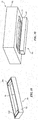
- solenoid 36 may be mounted in cradle 90 in device 12.
- Cradle 90 may have support structure 92 such as a copper cradle structure, other metal cradle structures, or other support structures.
- Solenoid 36 may be a linear solenoid, a U-shaped solenoid, a C-shaped solenoid, or may have other suitable solenoid configurations.
- Support structure 92 may form part of a puck, stand, charging mat, or other wireless power transmitting device 12.
- solenoid 36 has been configured so that solenoid end portions 36E lie on opposing ends of cavity (recess) 94 (e.g., solenoid 36 of FIG. 18 has a U-shape or a C-shape).
- Cavity 94 has been configured to receive solenoid 14 of device 10, as shown by in the perspective view of device 10 and cradle 90 of FIG. 19 .
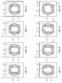
- FIGS. 23, 24, 25, 26, 27, 28, 29, and 30 Additional illustrative configurations for solenoid 14 are shown in FIGS. 23, 24, 25, 26, 27, 28, 29, and 30 .
- first and second sets of turns of wire 14W are formed on first and second respective portions of core 14C. This creates first and second solenoid portions for solenoid 14, which can be operated together (e.g., in series) or independently (e.g., by switching a solenoid portion having a higher coupling efficiency into use while switching a solenoid portion with lower coupling efficiency out of use, etc.).
- a wireless power receiving device having opposing front and rear faces, the wireless power receiving device is configured to receive wireless power signals from a wireless power transmitting device, the wireless power receiving device is provided that a housing having a rear housing wall at the rear face, a display mounted in the housing at the front face, and a solenoid that extends across at least part of the rear face and that is configured to receive the wireless power signals.
- the conductive wire includes a conductive wire selected from the group consisting of: a metal strand with a dielectric coating, a metal strand with a magnetic coating, a metal strand with a rectangular cross-sectional shape, and a conductive wire formed from multiple intertwined metal strands.
- the metal housing has sidewalls coupled to the rear housing wall, the wrist strap is coupled to the sidewalls, and the solenoid extends parallel to the sidewalls to which the wrist strap is coupled and perpendicular to the wrist strap.
- the wireless power transmitting device includes magnets that are configured to attract the wireless power transmitting device.
- the wireless power transmitting device includes a U-shaped core of magnetic material wrapped with wire.
- the wireless power transmitting device includes a C-shaped core of magnetic material wrapped with wire.
- a wireless power receiving device that has opposing front and rear faces and that is configured to receive wireless power signals from a wireless power transmitting device, the wireless power receiving device is provided that includes a housing having a metal rear housing wall at the rear face, a display at the front face that is mounted in the housing, a wrist strap coupled to the housing, and a solenoid supported by the metal rear housing wall that is configured to receive the wireless power signals.
- the solenoid includes a strip-shaped core wrapped with wire and the strip-shaped core extends perpendicularly to the wrist strap.
- the metal rear housing wall has an external surface
- the solenoid has an inner surface facing the external surface
- the inner surface is separated from the external surface by a gap that is filled with dielectric.
- the metal rear housing wall has an external surface
- the solenoid has an inner surface facing the external surface, and the inner surface is flush with the external surface
- the metal rear housing wall has an external surface and the solenoid has an inner surface that lies flush with a recessed portion of the external surface.
Landscapes
- Engineering & Computer Science (AREA)
- Power Engineering (AREA)
- Computer Networks & Wireless Communication (AREA)
- Physics & Mathematics (AREA)
- Electromagnetism (AREA)
- Theoretical Computer Science (AREA)
- Human Computer Interaction (AREA)
- General Engineering & Computer Science (AREA)
- General Physics & Mathematics (AREA)
- Charge And Discharge Circuits For Batteries Or The Like (AREA)
Priority Applications (2)
| Application Number | Priority Date | Filing Date | Title |
|---|---|---|---|
| EP22193562.0A EP4120509A1 (de) | 2016-10-31 | 2017-10-25 | Drahtlose stromempfangseinrichtung |
| EP20192515.3A EP3761480B1 (de) | 2016-10-31 | 2017-10-25 | Drahtlose stromempfangseinrichtung |
Applications Claiming Priority (2)
| Application Number | Priority Date | Filing Date | Title |
|---|---|---|---|
| US201662415348P | 2016-10-31 | 2016-10-31 | |
| US15/491,893 US20180123392A1 (en) | 2016-10-31 | 2017-04-19 | Wireless Charging System With Solenoids |
Related Child Applications (2)
| Application Number | Title | Priority Date | Filing Date |
|---|---|---|---|
| EP22193562.0A Division EP4120509A1 (de) | 2016-10-31 | 2017-10-25 | Drahtlose stromempfangseinrichtung |
| EP20192515.3A Division EP3761480B1 (de) | 2016-10-31 | 2017-10-25 | Drahtlose stromempfangseinrichtung |
Publications (2)
| Publication Number | Publication Date |
|---|---|
| EP3316445A2 true EP3316445A2 (de) | 2018-05-02 |
| EP3316445A3 EP3316445A3 (de) | 2018-06-20 |
Family
ID=60190634
Family Applications (3)
| Application Number | Title | Priority Date | Filing Date |
|---|---|---|---|
| EP20192515.3A Active EP3761480B1 (de) | 2016-10-31 | 2017-10-25 | Drahtlose stromempfangseinrichtung |
| EP22193562.0A Withdrawn EP4120509A1 (de) | 2016-10-31 | 2017-10-25 | Drahtlose stromempfangseinrichtung |
| EP17198421.4A Withdrawn EP3316445A3 (de) | 2016-10-31 | 2017-10-25 | System mit magneten zum drahtlosen laden |
Family Applications Before (2)
| Application Number | Title | Priority Date | Filing Date |
|---|---|---|---|
| EP20192515.3A Active EP3761480B1 (de) | 2016-10-31 | 2017-10-25 | Drahtlose stromempfangseinrichtung |
| EP22193562.0A Withdrawn EP4120509A1 (de) | 2016-10-31 | 2017-10-25 | Drahtlose stromempfangseinrichtung |
Country Status (6)
| Country | Link |
|---|---|
| US (3) | US20180123392A1 (de) |
| EP (3) | EP3761480B1 (de) |
| JP (2) | JP2018074900A (de) |
| KR (3) | KR101987380B1 (de) |
| CN (3) | CN207353911U (de) |
| AU (2) | AU2017101347C4 (de) |
Families Citing this family (34)
| Publication number | Priority date | Publication date | Assignee | Title |
|---|---|---|---|---|
| KR102284906B1 (ko) * | 2017-03-07 | 2021-08-04 | 주식회사 위츠 | 자성체의 제조 방법 및 이를 포함하는 무선 통신 안테나의 제조 방법 |
| US10965162B2 (en) * | 2018-05-08 | 2021-03-30 | Apple Inc. | Wireless power systems |
| CN108711946A (zh) * | 2018-08-02 | 2018-10-26 | 宁波微鹅电子科技有限公司 | 一种电能发射装置、充电系统、及充电套装 |
| KR102235490B1 (ko) * | 2018-08-20 | 2021-04-02 | 애플 인크. | 전자 디바이스를 위한 무선 충전 시스템 |
| CN108767993A (zh) * | 2018-08-22 | 2018-11-06 | 深圳市和宏实业股份有限公司 | 一种地毯式无线充电器 |
| CN109256868B (zh) * | 2018-09-29 | 2020-11-06 | 深圳市华禹无线供电技术有限公司 | 双接收端功率可配置的非接触式供电系统及功率配置方法 |
| CN109888860A (zh) * | 2019-01-28 | 2019-06-14 | 努比亚技术有限公司 | 一种无线充电模组、终端及充电器 |
| JP6705924B1 (ja) * | 2019-03-04 | 2020-06-03 | パナソニックi−PROセンシングソリューションズ株式会社 | 電子機器 |
| KR102243431B1 (ko) * | 2019-03-13 | 2021-04-22 | 임성규 | 비주얼 디지털 장신구 장치 |
| US11251656B2 (en) * | 2019-04-03 | 2022-02-15 | Apple Inc. | Coils for wireless power systems |
| US11757307B2 (en) | 2020-01-03 | 2023-09-12 | Nucurrent, Inc. | Systems and methods for dynamically tuning a wireless power transfer system |
| US11375973B2 (en) * | 2020-05-11 | 2022-07-05 | GE Precision Healthcare LLC | Methods and systems for wirelessly charging digital x-ray detectors |
| US11303164B2 (en) | 2020-07-24 | 2022-04-12 | Nucurrent, Inc. | Low cost communications demodulation for wireless power transmission system |
| US11303165B2 (en) | 2020-07-24 | 2022-04-12 | Nucurrent, Inc. | Low cost communications demodulation for wireless power receiver system |
| US12355527B2 (en) | 2021-01-28 | 2025-07-08 | Nucurrent, Inc. | High speed data communications system for industrial use in packaged goods |
| US11476898B2 (en) | 2021-01-28 | 2022-10-18 | Nucurrent, Inc. | Wireless power transfer system with mode switching using selective quality factor alteration |
| US11483033B2 (en) | 2021-01-28 | 2022-10-25 | Nucurrent, Inc. | Wireless power transfer system with data versus power priority optimization |
| US11271611B1 (en) | 2021-01-28 | 2022-03-08 | Nucurrent, Inc. | Wireless power transfer with in-band virtualized wired communications |
| US11811244B2 (en) | 2021-02-01 | 2023-11-07 | Nucurrent, Inc. | Automatic gain control for communications demodulation in wireless power transmitters |
| US11289952B1 (en) | 2021-02-10 | 2022-03-29 | Nucurrent, Inc. | Slotted communications in virtual AC power signal transfer with variable slot width |
| US11532956B2 (en) | 2021-04-30 | 2022-12-20 | Nucurrent, Inc. | Power capability detection with verification load in power level control systems for wireless power transmission |
| US11539247B2 (en) | 2021-04-30 | 2022-12-27 | Nucurrent, Inc. | Power capability detection in precision power level control systems for wireless power transmission |
| US12476497B2 (en) * | 2021-06-23 | 2025-11-18 | Apple Inc. | Wireless power systems with magnetic alignment systems |
| CN113258686B (zh) * | 2021-06-29 | 2021-09-21 | 信维通信(江苏)有限公司 | 高功率防磁漏手机无线充电系统及磁力定位系统 |
| CN113534653A (zh) * | 2021-07-28 | 2021-10-22 | 深圳市新科盈数码有限公司 | 一种具备定位功能的智能手表 |
| US12170549B2 (en) * | 2021-10-08 | 2024-12-17 | Nucurrent, Inc. | Heat diffuser in wrist worn wireless power and data system |
| US11637448B1 (en) | 2021-10-12 | 2023-04-25 | Nucurrent, Inc. | Wireless power transmitter with removable magnetic connector panel for vehicular use |
| US11626756B1 (en) | 2021-10-15 | 2023-04-11 | Nucurrent, Inc. | Wireless power and data transfer system with out of band communications hand off |
| US12231187B2 (en) | 2021-10-15 | 2025-02-18 | Nucurrent, Inc. | High speed data communications system for industrial use in packaged goods with out of band communications hand off |
| US11754618B2 (en) | 2021-10-15 | 2023-09-12 | Nucurrent, Inc. | Testing device for electronic devices with in-band virtualized wired communications |
| CN119817022A (zh) * | 2022-09-05 | 2025-04-11 | 现代自动车株式会社 | 用于无线电力传输的磁芯结构、以及使用磁芯结构的无线电力传输装置和方法 |
| US12476492B2 (en) | 2022-09-13 | 2025-11-18 | Nucurrent, Inc. | Bit stuffing for thermal mitigation in wireless power and data transfer system |
| US12573883B2 (en) | 2022-09-13 | 2026-03-10 | Nucurrent, Inc. | Bit inversion for thermal mitigation in wireless power and data transfer system |
| WO2025048772A1 (en) * | 2023-08-25 | 2025-03-06 | Maisy Leigh Productions LLC | Decouplable charger puck with support and desk mat ecosystem and methods of manufacturing and using same |
Family Cites Families (57)
| Publication number | Priority date | Publication date | Assignee | Title |
|---|---|---|---|---|
| JPS5062073A (de) * | 1973-10-01 | 1975-05-27 | ||
| JPS6399511A (ja) * | 1986-06-17 | 1988-04-30 | Tokyo Keiki Co Ltd | 磁気誘導結合装置 |
| EP0298707B1 (de) * | 1987-07-10 | 1994-09-28 | Seiko Epson Corporation | Ladevorrichtung für elektronisches Gerät |
| US4912391A (en) * | 1989-05-01 | 1990-03-27 | Motorola, Inc. | Flux-coupled iron directed battery charger |
| JPH08181026A (ja) * | 1994-12-22 | 1996-07-12 | Matsushita Electric Works Ltd | 非接触電力伝達装置 |
| JPH104639A (ja) * | 1996-06-14 | 1998-01-06 | Tdk Corp | 携帯用通信機 |
| JPH10225020A (ja) * | 1997-02-03 | 1998-08-21 | Sony Corp | 無接点電力供給装置 |
| TW463399B (en) * | 1999-03-19 | 2001-11-11 | Seiko Epson Corp | Electronic device |
| JP2001110658A (ja) * | 1999-10-04 | 2001-04-20 | Aichi Electric Co Ltd | 非接触給電装置 |
| JP3706022B2 (ja) * | 2000-12-27 | 2005-10-12 | 東光株式会社 | 非接触充電器 |
| EP1506605A2 (de) * | 2002-05-13 | 2005-02-16 | Splashplower Limited | Berührungslose leistungsübertragung |
| JP2004194400A (ja) * | 2002-12-10 | 2004-07-08 | Aichi Electric Co Ltd | 非接触電源装置 |
| JP4064333B2 (ja) * | 2003-10-31 | 2008-03-19 | 米沢電線株式会社 | 無接点充電式機器および充電器 |
| US7211986B1 (en) | 2004-07-01 | 2007-05-01 | Plantronics, Inc. | Inductive charging system |
| US7271569B2 (en) * | 2004-09-21 | 2007-09-18 | Motorola Inc. | Contact less charger with alignment indicator |
| US7443362B2 (en) * | 2005-07-19 | 2008-10-28 | 3M Innovative Properties Company | Solenoid antenna |
| JP2007149946A (ja) * | 2005-11-28 | 2007-06-14 | Hitachi Plant Technologies Ltd | 可飽和リアクトル及び該可飽和リアクトルを用いた非接触給電装置 |
| US8169185B2 (en) * | 2006-01-31 | 2012-05-01 | Mojo Mobility, Inc. | System and method for inductive charging of portable devices |
| JP2007301177A (ja) * | 2006-05-11 | 2007-11-22 | Olympus Corp | 無線電力受電装置 |
| JP4725611B2 (ja) * | 2008-07-16 | 2011-07-13 | セイコーエプソン株式会社 | 送電制御装置、送電装置、受電制御装置、受電装置及び電子機器 |
| EP2381532B1 (de) * | 2008-12-19 | 2018-09-05 | Hitachi Metals, Ltd. | Resonante empfangsantenne und empfangsvorrichtung |
| JP2010219330A (ja) * | 2009-03-17 | 2010-09-30 | Ricoh Elemex Corp | 非接触エネルギー伝送装置の1次側コイルと2次側コイル、非接触エネルギー伝送装置のコイル条件決定方法 |
| JP2011114911A (ja) * | 2009-11-25 | 2011-06-09 | Ricoh Elemex Corp | 充電制御装置および電子時計 |
| US20110133726A1 (en) | 2009-12-09 | 2011-06-09 | Alexander Ballantyne | Precision alignment system |
| JP2011160501A (ja) * | 2010-01-29 | 2011-08-18 | Casio Computer Co Ltd | 電子機器 |
| KR20130099071A (ko) | 2010-08-25 | 2013-09-05 | 액세스 비지니스 그룹 인터내셔날 엘엘씨 | 무선 전원 공급 시스템 및 다층 심 조립체 |
| JP5562804B2 (ja) * | 2010-11-02 | 2014-07-30 | 昭和飛行機工業株式会社 | インダクタンス可変の非接触給電装置 |
| WO2012064871A2 (en) * | 2010-11-09 | 2012-05-18 | California Institute Of Technology | Ferromagnetic cores of amorphouse ferromagnetic metal alloys and electonic devices having the same |
| US8729854B2 (en) * | 2011-10-18 | 2014-05-20 | Fu Da Tong Technology Co., Ltd. | Slot-type induction charger |
| KR101371058B1 (ko) | 2011-12-07 | 2014-03-10 | 한양대학교 산학협력단 | 전기 공진을 이용한 송전측 코일조립체, 수전측 코일조립체 및 무선 전력 송수신장치 |
| US9325187B2 (en) | 2012-05-21 | 2016-04-26 | Lg Electronics Inc. | Structure of transmission and reception unit in wireless charging system |
| DE102012209898A1 (de) * | 2012-06-13 | 2013-12-19 | Siemens Aktiengesellschaft | Anordnung zur induktiven drahtlosen Abgabe von Energie |
| JP5776638B2 (ja) * | 2012-06-29 | 2015-09-09 | トヨタ自動車株式会社 | 非接触電力伝送用コイルユニット、受電装置、車両、および送電装置 |
| JP6300107B2 (ja) * | 2013-01-30 | 2018-03-28 | パナソニックIpマネジメント株式会社 | 非接触電力伝送装置 |
| JP5687719B2 (ja) * | 2013-01-31 | 2015-03-18 | トヨタ自動車株式会社 | 受電装置、送電装置および電力伝送システム |
| JP2014175865A (ja) * | 2013-03-08 | 2014-09-22 | Nucurrent Inc | 高効率の無線通信用多層多巻き構造 |
| JP6546371B2 (ja) * | 2013-03-14 | 2019-07-17 | 矢崎総業株式会社 | コイルユニット及び非接触給電装置 |
| US9837846B2 (en) | 2013-04-12 | 2017-12-05 | Mojo Mobility, Inc. | System and method for powering or charging receivers or devices having small surface areas or volumes |
| US9601267B2 (en) * | 2013-07-03 | 2017-03-21 | Qualcomm Incorporated | Wireless power transmitter with a plurality of magnetic oscillators |
| JP6123607B2 (ja) * | 2013-09-24 | 2017-05-10 | トヨタ自動車株式会社 | 車両 |
| US10020683B2 (en) * | 2013-10-31 | 2018-07-10 | Qualcomm Incorporated | Systems, apparatus, and method for a dual mode wireless power receiver |
| JP6249731B2 (ja) * | 2013-11-19 | 2017-12-20 | 矢崎総業株式会社 | コイルユニット及び非接触電力伝送装置 |
| KR20150067673A (ko) | 2013-12-10 | 2015-06-18 | 엘지전자 주식회사 | 무선 충전 장치 |
| DE102013225875A1 (de) * | 2013-12-13 | 2015-07-02 | Siemens Aktiengesellschaft | Führung eines magnetischen Flusses |
| EP3379549B1 (de) * | 2014-03-24 | 2020-10-21 | Apple Inc. | Magnetische verbindung und ausrichtung verbindlicher geräte |
| US10320230B2 (en) * | 2014-03-26 | 2019-06-11 | Apple Inc. | Temperature management for inductive charging systems |
| US9449754B2 (en) * | 2014-05-30 | 2016-09-20 | Apple Inc. | Coil constructions for improved inductive energy transfer |
| US9583256B2 (en) * | 2014-06-13 | 2017-02-28 | Verily Life Sciences Llc | Three-dimensional wireless charging coil |
| CN104092060B (zh) * | 2014-06-17 | 2016-03-30 | 慈溪市明业通讯电子有限公司 | 一种安装于桌面的多功能插线板 |
| US9460846B2 (en) * | 2014-06-20 | 2016-10-04 | Apple Inc. | Methods for forming shield materials onto inductive coils |
| US20160064137A1 (en) * | 2014-09-02 | 2016-03-03 | Apple Inc. | Capacitively balanced inductive charging coil |
| KR102231851B1 (ko) * | 2014-09-25 | 2021-03-26 | 삼성전자주식회사 | 하나 이상의 전자 장치들을 충전하는 방법 및 그를 위한 충전 장치 |
| KR20160086685A (ko) * | 2015-01-12 | 2016-07-20 | 엘지전자 주식회사 | 무선 전력 전송방법, 무선 전력 전송장치 및 무선 충전 시스템 |
| JP6430304B2 (ja) * | 2015-03-18 | 2018-11-28 | 株式会社ベルニクス | 非接触給電装置 |
| US20160301241A1 (en) * | 2015-04-09 | 2016-10-13 | Samsung Electro-Mechanics Co., Ltd. | Wireless power receiver and power supply apparatus using the same |
| US9793743B2 (en) * | 2015-07-14 | 2017-10-17 | Tdk Taiwan Corporation | Wireless charging device for charging a plurality of wireless power receiving apparatus and charging method thereof |
| US10734158B2 (en) * | 2015-12-17 | 2020-08-04 | Wits Co., Ltd. | Coil device and apparatus including the same |
-
2017
- 2017-04-19 US US15/491,893 patent/US20180123392A1/en not_active Abandoned
- 2017-10-06 AU AU2017101347A patent/AU2017101347C4/en not_active Expired
- 2017-10-06 AU AU2017239618A patent/AU2017239618B2/en not_active Ceased
- 2017-10-17 JP JP2017200881A patent/JP2018074900A/ja active Pending
- 2017-10-25 KR KR1020170139217A patent/KR101987380B1/ko not_active Expired - Fee Related
- 2017-10-25 EP EP20192515.3A patent/EP3761480B1/de active Active
- 2017-10-25 EP EP22193562.0A patent/EP4120509A1/de not_active Withdrawn
- 2017-10-25 EP EP17198421.4A patent/EP3316445A3/de not_active Withdrawn
- 2017-10-30 CN CN201721420228.1U patent/CN207353911U/zh active Active
- 2017-10-30 CN CN201711034262.XA patent/CN108011451A/zh active Pending
- 2017-10-30 CN CN202010087197.2A patent/CN111371190A/zh active Pending
-
2019
- 2019-06-03 KR KR1020190065451A patent/KR102129866B1/ko not_active Expired - Fee Related
-
2020
- 2020-01-24 JP JP2020009689A patent/JP7021267B2/ja active Active
- 2020-05-11 US US16/872,243 patent/US11303155B2/en active Active
- 2020-06-29 KR KR1020200079081A patent/KR102229959B1/ko active Active
-
2021
- 2021-12-09 US US17/546,808 patent/US11611239B2/en active Active
Non-Patent Citations (1)
| Title |
|---|
| None |
Also Published As
| Publication number | Publication date |
|---|---|
| AU2017101347C4 (en) | 2019-07-04 |
| EP3761480A1 (de) | 2021-01-06 |
| KR102229959B1 (ko) | 2021-03-18 |
| AU2017239618A1 (en) | 2018-05-17 |
| EP4120509A1 (de) | 2023-01-18 |
| AU2017239618B2 (en) | 2019-05-02 |
| KR102129866B1 (ko) | 2020-07-03 |
| EP3761480B1 (de) | 2022-10-05 |
| CN207353911U (zh) | 2018-05-11 |
| CN111371190A (zh) | 2020-07-03 |
| AU2017101347B4 (en) | 2018-07-19 |
| KR20180048335A (ko) | 2018-05-10 |
| US20200343768A1 (en) | 2020-10-29 |
| US11611239B2 (en) | 2023-03-21 |
| JP2020099193A (ja) | 2020-06-25 |
| US11303155B2 (en) | 2022-04-12 |
| JP7021267B2 (ja) | 2022-02-16 |
| JP2018074900A (ja) | 2018-05-10 |
| US20180123392A1 (en) | 2018-05-03 |
| EP3316445A3 (de) | 2018-06-20 |
| KR20200083409A (ko) | 2020-07-08 |
| CN108011451A (zh) | 2018-05-08 |
| KR101987380B1 (ko) | 2019-06-10 |
| US20220103013A1 (en) | 2022-03-31 |
| AU2017101347A4 (en) | 2017-11-09 |
| KR20190065992A (ko) | 2019-06-12 |
Similar Documents
| Publication | Publication Date | Title |
|---|---|---|
| US11611239B2 (en) | Wireless charging system with solenoids | |
| EP2926351B1 (de) | Drahtloses ladesystem für ein handgelenk-getragenes gerät | |
| US10164468B2 (en) | Protective cover with wireless charging feature | |
| EP3425651A3 (de) | Kommunikationsgerät | |
| CN104025423B (zh) | 磁场空间的形成方法 | |
| US20190311848A1 (en) | Inductive power transfer assembly | |
| US20240275206A1 (en) | Wireless charging for devices with metal housings | |
| EP2415627A3 (de) | Elektrisch angetriebenes Fahrzeug und Stromspeisungsvorrichtung für das Fahrzeug | |
| JP2019004628A (ja) | 非接触給電装置 | |
| KR102579078B1 (ko) | 무선 전력 전송 모듈 및 이를 구비하는 전자 기기 | |
| US11251656B2 (en) | Coils for wireless power systems | |
| US11355865B2 (en) | Planar antenna | |
| EP4014299B1 (de) | Doppelseitige induktive ladespule | |
| US10411518B2 (en) | Non-contact transmission device for electronic lock | |
| US20210152020A1 (en) | Power reception device | |
| EP3742579A1 (de) | Zwei-stufige drahtlose energieübertragungssystem |
Legal Events
| Date | Code | Title | Description |
|---|---|---|---|
| PUAI | Public reference made under article 153(3) epc to a published international application that has entered the european phase |
Free format text: ORIGINAL CODE: 0009012 |
|
| STAA | Information on the status of an ep patent application or granted ep patent |
Free format text: STATUS: REQUEST FOR EXAMINATION WAS MADE |
|
| 17P | Request for examination filed |
Effective date: 20171025 |
|
| AK | Designated contracting states |
Kind code of ref document: A2 Designated state(s): AL AT BE BG CH CY CZ DE DK EE ES FI FR GB GR HR HU IE IS IT LI LT LU LV MC MK MT NL NO PL PT RO RS SE SI SK SM TR |
|
| AX | Request for extension of the european patent |
Extension state: BA ME |
|
| PUAL | Search report despatched |
Free format text: ORIGINAL CODE: 0009013 |
|
| AK | Designated contracting states |
Kind code of ref document: A3 Designated state(s): AL AT BE BG CH CY CZ DE DK EE ES FI FR GB GR HR HU IE IS IT LI LT LU LV MC MK MT NL NO PL PT RO RS SE SI SK SM TR |
|
| AX | Request for extension of the european patent |
Extension state: BA ME |
|
| RIC1 | Information provided on ipc code assigned before grant |
Ipc: H01F 38/14 20060101ALI20180517BHEP Ipc: H02J 50/90 20160101ALI20180517BHEP Ipc: H02J 50/10 20160101ALI20180517BHEP Ipc: H02J 7/00 20060101AFI20180517BHEP |
|
| RAP1 | Party data changed (applicant data changed or rights of an application transferred) |
Owner name: APPLE INC. |
|
| STAA | Information on the status of an ep patent application or granted ep patent |
Free format text: STATUS: EXAMINATION IS IN PROGRESS |
|
| 17Q | First examination report despatched |
Effective date: 20200422 |
|
| STAA | Information on the status of an ep patent application or granted ep patent |
Free format text: STATUS: THE APPLICATION IS DEEMED TO BE WITHDRAWN |
|
| 18D | Application deemed to be withdrawn |
Effective date: 20200903 |