EP3313070A1 - Projektionsvorrichtung - Google Patents
Projektionsvorrichtung Download PDFInfo
- Publication number
- EP3313070A1 EP3313070A1 EP17202283.2A EP17202283A EP3313070A1 EP 3313070 A1 EP3313070 A1 EP 3313070A1 EP 17202283 A EP17202283 A EP 17202283A EP 3313070 A1 EP3313070 A1 EP 3313070A1
- Authority
- EP
- European Patent Office
- Prior art keywords
- light
- waveband
- phosphor
- waveband light
- projection apparatus
- Prior art date
- Legal status (The legal status is an assumption and is not a legal conclusion. Google has not performed a legal analysis and makes no representation as to the accuracy of the status listed.)
- Granted
Links
- OAICVXFJPJFONN-UHFFFAOYSA-N Phosphorus Chemical compound [P] OAICVXFJPJFONN-UHFFFAOYSA-N 0.000 claims abstract description 197
- 230000003287 optical effect Effects 0.000 claims abstract description 57
- 238000005286 illumination Methods 0.000 claims abstract description 53
- 238000000926 separation method Methods 0.000 claims description 15
- 239000000203 mixture Substances 0.000 claims description 8
- 239000003795 chemical substances by application Substances 0.000 description 69
- 238000003384 imaging method Methods 0.000 description 30
- 239000004973 liquid crystal related substance Substances 0.000 description 10
- 238000000034 method Methods 0.000 description 6
- 238000001914 filtration Methods 0.000 description 5
- 230000001771 impaired effect Effects 0.000 description 2
- 230000001902 propagating effect Effects 0.000 description 2
- 238000001228 spectrum Methods 0.000 description 2
- 238000011144 upstream manufacturing Methods 0.000 description 2
- XUIMIQQOPSSXEZ-UHFFFAOYSA-N Silicon Chemical compound [Si] XUIMIQQOPSSXEZ-UHFFFAOYSA-N 0.000 description 1
- 230000004075 alteration Effects 0.000 description 1
- 238000006243 chemical reaction Methods 0.000 description 1
- 238000005352 clarification Methods 0.000 description 1
- 238000004519 manufacturing process Methods 0.000 description 1
- 238000012986 modification Methods 0.000 description 1
- 230000004048 modification Effects 0.000 description 1
- 229920006395 saturated elastomer Polymers 0.000 description 1
- 229910052710 silicon Inorganic materials 0.000 description 1
- 239000010703 silicon Substances 0.000 description 1
Images


Classifications
-
- G—PHYSICS
- G03—PHOTOGRAPHY; CINEMATOGRAPHY; ANALOGOUS TECHNIQUES USING WAVES OTHER THAN OPTICAL WAVES; ELECTROGRAPHY; HOLOGRAPHY
- G03B—APPARATUS OR ARRANGEMENTS FOR TAKING PHOTOGRAPHS OR FOR PROJECTING OR VIEWING THEM; APPARATUS OR ARRANGEMENTS EMPLOYING ANALOGOUS TECHNIQUES USING WAVES OTHER THAN OPTICAL WAVES; ACCESSORIES THEREFOR
- G03B21/00—Projectors or projection-type viewers; Accessories therefor
- G03B21/14—Details
- G03B21/20—Lamp housings
- G03B21/2006—Lamp housings characterised by the light source
- G03B21/2033—LED or laser light sources
- G03B21/204—LED or laser light sources using secondary light emission, e.g. luminescence or fluorescence
-
- B—PERFORMING OPERATIONS; TRANSPORTING
- B05—SPRAYING OR ATOMISING IN GENERAL; APPLYING FLUENT MATERIALS TO SURFACES, IN GENERAL
- B05D—PROCESSES FOR APPLYING FLUENT MATERIALS TO SURFACES, IN GENERAL
- B05D5/00—Processes for applying liquids or other fluent materials to surfaces to obtain special surface effects, finishes or structures
- B05D5/06—Processes for applying liquids or other fluent materials to surfaces to obtain special surface effects, finishes or structures to obtain multicolour or other optical effects
-
- F—MECHANICAL ENGINEERING; LIGHTING; HEATING; WEAPONS; BLASTING
- F21—LIGHTING
- F21V—FUNCTIONAL FEATURES OR DETAILS OF LIGHTING DEVICES OR SYSTEMS THEREOF; STRUCTURAL COMBINATIONS OF LIGHTING DEVICES WITH OTHER ARTICLES, NOT OTHERWISE PROVIDED FOR
- F21V13/00—Producing particular characteristics or distribution of the light emitted by means of a combination of elements specified in two or more of main groups F21V1/00 - F21V11/00
- F21V13/02—Combinations of only two kinds of elements
- F21V13/08—Combinations of only two kinds of elements the elements being filters or photoluminescent elements and reflectors
-
- F—MECHANICAL ENGINEERING; LIGHTING; HEATING; WEAPONS; BLASTING
- F21—LIGHTING
- F21V—FUNCTIONAL FEATURES OR DETAILS OF LIGHTING DEVICES OR SYSTEMS THEREOF; STRUCTURAL COMBINATIONS OF LIGHTING DEVICES WITH OTHER ARTICLES, NOT OTHERWISE PROVIDED FOR
- F21V9/00—Elements for modifying spectral properties, polarisation or intensity of the light emitted, e.g. filters
- F21V9/08—Elements for modifying spectral properties, polarisation or intensity of the light emitted, e.g. filters for producing coloured light, e.g. monochromatic; for reducing intensity of light
-
- F—MECHANICAL ENGINEERING; LIGHTING; HEATING; WEAPONS; BLASTING
- F21—LIGHTING
- F21V—FUNCTIONAL FEATURES OR DETAILS OF LIGHTING DEVICES OR SYSTEMS THEREOF; STRUCTURAL COMBINATIONS OF LIGHTING DEVICES WITH OTHER ARTICLES, NOT OTHERWISE PROVIDED FOR
- F21V9/00—Elements for modifying spectral properties, polarisation or intensity of the light emitted, e.g. filters
- F21V9/30—Elements containing photoluminescent material distinct from or spaced from the light source
-
- G—PHYSICS
- G02—OPTICS
- G02B—OPTICAL ELEMENTS, SYSTEMS OR APPARATUS
- G02B27/00—Optical systems or apparatus not provided for by any of the groups G02B1/00 - G02B26/00, G02B30/00
- G02B27/10—Beam splitting or combining systems
- G02B27/1006—Beam splitting or combining systems for splitting or combining different wavelengths
-
- G—PHYSICS
- G02—OPTICS
- G02B—OPTICAL ELEMENTS, SYSTEMS OR APPARATUS
- G02B7/00—Mountings, adjusting means, or light-tight connections, for optical elements
-
- G—PHYSICS
- G03—PHOTOGRAPHY; CINEMATOGRAPHY; ANALOGOUS TECHNIQUES USING WAVES OTHER THAN OPTICAL WAVES; ELECTROGRAPHY; HOLOGRAPHY
- G03B—APPARATUS OR ARRANGEMENTS FOR TAKING PHOTOGRAPHS OR FOR PROJECTING OR VIEWING THEM; APPARATUS OR ARRANGEMENTS EMPLOYING ANALOGOUS TECHNIQUES USING WAVES OTHER THAN OPTICAL WAVES; ACCESSORIES THEREFOR
- G03B21/00—Projectors or projection-type viewers; Accessories therefor
-
- H—ELECTRICITY
- H04—ELECTRIC COMMUNICATION TECHNIQUE
- H04N—PICTORIAL COMMUNICATION, e.g. TELEVISION
- H04N9/00—Details of colour television systems
- H04N9/12—Picture reproducers
- H04N9/31—Projection devices for colour picture display, e.g. using electronic spatial light modulators [ESLM]
- H04N9/3102—Projection devices for colour picture display, e.g. using electronic spatial light modulators [ESLM] using two-dimensional electronic spatial light modulators
- H04N9/3105—Projection devices for colour picture display, e.g. using electronic spatial light modulators [ESLM] using two-dimensional electronic spatial light modulators for displaying all colours simultaneously, e.g. by using two or more electronic spatial light modulators
-
- H—ELECTRICITY
- H04—ELECTRIC COMMUNICATION TECHNIQUE
- H04N—PICTORIAL COMMUNICATION, e.g. TELEVISION
- H04N9/00—Details of colour television systems
- H04N9/12—Picture reproducers
- H04N9/31—Projection devices for colour picture display, e.g. using electronic spatial light modulators [ESLM]
- H04N9/3102—Projection devices for colour picture display, e.g. using electronic spatial light modulators [ESLM] using two-dimensional electronic spatial light modulators
- H04N9/3111—Projection devices for colour picture display, e.g. using electronic spatial light modulators [ESLM] using two-dimensional electronic spatial light modulators for displaying the colours sequentially, e.g. by using sequentially activated light sources
- H04N9/3114—Projection devices for colour picture display, e.g. using electronic spatial light modulators [ESLM] using two-dimensional electronic spatial light modulators for displaying the colours sequentially, e.g. by using sequentially activated light sources by using a sequential colour filter producing one colour at a time
-
- H—ELECTRICITY
- H04—ELECTRIC COMMUNICATION TECHNIQUE
- H04N—PICTORIAL COMMUNICATION, e.g. TELEVISION
- H04N9/00—Details of colour television systems
- H04N9/12—Picture reproducers
- H04N9/31—Projection devices for colour picture display, e.g. using electronic spatial light modulators [ESLM]
- H04N9/3141—Constructional details thereof
- H04N9/315—Modulator illumination systems
- H04N9/3158—Modulator illumination systems for controlling the spectrum
-
- H—ELECTRICITY
- H04—ELECTRIC COMMUNICATION TECHNIQUE
- H04N—PICTORIAL COMMUNICATION, e.g. TELEVISION
- H04N9/00—Details of colour television systems
- H04N9/12—Picture reproducers
- H04N9/31—Projection devices for colour picture display, e.g. using electronic spatial light modulators [ESLM]
- H04N9/3141—Constructional details thereof
- H04N9/315—Modulator illumination systems
- H04N9/3164—Modulator illumination systems using multiple light sources
-
- B—PERFORMING OPERATIONS; TRANSPORTING
- B32—LAYERED PRODUCTS
- B32B—LAYERED PRODUCTS, i.e. PRODUCTS BUILT-UP OF STRATA OF FLAT OR NON-FLAT, e.g. CELLULAR OR HONEYCOMB, FORM
- B32B2307/00—Properties of the layers or laminate
- B32B2307/40—Properties of the layers or laminate having particular optical properties
- B32B2307/422—Luminescent, fluorescent, phosphorescent
Definitions
- the present invention relates to a phosphor device, and more particularly to a phosphor device containing a single phosphor agent.
- the present invention also relates to an illumination system and a projection apparatus with the phosphor device in order to produce three primary color lights.
- the illumination system of the current projector employs a solid-state light-emitting element (e.g. light emitting diode or laser diode) to replace the conventional high intensity discharge (HID) lamp.
- a solid-state light-emitting element e.g. light emitting diode or laser diode
- the illumination system of the projector may emit three primary color lights, i.e. a red light (R), a green light (G) and a blue light (B).
- a red light (R) a green light
- a blue light (B) a blue light
- the blue solid-state light-emitting element has the highest luminous efficiency. Since the red solid-state light-emitting element and the green solid-state light-emitting element have poor luminous efficiency, the red light or the green light may be produced by using a blue solid-state light-emitting element and a wavelength conversion device (e.g. a phosphor wheel).
- a wavelength conversion device e.g. a phosphor wheel
- the uses of the blue solid-state light-emitting element and the phosphor wheel may directly emit the red light or the green light in replace of the red solid-state light-emitting element or the green solid-state light-emitting element. Consequently, the luminous efficiency of the whole illumination system is enhanced and the manufacturing cost of the illumination system is reduced.
- FIG. 1A schematically illustrates the architecture of a conventional projector.
- FIG. 1B schematically illustrates a phosphor wheel used in the illumination system of the projector as shown in FIG. 1A .
- the illumination system of the projector 1 employs a solid-state light-emitting element 11 to emit a blue light to a phosphor wheel 12 with a first section 121, a second section 122 and a third section 123.
- the first section 121 is coated with a green phosphor agent.
- the incident blue light is converted to a green light.
- the second section 122 is coated with a red phosphor agent.
- the red phosphor agent the incident blue light is converted to a red light.
- the third section 123 is a transparent section. The blue light is transmitted through the third section 123. In other words, the blue light from the solid-state light-emitting element 11 is directly transmitted through the phosphor wheel 12 or converted into the green light or the red light by the phosphor wheel 12. Consequently, three primary color lights can be produced. Moreover, the three primary color lights are directed to an imaging device 14 through a relay module 13.
- the imaging device 14 is a digital micromirror device (DMD), a liquid crystal display (LCD) device or a liquid crystal on silicon (LCoS) device. After being scaled up/down and focused by a lens group 15, an image is projected on a display screen 16.
- DMD digital micromirror device
- LCD liquid crystal display
- LCDoS liquid crystal on silicon
- FIG. 2A schematically illustrates the architecture of another conventional projector.
- FIG. 2B schematically illustrates a first phosphor wheel used in the illumination system of the projector as shown in FIG. 2A .
- FIG. 2C schematically illustrates a second phosphor wheel used in the illumination system of the projector as shown in FIG. 2A . Please refer to FIGS. 2A , 2B and 2C .
- a section 221 of a first phosphor wheel 22 is coated with a red phosphor agent
- a section 241 of a second phosphor wheel 24 is coated with a green phosphor agent.
- the projector 2 further comprises a first dichroic mirror 210 and a second dichroic mirror 211, a first solid-state light-emitting element 21, a second solid-state light-emitting element 23, and a third solid-state light-emitting element 25.
- the red light is permitted to be transmitted through the first dichroic mirror 210, but the green light is reflected by the first dichroic mirror 210.
- the red light and the green light are permitted to be transmitted through the second dichroic mirror 211, but the blue light is reflected by the second dichroic mirror 211.
- the blue light from the first solid-state light-emitting element 21 is converted to a red light by the first phosphor wheel 22.
- the red light is transmitted through the first dichroic mirror 210 and the second dichroic mirror 211 and directed to a relay module 26.
- the blue light from the second solid-state light-emitting element 23 is converted to a green light by the second phosphor wheel 24.
- the green light is sequentially reflected by the first dichroic mirror 210, transmitted through the second dichroic mirror 211 and directed to the relay module 26.
- the blue light from the third solid-state light-emitting element 25 is reflected by the second dichroic mirror 211 and directed to the relay module 26.
- the three primary color lights are sequentially or simultaneously directed to an imaging device 27 through the relay module 26. After being scaled up/down and focused by a lens group 28, an image is projected on a display screen 29.
- the uses of the blue solid-state light-emitting element and the phosphor wheel may directly emit the red light or the green light in replace of the red solid-state light-emitting element or the green solid-state light-emitting element.
- the green light converted by the green phosphor agent contains a portion of a red light, the green light looks somewhat yellowish. That is, the color purity is insufficient, and thus the imaging quality is impaired.
- the exciting efficiency of red phosphor is lower and easier saturated than the green phosphor, the total amount of red light converted from the red phosphor agent is insufficient.
- the red light converted by the red phosphor agent quickly saturates or even decay. Under this circumstance, the luminance and brightness of the red light is too low, and the bright/dark status of the illumination system fails to be effectively controlled. Consequently, the overall amount of the output light is limited.
- the present invention provides an illumination system and a projection apparatus with a single phosphor device in order to reduce the fabricating cost, simplify the fabricating process, reduce the overall product volume, increase the overall luminance, increase the color purity and enhance the imaging quality.
- the present invention also provides an illumination system and a projection apparatus with a single phosphor device.
- a first waveband light is converted into a third waveband light with a wider waveband.
- the driving current of the blue solid-state light-emitting element increases, the possibility of attenuating the red light will be reduced. Consequently, the overall luminance and brightness will be increased, and the color performance is enhanced.
- a phosphor device of an illumination system emits a first waveband light and has an optical path.
- the phosphor device includes a first section and a first phosphor agent.
- the first phosphor agent is coated on the first section. After the first waveband light is received by the first phosphor agent, the first waveband light is converted into a third waveband light, and the third waveband light is directed to the optical path, so that the third waveband light is separated into at least two color lights along the optical path.
- an illumination system in accordance with another aspect of the present invention, there is provided an illumination system.
- the illumination system includes a phosphor device and a first solid-state light-emitting element.
- the phosphor device includes a first section and a first phosphor agent coated on the first section.
- the first solid-state light-emitting element is used for emitting a first waveband light to the phosphor device.
- the first waveband light is converted into a third waveband light by the phosphor device, and the third waveband light is directed to an optical path and separated into at least two color lights along the optical path.
- the projection apparatus includes an illumination system and an image processing device.
- the illumination system includes a phosphor device, a first solid-state light-emitting element, and a second solid-state light-emitting element.
- the phosphor device includes a first section and a first phosphor agent coated on the first section.
- the first solid-state light-emitting element is used for emitting a first waveband light to the phosphor device.
- the first waveband light is converted into a third waveband light by the phosphor device, and the third waveband light is directed to an optical path.
- the second solid-state light-emitting element is used for emitting a second waveband light to the optical path.
- the image processing device is arranged along the optical path for receiving the third waveband light and the second waveband light.
- the third waveband light is separated into at least two color lights by the image processing device, so that the at least two color lights and the second waveband light are projected as an image in a color separation or time division manner.
- FIG. 3 schematically illustrates the concept of a projection apparatus with a phosphor device according to an embodiment of the present invention.
- the phosphor device 40 is used in an illuminating system that emits a first waveband light L1 and has an optical path P.
- the phosphor device 40 comprises a first section 401 and a first phosphor agent 402 (see FIG. 6A ).
- the first section 401 is coated with the first phosphor agent 402.
- the first waveband light L1 is converted into a third waveband light L3, and the third waveband light L3 is directed to an image processing device 5 along the optical path P.
- the image processing device 5 a color separation process is performed to separate the third waveband light L3 into a first color light C1 and a second color light C2.
- FIG. 4A schematically illustrates the concept of a projection apparatus with a phosphor device according to another embodiment of the present invention.
- FIG. 4B schematically illustrates the structure of the phosphor device of FIG. 4A .
- the phosphor device 45 comprises a first section 451 and a transparent section 452.
- the central angle of the transparent section 452 is smaller than the central angle of the first section 451.
- the first section 451 is coated with a first phosphor agent.
- the first phosphor agent is not shown in the drawings.
- a portion of the first waveband light L1 from the illuminating system is partially transmitted through the transparent section 452 of the phosphor device 45 and directed to an image processing device 5 along the optical path.
- the third waveband light L3 is also directed to the image processing device 5 along the optical path.
- a color separation process is performed to separate the first waveband light L1 and the third waveband light L3 into at least two color lights.
- the at least two color lights and the first waveband light L1 constitute three primary color lights. For example, if the first waveband light L1 is a blue light, the at least two color lights comprise a red light and a green light.
- the first waveband light L1 and the third waveband light L3 from the phosphor device 45 comprise the fractions of three primary color lights, which may be equivalent to a white light.
- the image processing device 5 the first waveband light L1 and the third waveband light L3 are subject to color separation or time division, and thus the three primary color lights are projected in a color separation or time division manner.
- the first waveband light L1 is a blue light
- the third waveband light L3 is a yellow light, a green light or a yellow-green light.
- the first phosphor agent on the first section 451 of the phosphor device 45 is a green phosphor agent, a yellow phosphor agent or a yellow-green phosphor agent. Consequently, the first waveband light L1 (i.e. the blue light) and the third waveband light L3 (i.e. the yellow light, the green light or the yellow-green light) are directed from the phosphor device 45 to the image processing device 5. Since the third waveband light L3 (i.e.
- the yellow light, the green light or the yellow-green light covers the waveband of the green light and the red light, after the color separation process is performed on the third waveband light L3, the third waveband light L3 is separated into a green light G and a red light R. Consequently, the green light G, the red light R and the first waveband light L1 (i.e. the blue light) may be projected in the color separation or time division manner.
- FIG. 5A schematically illustrates a projection apparatus according to an embodiment of the present invention.
- FIG. 5B schematically illustrates a projection apparatus according to another embodiment of the present invention.
- FIG. 6A is a phosphor device used in the projection apparatus of FIG. 5A or FIG. 5B .
- the projection apparatus 3 comprises an illuminating system 4, an image processing device 5, and a lens group 6.
- the illuminating system 4 comprises a phosphor device 40, a first solid-state light-emitting element 41, and a second solid-state light-emitting element 42.
- the image processing device 5 and the lens group 6 are arranged along an optical path.
- the image processing device 5 comprises at least one color-separating element
- the lens group 6 comprises at least one lens.
- the image processing device 5 comprises a relay module 51 and an imaging module 52.
- the relay module 51 is located upstream of the imaging module 52. After being scaled up/down and focused by the lens group 6, an image is projected on a display screen 7.
- the relay module 51 may include a relay lens, a homogenizer or a reflective mirror (not shown).
- the phosphor device 40 includes but is not limited to a phosphor wheel or a phosphor plate.
- the phosphor device 40 has a first section 401 containing a first phosphor agent 402.
- the first phosphor agent 402 is coated on the first section 401.
- the first phosphor agent 402 is a green phosphor agent, a yellow phosphor agent or a yellow-green phosphor agent.
- the first solid-state light-emitting element 41 is used for emitting a first waveband light L1 to the phosphor device 40.
- the second solid-state light-emitting element 42 is used for emitting a second waveband light L2 to the optical path.
- the first solid-state light-emitting element 41 and the second solid-state light-emitting element 42 are blue solid-state light-emitting elements or blue laser diodes for emitting the blue light (e.g. the first waveband light L1). That is, the first waveband light L1 is a light within the spectrum of a blue waveband. In some embodiments, the first waveband light L1 is a UV light. The first waveband light L1 and the second waveband light L2 are lights within the same waveband or different wavebands. By the phosphor device 40, the first waveband light L1 from the first solid-state light-emitting element 41 is converted into a third waveband light L3.
- the third waveband light L3 is a yellow-green light which covers a green waveband and a red waveband.
- the third waveband light L3 is a green light within a green waveband between 450nm and 710nm.
- the light within the waveband between 450nm and 710nm and the blue light (L2) are used in the rear-ended optical path to produce the three primary color lights.
- the first waveband light L1 within the blue waveband is converted into the third waveband light L3, which is a yellow-green light which covers a green waveband and a red waveband.
- the third waveband light L3 is directed to the optical path.
- a color separation process is performed to separate the third waveband light L3 into at least two color lights by the image processing device 5. Consequently, the at least two color lights and the second waveband light L2 are projected as an image in a color separation or time division manner.
- the phosphor device 40 issues the third waveband light L3 to the optical path. After the second waveband light L2 and the third waveband light L3 are received by the image processing device 5, the third waveband light L3 is separated into at least two color lights.
- the primary color lights included in the second waveband light L2 and the third waveband light L3 are projected as an image in a color separation or time division manner.
- the illuminating system 4 only includes a single phosphor device 40, the overall volume of the illuminating system 4 or the projection apparatus 3 is reduced, the fabricating process is simplified, and the fabricating cost is reduced.
- the color purity and the imaging quality are enhanced.
- the first waveband light L1 is converted into the third waveband light L3 with a wider waveband. As the driving current of the blue solid-state light-emitting element increases, the possibility of attenuating the red light will be reduced. Consequently, the overall luminance and brightness of the projection apparatus 3 will be increased, and the color performance is enhanced.
- the illuminating system 4 further comprises a dichroic element 43 (e.g. a dichroic mirror).
- the dichroic element 43 is arranged at the front-ended optical path for assisting in introducing the third waveband light L3 and the second waveband light L2 into the optical path.
- the phosphor device 40, the first solid-state light-emitting element 41 and the second solid-state light-emitting element 42 may be applied to a transmissive illumination system or a reflective illumination system.
- the illumination system as shown in FIG. 5A is a transmissive illumination system.
- the third waveband light L3 is permitted to be transmitted through the dichroic element 43, but the second waveband light L2 is reflected by the dichroic element 43.
- the phosphor device 40 and the first solid-state light-emitting element 41 are located at a first side of the dichroic element 43.
- the phosphor device 40 is located along the optical path, and arranged between the first solid-state light-emitting element 41 and the dichroic element 43. By the phosphor device 40, the first waveband light L1 from the first solid-state light-emitting element 41 is converted into the third waveband light L3.
- the third waveband light L3 is transmitted through the dichroic element 43 and directed to the image processing device 5 and the lens group 6 at the rear end of the optical path.
- the incident direction of the first waveband light L1 is identical to the emergence direction of the third waveband light L3.
- the second solid-state light-emitting element 42 is located at a second side of the dichroic element 43.
- the second solid-state light-emitting element 42 is used for emitting the second waveband light L2 to the dichroic element 43.
- the second waveband light L2 is reflected by the dichroic element 43 and directed to the image processing device 5 and the lens group 6 at the rear end of the optical path.
- the dichroic element 43 may be designed to allow the second waveband light L2 to be transmitted through but reflect the third waveband light L3. Under this circumstance, the second waveband light L2 and the third waveband light L3 are also directed to the image processing device 5 and the lens group 6 at the rear end of the optical path.
- the illumination system as shown in FIG. 5B is a reflective illumination system.
- the second waveband light L2 is permitted to be transmitted through the dichroic element 43, but the third waveband light L3 is reflected by the dichroic element 43.
- the first solid-state light-emitting element 41 and the second solid-state light-emitting element 42 are both located at a first side of the dichroic element 43.
- the phosphor device 40 is located at a second side of the dichroic element 43.
- the first waveband light L1 from the first solid-state light-emitting element 41 is directly transmitted through the dichroic element 43 and directed to the phosphor device 40.
- the second waveband light L2 from the second solid-state light-emitting element 42 is transmitted through the dichroic element 43 and directed to the image processing device 5 and the lens group 6 at the rear end of the optical path. Moreover, after the first waveband light L1 from the first solid-state light-emitting element 41 is received by the phosphor device 40, the first waveband light L1 is converted into the third waveband light L3. The third waveband light L3 is directed to the dichroic element 43 in a direction reverse to the first waveband light L1. In other words, the incident direction of the first waveband light L1 is reverse to the emergence direction of the third waveband light L3 with respect to the phosphor device 40. Then, the third waveband light L3 is reflected by the dichroic element 43 and directed to the image processing device 5 and the lens group 6 at the rear end of the optical path.
- the first waveband light L1 is converted into a third waveband light L3.
- the third waveband light L3 is a yellow-green light within a waveband between 450nm and 710nm.
- the color-separating element of the image processing device 5 the third waveband light L3 within the waveband between 450nm and 710nm is separated into a green light and a red light.
- the green light, the red light and the second waveband light L2 i.e. the blue light
- the phosphor device 40 of the illumination system 4 may be modified to have plural sections.
- the additional use of the filter may adjust the luminance and brightness of the green light or the red light.
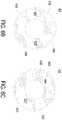
- FIG. 6B is another exemplary phosphor device used in the projection apparatus of FIG. 5A or FIG. 5B .
- FIG. 6C is a further exemplary phosphor device used in the projection apparatus of FIG. 5A or FIG. 5B .
- the phosphor device 40 comprises a first section 401 containing a first phosphor agent 402 and a second section 404 containing a second phosphor agent 405.
- the first phosphor agent 402 is coated on the first section 401.
- the second phosphor agent 405 is coated on the second section 404.
- the first phosphor agent 402 and the second phosphor agent 405 are green phosphor agents, but are not limited thereto.
- the compositions of the first phosphor agent 402 and the second phosphor agent 405 may be identical or different.
- the first waveband light L1 within the blue waveband is converted into the third waveband light L3, which covers a green waveband and a red waveband.
- the compositions of the first phosphor agent 402 and the second phosphor agent 405 are similar or different, the first waveband light L1 within the blue waveband is converted into two kinds of third waveband lights L3 (not shown).
- the two kinds of third waveband lights L3 are time-sequentially directed to the rear end of the illumination system 4.
- the phosphor device 40 further comprises a first color filter 403 and a second color filter 406.
- the first color filter 403 and the second color filter 406 are located at the side of the phosphor device 40 for outputting the third waveband light L3.
- the first color filter 403 and the second color filter 406 are located adjacent to the first section 401 and the second section 404, respectively.
- the first color filter 403 is used for filtering a first light of the third waveband light L3. Consequently, a second light of the third waveband light L3 is transmitted through the first color filter 403 and directed to the optical path.
- the second color filter 406 is used for filtering the second light of the third waveband light L3. Consequently, the first light of the third waveband light L3 is transmitted through the second color filter 406 and directed to the optical path.
- the third waveband light L3 is a yellow-green light within a green waveband and a red waveband
- the first light is a green light
- the second light is a red light.
- the first color filter 403 is used for filtering the green light, so that the red light is transmitted through the first color filter 403 and directed to the optical path.
- the second color filter 406 is used for filtering the red light, so that the green light is transmitted through the second color filter 406 and directed to the optical path.
- the first color filter 403 is a red filter
- the second color filter 406 is a green filter, but is not limited thereto.
- the first color filter 403 and the second color filter 406 may be exchanged in order to change the optical properties (e.g. the luminance or brightness) of the first light or the second light outputted from the phosphor device 40.
- the second section 404 is a transparent region, a light-transmissible region or a reflective region without any phosphor agent.
- FIG. 7A schematically illustrates an exemplary imaging module used in the projection apparatus of the present invention.
- the imaging module 52 of the image processing device 5 is applied to a three-chip LCD projector.
- the imaging module 52 is used for receiving the second waveband light and the third waveband light (i.e. the incident ray I) from the relay module 51.
- the color-separating elements e.g. dichroic filters
- the color lights contained in the incident ray I are separated.
- a first dichroic filter 5201 and a second dichroic filter 5202 are employed to separate the three primary color lights.
- the green light and the red light are permitted to be transmitted through the first dichroic filter 5201, but the blue light is reflected by the first dichroic filter 5201.
- the red light is permitted to be transmitted through the second dichroic filter 5202, but the green light is reflected by the second dichroic filter 5202.
- the blue light fraction of the incident ray I is reflected by the first dichroic filter 5201, reflected by the first reflective mirror 5203, and projected on a first liquid crystal display unit 5204.
- the green light fraction of the incident ray I is transmitted through the first dichroic filter 5201, reflected by the second dichroic filter 5202, and projected on a second liquid crystal display unit 5205.
- the red light fraction of the incident ray I is transmitted through the first dichroic filter 5201 and the second dichroic filter 5202, reflected by a second reflective mirror 5207 and a third reflective mirror 5208, and projected on a third liquid crystal display unit 5206. Afterwards, the image is projected out from a cross dichroic prim (X-Cube) 5209 to the lens group 6 along the rear-ended optical path.
- X-Cube cross dichroic prim
- FIG. 7B schematically illustrates another exemplary imaging module used in the projection apparatus of the present invention.
- the imaging module 52 of the image processing device 5 is applied to a two-chip LCD projector.
- the imaging module 52 also comprises a first liquid crystal display unit 5204, a second liquid crystal display unit 5205, and cross dichroic prim 5209.
- the processes of propagating the incident ray and the blue light fraction are similar to those of FIG. 7A , and are not redundantly described herein.
- the phosphor device with plural sections is employed, and thus plural third waveband lights may be time-sequentially directed to the imaging module 52.
- the green light fraction and the red light fraction of the incident ray are both received by the second liquid crystal display unit 5205, and the green light and the red light are time-sequentially projected on the cross dichroic prim 5209 in a time division manner.
- the images outputted from the first liquid crystal display unit 5204 and the second liquid crystal display unit 5205 are combined together by the cross dichroic prim 5209, and the combined image is directed to the rear-ended optical path.
- FIG. 8A schematically illustrates another exemplary imaging module used in the projection apparatus of the present invention.
- the imaging module 52 of the image processing device 5 is applied to a three-chip digital light processing (DLP) projector.
- the imaging module 52 comprises a first prism 521, a second prism 522, and a third prism 523.
- the blue light from a first digital micromirror device 524 may be reflected by a first interface 527 between the first prism 521 and the second prism 522.
- the red light from a second digital micromirror device 525 may be reflected by a second interface 528 between the second prism 522 and the third prism 523.
- the blue light and the red light are combined with the green light from a third digital micromirror device 526, so that a resultant image is projected out to the rear-ended optical path.
- FIG. 8B schematically illustrates another exemplary imaging module used in the projection apparatus of the present invention.
- the imaging module 52 of the image processing device 5 is applied to a two-chip digital light processing (DLP) projector.
- the imaging module 52 comprises a first prism 521, a third prism 523, a first digital micromirror device 524, and a third digital micromirror device 526.
- the processes of propagating the incident ray and the blue light fraction are similar to those of FIG. 8A , and are not redundantly described herein.
- the third digital micromirror device 526 is used for receiving the green light and the red light.
- the green light and the red light are time-sequentially reflected to the third prism 523.
- the green light and the red light are combined with the blue light from the first digital micromirror device 524, so that a resultant image is projected out to the rear-ended optical path.
- the present invention provides an illumination system and a projection apparatus with a single phosphor device.
- a first waveband light is converted into a third waveband light by the phosphor agent of the phosphor device.
- the third waveband light is separated into at least two color lights.
- only a single phosphor device is required, and the number of the solid-state light-emitting elements is reduced. Consequently, the overall volume of the illuminating system or the projection apparatus is reduced, the fabricating process is simplified, and the fabricating cost is reduced.
- the color purity and the imaging quality are enhanced.
- the first waveband light is converted into the third waveband light with the wider waveband by the phosphor device, as the driving current of the blue solid-state light-emitting element increases, the possibility of attenuating the red light will be reduced. Consequently, the overall luminance and brightness will be increased, and the color performance is enhanced.
- an incident direction of said first waveband light (L1) is identical to or reverse to an emergence direction of said third waveband light (L3) with respect to said phosphor device (40, 45).
- said third waveband light (L3) has a wavelength in a range between 450nm and 710nm.
- the phosphor device further comprising a second section (404) and a second phosphor agent (405), wherein said second phosphor agent (405) is coated on said second section (404), and wherein said first phosphor agent (402) and said second phosphor agent (405) have an identical composition so that said first waveband light (L1) is converted into said third waveband light (L3), or said first phosphor agent (402) and said second phosphor agent (405) have different composition so that said first waveband light (L1) is converted into two kinds of third waveband lights (L3).
- said illumination system (4) emits a second waveband light (L2) to said optical path (P), and said at least two color lights (C1, C2) separated from said third waveband light (L3) and said second waveband light (L2) are projected as an image in a color separation or time division manner.
- the phosphor device further comprising a transparent section (452), wherein said first waveband light (L1) is transmitted through said transparent section (452) and directed to said optical path (P), wherein a central angle of said transparent section (452) is smaller than a central angle of said first section (451), wherein said at least two color lights (C1, C2) separated from said third waveband light (L3) and said first waveband light (L1) are collaboratively in wavelength spectrum ranges of a red light, a green light and a blue light.
- a transparent section (452) wherein said first waveband light (L1) is transmitted through said transparent section (452) and directed to said optical path (P), wherein a central angle of said transparent section (452) is smaller than a central angle of said first section (451), wherein said at least two color lights (C1, C2) separated from said third waveband light (L3) and said first waveband light (L1) are collaboratively in wavelength spectrum ranges of a red light, a green light and a blue light.
- a further aspect of the invention is an illumination system (4), comprising:
- the illumination system according to claim 9, further comprising a second solid-state light-emitting element (42) for emitting a second waveband light (L2) to said optical path (P), wherein said at least two color lights (C1, C2) separated from said third waveband light (L3) and said second waveband light (L2) are projected as an image in a color separation or time division manner.
- a second solid-state light-emitting element (42) for emitting a second waveband light (L2) to said optical path (P), wherein said at least two color lights (C1, C2) separated from said third waveband light (L3) and said second waveband light (L2) are projected as an image in a color separation or time division manner.
- the illumination system further comprising a dichroic element (43), which is arranged at a front end of said optical path (P), wherein said third waveband light (L3) is permitted to be transmitted through said dichroic element (43), but said second waveband light (L2) is reflected by said dichroic element (43), or said second waveband light (L2) is permitted to be transmitted through said dichroic element (43), but said third waveband light (L3) is reflected by said dichroic element (43).
- a dichroic element (43) which is arranged at a front end of said optical path (P), wherein said third waveband light (L3) is permitted to be transmitted through said dichroic element (43), but said second waveband light (L2) is reflected by said dichroic element (43), or said second waveband light (L2) is permitted to be transmitted through said dichroic element (43), but said third waveband light (L3) is reflected by said dichroic element (43).
- said first solid-state light-emitting element (41) and said second solid-state light-emitting element (42) are blue solid-state light-emitting elements or blue laser diodes
- said first phosphor agent (402) is a green phosphor agent, a yellow phosphor agent or a yellow-green phosphor agent
- said first waveband light (L1) is a blue light or a UV light
- said second waveband light (L2) is a blue light
- said third waveband light (L3) is a yellow-green light.
- said illumination system according the definition above, wherein said phosphor device (40, 45) is a phosphor wheel or a phosphor plate, and wherein said third waveband light (L3) is separated into a first light (C1) and a second light (C2), said first light (C1) separated from said third waveband light (L3) is a green light, and said second light (C2) separated from said third waveband light (L3) is a red light.
- a further aspect of the invention is a projection apparatus (3), comprising:
- said image processing device (5) comprises a relay module (51) and an imaging module (52), and said relay module (51) is located upstream of said imaging module (52), and wherein said projection apparatus (3) is a three-chip DLP projector, a two-chip DLP projector a three-chip LCD projector or a two-chip LCD projector.
Landscapes
- Physics & Mathematics (AREA)
- Engineering & Computer Science (AREA)
- Multimedia (AREA)
- Signal Processing (AREA)
- General Physics & Mathematics (AREA)
- Spectroscopy & Molecular Physics (AREA)
- Optics & Photonics (AREA)
- General Engineering & Computer Science (AREA)
- Projection Apparatus (AREA)
- Video Image Reproduction Devices For Color Tv Systems (AREA)
- Investigating, Analyzing Materials By Fluorescence Or Luminescence (AREA)
- Led Device Packages (AREA)
Applications Claiming Priority (3)
| Application Number | Priority Date | Filing Date | Title |
|---|---|---|---|
| US201161537687P | 2011-09-22 | 2011-09-22 | |
| EP12184821.2A EP2574059A3 (de) | 2011-09-22 | 2012-09-18 | Phosphorvorrichtung und Beleuchtungssystem und Schutzvorrichtung damit |
| EP17152646.0A EP3193503B1 (de) | 2011-09-22 | 2012-09-18 | Phosphorvorrichtung, beleuchtungssystem und damit versehene projektionsvorrichtung |
Related Parent Applications (3)
| Application Number | Title | Priority Date | Filing Date |
|---|---|---|---|
| EP17152646.0A Division-Into EP3193503B1 (de) | 2011-09-22 | 2012-09-18 | Phosphorvorrichtung, beleuchtungssystem und damit versehene projektionsvorrichtung |
| EP17152646.0A Division EP3193503B1 (de) | 2011-09-22 | 2012-09-18 | Phosphorvorrichtung, beleuchtungssystem und damit versehene projektionsvorrichtung |
| EP12184821.2A Division EP2574059A3 (de) | 2011-09-22 | 2012-09-18 | Phosphorvorrichtung und Beleuchtungssystem und Schutzvorrichtung damit |
Publications (2)
| Publication Number | Publication Date |
|---|---|
| EP3313070A1 true EP3313070A1 (de) | 2018-04-25 |
| EP3313070B1 EP3313070B1 (de) | 2019-11-20 |
Family
ID=47178469
Family Applications (4)
| Application Number | Title | Priority Date | Filing Date |
|---|---|---|---|
| EP19170899.9A Active EP3550832B1 (de) | 2011-09-22 | 2012-09-18 | Projektionsvorrichtung |
| EP17202283.2A Active EP3313070B1 (de) | 2011-09-22 | 2012-09-18 | Projektionsvorrichtung |
| EP12184821.2A Ceased EP2574059A3 (de) | 2011-09-22 | 2012-09-18 | Phosphorvorrichtung und Beleuchtungssystem und Schutzvorrichtung damit |
| EP17152646.0A Active EP3193503B1 (de) | 2011-09-22 | 2012-09-18 | Phosphorvorrichtung, beleuchtungssystem und damit versehene projektionsvorrichtung |
Family Applications Before (1)
| Application Number | Title | Priority Date | Filing Date |
|---|---|---|---|
| EP19170899.9A Active EP3550832B1 (de) | 2011-09-22 | 2012-09-18 | Projektionsvorrichtung |
Family Applications After (2)
| Application Number | Title | Priority Date | Filing Date |
|---|---|---|---|
| EP12184821.2A Ceased EP2574059A3 (de) | 2011-09-22 | 2012-09-18 | Phosphorvorrichtung und Beleuchtungssystem und Schutzvorrichtung damit |
| EP17152646.0A Active EP3193503B1 (de) | 2011-09-22 | 2012-09-18 | Phosphorvorrichtung, beleuchtungssystem und damit versehene projektionsvorrichtung |
Country Status (5)
| Country | Link |
|---|---|
| US (3) | US9024241B2 (de) |
| EP (4) | EP3550832B1 (de) |
| JP (2) | JP2013068950A (de) |
| CN (3) | CN106019788B (de) |
| TW (1) | TWI448806B (de) |
Families Citing this family (39)
| Publication number | Priority date | Publication date | Assignee | Title |
|---|---|---|---|---|
| US10688527B2 (en) | 2011-09-22 | 2020-06-23 | Delta Electronics, Inc. | Phosphor device comprising plural phosphor agents for converting waveband light into plural color lights with different wavelength peaks |
| TW201317705A (zh) * | 2011-10-31 | 2013-05-01 | Delta Electronics Inc | 發光模組及顯示裝置 |
| TWI437350B (zh) * | 2011-12-27 | 2014-05-11 | Delta Electronics Inc | 光源系統及其波長轉換裝置 |
| JP6171345B2 (ja) * | 2012-09-10 | 2017-08-02 | 株式会社リコー | 照明光源装置及びこの照明光源装置を備えた投射装置及び投射装置の制御方法 |
| CN103713454B (zh) | 2012-09-28 | 2016-12-07 | 深圳市绎立锐光科技开发有限公司 | 发光装置及相关投影系统 |
| JP2014199412A (ja) * | 2013-03-14 | 2014-10-23 | 株式会社リコー | 照明光源装置、およびそれを備える投射装置 |
| CN104101975B (zh) * | 2013-04-02 | 2017-08-29 | 台达电子工业股份有限公司 | 荧光剂装置及其所适用的光源系统 |
| TWI468842B (zh) | 2013-05-07 | 2015-01-11 | Delta Electronics Inc | 用於調控投影裝置的出光波長之方法 |
| TWI480585B (zh) * | 2013-07-30 | 2015-04-11 | Delta Electronics Inc | 顯示光源模組 |
| TWI494604B (zh) | 2013-10-31 | 2015-08-01 | 中強光電股份有限公司 | 波長轉換濾光模組與光源系統 |
| TWI526770B (zh) * | 2013-11-28 | 2016-03-21 | 台達電子工業股份有限公司 | 藍光合成方法及系統 |
| US10104352B2 (en) | 2014-02-17 | 2018-10-16 | Nec Display Solutions, Ltd. | Projector and image display method |
| CN105022212B (zh) * | 2014-04-23 | 2018-11-06 | 深圳市光峰光电技术有限公司 | 光源系统、投影系统及方法 |
| CN104597697B (zh) * | 2014-05-06 | 2017-02-08 | 江苏艾洛维显示科技股份有限公司 | 一种新型激光投影机色轮与色温匹配方法 |
| CN105467732B (zh) | 2014-07-31 | 2018-12-04 | 欧司朗有限公司 | 光学投影装置的光源模块和包含光源模块的光学投影装置 |
| TWI534509B (zh) | 2014-08-19 | 2016-05-21 | 台達電子工業股份有限公司 | 固態光源及其操作方法 |
| TWI567330B (zh) * | 2014-09-15 | 2017-01-21 | 錼創科技股份有限公司 | 光學模組 |
| CN104216212A (zh) * | 2014-09-16 | 2014-12-17 | 深圳雅图数字视频技术有限公司 | 激光投影装置及其光源系统 |
| DE102014220102A1 (de) * | 2014-10-02 | 2016-04-07 | Osram Gmbh | Mehrkanallichtquelle mit modulierbaren Kanälen |
| CN204389864U (zh) * | 2015-01-20 | 2015-06-10 | 深圳市绎立锐光科技开发有限公司 | 光源系统和投影系统 |
| JP2017129730A (ja) * | 2016-01-20 | 2017-07-27 | セイコーエプソン株式会社 | プロジェクター |
| EP3409011A1 (de) | 2016-01-26 | 2018-12-05 | Barco N.V. | Steuerung von primärfarben und weisspunkt bei einem laser-phosphor-projektor |
| US11016375B2 (en) | 2016-01-26 | 2021-05-25 | Barco N.V. | Control of color primaries and white point in a laser-phosphor projector |
| US10345606B2 (en) | 2016-02-04 | 2019-07-09 | Barco Visual (Beijing) Electronics Company Limited | Display system with static green primary color reduction filter |
| CN107305313B (zh) * | 2016-04-19 | 2020-11-06 | 台达电子工业股份有限公司 | 荧光剂装置 |
| CN109196418B (zh) * | 2016-05-24 | 2022-07-26 | 索尼公司 | 光源设备和投影显示设备 |
| CN106502035A (zh) * | 2016-11-18 | 2017-03-15 | 四川长虹电器股份有限公司 | 一种激光光源系统 |
| CN106406004B (zh) * | 2016-12-12 | 2018-02-09 | 广景视睿科技(深圳)有限公司 | 一种曲面波长转换系统 |
| CN112130413A (zh) * | 2016-12-21 | 2020-12-25 | 深圳光峰科技股份有限公司 | 一种投影显示系统 |
| JP7107319B2 (ja) * | 2017-08-17 | 2022-07-27 | ソニーグループ株式会社 | 光源装置および投射型表示装置 |
| CN109557753B (zh) * | 2017-09-26 | 2021-03-02 | 深圳光峰科技股份有限公司 | 光源系统及投影装置 |
| CN109557752B (zh) | 2017-09-26 | 2021-03-02 | 深圳光峰科技股份有限公司 | 光源系统及投影装置 |
| CN110058479B (zh) * | 2018-01-19 | 2024-05-14 | 中强光电股份有限公司 | 照明系统与投影装置 |
| TWI722402B (zh) * | 2018-11-21 | 2021-03-21 | 台達電子工業股份有限公司 | 螢光劑裝置 |
| EP3711962B1 (de) * | 2019-03-22 | 2023-03-15 | HP Scitex Ltd | Strahlungsquellen für farbstoffe |
| EP4032116B1 (de) * | 2019-09-18 | 2023-07-19 | Signify Holding B.V. | Hochintensive lichtquelle mit hohem cri |
| DE102020131178A1 (de) | 2020-11-25 | 2022-05-25 | Jenoptik Optical Systems Gmbh | Vorrichtung und Verfahren zum Erzeugen von Licht |
| DE202020005883U1 (de) | 2020-11-25 | 2023-01-30 | Jenoptik Optical Systems Gmbh | Vorrichtung zum Erzeugen von Licht |
| US11714275B1 (en) | 2022-11-25 | 2023-08-01 | Christie Digital Systems Usa, Inc. | Dual phosphor wheel projection system |
Citations (6)
| Publication number | Priority date | Publication date | Assignee | Title |
|---|---|---|---|---|
| EP2271120A1 (de) * | 2009-06-30 | 2011-01-05 | Casio Computer Co., Ltd. | Lichtquellenvorrichtung, Videoprojektor und Videoprojektionsverfahren |
| US20110043761A1 (en) * | 2009-08-20 | 2011-02-24 | Seiko Epson Corporation | Projector |
| US20110051095A1 (en) * | 2009-08-27 | 2011-03-03 | Seiko Epson Corporation | Projector |
| EP2355524A1 (de) * | 2010-02-05 | 2011-08-10 | Hitachi Consumer Electronics Co. Ltd. | Lichtquelle fuer projektionsähnliche Anzeigevorrichtung |
| EP2360523A1 (de) * | 2010-02-12 | 2011-08-24 | Hitachi Consumer Electronics Co. Ltd. | Festkörperlichtquellenvorrichtung |
| US20110205502A1 (en) * | 2010-02-23 | 2011-08-25 | Minebea Co., Ltd. | Projector |
Family Cites Families (79)
| Publication number | Priority date | Publication date | Assignee | Title |
|---|---|---|---|---|
| US3999062A (en) | 1975-10-01 | 1976-12-21 | International Business Machines Corporation | Spectrophotometer for dual mode fluorescence analysis |
| TW383508B (en) | 1996-07-29 | 2000-03-01 | Nichia Kagaku Kogyo Kk | Light emitting device and display |
| US6294800B1 (en) | 1998-02-06 | 2001-09-25 | General Electric Company | Phosphors for white light generation from UV emitting diodes |
| US6685852B2 (en) | 2001-04-27 | 2004-02-03 | General Electric Company | Phosphor blends for generating white light from near-UV/blue light-emitting devices |
| JP4054594B2 (ja) | 2002-04-04 | 2008-02-27 | 日東光学株式会社 | 光源装置及びプロジェクタ |
| US20030211682A1 (en) | 2002-05-10 | 2003-11-13 | Jenq Jason Jyh-Shyang | Method for fabricating a gate electrode |
| JP4604458B2 (ja) | 2003-04-25 | 2011-01-05 | セイコーエプソン株式会社 | 投射型表示装置 |
| JP4916459B2 (ja) | 2003-06-05 | 2012-04-11 | パナソニック株式会社 | 半導体発光素子の製造方法 |
| CN1547266A (zh) | 2003-12-11 | 2004-11-17 | 南亚塑胶工业股份有限公司 | 以二次激光方式产生白光光源的方法及其白光发光组件 |
| JP2005268770A (ja) | 2004-02-19 | 2005-09-29 | Matsushita Electric Ind Co Ltd | 白色発光素子及び白色光源 |
| US8040039B2 (en) | 2004-03-18 | 2011-10-18 | Avago Technologies Ecbu Ip (Singapore) Pte. Ltd. | Device and method for emitting composite output light using multiple wavelength-conversion mechanisms |
| US7070300B2 (en) | 2004-06-04 | 2006-07-04 | Philips Lumileds Lighting Company, Llc | Remote wavelength conversion in an illumination device |
| FR2883645A1 (fr) | 2005-03-22 | 2006-09-29 | Thomson Licensing Sa | Systeme d'imagerie pour projecteur et projecteur correspondant |
| JP2007049114A (ja) | 2005-05-30 | 2007-02-22 | Sharp Corp | 発光装置とその製造方法 |
| CN100517781C (zh) | 2005-05-30 | 2009-07-22 | 夏普株式会社 | 发光器件及其制造方法 |
| WO2006133214A2 (en) * | 2005-06-07 | 2006-12-14 | Optical Research Associates | Phosphor wheel illuminator |
| CN100426541C (zh) | 2005-09-06 | 2008-10-15 | 亿镫光电科技股份有限公司 | 产生可见光的发光装置 |
| JP2007156270A (ja) | 2005-12-07 | 2007-06-21 | Sharp Corp | 光源装置及び投射型画像表示装置 |
| KR100746749B1 (ko) | 2006-03-15 | 2007-08-09 | (주)케이디티 | 광 여기 시트 |
| KR100835063B1 (ko) | 2006-10-02 | 2008-06-03 | 삼성전기주식회사 | Led를 이용한 면광원 발광장치 |
| KR101297405B1 (ko) | 2006-12-26 | 2013-08-19 | 서울반도체 주식회사 | 유전체 다층막 반사 미러를 채택한 발광 소자 |
| JP2008166782A (ja) | 2006-12-26 | 2008-07-17 | Seoul Semiconductor Co Ltd | 発光素子 |
| US7845822B2 (en) * | 2006-12-29 | 2010-12-07 | Koninklijke Philips Electronics N.V. | Illumination device including a color selecting panel for recycling unwanted light |
| CN101339352B (zh) * | 2007-07-02 | 2011-06-29 | 中强光电股份有限公司 | 色轮模块及具有此色轮模块的投影装置 |
| US20100181580A1 (en) | 2007-07-19 | 2010-07-22 | Masatsugu Masuda | Light emitting apparatus |
| US7547114B2 (en) * | 2007-07-30 | 2009-06-16 | Ylx Corp. | Multicolor illumination device using moving plate with wavelength conversion materials |
| US7863635B2 (en) | 2007-08-07 | 2011-01-04 | Cree, Inc. | Semiconductor light emitting devices with applied wavelength conversion materials |
| US20090039375A1 (en) | 2007-08-07 | 2009-02-12 | Cree, Inc. | Semiconductor light emitting devices with separated wavelength conversion materials and methods of forming the same |
| US20090051884A1 (en) | 2007-08-21 | 2009-02-26 | United Microelectronics Corp. | Projection apparatus |
| JP5280106B2 (ja) | 2007-12-07 | 2013-09-04 | デクセリアルズ株式会社 | 光源装置および表示装置 |
| JPWO2009110285A1 (ja) | 2008-03-03 | 2011-07-14 | シャープ株式会社 | 発光装置 |
| US8268644B2 (en) | 2008-03-25 | 2012-09-18 | Kabushiki Kaisha Toshiba | Light emitting device, and method and apparatus for manufacturing same |
| JP2009245712A (ja) | 2008-03-31 | 2009-10-22 | Stanley Electric Co Ltd | 照明器具 |
| JP4662185B2 (ja) | 2008-05-15 | 2011-03-30 | カシオ計算機株式会社 | 光源装置及びプロジェクタ |
| CN101825836A (zh) | 2009-03-02 | 2010-09-08 | 鸿富锦精密工业(深圳)有限公司 | 光源系统 |
| JP2010287687A (ja) | 2009-06-10 | 2010-12-24 | Koito Mfg Co Ltd | 発光モジュールおよび発光モジュールの製造方法 |
| JP5412996B2 (ja) | 2009-06-30 | 2014-02-12 | カシオ計算機株式会社 | 光源装置、投影装置及び投影方法 |
| JP4756403B2 (ja) * | 2009-06-30 | 2011-08-24 | カシオ計算機株式会社 | 光源装置及びプロジェクタ |
| CN101995627A (zh) * | 2009-08-27 | 2011-03-30 | 上海华博数码科技有限公司 | 一种用于三维立体投影显示的带通色轮装置 |
| CN101650311B (zh) | 2009-09-08 | 2011-08-17 | 上海科炎光电技术有限公司 | 一种由蓝色上转换纳米材料间接产生发光方法 |
| JP5370764B2 (ja) | 2009-09-15 | 2013-12-18 | カシオ計算機株式会社 | 光源装置及びプロジェクタ |
| JP2011071404A (ja) | 2009-09-28 | 2011-04-07 | Kyocera Corp | 発光装置および照明装置 |
| JP5500341B2 (ja) * | 2009-10-28 | 2014-05-21 | カシオ計算機株式会社 | 光源ユニット及びプロジェクタ |
| US8556437B2 (en) * | 2009-12-17 | 2013-10-15 | Stanley Electric Co., Ltd. | Semiconductor light source apparatus and lighting unit |
| JP5495023B2 (ja) * | 2009-12-21 | 2014-05-21 | カシオ計算機株式会社 | 光源ユニット及びプロジェクタ |
| TW201123548A (en) | 2009-12-25 | 2011-07-01 | Ind Tech Res Inst | A multi-layer stacked LED package |
| WO2011092841A1 (ja) * | 2010-01-29 | 2011-08-04 | Necディスプレイソリューションズ株式会社 | 照明光学系とこれを用いたプロジェクタ |
| CN102141721B (zh) | 2010-02-01 | 2012-07-18 | 鸿富锦精密工业(深圳)有限公司 | 投影机 |
| JP5614675B2 (ja) | 2010-02-16 | 2014-10-29 | 独立行政法人物質・材料研究機構 | 波長変換部材の製造方法 |
| JP2011175000A (ja) | 2010-02-23 | 2011-09-08 | Minebea Co Ltd | プロジェクタ |
| US8496352B2 (en) * | 2010-02-26 | 2013-07-30 | Texas Instruments Incorporated | Wavelength conversion |
| US9275979B2 (en) | 2010-03-03 | 2016-03-01 | Cree, Inc. | Enhanced color rendering index emitter through phosphor separation |
| JP5617288B2 (ja) | 2010-03-18 | 2014-11-05 | セイコーエプソン株式会社 | 照明装置及びプロジェクター |
| JP5749327B2 (ja) | 2010-03-19 | 2015-07-15 | 日東電工株式会社 | 発光装置用ガーネット系蛍光体セラミックシート |
| CN102235618B (zh) | 2010-04-23 | 2014-11-19 | 中强光电股份有限公司 | 照明模块与投影装置 |
| JP2011248272A (ja) | 2010-05-31 | 2011-12-08 | Sanyo Electric Co Ltd | 光源装置及び投写型映像表示装置 |
| JP5767444B2 (ja) | 2010-06-16 | 2015-08-19 | ソニー株式会社 | 光源装置及び画像投影装置 |
| CN201717287U (zh) | 2010-07-12 | 2011-01-19 | 红蝶科技(深圳)有限公司 | 带荧光粉激发腔的单色光源封装结构及投影光学引擎 |
| JP5635832B2 (ja) * | 2010-08-05 | 2014-12-03 | スタンレー電気株式会社 | 半導体発光装置 |
| US8608329B2 (en) | 2010-08-16 | 2013-12-17 | Delta Electronics, Inc. | Phosphor plate and illumination system with the same |
| US8354784B2 (en) | 2010-09-28 | 2013-01-15 | Intematix Corporation | Solid-state light emitting devices with photoluminescence wavelength conversion |
| CN102004388A (zh) * | 2010-10-15 | 2011-04-06 | 天津峰景光电科技有限公司 | 三维微型投影机模块 |
| CN201852981U (zh) * | 2010-10-29 | 2011-06-01 | 浙江水晶光电科技股份有限公司 | 投影机中的色轮 |
| CN102073115A (zh) | 2010-11-19 | 2011-05-25 | 苏州佳世达光电有限公司 | 荧光粉色轮及应用其的投影机 |
| JP5874058B2 (ja) * | 2010-12-06 | 2016-03-01 | パナソニックIpマネジメント株式会社 | 光源装置および投写型表示装置 |
| CN202109406U (zh) | 2010-12-08 | 2012-01-11 | 绎立锐光科技开发(深圳)有限公司 | 光波长转换轮组件及带该光波长转换轮组件的光源 |
| JP2014503117A (ja) * | 2010-12-29 | 2014-02-06 | スリーエム イノベイティブ プロパティズ カンパニー | 広帯域出力及び制御可能な色を有する遠隔蛍光体ledデバイス |
| JP5413613B2 (ja) | 2011-02-04 | 2014-02-12 | カシオ計算機株式会社 | 光源装置、その制御方法及びプロジェクタ |
| CN102081210B (zh) * | 2011-02-14 | 2013-01-16 | 苏州佳世达光电有限公司 | 色轮及应用其的投影机 |
| JP5223941B2 (ja) | 2011-03-28 | 2013-06-26 | カシオ計算機株式会社 | 投影装置 |
| WO2012135744A2 (en) | 2011-04-01 | 2012-10-04 | Kai Su | White light-emitting device |
| CN102563543B (zh) | 2011-05-09 | 2015-01-07 | 深圳市绎立锐光科技开发有限公司 | 基于光波长转换产生高亮度单色光的方法及光源 |
| US9612511B2 (en) | 2011-08-25 | 2017-04-04 | Appotronics Corporation Limited | Projection system using excitable wavelength conversion material in the light source |
| CN105549311B (zh) | 2011-08-27 | 2018-11-13 | 深圳市光峰光电技术有限公司 | 投影系统及其发光装置 |
| JP2013182975A (ja) | 2012-03-01 | 2013-09-12 | Sharp Corp | 発光装置及びこれを用いたバックライトシステム |
| JP2013187358A (ja) | 2012-03-08 | 2013-09-19 | Toshiba Corp | 白色発光装置 |
| KR101463602B1 (ko) | 2012-07-03 | 2014-11-20 | 주식회사 엘엠에스 | 캡슐화된 양자점 및 이를 이용한 장치 |
| TW201418414A (zh) | 2012-11-12 | 2014-05-16 | Genesis Photonics Inc | 波長轉換物質、波長轉換膠體以及發光裝置 |
| TWI512385B (zh) | 2013-10-07 | 2015-12-11 | 中強光電股份有限公司 | 光波長轉換模組、照明系統以及投影裝置 |
-
2012
- 2012-08-30 TW TW101131561A patent/TWI448806B/zh active
- 2012-09-05 CN CN201610387831.8A patent/CN106019788B/zh active Active
- 2012-09-05 CN CN201710499859.5A patent/CN107219715B/zh active Active
- 2012-09-05 CN CN201210324659.3A patent/CN103018864B/zh active Active
- 2012-09-14 US US13/617,201 patent/US9024241B2/en active Active
- 2012-09-18 EP EP19170899.9A patent/EP3550832B1/de active Active
- 2012-09-18 EP EP17202283.2A patent/EP3313070B1/de active Active
- 2012-09-18 EP EP12184821.2A patent/EP2574059A3/de not_active Ceased
- 2012-09-18 JP JP2012205025A patent/JP2013068950A/ja active Pending
- 2012-09-18 EP EP17152646.0A patent/EP3193503B1/de active Active
-
2014
- 2014-09-05 US US14/478,579 patent/US9274407B2/en active Active
-
2015
- 2015-07-31 JP JP2015151572A patent/JP6084666B2/ja active Active
- 2015-12-22 US US14/979,128 patent/US9726335B2/en active Active
Patent Citations (6)
| Publication number | Priority date | Publication date | Assignee | Title |
|---|---|---|---|---|
| EP2271120A1 (de) * | 2009-06-30 | 2011-01-05 | Casio Computer Co., Ltd. | Lichtquellenvorrichtung, Videoprojektor und Videoprojektionsverfahren |
| US20110043761A1 (en) * | 2009-08-20 | 2011-02-24 | Seiko Epson Corporation | Projector |
| US20110051095A1 (en) * | 2009-08-27 | 2011-03-03 | Seiko Epson Corporation | Projector |
| EP2355524A1 (de) * | 2010-02-05 | 2011-08-10 | Hitachi Consumer Electronics Co. Ltd. | Lichtquelle fuer projektionsähnliche Anzeigevorrichtung |
| EP2360523A1 (de) * | 2010-02-12 | 2011-08-24 | Hitachi Consumer Electronics Co. Ltd. | Festkörperlichtquellenvorrichtung |
| US20110205502A1 (en) * | 2010-02-23 | 2011-08-25 | Minebea Co., Ltd. | Projector |
Also Published As
| Publication number | Publication date |
|---|---|
| EP3193503B1 (de) | 2019-07-31 |
| CN106019788A (zh) | 2016-10-12 |
| US20130077055A1 (en) | 2013-03-28 |
| CN103018864B (zh) | 2017-09-29 |
| CN107219715B (zh) | 2020-10-27 |
| CN103018864A (zh) | 2013-04-03 |
| EP3550832A1 (de) | 2019-10-09 |
| US9274407B2 (en) | 2016-03-01 |
| JP6084666B2 (ja) | 2017-02-22 |
| TW201314344A (zh) | 2013-04-01 |
| EP2574059A2 (de) | 2013-03-27 |
| US9726335B2 (en) | 2017-08-08 |
| CN107219715A (zh) | 2017-09-29 |
| EP2574059A3 (de) | 2013-05-01 |
| US20160116122A1 (en) | 2016-04-28 |
| EP3550832B1 (de) | 2020-11-11 |
| US9024241B2 (en) | 2015-05-05 |
| TWI448806B (zh) | 2014-08-11 |
| EP3193503A1 (de) | 2017-07-19 |
| CN106019788B (zh) | 2017-08-29 |
| JP2016006523A (ja) | 2016-01-14 |
| EP3313070B1 (de) | 2019-11-20 |
| US20140375961A1 (en) | 2014-12-25 |
| JP2013068950A (ja) | 2013-04-18 |
Similar Documents
| Publication | Publication Date | Title |
|---|---|---|
| US9274407B2 (en) | Phosphor device and illumination system and projection apparatus with the same | |
| US9977317B2 (en) | Illumination system and projection device | |
| US9201295B2 (en) | High efficiency LED optical engine for a digital light processing (DLP) projector and method of forming same | |
| US9152031B2 (en) | Light source module and projection apparatus | |
| US7261423B2 (en) | Combined light source for projection display | |
| US8632197B2 (en) | Illumination system and wavelength-transforming device thereof | |
| US9568165B2 (en) | Illumination system and projection apparatus with same | |
| EP1876487A1 (de) | Projektionssystem | |
| US10281810B2 (en) | Projection apparatus comprising phosphor wheel coated with phosphor agents for converting waveband light | |
| US8556457B2 (en) | Single color LED clusters for image generation | |
| US20150323156A1 (en) | Light source device | |
| KR101713342B1 (ko) | 프로젝션 시스템 | |
| CN107305313B (zh) | 荧光剂装置 | |
| US20210041776A1 (en) | Lighting system and projection device | |
| CN110677632A (zh) | 一种提高投影图像颜色均匀性的dlp投影仪 |
Legal Events
| Date | Code | Title | Description |
|---|---|---|---|
| PUAI | Public reference made under article 153(3) epc to a published international application that has entered the european phase |
Free format text: ORIGINAL CODE: 0009012 |
|
| STAA | Information on the status of an ep patent application or granted ep patent |
Free format text: STATUS: THE APPLICATION HAS BEEN PUBLISHED |
|
| AC | Divisional application: reference to earlier application |
Ref document number: 3193503 Country of ref document: EP Kind code of ref document: P Ref document number: 2574059 Country of ref document: EP Kind code of ref document: P |
|
| AK | Designated contracting states |
Kind code of ref document: A1 Designated state(s): AL AT BE BG CH CY CZ DE DK EE ES FI FR GB GR HR HU IE IS IT LI LT LU LV MC MK MT NL NO PL PT RO RS SE SI SK SM TR |
|
| STAA | Information on the status of an ep patent application or granted ep patent |
Free format text: STATUS: REQUEST FOR EXAMINATION WAS MADE |
|
| 17P | Request for examination filed |
Effective date: 20180517 |
|
| RBV | Designated contracting states (corrected) |
Designated state(s): AL AT BE BG CH CY CZ DE DK EE ES FI FR GB GR HR HU IE IS IT LI LT LU LV MC MK MT NL NO PL PT RO RS SE SI SK SM TR |
|
| STAA | Information on the status of an ep patent application or granted ep patent |
Free format text: STATUS: EXAMINATION IS IN PROGRESS |
|
| 17Q | First examination report despatched |
Effective date: 20180821 |
|
| GRAP | Despatch of communication of intention to grant a patent |
Free format text: ORIGINAL CODE: EPIDOSNIGR1 |
|
| STAA | Information on the status of an ep patent application or granted ep patent |
Free format text: STATUS: GRANT OF PATENT IS INTENDED |
|
| INTG | Intention to grant announced |
Effective date: 20190729 |
|
| GRAS | Grant fee paid |
Free format text: ORIGINAL CODE: EPIDOSNIGR3 |
|
| GRAA | (expected) grant |
Free format text: ORIGINAL CODE: 0009210 |
|
| STAA | Information on the status of an ep patent application or granted ep patent |
Free format text: STATUS: THE PATENT HAS BEEN GRANTED |
|
| AC | Divisional application: reference to earlier application |
Ref document number: 3193503 Country of ref document: EP Kind code of ref document: P Ref document number: 2574059 Country of ref document: EP Kind code of ref document: P |
|
| AK | Designated contracting states |
Kind code of ref document: B1 Designated state(s): AL AT BE BG CH CY CZ DE DK EE ES FI FR GB GR HR HU IE IS IT LI LT LU LV MC MK MT NL NO PL PT RO RS SE SI SK SM TR |
|
| REG | Reference to a national code |
Ref country code: GB Ref legal event code: FG4D |
|
| REG | Reference to a national code |
Ref country code: CH Ref legal event code: EP |
|
| REG | Reference to a national code |
Ref country code: IE Ref legal event code: FG4D |
|
| REG | Reference to a national code |
Ref country code: DE Ref legal event code: R096 Ref document number: 602012065942 Country of ref document: DE |
|
| REG | Reference to a national code |
Ref country code: AT Ref legal event code: REF Ref document number: 1205510 Country of ref document: AT Kind code of ref document: T Effective date: 20191215 |
|
| REG | Reference to a national code |
Ref country code: NL Ref legal event code: FP |
|
| REG | Reference to a national code |
Ref country code: LT Ref legal event code: MG4D |
|
| PG25 | Lapsed in a contracting state [announced via postgrant information from national office to epo] |
Ref country code: SE Free format text: LAPSE BECAUSE OF FAILURE TO SUBMIT A TRANSLATION OF THE DESCRIPTION OR TO PAY THE FEE WITHIN THE PRESCRIBED TIME-LIMIT Effective date: 20191120 Ref country code: LV Free format text: LAPSE BECAUSE OF FAILURE TO SUBMIT A TRANSLATION OF THE DESCRIPTION OR TO PAY THE FEE WITHIN THE PRESCRIBED TIME-LIMIT Effective date: 20191120 Ref country code: BG Free format text: LAPSE BECAUSE OF FAILURE TO SUBMIT A TRANSLATION OF THE DESCRIPTION OR TO PAY THE FEE WITHIN THE PRESCRIBED TIME-LIMIT Effective date: 20200220 Ref country code: FI Free format text: LAPSE BECAUSE OF FAILURE TO SUBMIT A TRANSLATION OF THE DESCRIPTION OR TO PAY THE FEE WITHIN THE PRESCRIBED TIME-LIMIT Effective date: 20191120 Ref country code: GR Free format text: LAPSE BECAUSE OF FAILURE TO SUBMIT A TRANSLATION OF THE DESCRIPTION OR TO PAY THE FEE WITHIN THE PRESCRIBED TIME-LIMIT Effective date: 20200221 Ref country code: NO Free format text: LAPSE BECAUSE OF FAILURE TO SUBMIT A TRANSLATION OF THE DESCRIPTION OR TO PAY THE FEE WITHIN THE PRESCRIBED TIME-LIMIT Effective date: 20200220 Ref country code: LT Free format text: LAPSE BECAUSE OF FAILURE TO SUBMIT A TRANSLATION OF THE DESCRIPTION OR TO PAY THE FEE WITHIN THE PRESCRIBED TIME-LIMIT Effective date: 20191120 |
|
| PG25 | Lapsed in a contracting state [announced via postgrant information from national office to epo] |
Ref country code: HR Free format text: LAPSE BECAUSE OF FAILURE TO SUBMIT A TRANSLATION OF THE DESCRIPTION OR TO PAY THE FEE WITHIN THE PRESCRIBED TIME-LIMIT Effective date: 20191120 Ref country code: IS Free format text: LAPSE BECAUSE OF FAILURE TO SUBMIT A TRANSLATION OF THE DESCRIPTION OR TO PAY THE FEE WITHIN THE PRESCRIBED TIME-LIMIT Effective date: 20200320 Ref country code: RS Free format text: LAPSE BECAUSE OF FAILURE TO SUBMIT A TRANSLATION OF THE DESCRIPTION OR TO PAY THE FEE WITHIN THE PRESCRIBED TIME-LIMIT Effective date: 20191120 |
|
| PG25 | Lapsed in a contracting state [announced via postgrant information from national office to epo] |
Ref country code: AL Free format text: LAPSE BECAUSE OF FAILURE TO SUBMIT A TRANSLATION OF THE DESCRIPTION OR TO PAY THE FEE WITHIN THE PRESCRIBED TIME-LIMIT Effective date: 20191120 |
|
| PG25 | Lapsed in a contracting state [announced via postgrant information from national office to epo] |
Ref country code: PT Free format text: LAPSE BECAUSE OF FAILURE TO SUBMIT A TRANSLATION OF THE DESCRIPTION OR TO PAY THE FEE WITHIN THE PRESCRIBED TIME-LIMIT Effective date: 20200412 Ref country code: EE Free format text: LAPSE BECAUSE OF FAILURE TO SUBMIT A TRANSLATION OF THE DESCRIPTION OR TO PAY THE FEE WITHIN THE PRESCRIBED TIME-LIMIT Effective date: 20191120 Ref country code: DK Free format text: LAPSE BECAUSE OF FAILURE TO SUBMIT A TRANSLATION OF THE DESCRIPTION OR TO PAY THE FEE WITHIN THE PRESCRIBED TIME-LIMIT Effective date: 20191120 Ref country code: CZ Free format text: LAPSE BECAUSE OF FAILURE TO SUBMIT A TRANSLATION OF THE DESCRIPTION OR TO PAY THE FEE WITHIN THE PRESCRIBED TIME-LIMIT Effective date: 20191120 Ref country code: RO Free format text: LAPSE BECAUSE OF FAILURE TO SUBMIT A TRANSLATION OF THE DESCRIPTION OR TO PAY THE FEE WITHIN THE PRESCRIBED TIME-LIMIT Effective date: 20191120 Ref country code: ES Free format text: LAPSE BECAUSE OF FAILURE TO SUBMIT A TRANSLATION OF THE DESCRIPTION OR TO PAY THE FEE WITHIN THE PRESCRIBED TIME-LIMIT Effective date: 20191120 |
|
| REG | Reference to a national code |
Ref country code: AT Ref legal event code: MK05 Ref document number: 1205510 Country of ref document: AT Kind code of ref document: T Effective date: 20191120 |
|
| REG | Reference to a national code |
Ref country code: DE Ref legal event code: R097 Ref document number: 602012065942 Country of ref document: DE |
|
| PG25 | Lapsed in a contracting state [announced via postgrant information from national office to epo] |
Ref country code: SM Free format text: LAPSE BECAUSE OF FAILURE TO SUBMIT A TRANSLATION OF THE DESCRIPTION OR TO PAY THE FEE WITHIN THE PRESCRIBED TIME-LIMIT Effective date: 20191120 Ref country code: SK Free format text: LAPSE BECAUSE OF FAILURE TO SUBMIT A TRANSLATION OF THE DESCRIPTION OR TO PAY THE FEE WITHIN THE PRESCRIBED TIME-LIMIT Effective date: 20191120 |
|
| PLBE | No opposition filed within time limit |
Free format text: ORIGINAL CODE: 0009261 |
|
| STAA | Information on the status of an ep patent application or granted ep patent |
Free format text: STATUS: NO OPPOSITION FILED WITHIN TIME LIMIT |
|
| 26N | No opposition filed |
Effective date: 20200821 |
|
| PG25 | Lapsed in a contracting state [announced via postgrant information from national office to epo] |
Ref country code: SI Free format text: LAPSE BECAUSE OF FAILURE TO SUBMIT A TRANSLATION OF THE DESCRIPTION OR TO PAY THE FEE WITHIN THE PRESCRIBED TIME-LIMIT Effective date: 20191120 Ref country code: AT Free format text: LAPSE BECAUSE OF FAILURE TO SUBMIT A TRANSLATION OF THE DESCRIPTION OR TO PAY THE FEE WITHIN THE PRESCRIBED TIME-LIMIT Effective date: 20191120 Ref country code: PL Free format text: LAPSE BECAUSE OF FAILURE TO SUBMIT A TRANSLATION OF THE DESCRIPTION OR TO PAY THE FEE WITHIN THE PRESCRIBED TIME-LIMIT Effective date: 20191120 |
|
| PG25 | Lapsed in a contracting state [announced via postgrant information from national office to epo] |
Ref country code: IT Free format text: LAPSE BECAUSE OF FAILURE TO SUBMIT A TRANSLATION OF THE DESCRIPTION OR TO PAY THE FEE WITHIN THE PRESCRIBED TIME-LIMIT Effective date: 20191120 |
|
| REG | Reference to a national code |
Ref country code: CH Ref legal event code: PL |
|
| PG25 | Lapsed in a contracting state [announced via postgrant information from national office to epo] |
Ref country code: LU Free format text: LAPSE BECAUSE OF NON-PAYMENT OF DUE FEES Effective date: 20200918 |
|
| PG25 | Lapsed in a contracting state [announced via postgrant information from national office to epo] |
Ref country code: IE Free format text: LAPSE BECAUSE OF NON-PAYMENT OF DUE FEES Effective date: 20200918 Ref country code: LI Free format text: LAPSE BECAUSE OF NON-PAYMENT OF DUE FEES Effective date: 20200930 Ref country code: CH Free format text: LAPSE BECAUSE OF NON-PAYMENT OF DUE FEES Effective date: 20200930 |
|
| PG25 | Lapsed in a contracting state [announced via postgrant information from national office to epo] |
Ref country code: TR Free format text: LAPSE BECAUSE OF FAILURE TO SUBMIT A TRANSLATION OF THE DESCRIPTION OR TO PAY THE FEE WITHIN THE PRESCRIBED TIME-LIMIT Effective date: 20191120 Ref country code: MT Free format text: LAPSE BECAUSE OF FAILURE TO SUBMIT A TRANSLATION OF THE DESCRIPTION OR TO PAY THE FEE WITHIN THE PRESCRIBED TIME-LIMIT Effective date: 20191120 Ref country code: CY Free format text: LAPSE BECAUSE OF FAILURE TO SUBMIT A TRANSLATION OF THE DESCRIPTION OR TO PAY THE FEE WITHIN THE PRESCRIBED TIME-LIMIT Effective date: 20191120 |
|
| PG25 | Lapsed in a contracting state [announced via postgrant information from national office to epo] |
Ref country code: MK Free format text: LAPSE BECAUSE OF FAILURE TO SUBMIT A TRANSLATION OF THE DESCRIPTION OR TO PAY THE FEE WITHIN THE PRESCRIBED TIME-LIMIT Effective date: 20191120 Ref country code: MC Free format text: LAPSE BECAUSE OF FAILURE TO SUBMIT A TRANSLATION OF THE DESCRIPTION OR TO PAY THE FEE WITHIN THE PRESCRIBED TIME-LIMIT Effective date: 20191120 |
|
| PGFP | Annual fee paid to national office [announced via postgrant information from national office to epo] |
Ref country code: NL Payment date: 20230816 Year of fee payment: 12 |
|
| PGFP | Annual fee paid to national office [announced via postgrant information from national office to epo] |
Ref country code: GB Payment date: 20230727 Year of fee payment: 12 |
|
| PGFP | Annual fee paid to national office [announced via postgrant information from national office to epo] |
Ref country code: FR Payment date: 20230710 Year of fee payment: 12 Ref country code: DE Payment date: 20230726 Year of fee payment: 12 Ref country code: BE Payment date: 20230818 Year of fee payment: 12 |