EP3306114B1 - Hydraulic energy regeneration system for work machine - Google Patents
Hydraulic energy regeneration system for work machine Download PDFInfo
- Publication number
- EP3306114B1 EP3306114B1 EP16802854.6A EP16802854A EP3306114B1 EP 3306114 B1 EP3306114 B1 EP 3306114B1 EP 16802854 A EP16802854 A EP 16802854A EP 3306114 B1 EP3306114 B1 EP 3306114B1
- Authority
- EP
- European Patent Office
- Prior art keywords
- hydraulic
- control valve
- line
- hydraulic fluid
- boom
- Prior art date
- Legal status (The legal status is an assumption and is not a legal conclusion. Google has not performed a legal analysis and makes no representation as to the accuracy of the status listed.)
- Active
Links
- 230000008929 regeneration Effects 0.000 title claims description 106
- 238000011069 regeneration method Methods 0.000 title claims description 106
- 239000012530 fluid Substances 0.000 claims description 138
- 238000004891 communication Methods 0.000 claims description 20
- 230000000630 rising effect Effects 0.000 claims 2
- 230000004044 response Effects 0.000 description 13
- 238000010586 diagram Methods 0.000 description 8
- 238000006073 displacement reaction Methods 0.000 description 7
- 230000007935 neutral effect Effects 0.000 description 6
- 230000001172 regenerating effect Effects 0.000 description 5
- 230000008859 change Effects 0.000 description 4
- 238000011144 upstream manufacturing Methods 0.000 description 4
- 230000000694 effects Effects 0.000 description 3
- 238000000034 method Methods 0.000 description 3
- 230000008569 process Effects 0.000 description 3
- 238000012545 processing Methods 0.000 description 3
- 238000007796 conventional method Methods 0.000 description 2
- 230000001105 regulatory effect Effects 0.000 description 2
- 230000001276 controlling effect Effects 0.000 description 1
- 238000012217 deletion Methods 0.000 description 1
- 230000037430 deletion Effects 0.000 description 1
- 239000010720 hydraulic oil Substances 0.000 description 1
- 230000006872 improvement Effects 0.000 description 1
- 230000007246 mechanism Effects 0.000 description 1
- 238000012986 modification Methods 0.000 description 1
- 230000004048 modification Effects 0.000 description 1
- 230000035939 shock Effects 0.000 description 1
Images

Classifications
-
- E—FIXED CONSTRUCTIONS
- E02—HYDRAULIC ENGINEERING; FOUNDATIONS; SOIL SHIFTING
- E02F—DREDGING; SOIL-SHIFTING
- E02F9/00—Component parts of dredgers or soil-shifting machines, not restricted to one of the kinds covered by groups E02F3/00 - E02F7/00
- E02F9/20—Drives; Control devices
- E02F9/22—Hydraulic or pneumatic drives
- E02F9/2217—Hydraulic or pneumatic drives with energy recovery arrangements, e.g. using accumulators, flywheels
-
- E—FIXED CONSTRUCTIONS
- E02—HYDRAULIC ENGINEERING; FOUNDATIONS; SOIL SHIFTING
- E02F—DREDGING; SOIL-SHIFTING
- E02F9/00—Component parts of dredgers or soil-shifting machines, not restricted to one of the kinds covered by groups E02F3/00 - E02F7/00
- E02F9/20—Drives; Control devices
- E02F9/2058—Electric or electro-mechanical or mechanical control devices of vehicle sub-units
- E02F9/2095—Control of electric, electro-mechanical or mechanical equipment not otherwise provided for, e.g. ventilators, electro-driven fans
-
- E—FIXED CONSTRUCTIONS
- E02—HYDRAULIC ENGINEERING; FOUNDATIONS; SOIL SHIFTING
- E02F—DREDGING; SOIL-SHIFTING
- E02F9/00—Component parts of dredgers or soil-shifting machines, not restricted to one of the kinds covered by groups E02F3/00 - E02F7/00
- E02F9/20—Drives; Control devices
- E02F9/22—Hydraulic or pneumatic drives
- E02F9/2221—Control of flow rate; Load sensing arrangements
- E02F9/2225—Control of flow rate; Load sensing arrangements using pressure-compensating valves
-
- E—FIXED CONSTRUCTIONS
- E02—HYDRAULIC ENGINEERING; FOUNDATIONS; SOIL SHIFTING
- E02F—DREDGING; SOIL-SHIFTING
- E02F9/00—Component parts of dredgers or soil-shifting machines, not restricted to one of the kinds covered by groups E02F3/00 - E02F7/00
- E02F9/20—Drives; Control devices
- E02F9/22—Hydraulic or pneumatic drives
- E02F9/2221—Control of flow rate; Load sensing arrangements
- E02F9/2232—Control of flow rate; Load sensing arrangements using one or more variable displacement pumps
- E02F9/2235—Control of flow rate; Load sensing arrangements using one or more variable displacement pumps including an electronic controller
-
- E—FIXED CONSTRUCTIONS
- E02—HYDRAULIC ENGINEERING; FOUNDATIONS; SOIL SHIFTING
- E02F—DREDGING; SOIL-SHIFTING
- E02F9/00—Component parts of dredgers or soil-shifting machines, not restricted to one of the kinds covered by groups E02F3/00 - E02F7/00
- E02F9/20—Drives; Control devices
- E02F9/22—Hydraulic or pneumatic drives
- E02F9/2264—Arrangements or adaptations of elements for hydraulic drives
- E02F9/2267—Valves or distributors
-
- E—FIXED CONSTRUCTIONS
- E02—HYDRAULIC ENGINEERING; FOUNDATIONS; SOIL SHIFTING
- E02F—DREDGING; SOIL-SHIFTING
- E02F9/00—Component parts of dredgers or soil-shifting machines, not restricted to one of the kinds covered by groups E02F3/00 - E02F7/00
- E02F9/20—Drives; Control devices
- E02F9/22—Hydraulic or pneumatic drives
- E02F9/2264—Arrangements or adaptations of elements for hydraulic drives
- E02F9/2271—Actuators and supports therefor and protection therefor
-
- E—FIXED CONSTRUCTIONS
- E02—HYDRAULIC ENGINEERING; FOUNDATIONS; SOIL SHIFTING
- E02F—DREDGING; SOIL-SHIFTING
- E02F9/00—Component parts of dredgers or soil-shifting machines, not restricted to one of the kinds covered by groups E02F3/00 - E02F7/00
- E02F9/20—Drives; Control devices
- E02F9/22—Hydraulic or pneumatic drives
- E02F9/2278—Hydraulic circuits
- E02F9/2285—Pilot-operated systems
-
- E—FIXED CONSTRUCTIONS
- E02—HYDRAULIC ENGINEERING; FOUNDATIONS; SOIL SHIFTING
- E02F—DREDGING; SOIL-SHIFTING
- E02F9/00—Component parts of dredgers or soil-shifting machines, not restricted to one of the kinds covered by groups E02F3/00 - E02F7/00
- E02F9/20—Drives; Control devices
- E02F9/22—Hydraulic or pneumatic drives
- E02F9/2278—Hydraulic circuits
- E02F9/2292—Systems with two or more pumps
-
- E—FIXED CONSTRUCTIONS
- E02—HYDRAULIC ENGINEERING; FOUNDATIONS; SOIL SHIFTING
- E02F—DREDGING; SOIL-SHIFTING
- E02F9/00—Component parts of dredgers or soil-shifting machines, not restricted to one of the kinds covered by groups E02F3/00 - E02F7/00
- E02F9/20—Drives; Control devices
- E02F9/22—Hydraulic or pneumatic drives
- E02F9/2278—Hydraulic circuits
- E02F9/2296—Systems with a variable displacement pump
-
- E—FIXED CONSTRUCTIONS
- E02—HYDRAULIC ENGINEERING; FOUNDATIONS; SOIL SHIFTING
- E02F—DREDGING; SOIL-SHIFTING
- E02F9/00—Component parts of dredgers or soil-shifting machines, not restricted to one of the kinds covered by groups E02F3/00 - E02F7/00
- E02F9/26—Indicating devices
- E02F9/267—Diagnosing or detecting failure of vehicles
- E02F9/268—Diagnosing or detecting failure of vehicles with failure correction follow-up actions
-
- F—MECHANICAL ENGINEERING; LIGHTING; HEATING; WEAPONS; BLASTING
- F15—FLUID-PRESSURE ACTUATORS; HYDRAULICS OR PNEUMATICS IN GENERAL
- F15B—SYSTEMS ACTING BY MEANS OF FLUIDS IN GENERAL; FLUID-PRESSURE ACTUATORS, e.g. SERVOMOTORS; DETAILS OF FLUID-PRESSURE SYSTEMS, NOT OTHERWISE PROVIDED FOR
- F15B11/00—Servomotor systems without provision for follow-up action; Circuits therefor
- F15B11/02—Systems essentially incorporating special features for controlling the speed or actuating force of an output member
- F15B11/024—Systems essentially incorporating special features for controlling the speed or actuating force of an output member by means of differential connection of the servomotor lines, e.g. regenerative circuits
-
- F—MECHANICAL ENGINEERING; LIGHTING; HEATING; WEAPONS; BLASTING
- F15—FLUID-PRESSURE ACTUATORS; HYDRAULICS OR PNEUMATICS IN GENERAL
- F15B—SYSTEMS ACTING BY MEANS OF FLUIDS IN GENERAL; FLUID-PRESSURE ACTUATORS, e.g. SERVOMOTORS; DETAILS OF FLUID-PRESSURE SYSTEMS, NOT OTHERWISE PROVIDED FOR
- F15B11/00—Servomotor systems without provision for follow-up action; Circuits therefor
- F15B11/16—Servomotor systems without provision for follow-up action; Circuits therefor with two or more servomotors
- F15B11/17—Servomotor systems without provision for follow-up action; Circuits therefor with two or more servomotors using two or more pumps
-
- F—MECHANICAL ENGINEERING; LIGHTING; HEATING; WEAPONS; BLASTING
- F15—FLUID-PRESSURE ACTUATORS; HYDRAULICS OR PNEUMATICS IN GENERAL
- F15B—SYSTEMS ACTING BY MEANS OF FLUIDS IN GENERAL; FLUID-PRESSURE ACTUATORS, e.g. SERVOMOTORS; DETAILS OF FLUID-PRESSURE SYSTEMS, NOT OTHERWISE PROVIDED FOR
- F15B21/00—Common features of fluid actuator systems; Fluid-pressure actuator systems or details thereof, not covered by any other group of this subclass
- F15B21/14—Energy-recuperation means
-
- B—PERFORMING OPERATIONS; TRANSPORTING
- B60—VEHICLES IN GENERAL
- B60Y—INDEXING SCHEME RELATING TO ASPECTS CROSS-CUTTING VEHICLE TECHNOLOGY
- B60Y2200/00—Type of vehicle
- B60Y2200/40—Special vehicles
- B60Y2200/41—Construction vehicles, e.g. graders, excavators
- B60Y2200/412—Excavators
-
- F—MECHANICAL ENGINEERING; LIGHTING; HEATING; WEAPONS; BLASTING
- F15—FLUID-PRESSURE ACTUATORS; HYDRAULICS OR PNEUMATICS IN GENERAL
- F15B—SYSTEMS ACTING BY MEANS OF FLUIDS IN GENERAL; FLUID-PRESSURE ACTUATORS, e.g. SERVOMOTORS; DETAILS OF FLUID-PRESSURE SYSTEMS, NOT OTHERWISE PROVIDED FOR
- F15B2211/00—Circuits for servomotor systems
- F15B2211/20—Fluid pressure source, e.g. accumulator or variable axial piston pump
- F15B2211/205—Systems with pumps
- F15B2211/20576—Systems with pumps with multiple pumps
-
- F—MECHANICAL ENGINEERING; LIGHTING; HEATING; WEAPONS; BLASTING
- F15—FLUID-PRESSURE ACTUATORS; HYDRAULICS OR PNEUMATICS IN GENERAL
- F15B—SYSTEMS ACTING BY MEANS OF FLUIDS IN GENERAL; FLUID-PRESSURE ACTUATORS, e.g. SERVOMOTORS; DETAILS OF FLUID-PRESSURE SYSTEMS, NOT OTHERWISE PROVIDED FOR
- F15B2211/00—Circuits for servomotor systems
- F15B2211/30—Directional control
- F15B2211/305—Directional control characterised by the type of valves
- F15B2211/3056—Assemblies of multiple valves
- F15B2211/3059—Assemblies of multiple valves having multiple valves for multiple output members
- F15B2211/30595—Assemblies of multiple valves having multiple valves for multiple output members with additional valves between the groups of valves for multiple output members
-
- F—MECHANICAL ENGINEERING; LIGHTING; HEATING; WEAPONS; BLASTING
- F15—FLUID-PRESSURE ACTUATORS; HYDRAULICS OR PNEUMATICS IN GENERAL
- F15B—SYSTEMS ACTING BY MEANS OF FLUIDS IN GENERAL; FLUID-PRESSURE ACTUATORS, e.g. SERVOMOTORS; DETAILS OF FLUID-PRESSURE SYSTEMS, NOT OTHERWISE PROVIDED FOR
- F15B2211/00—Circuits for servomotor systems
- F15B2211/30—Directional control
- F15B2211/315—Directional control characterised by the connections of the valve or valves in the circuit
- F15B2211/3157—Directional control characterised by the connections of the valve or valves in the circuit being connected to a pressure source, an output member and a return line
-
- F—MECHANICAL ENGINEERING; LIGHTING; HEATING; WEAPONS; BLASTING
- F15—FLUID-PRESSURE ACTUATORS; HYDRAULICS OR PNEUMATICS IN GENERAL
- F15B—SYSTEMS ACTING BY MEANS OF FLUIDS IN GENERAL; FLUID-PRESSURE ACTUATORS, e.g. SERVOMOTORS; DETAILS OF FLUID-PRESSURE SYSTEMS, NOT OTHERWISE PROVIDED FOR
- F15B2211/00—Circuits for servomotor systems
- F15B2211/30—Directional control
- F15B2211/35—Directional control combined with flow control
- F15B2211/353—Flow control by regulating means in return line, i.e. meter-out control
-
- F—MECHANICAL ENGINEERING; LIGHTING; HEATING; WEAPONS; BLASTING
- F15—FLUID-PRESSURE ACTUATORS; HYDRAULICS OR PNEUMATICS IN GENERAL
- F15B—SYSTEMS ACTING BY MEANS OF FLUIDS IN GENERAL; FLUID-PRESSURE ACTUATORS, e.g. SERVOMOTORS; DETAILS OF FLUID-PRESSURE SYSTEMS, NOT OTHERWISE PROVIDED FOR
- F15B2211/00—Circuits for servomotor systems
- F15B2211/60—Circuit components or control therefor
- F15B2211/63—Electronic controllers
- F15B2211/6303—Electronic controllers using input signals
- F15B2211/6306—Electronic controllers using input signals representing a pressure
- F15B2211/6313—Electronic controllers using input signals representing a pressure the pressure being a load pressure
-
- F—MECHANICAL ENGINEERING; LIGHTING; HEATING; WEAPONS; BLASTING
- F15—FLUID-PRESSURE ACTUATORS; HYDRAULICS OR PNEUMATICS IN GENERAL
- F15B—SYSTEMS ACTING BY MEANS OF FLUIDS IN GENERAL; FLUID-PRESSURE ACTUATORS, e.g. SERVOMOTORS; DETAILS OF FLUID-PRESSURE SYSTEMS, NOT OTHERWISE PROVIDED FOR
- F15B2211/00—Circuits for servomotor systems
- F15B2211/60—Circuit components or control therefor
- F15B2211/63—Electronic controllers
- F15B2211/6303—Electronic controllers using input signals
- F15B2211/6306—Electronic controllers using input signals representing a pressure
- F15B2211/6316—Electronic controllers using input signals representing a pressure the pressure being a pilot pressure
-
- F—MECHANICAL ENGINEERING; LIGHTING; HEATING; WEAPONS; BLASTING
- F15—FLUID-PRESSURE ACTUATORS; HYDRAULICS OR PNEUMATICS IN GENERAL
- F15B—SYSTEMS ACTING BY MEANS OF FLUIDS IN GENERAL; FLUID-PRESSURE ACTUATORS, e.g. SERVOMOTORS; DETAILS OF FLUID-PRESSURE SYSTEMS, NOT OTHERWISE PROVIDED FOR
- F15B2211/00—Circuits for servomotor systems
- F15B2211/70—Output members, e.g. hydraulic motors or cylinders or control therefor
- F15B2211/71—Multiple output members, e.g. multiple hydraulic motors or cylinders
- F15B2211/7142—Multiple output members, e.g. multiple hydraulic motors or cylinders the output members being arranged in multiple groups
-
- F—MECHANICAL ENGINEERING; LIGHTING; HEATING; WEAPONS; BLASTING
- F15—FLUID-PRESSURE ACTUATORS; HYDRAULICS OR PNEUMATICS IN GENERAL
- F15B—SYSTEMS ACTING BY MEANS OF FLUIDS IN GENERAL; FLUID-PRESSURE ACTUATORS, e.g. SERVOMOTORS; DETAILS OF FLUID-PRESSURE SYSTEMS, NOT OTHERWISE PROVIDED FOR
- F15B2211/00—Circuits for servomotor systems
- F15B2211/80—Other types of control related to particular problems or conditions
- F15B2211/88—Control measures for saving energy
Definitions
- the present invention relates to a hydraulic fluid energy regeneration system for a work machine.
- a hydraulic control circuit for a work machine including: a variable displacement pump; a regenerative circuit that branches off from a hydraulic line between a discharge side of a boom cylinder rendered operative by a hydraulic fluid supplied from the pump via a boom control valve and a flow control valve regulating a flow rate on the discharge side and that communicates with a delivery side of the pump; and a controller that controls the flow control valve such that the hydraulic fluid on the discharge side of the boom cylinder is returned, for regeneration, to the delivery side of the pump through the regenerative circuit when a pressure on the discharge side is higher than a delivery pressure of the pump, and that controls the pump such that when the regeneration is performed, a regenerative flow rate is subtracted from a target pump delivery flow rate set when the regeneration is not performed (refer to, for example, Patent Document 1).
- Patent Document 1 JP-2008-025706-A
- a control device configured to control a regeneration valve to switch to a regeneration state, and to control the flow rate of a second hydraulic pump to reduce the ejection flow rate of the second hydraulic pump in accordance with regeneration of hydraulic oil through the regeneration valve when a combined operation of lowering a boom and pressing an arm is performed.
- the hydraulic fluid discharged from a bottom-side hydraulic chamber of the boom cylinder when a boom that is an object to be driven by the boom cylinder falls under its own weight can be regenerated to drive another actuator.
- the present invention has been made on the basis of the abovementioned respects and its object is to provide a hydraulic fluid energy regeneration system for a work machine, capable of securely maintaining a brake pressure even if a solenoid valve or the like that constitutes the regeneration system is erroneously rendered open by an electrical failure.
- a first invention is a hydraulic fluid energy regeneration system for a work machine according to claim 1.
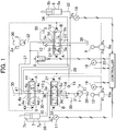
- the arm control valve 3 and the boom lower control valve 4 are disposed in order from an upstream side in series in a first main line 31 that supplies a hydraulic fluid delivered from the first hydraulic pump 1 to each of the actuators, i.e., the boom cylinder 6 and the arm cylinder 7.
- the boom upper control valve 5 is disposed in a second main line 32 that supplies a hydraulic fluid delivered from the second hydraulic pump 2 to the boom cylinder 6.
- the arm control valve 3 which is a 3-position, 6-port switching control valve, switches a control valve position in response to pilot pressures supplied to two pilot operation unit 3X and 3Y thereof to vary an opening area of a hydraulic fluid flow passage.
- the arm control valve 3 thereby controls a direction and a flow rate of the hydraulic fluid supplied from the first hydraulic pump 1 to the arm cylinder 7 to drive the arm cylinder 7.
- the arm control valve 3 includes an inlet port 3c to which the hydraulic fluid is supplied from the first hydraulic pump 1, an outlet port 3d that communicates with the hydraulic fluid tank 30, a center port 3T that communicates with the hydraulic fluid tank 3 when being at a neutral position, and connection ports 3a and 3b that are connected to the arm cylinder 7 side.
- the boom upper control valve 5 includes an inlet port 5c to which the hydraulic fluid is supplied from the second hydraulic pump 2, an outlet port 5d that communicates with the hydraulic fluid tank 30, a connection port 5e that communicates with a communication line 37 to be described later, a center port 5T that communicate with the hydraulic fluid tank 30 when being at a neutral position, and connection ports 5a and 5b that are connected to the boom cylinder 6 side.
- the boom upper control valve 5 is a center bypass type valve that leads the hydraulic fluid from the second hydraulic pump 2 to the hydraulic fluid tank 30 when being at a neutral position.
- a check valve 12 that allows the hydraulic fluid to flow only from the second hydraulic pump 2 is provided in a line that connects the second main line 32 to the inlet port 5c.
- a throttle is provided in an internal hydraulic line that communicates with the connection port 5a to the connection port 5e when the boom upper control valve 5 is at the position A.
- the boom lower control valve 4 includes an inlet port 4c to which the hydraulic fluid is supplied from the first hydraulic pump 1, an outlet port 4d that communicates with the hydraulic fluid tank 30, a connection port 4e that communicates with the communication line 37 to be described later, a center port 4T that communicate with the hydraulic fluid tank 30 when being at a neutral position, and connection ports 4a and 4b that are connected to the boom cylinder 6 side.
- the boom lower control valve 4 is a center bypass type valve that leads the hydraulic fluid from the first hydraulic pump 1 to the hydraulic fluid tank 30 when being at a neutral position. It is noted that a check valve 13 that allows the hydraulic fluid to flow only from the first hydraulic pump 1 is provided in a line that connects the first main line 31 to the inlet port 4c.
- the boom operation device 9 includes an operation lever and a pilot valve 9a, and generates a pilot pressure in response to an operation amount of a tilting operation of the operation lever. Pilot lines indicated by a broken line extend from the boom operation device 9 and are connected to the operation units 4X, 4Y, 5X, and 5Y of the boom lower control valve 4 and the boom upper control valve 5.
- a generated boom-raising pilot pressure Pu is supplied to the operation unit 4X of the boom lower control valve 4 and the operation unit 5X of the boom upper control valve 5, and the boom lower control valve 4 and the boom upper control valve 5 each performs a switching control in response to this pilot pressure.
- Fig. 1 when the operation lever of the boom operation device 9 is operated to perform the boom lowering operation, the boom-lowering pilot pressure Pd generated from the pilot valve 9a is supplied to the operation unit 4Y of the boom lower control valve 4 and the operation unit 5Y of the boom upper control valve 5.
- the boom lower control valve 4 moves in the left direction
- the boom upper control valve 5 moves in the right direction
- the valves 4 and 5 switch to the positions A.
- the hydraulic fluid from the first hydraulic pump 1 passes through from the inlet port 4c to the connection port 4b of the boom lower control valve 4 and is supplied to the rod-side hydraulic chamber 6b of the boom cylinder 6 via the second line 34.
- the hydraulic fluid from the second hydraulic pump 2 passes through from the inlet port 5c to the connection port 5b of the boom upper control valve 5 and is supplied to the rod-side hydraulic chamber 6b of the boom cylinder 6 via the second line 34.
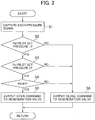
- FIG. 2 is a flowchart illustrating the processing by the controller that constitutes the first embodiment of the hydraulic fluid energy regeneration system for the work machine according to the present invention.
- the controller starts the process when, for example, the operator turns a key switch (not shown) of the hydraulic excavator to the ON position.
- the controller 20 captures the pressure signals (the boom cylinder bottom-side hydraulic chamber pressure Pb, the arm cylinder rod-side hydraulic chamber pressure Pr, the boom-lowering pilot pressure Pd, and the arm-dumping pilot pressure Po) detected by the respective pressure sensors 16 to 19 (Step S1).
- Step S2 judges whether the detected boom-lowering pilot pressure Pd is higher than a preset pilot set pressure 1 (Step S2). Specifically, the controller 20 judges whether the operation amount of the boom operation device 9 is equal to or larger than a predetermined operation amount. If the boom-lowering pilot pressure Pd is higher than the pilot set pressure 1 (the operation amount is equal to or larger than the predetermined operation amount), the controller 20 proceeds to Step S3; otherwise, the controller 20 proceeds to Step S6.
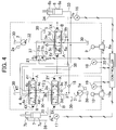
- FIG. 4 is a schematic diagram of a control system showing the second embodiment of the hydraulic fluid energy regeneration system for the work machine according to the present invention.
- the regeneration system is generally the same as the first embodiment but differs from the first embodiment in that the regeneration valve 8 is replaced by a solenoid selector valve 21.
- the selector valve 21 that is a 3-port, 2-position solenoid selector valve is provided in the communication line 37.
- the other end side of the communication line 37, the one end side of which is connected to the boom upper control valve 5, is connected to an inlet port of the selector valve 21, and the other end side of the communication line 37, the one end side of which is connected to the boom lower control valve 4, is connected to a first outlet port of the selector valve 21.
- One end side of the regeneration line 38 is connected to a second outlet port of the selector valve 21, and the other end side of the regeneration line 38 is connected to the first main line 31 via the check valve 15 that allows the hydraulic fluid to flow only from the regeneration line 38.
- the return hydraulic fluid discharged from the bottom-side hydraulic chamber 6a of the boom cylinder 6 flows into the communication line 37 and flows into both the boom lower control valve 4 and the regeneration line 38. Accordingly, if a regeneration flow rate is excessively high, then the flow rate of the return hydraulic fluid discharged from the boom cylinder 6 increases, and the falling speed of the piston rod of the boom cylinder 6 may become excessively high.
- variable throttles 21a and 21b in the two respective internal hydraulic lines of the selector valve 21 can reduce switching shock and suppress the rapid change in the speed of the piston rod of the boom cylinder 6. As a result, it is possible to improve operability and the safety.
Landscapes
- Engineering & Computer Science (AREA)
- General Engineering & Computer Science (AREA)
- Mining & Mineral Resources (AREA)
- Civil Engineering (AREA)
- Structural Engineering (AREA)
- Physics & Mathematics (AREA)
- Fluid Mechanics (AREA)
- Mechanical Engineering (AREA)
- Chemical & Material Sciences (AREA)
- Analytical Chemistry (AREA)
- Fluid-Pressure Circuits (AREA)
- Operation Control Of Excavators (AREA)
Applications Claiming Priority (2)
| Application Number | Priority Date | Filing Date | Title |
|---|---|---|---|
| JP2015112533A JP6453711B2 (ja) | 2015-06-02 | 2015-06-02 | 作業機械の圧油エネルギ再生装置 |
| PCT/JP2016/055305 WO2016194415A1 (ja) | 2015-06-02 | 2016-02-23 | 作業機械の圧油エネルギ再生装置 |
Publications (3)
| Publication Number | Publication Date |
|---|---|
| EP3306114A1 EP3306114A1 (en) | 2018-04-11 |
| EP3306114A4 EP3306114A4 (en) | 2019-01-16 |
| EP3306114B1 true EP3306114B1 (en) | 2021-01-20 |
Family
ID=57440837
Family Applications (1)
| Application Number | Title | Priority Date | Filing Date |
|---|---|---|---|
| EP16802854.6A Active EP3306114B1 (en) | 2015-06-02 | 2016-02-23 | Hydraulic energy regeneration system for work machine |
Country Status (6)
| Country | Link |
|---|---|
| US (1) | US10280594B2 (enExample) |
| EP (1) | EP3306114B1 (enExample) |
| JP (1) | JP6453711B2 (enExample) |
| KR (1) | KR101953049B1 (enExample) |
| CN (1) | CN107208675B (enExample) |
| WO (1) | WO2016194415A1 (enExample) |
Families Citing this family (12)
| Publication number | Priority date | Publication date | Assignee | Title |
|---|---|---|---|---|
| JP6879632B2 (ja) * | 2017-07-18 | 2021-06-02 | キャタピラー エス エー アール エル | 作業機械の制御装置 |
| JP6914206B2 (ja) * | 2018-01-11 | 2021-08-04 | 株式会社小松製作所 | 油圧回路 |
| JP6768106B2 (ja) * | 2019-03-22 | 2020-10-14 | Kyb株式会社 | 流体圧制御装置 |
| JP7342456B2 (ja) | 2019-06-28 | 2023-09-12 | コベルコ建機株式会社 | 油圧制御装置 |
| JP7268504B2 (ja) * | 2019-06-28 | 2023-05-08 | コベルコ建機株式会社 | 油圧制御装置 |
| CN110409527A (zh) * | 2019-06-28 | 2019-11-05 | 三一重机有限公司 | 一种动臂势能回收利用系统及挖掘机 |
| CN110359516A (zh) * | 2019-07-24 | 2019-10-22 | 青岛雷沃工程机械有限公司 | 挖掘机动臂下降液压控制系统及挖掘机 |
| JP2021038787A (ja) * | 2019-09-03 | 2021-03-11 | 川崎重工業株式会社 | 建設機械の油圧システム |
| CN115190929B (zh) * | 2020-06-17 | 2024-03-29 | 日立建机株式会社 | 工程机械 |
| JP7053731B2 (ja) * | 2020-07-15 | 2022-04-12 | 日立建機株式会社 | 作業機械 |
| JP7530312B2 (ja) * | 2021-02-12 | 2024-08-07 | 川崎重工業株式会社 | マルチ制御弁 |
| CN113914408B (zh) * | 2021-09-27 | 2023-02-28 | 徐工集团工程机械股份有限公司科技分公司 | 一种基于同轴流量放大的装载机定变量液压系统 |
Family Cites Families (14)
| Publication number | Priority date | Publication date | Assignee | Title |
|---|---|---|---|---|
| JPH0452481Y2 (enExample) * | 1986-07-31 | 1992-12-10 | ||
| JPH0323197A (ja) * | 1989-06-16 | 1991-01-31 | Toyota Autom Loom Works Ltd | バッテリ式産業車両における油圧装置 |
| US5442912A (en) * | 1992-12-04 | 1995-08-22 | Hitachi Construction Machinery Co., Ltd. | Hydraulic recovery device |
| JPH08219121A (ja) * | 1995-02-15 | 1996-08-27 | Hitachi Constr Mach Co Ltd | 油圧再生装置 |
| JP2001253649A (ja) * | 2000-03-15 | 2001-09-18 | Oil Drive Kogyo Kk | 油圧エレベータの油圧回路 |
| JP4209705B2 (ja) * | 2003-03-17 | 2009-01-14 | 日立建機株式会社 | 作業機の油圧回路 |
| JP4232974B2 (ja) * | 2004-06-24 | 2009-03-04 | キャタピラージャパン株式会社 | 建設機械の油圧制御回路 |
| JP2008014468A (ja) * | 2006-07-10 | 2008-01-24 | Shin Caterpillar Mitsubishi Ltd | 作業機械における油圧制御システム |
| JP4973047B2 (ja) | 2006-07-20 | 2012-07-11 | コベルコ建機株式会社 | 作業機械の油圧制御回路 |
| JP4867614B2 (ja) * | 2006-11-24 | 2012-02-01 | コベルコ建機株式会社 | 制御装置及びこれを備えた作業機械 |
| CN102947599B (zh) * | 2010-06-22 | 2015-03-11 | 日立建机株式会社 | 作业车辆的液压控制装置 |
| JP5785846B2 (ja) | 2011-10-17 | 2015-09-30 | 株式会社神戸製鋼所 | 油圧制御装置及びこれを備えた作業機械 |
| JP5928065B2 (ja) * | 2012-03-27 | 2016-06-01 | コベルコ建機株式会社 | 制御装置及びこれを備えた建設機械 |
| JP6291394B2 (ja) * | 2014-10-02 | 2018-03-14 | 日立建機株式会社 | 作業機械の油圧駆動システム |
-
2015
- 2015-06-02 JP JP2015112533A patent/JP6453711B2/ja active Active
-
2016
- 2016-02-23 CN CN201680008347.8A patent/CN107208675B/zh active Active
- 2016-02-23 US US15/554,601 patent/US10280594B2/en active Active
- 2016-02-23 EP EP16802854.6A patent/EP3306114B1/en active Active
- 2016-02-23 KR KR1020177021705A patent/KR101953049B1/ko active Active
- 2016-02-23 WO PCT/JP2016/055305 patent/WO2016194415A1/ja not_active Ceased
Non-Patent Citations (1)
| Title |
|---|
| None * |
Also Published As
| Publication number | Publication date |
|---|---|
| JP6453711B2 (ja) | 2019-01-16 |
| EP3306114A1 (en) | 2018-04-11 |
| EP3306114A4 (en) | 2019-01-16 |
| KR20170101992A (ko) | 2017-09-06 |
| JP2016223590A (ja) | 2016-12-28 |
| US20180044890A1 (en) | 2018-02-15 |
| CN107208675A (zh) | 2017-09-26 |
| US10280594B2 (en) | 2019-05-07 |
| WO2016194415A1 (ja) | 2016-12-08 |
| KR101953049B1 (ko) | 2019-02-27 |
| CN107208675B (zh) | 2018-11-02 |
Similar Documents
| Publication | Publication Date | Title |
|---|---|---|
| EP3306114B1 (en) | Hydraulic energy regeneration system for work machine | |
| KR101890263B1 (ko) | 건설 기계 | |
| US8499552B2 (en) | Method and hydraulic control system for supplying pressure medium to at least one hydraulic consumer | |
| US10526767B2 (en) | Construction machine | |
| US8671824B2 (en) | Hydraulic control system | |
| US10677274B2 (en) | Hydraulic excavator drive system | |
| JP5661084B2 (ja) | 作業機械の油圧駆動装置 | |
| US7353744B2 (en) | Hydraulic control | |
| JP2016223590A5 (enExample) | ||
| US20180291935A1 (en) | Hydraulic drive system of construction machine | |
| JP2017226492A (ja) | 液圧駆動システム | |
| CN114270055B (zh) | 建筑机械的油压系统 | |
| JP2017226492A5 (enExample) | ||
| CN108105182A (zh) | 油压驱动系统 | |
| KR102357613B1 (ko) | 쇼벨, 쇼벨용 컨트롤밸브 | |
| CN107217694B (zh) | 挖土机 | |
| CN105971043B (zh) | 挖土机 | |
| CN111356844B (zh) | 油压驱动系统 | |
| CN108884843B (zh) | 挖土机及挖土机用控制阀门 | |
| JP2015137474A (ja) | 作業車両 | |
| US11459729B2 (en) | Hydraulic excavator drive system | |
| WO2018193741A1 (ja) | 流体圧制御装置およびこれを備えるフォークリフト | |
| JP2011236971A (ja) | 作業機械の油圧システム | |
| WO2018193740A1 (ja) | 流体圧制御装置およびこれを備えるフォークリフト |
Legal Events
| Date | Code | Title | Description |
|---|---|---|---|
| STAA | Information on the status of an ep patent application or granted ep patent |
Free format text: STATUS: THE INTERNATIONAL PUBLICATION HAS BEEN MADE |
|
| PUAI | Public reference made under article 153(3) epc to a published international application that has entered the european phase |
Free format text: ORIGINAL CODE: 0009012 |
|
| STAA | Information on the status of an ep patent application or granted ep patent |
Free format text: STATUS: REQUEST FOR EXAMINATION WAS MADE |
|
| 17P | Request for examination filed |
Effective date: 20180102 |
|
| AK | Designated contracting states |
Kind code of ref document: A1 Designated state(s): AL AT BE BG CH CY CZ DE DK EE ES FI FR GB GR HR HU IE IS IT LI LT LU LV MC MK MT NL NO PL PT RO RS SE SI SK SM TR |
|
| AX | Request for extension of the european patent |
Extension state: BA ME |
|
| DAV | Request for validation of the european patent (deleted) | ||
| DAX | Request for extension of the european patent (deleted) | ||
| REG | Reference to a national code |
Ref country code: DE Ref legal event code: R079 Ref document number: 602016051758 Country of ref document: DE Free format text: PREVIOUS MAIN CLASS: F15B0021140000 Ipc: E02F0009220000 |
|
| A4 | Supplementary search report drawn up and despatched |
Effective date: 20181217 |
|
| RIC1 | Information provided on ipc code assigned before grant |
Ipc: E02F 9/22 20060101AFI20181211BHEP Ipc: F15B 21/14 20060101ALI20181211BHEP Ipc: F15B 20/00 20060101ALI20181211BHEP Ipc: F15B 11/16 20060101ALI20181211BHEP Ipc: F15B 11/00 20060101ALI20181211BHEP Ipc: F15B 11/08 20060101ALI20181211BHEP |
|
| GRAP | Despatch of communication of intention to grant a patent |
Free format text: ORIGINAL CODE: EPIDOSNIGR1 |
|
| STAA | Information on the status of an ep patent application or granted ep patent |
Free format text: STATUS: GRANT OF PATENT IS INTENDED |
|
| INTG | Intention to grant announced |
Effective date: 20201029 |
|
| GRAS | Grant fee paid |
Free format text: ORIGINAL CODE: EPIDOSNIGR3 |
|
| GRAA | (expected) grant |
Free format text: ORIGINAL CODE: 0009210 |
|
| STAA | Information on the status of an ep patent application or granted ep patent |
Free format text: STATUS: THE PATENT HAS BEEN GRANTED |
|
| AK | Designated contracting states |
Kind code of ref document: B1 Designated state(s): AL AT BE BG CH CY CZ DE DK EE ES FI FR GB GR HR HU IE IS IT LI LT LU LV MC MK MT NL NO PL PT RO RS SE SI SK SM TR |
|
| REG | Reference to a national code |
Ref country code: GB Ref legal event code: FG4D |
|
| REG | Reference to a national code |
Ref country code: CH Ref legal event code: EP |
|
| REG | Reference to a national code |
Ref country code: DE Ref legal event code: R096 Ref document number: 602016051758 Country of ref document: DE |
|
| REG | Reference to a national code |
Ref country code: AT Ref legal event code: REF Ref document number: 1356516 Country of ref document: AT Kind code of ref document: T Effective date: 20210215 |
|
| REG | Reference to a national code |
Ref country code: IE Ref legal event code: FG4D |
|
| REG | Reference to a national code |
Ref country code: NL Ref legal event code: MP Effective date: 20210120 |
|
| REG | Reference to a national code |
Ref country code: LT Ref legal event code: MG9D |
|
| REG | Reference to a national code |
Ref country code: AT Ref legal event code: MK05 Ref document number: 1356516 Country of ref document: AT Kind code of ref document: T Effective date: 20210120 |
|
| PG25 | Lapsed in a contracting state [announced via postgrant information from national office to epo] |
Ref country code: LT Free format text: LAPSE BECAUSE OF FAILURE TO SUBMIT A TRANSLATION OF THE DESCRIPTION OR TO PAY THE FEE WITHIN THE PRESCRIBED TIME-LIMIT Effective date: 20210120 Ref country code: BG Free format text: LAPSE BECAUSE OF FAILURE TO SUBMIT A TRANSLATION OF THE DESCRIPTION OR TO PAY THE FEE WITHIN THE PRESCRIBED TIME-LIMIT Effective date: 20210420 Ref country code: PT Free format text: LAPSE BECAUSE OF FAILURE TO SUBMIT A TRANSLATION OF THE DESCRIPTION OR TO PAY THE FEE WITHIN THE PRESCRIBED TIME-LIMIT Effective date: 20210520 Ref country code: NO Free format text: LAPSE BECAUSE OF FAILURE TO SUBMIT A TRANSLATION OF THE DESCRIPTION OR TO PAY THE FEE WITHIN THE PRESCRIBED TIME-LIMIT Effective date: 20210420 Ref country code: GR Free format text: LAPSE BECAUSE OF FAILURE TO SUBMIT A TRANSLATION OF THE DESCRIPTION OR TO PAY THE FEE WITHIN THE PRESCRIBED TIME-LIMIT Effective date: 20210421 Ref country code: HR Free format text: LAPSE BECAUSE OF FAILURE TO SUBMIT A TRANSLATION OF THE DESCRIPTION OR TO PAY THE FEE WITHIN THE PRESCRIBED TIME-LIMIT Effective date: 20210120 Ref country code: FI Free format text: LAPSE BECAUSE OF FAILURE TO SUBMIT A TRANSLATION OF THE DESCRIPTION OR TO PAY THE FEE WITHIN THE PRESCRIBED TIME-LIMIT Effective date: 20210120 |
|
| PG25 | Lapsed in a contracting state [announced via postgrant information from national office to epo] |
Ref country code: SE Free format text: LAPSE BECAUSE OF FAILURE TO SUBMIT A TRANSLATION OF THE DESCRIPTION OR TO PAY THE FEE WITHIN THE PRESCRIBED TIME-LIMIT Effective date: 20210120 Ref country code: LV Free format text: LAPSE BECAUSE OF FAILURE TO SUBMIT A TRANSLATION OF THE DESCRIPTION OR TO PAY THE FEE WITHIN THE PRESCRIBED TIME-LIMIT Effective date: 20210120 Ref country code: PL Free format text: LAPSE BECAUSE OF FAILURE TO SUBMIT A TRANSLATION OF THE DESCRIPTION OR TO PAY THE FEE WITHIN THE PRESCRIBED TIME-LIMIT Effective date: 20210120 Ref country code: RS Free format text: LAPSE BECAUSE OF FAILURE TO SUBMIT A TRANSLATION OF THE DESCRIPTION OR TO PAY THE FEE WITHIN THE PRESCRIBED TIME-LIMIT Effective date: 20210120 Ref country code: AT Free format text: LAPSE BECAUSE OF FAILURE TO SUBMIT A TRANSLATION OF THE DESCRIPTION OR TO PAY THE FEE WITHIN THE PRESCRIBED TIME-LIMIT Effective date: 20210120 |
|
| PG25 | Lapsed in a contracting state [announced via postgrant information from national office to epo] |
Ref country code: IS Free format text: LAPSE BECAUSE OF FAILURE TO SUBMIT A TRANSLATION OF THE DESCRIPTION OR TO PAY THE FEE WITHIN THE PRESCRIBED TIME-LIMIT Effective date: 20210520 |
|
| REG | Reference to a national code |
Ref country code: DE Ref legal event code: R097 Ref document number: 602016051758 Country of ref document: DE |
|
| REG | Reference to a national code |
Ref country code: BE Ref legal event code: MM Effective date: 20210228 |
|
| PG25 | Lapsed in a contracting state [announced via postgrant information from national office to epo] |
Ref country code: SM Free format text: LAPSE BECAUSE OF FAILURE TO SUBMIT A TRANSLATION OF THE DESCRIPTION OR TO PAY THE FEE WITHIN THE PRESCRIBED TIME-LIMIT Effective date: 20210120 Ref country code: CH Free format text: LAPSE BECAUSE OF NON-PAYMENT OF DUE FEES Effective date: 20210228 Ref country code: EE Free format text: LAPSE BECAUSE OF FAILURE TO SUBMIT A TRANSLATION OF THE DESCRIPTION OR TO PAY THE FEE WITHIN THE PRESCRIBED TIME-LIMIT Effective date: 20210120 Ref country code: CZ Free format text: LAPSE BECAUSE OF FAILURE TO SUBMIT A TRANSLATION OF THE DESCRIPTION OR TO PAY THE FEE WITHIN THE PRESCRIBED TIME-LIMIT Effective date: 20210120 Ref country code: LI Free format text: LAPSE BECAUSE OF NON-PAYMENT OF DUE FEES Effective date: 20210228 Ref country code: LU Free format text: LAPSE BECAUSE OF NON-PAYMENT OF DUE FEES Effective date: 20210223 Ref country code: MC Free format text: LAPSE BECAUSE OF FAILURE TO SUBMIT A TRANSLATION OF THE DESCRIPTION OR TO PAY THE FEE WITHIN THE PRESCRIBED TIME-LIMIT Effective date: 20210120 |
|
| PLBE | No opposition filed within time limit |
Free format text: ORIGINAL CODE: 0009261 |
|
| STAA | Information on the status of an ep patent application or granted ep patent |
Free format text: STATUS: NO OPPOSITION FILED WITHIN TIME LIMIT |
|
| PG25 | Lapsed in a contracting state [announced via postgrant information from national office to epo] |
Ref country code: DK Free format text: LAPSE BECAUSE OF FAILURE TO SUBMIT A TRANSLATION OF THE DESCRIPTION OR TO PAY THE FEE WITHIN THE PRESCRIBED TIME-LIMIT Effective date: 20210120 Ref country code: RO Free format text: LAPSE BECAUSE OF FAILURE TO SUBMIT A TRANSLATION OF THE DESCRIPTION OR TO PAY THE FEE WITHIN THE PRESCRIBED TIME-LIMIT Effective date: 20210120 Ref country code: SK Free format text: LAPSE BECAUSE OF FAILURE TO SUBMIT A TRANSLATION OF THE DESCRIPTION OR TO PAY THE FEE WITHIN THE PRESCRIBED TIME-LIMIT Effective date: 20210120 |
|
| 26N | No opposition filed |
Effective date: 20211021 |
|
| PG25 | Lapsed in a contracting state [announced via postgrant information from national office to epo] |
Ref country code: AL Free format text: LAPSE BECAUSE OF FAILURE TO SUBMIT A TRANSLATION OF THE DESCRIPTION OR TO PAY THE FEE WITHIN THE PRESCRIBED TIME-LIMIT Effective date: 20210120 Ref country code: ES Free format text: LAPSE BECAUSE OF FAILURE TO SUBMIT A TRANSLATION OF THE DESCRIPTION OR TO PAY THE FEE WITHIN THE PRESCRIBED TIME-LIMIT Effective date: 20210120 Ref country code: FR Free format text: LAPSE BECAUSE OF NON-PAYMENT OF DUE FEES Effective date: 20210320 Ref country code: IE Free format text: LAPSE BECAUSE OF NON-PAYMENT OF DUE FEES Effective date: 20210223 |
|
| PG25 | Lapsed in a contracting state [announced via postgrant information from national office to epo] |
Ref country code: SI Free format text: LAPSE BECAUSE OF FAILURE TO SUBMIT A TRANSLATION OF THE DESCRIPTION OR TO PAY THE FEE WITHIN THE PRESCRIBED TIME-LIMIT Effective date: 20210120 |
|
| PG25 | Lapsed in a contracting state [announced via postgrant information from national office to epo] |
Ref country code: IT Free format text: LAPSE BECAUSE OF FAILURE TO SUBMIT A TRANSLATION OF THE DESCRIPTION OR TO PAY THE FEE WITHIN THE PRESCRIBED TIME-LIMIT Effective date: 20210120 |
|
| PG25 | Lapsed in a contracting state [announced via postgrant information from national office to epo] |
Ref country code: IS Free format text: LAPSE BECAUSE OF FAILURE TO SUBMIT A TRANSLATION OF THE DESCRIPTION OR TO PAY THE FEE WITHIN THE PRESCRIBED TIME-LIMIT Effective date: 20210520 |
|
| PG25 | Lapsed in a contracting state [announced via postgrant information from national office to epo] |
Ref country code: BE Free format text: LAPSE BECAUSE OF NON-PAYMENT OF DUE FEES Effective date: 20210228 |
|
| PG25 | Lapsed in a contracting state [announced via postgrant information from national office to epo] |
Ref country code: NL Free format text: LAPSE BECAUSE OF NON-PAYMENT OF DUE FEES Effective date: 20210120 Ref country code: CY Free format text: LAPSE BECAUSE OF FAILURE TO SUBMIT A TRANSLATION OF THE DESCRIPTION OR TO PAY THE FEE WITHIN THE PRESCRIBED TIME-LIMIT Effective date: 20210120 |
|
| PG25 | Lapsed in a contracting state [announced via postgrant information from national office to epo] |
Ref country code: HU Free format text: LAPSE BECAUSE OF FAILURE TO SUBMIT A TRANSLATION OF THE DESCRIPTION OR TO PAY THE FEE WITHIN THE PRESCRIBED TIME-LIMIT; INVALID AB INITIO Effective date: 20160223 |
|
| PG25 | Lapsed in a contracting state [announced via postgrant information from national office to epo] |
Ref country code: MK Free format text: LAPSE BECAUSE OF FAILURE TO SUBMIT A TRANSLATION OF THE DESCRIPTION OR TO PAY THE FEE WITHIN THE PRESCRIBED TIME-LIMIT Effective date: 20210120 |
|
| PG25 | Lapsed in a contracting state [announced via postgrant information from national office to epo] |
Ref country code: MT Free format text: LAPSE BECAUSE OF FAILURE TO SUBMIT A TRANSLATION OF THE DESCRIPTION OR TO PAY THE FEE WITHIN THE PRESCRIBED TIME-LIMIT Effective date: 20210120 |
|
| PGFP | Annual fee paid to national office [announced via postgrant information from national office to epo] |
Ref country code: DE Payment date: 20241231 Year of fee payment: 10 |
|
| PGFP | Annual fee paid to national office [announced via postgrant information from national office to epo] |
Ref country code: GB Payment date: 20250102 Year of fee payment: 10 |