EP3302338B1 - Marker materials and forms for magnetic marker localization - Google Patents
Marker materials and forms for magnetic marker localization Download PDFInfo
- Publication number
- EP3302338B1 EP3302338B1 EP16728722.6A EP16728722A EP3302338B1 EP 3302338 B1 EP3302338 B1 EP 3302338B1 EP 16728722 A EP16728722 A EP 16728722A EP 3302338 B1 EP3302338 B1 EP 3302338B1
- Authority
- EP
- European Patent Office
- Prior art keywords
- magnetic
- marker
- anisotropy
- deployment
- susceptibility
- Prior art date
- Legal status (The legal status is an assumption and is not a legal conclusion. Google has not performed a legal analysis and makes no representation as to the accuracy of the status listed.)
- Active
Links
Images


Classifications
-
- A—HUMAN NECESSITIES
- A61—MEDICAL OR VETERINARY SCIENCE; HYGIENE
- A61B—DIAGNOSIS; SURGERY; IDENTIFICATION
- A61B90/00—Instruments, implements or accessories specially adapted for surgery or diagnosis and not covered by any of the groups A61B1/00 - A61B50/00, e.g. for luxation treatment or for protecting wound edges
- A61B90/39—Markers, e.g. radio-opaque or breast lesions markers
-
- A—HUMAN NECESSITIES
- A61—MEDICAL OR VETERINARY SCIENCE; HYGIENE
- A61B—DIAGNOSIS; SURGERY; IDENTIFICATION
- A61B5/00—Measuring for diagnostic purposes; Identification of persons
- A61B5/05—Detecting, measuring or recording for diagnosis by means of electric currents or magnetic fields; Measuring using microwaves or radio waves
-
- A—HUMAN NECESSITIES
- A61—MEDICAL OR VETERINARY SCIENCE; HYGIENE
- A61B—DIAGNOSIS; SURGERY; IDENTIFICATION
- A61B5/00—Measuring for diagnostic purposes; Identification of persons
- A61B5/43—Detecting, measuring or recording for evaluating the reproductive systems
- A61B5/4306—Detecting, measuring or recording for evaluating the reproductive systems for evaluating the female reproductive systems, e.g. gynaecological evaluations
- A61B5/4312—Breast evaluation or disorder diagnosis
-
- H—ELECTRICITY
- H01—ELECTRIC ELEMENTS
- H01F—MAGNETS; INDUCTANCES; TRANSFORMERS; SELECTION OF MATERIALS FOR THEIR MAGNETIC PROPERTIES
- H01F1/00—Magnets or magnetic bodies characterised by the magnetic materials therefor; Selection of materials for their magnetic properties
- H01F1/01—Magnets or magnetic bodies characterised by the magnetic materials therefor; Selection of materials for their magnetic properties of inorganic materials
- H01F1/03—Magnets or magnetic bodies characterised by the magnetic materials therefor; Selection of materials for their magnetic properties of inorganic materials characterised by their coercivity
- H01F1/032—Magnets or magnetic bodies characterised by the magnetic materials therefor; Selection of materials for their magnetic properties of inorganic materials characterised by their coercivity of hard-magnetic materials
-
- H—ELECTRICITY
- H01—ELECTRIC ELEMENTS
- H01F—MAGNETS; INDUCTANCES; TRANSFORMERS; SELECTION OF MATERIALS FOR THEIR MAGNETIC PROPERTIES
- H01F1/00—Magnets or magnetic bodies characterised by the magnetic materials therefor; Selection of materials for their magnetic properties
- H01F1/01—Magnets or magnetic bodies characterised by the magnetic materials therefor; Selection of materials for their magnetic properties of inorganic materials
- H01F1/03—Magnets or magnetic bodies characterised by the magnetic materials therefor; Selection of materials for their magnetic properties of inorganic materials characterised by their coercivity
- H01F1/12—Magnets or magnetic bodies characterised by the magnetic materials therefor; Selection of materials for their magnetic properties of inorganic materials characterised by their coercivity of soft-magnetic materials
-
- A—HUMAN NECESSITIES
- A61—MEDICAL OR VETERINARY SCIENCE; HYGIENE
- A61B—DIAGNOSIS; SURGERY; IDENTIFICATION
- A61B17/00—Surgical instruments, devices or methods
- A61B2017/00831—Material properties
- A61B2017/00862—Material properties elastic or resilient
-
- A—HUMAN NECESSITIES
- A61—MEDICAL OR VETERINARY SCIENCE; HYGIENE
- A61B—DIAGNOSIS; SURGERY; IDENTIFICATION
- A61B90/00—Instruments, implements or accessories specially adapted for surgery or diagnosis and not covered by any of the groups A61B1/00 - A61B50/00, e.g. for luxation treatment or for protecting wound edges
- A61B90/39—Markers, e.g. radio-opaque or breast lesions markers
- A61B2090/3904—Markers, e.g. radio-opaque or breast lesions markers specially adapted for marking specified tissue
- A61B2090/3908—Soft tissue, e.g. breast tissue
-
- A—HUMAN NECESSITIES
- A61—MEDICAL OR VETERINARY SCIENCE; HYGIENE
- A61B—DIAGNOSIS; SURGERY; IDENTIFICATION
- A61B90/00—Instruments, implements or accessories specially adapted for surgery or diagnosis and not covered by any of the groups A61B1/00 - A61B50/00, e.g. for luxation treatment or for protecting wound edges
- A61B90/39—Markers, e.g. radio-opaque or breast lesions markers
- A61B2090/3925—Markers, e.g. radio-opaque or breast lesions markers ultrasonic
-
- A—HUMAN NECESSITIES
- A61—MEDICAL OR VETERINARY SCIENCE; HYGIENE
- A61B—DIAGNOSIS; SURGERY; IDENTIFICATION
- A61B90/00—Instruments, implements or accessories specially adapted for surgery or diagnosis and not covered by any of the groups A61B1/00 - A61B50/00, e.g. for luxation treatment or for protecting wound edges
- A61B90/39—Markers, e.g. radio-opaque or breast lesions markers
- A61B2090/3954—Markers, e.g. radio-opaque or breast lesions markers magnetic, e.g. NMR or MRI
-
- A—HUMAN NECESSITIES
- A61—MEDICAL OR VETERINARY SCIENCE; HYGIENE
- A61B—DIAGNOSIS; SURGERY; IDENTIFICATION
- A61B90/00—Instruments, implements or accessories specially adapted for surgery or diagnosis and not covered by any of the groups A61B1/00 - A61B50/00, e.g. for luxation treatment or for protecting wound edges
- A61B90/39—Markers, e.g. radio-opaque or breast lesions markers
- A61B2090/3966—Radiopaque markers visible in an X-ray image
-
- A—HUMAN NECESSITIES
- A61—MEDICAL OR VETERINARY SCIENCE; HYGIENE
- A61B—DIAGNOSIS; SURGERY; IDENTIFICATION
- A61B90/00—Instruments, implements or accessories specially adapted for surgery or diagnosis and not covered by any of the groups A61B1/00 - A61B50/00, e.g. for luxation treatment or for protecting wound edges
- A61B90/39—Markers, e.g. radio-opaque or breast lesions markers
- A61B2090/3987—Applicators for implanting markers
-
- A—HUMAN NECESSITIES
- A61—MEDICAL OR VETERINARY SCIENCE; HYGIENE
- A61B—DIAGNOSIS; SURGERY; IDENTIFICATION
- A61B90/00—Instruments, implements or accessories specially adapted for surgery or diagnosis and not covered by any of the groups A61B1/00 - A61B50/00, e.g. for luxation treatment or for protecting wound edges
- A61B90/39—Markers, e.g. radio-opaque or breast lesions markers
- A61B2090/3995—Multi-modality markers
-
- A—HUMAN NECESSITIES
- A61—MEDICAL OR VETERINARY SCIENCE; HYGIENE
- A61B—DIAGNOSIS; SURGERY; IDENTIFICATION
- A61B2562/00—Details of sensors; Constructional details of sensor housings or probes; Accessories for sensors
- A61B2562/02—Details of sensors specially adapted for in-vivo measurements
- A61B2562/0223—Magnetic field sensors
Definitions
- the invention relates generally to the field of markers for medical detection and more specifically to magnetic medical markers.
- WGL wire-guided localization
- ROLL Radioguided Occult Lesion Localization
- Magnetic markers are also used, and they overcome the inconvenience and logistical challenges that arise by using a radioactive material as a marker, and they also avoid the drawbacks of guide-wires.
- magnetic markers are relatively complex to manufacture compared with guide-wires.
- All known marking devices are introduced through a hollow needle or cannula.
- this needle is typically narrow in diameter.
- the small diameter of the needle constrains the marker cross section.
- this dimension is generally 14 to 18 gauge.
- the needle has an internal diameter generally of 0.8mm to 1.5mm but may possibly be as large as 1.8mm for certain needle designs.
- the needle size is typically 11 gauge, with an internal diameter of 2.3 to 2.5 mm.
- the magnetic markers are typically constrained to be less than 1.5mm in diameter. In practice, these size constraints limit the magnetic response and in turn the ease with which the marker can be localised with a magnetic probe. Therefore, a stronger magnetic response is desired.
- Another challenge for magnetic biopsy markers is that to achieve an effective magnetic response, the volume of material needs to be maximised.
- This volume requirement results in a typically shaped marker having a length significantly greater than its diameter.
- Such markers are in the region of 1mm to 12mm, with a length to diameter ratio greater than 5.
- This aspect ratio results in a non-uniform magnetic response with a much stronger signal being obtained when the marker major axis is in line with a probe, and a weaker signal when the marker major axis is transverse to the probe. A more uniform response is generally desired.
- the marker is generally guided to its position and confirmed to be in place under ultrasound or stereotactic x-ray imaging. This means that it is desirable for the marker to be clearly visible under X-ray and ultrasound imaging, and preferably under MRI, which can also be used for this purpose.
- What is needed is a marker that has a small amount of material without reducing the intensity of the detectable signal, and provides a more uniform response from any direction relative to the magnetic probe.
- the present invention addresses this need.
- US 2008/097199 A1 discloses a marker for marking a site within the body of a mammalian patient positioned within the tissue of a patient.
- the marker may be placed in the first instance by a needle or the like or placed where a tissue sample has been removed.
- the marker has a plurality of loops each at various angles to the other such that when positioned within the patient, one of the loops is positioned orthogonal to a magnetic field of a metal detector.
- Normal delivery techniques as needles, catheters or cannulas may readily position the marker within the patient.
- the marker is compressed inside of the cannula and is positioned by the practitioner. Upon exiting the cannula, the marker expands and partially or fully decompresses. Upon decompression, the marker will display a plurality of loops, one or more of which will be positioned orthogonal to the metal detector field.
- US 2006/079805 A1 discloses an intracorporeal site marker that is adapted to be implanted into a biopsy cavity includes a plurality of balls or particles.
- the balls or particles are either sintered together or bonded together.
- Other alternative embodiments of site markers visible under various imaging modes are also disclosed.
- the invention relates to magnetic markers for surgical use.
- it relates to magnetic markers with a more uniform magnetic response once deployed than would be expected from their geometry prior to deployment.
- markers are provided whose shape is chosen such that they give a more uniform magnetic response.
- markers are provided whose geometrical configuration changes once deployed such that they give a more uniform magnetic response.
- markers are provided whose material composition is chosen such that they give a more uniform magnetic response than would be expected from their geometry prior to deployment.
- the marker is in a non-spherical configuration having a ratio of anisotropy of magnetic susceptibility of less than 5.
- the marker is in a non-spherical configuration having a ratio of anisotropy of magnetic susceptibility of less than 3.
- the non-spherical marker configuration is of the shape selected from the group comprising a cylinder, a cable, a "dumbbell-like" form, a bead and a ball of yarn.
- the cylinder bends upon placement in tissue.
- the non-spherical configuration is faceted.
- the marker is a magnetic marker for marking a site in tissue in the body comprising: a plurality of magnetic components linked by flexible non-magnetic components that compact upon placement in the site.
- the magnetic marker for marking a site in tissue in the body includes a magnetic component of a first shape located within a non-magnetic matrix of a second shape.
- the magnetic marker for marking a site in tissue in the body includes a magnetic material core within a magnetic material sheath.
- one of the core and the sheath is a soft-magnetic material.
- the magnetic marker for marking a site in tissue in the body includes a plurality of magnetic components which self assemble into the magnetic marker following placement of the markers into the body.
- the magnetic components are each encased within a super-hydrophobic coating.
- the magnetic marker for marking a site in tissue in the body includes a magnetic metallic glass.
- SPIO superparamagnetic iron oxide
- Another challenge for magnetic biopsy markers is that to achieve an effective magnetic response, the volume of material needs to be maximised. These requirements result in a typical marker having length significantly greater than the diameter because the marker must be delivered through a needle and smaller needle gauges (diameters) are less painful for patients. Such markers are in the region of 1mm to 12mm, with length to diameter ratio greater than 5. In practice, these size constraints limit the magnetic response and in turn the ease with which the marker can be localised with a magnetic probe. Therefore a stronger response is desired.
- the marker is generally guided to its position and confirmed to be in place under ultrasound or stereotactic x-ray imaging.
- SPIO particles have limited visibility under X-ray imaging but can be made ultrasound visible by combining them in a matrix of echogenic material, for example a polymer.
- magnetic markers overcome the drawbacks of guide-wires and radioactive approaches, there remains a need for a magnetic marker that can be introduced through a narrow needle, gives a strong magnetic response, is visible under X-ray and ultrasound imaging, and can be manufactured simply.
- Magnetic susceptibility can be measured by a range of known methods including the Faraday balance, Gouy balance, the magnetic resonance method, and the inductive method with SQUID magnetometer. Magnetic susceptibility can also be calculated using computer-based finite element magnetic modelling packages such as ANSYS Maxwell (ANSYS Inc., Canonsburg, PA), by modelling the marker in a homogenous field and measuring the distortions caused by the marker which correspond to the magnetic susceptibility. See for example the method described in: " Magnetic Susceptibility Modelling Using ANSYS", K. Bartusek et al., Progress In Electromagnetics Research Symposium Proceedings, Marrakesh, Morocco, Mar. 20-23,2011 .
- ANSYS Maxwell ANSYS Inc., Canonsburg, PA
- a magnetic mass susceptibility can be defined which is the induced magnetic response per unit mass of the material.
- Magnetic mass susceptibility, ⁇ ⁇ k/ ⁇ where ⁇ is the density of the material and ⁇ ⁇ has units of m 3 /kg. This is a normalized susceptibility and allows the relative susceptibilities of different materials to be compared.
- the magnetic mass susceptibility of 316 stainless steel has a range of approximately is approximately 3.80x10 -7 to 1.27x10 -6
- a permanent Neodymium magnet has a value approximately of 6.67x10 -6
- Super Paramagnetic Iron Oxide (SPIO) based markers have a value of approximately 2.5 x10 -5 - 1.0x10 -3 depending on the density of particles in a matrix
- NiZn-ferrites have a range of approximately 3x10 -3 to 1.22x10 -1 . Therefore, the NiZn-ferrites require less material to be detected than SPIO which in turn require less material than permanent Neodymium magnetic material or 316 stainless steel.
- H demag is the 'demagnetisation field'
- N x + N y + N z 1.
- the shape of that marker will affect the ease with which it may be localized.
- the induced field, H marker will therefore also be reduced by a factor of (1 + 1 ⁇ 3 ⁇ ) at any given r , but this reduction will be present irrespective of the orientation of the marker to the magnetizing field H.
- the measured ⁇ ratio of 10.3:1 for a cylinder of aspect ratio 7:1 corresponds to an N ⁇ of approximately 0.48; while the same material in a cylinder of aspect ratio 3.7:1 exhibited an anisotropy ratio ⁇ of approximately 4.7:1, corresponding to an N ⁇ of approximately 0.44.
- the magnetic response depends partly on the mass susceptibility of its constituent material or materials, and partly on the shape of the marker, and for a given shape, the response can change with orientation of the marker.
- the anisotropy of the magnetic response can be calculated by using demagnetization factors as outlined above. However, as demagnetization factors are very difficult to calculate for real shapes, a more practical approach is needed to define the anisotropy of the response.
- the change in magnetic response with orientation for a given marker can be thought of as a change in the 'effective susceptibility' of the marker.
- the underlying susceptibility of the marker material does not change, but the change in magnetic response due to the combination of material, shape and orientation can be defined as if the susceptibility were varying.
- a ratio can be defined of the maximum (effective) magnetic susceptibility to the minimum (effective) magnetic susceptibility. This ratio can be referred to as the anisotropy of the magnetic susceptibility and gives an indication of the uniformity of the magnetic susceptibility response along different axes of the marker or from different directions.
- Anisotropy of magnetic susceptibility Maximum magnetic susceptibility Minimum magnetic susceptibility
- the anisotropy of magnetic susceptibility is also dimensionless. If the anisotropy is 1, the susceptibility is the same from any direction. If the anisotropy is high, the susceptibility is very non-uniform with respect to the orientation of the marker.
- anisotropy of magnetic susceptibility is described in the art and can be measured by a number of methods.
- two types of directional susceptibility meter are described in A. K. Dubey, " Understanding an Orogenic Belt , " Springer Geology: An equal-impedance bridge where the specimen can be inserted into a coil; and a balanced-transformer system where the specimen is placed inside a ferrite ring.
- a further method called a three dimensional magnetic anisotropic susceptibility meter is described in US Patent No. 3,492,566 . In each case, a consistent magnetic field is applied to the sample, and the variation in the induced magnetic response is measured as the sample orientation is varied.
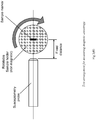
- FIG. 2(C) A further such method is shown in Figure 2(C) in which a susceptometry probe is used to measure the induced magnetic response.
- a susceptometry probe is used to measure the induced magnetic response.
- markers produced from various materials and in various forms had their maximum and minimum signals measured at a fixed distance. Results are shown in Table 3.
- Measuring the anisotropy of magnetic susceptibility using a magnetic susceptibility probe or meter is the ideal approach to defining the uniformity of the magnetic response of a marker.
- the projected area of the marker in any direction can be measured and maximum and minimum projected areas determined.
- a lower projected area indicates a greater focussing effect of the field and visa versa.
- the uniformity of response can thus be defined by the ratio of the minimum projected area to the maximum projected area of the marker out of all the available viewpoints or directions.
- this ratio of projected areas is approximately equal to the shape factor of the marker, which is defined as the ratio of the largest dimension of the marker to its smallest dimension and this too can be used as an approximation to the anisotropy of magnetic susceptibility. Both these geometric methods do not account for variations in the magnetic properties within the marker.
- the term 'anisotropy of magnetic susceptibility' or magnetic anisotropy is used throughout, the term 'projected area anisotropy' or 'ratio of largest to smallest dimension' are understood as alternative interchangeable measures of the uniformity of the magnetic response.
- the anisotropy of magnetic susceptibility can be determined for the marker both before deployment when in the delivery device and after deployment. Where the marker configuration changes, the anisotropy of magnetic susceptibility may have a different value before and after deployment.
- An anisotropy ratio of less than 7 i.e. between 1 and 7
- preferably less than 5 and more preferably less than 3 is desirable. Because the magnetic response reduces with distance exponentially, an anisotropy ratio of less than 2 is close enough to the ideal for practical use.
- an ideal magnetic marker becomes magnetized in the presence of a magnetic field and exhibits no permanent magnetic remanence (retained magnetisation) when the field is removed, or in other words, an ideal marker is magnetically soft, i.e. formed from magnetically soft material or behaving as if it is magnetically soft.
- Magnetically soft is here defined as having a magnetic coercivity, Hc, of less than or equal to 79,68 kA/m (1000 Oe), or preferably less than or equal to 7,96 kA/m (100 Oe) or more preferably less than or equal to 3,98 kA/m (50 Oe) is desired in various embodiments.
- Hc magnetic coercivity
- the magnetizing drive field (H) pushes the material along the solid magnetisation curve around the loop once for each cycle.
- the induced field in the material (termed the magnetization, M) is detected by the susceptometer probe, for example the probe of US Publication No. 2011/0133730 .
- Ideal marker materials are soft and have a magnetization curve similar to that in Fig. 1A .
- permanent magnets are magnetically hard, having both a high magnetic remanence and a high magnetic coercivity ( Fig. 1(B) ). They are generally unsuitable for use as a magnetic marker in this application because they can attract or be attracted by other ferromagnetic objects such as surgical tools and because they typically have very low magnetic susceptibility.
- the material used in the magnetic marker should have a relative permeability greater than 100, and preferably greater than 500.
- specialist magnetic materials such as high purity iron or amorphous materials such as metallic glasses are used, relative permeability is greater than 1000 and preferably greater than 5000.
- the marker should have a high magnetic mass susceptibility, ⁇ ⁇ .
- ⁇ ⁇ should be greater than or equal to 0.05 m 3 kg -1 , preferably greater than or equal to 0.1 m 3 kg -1 and more preferably greater than or equal to 1 m 3 kg -1 .
- the use of specialist magnetic materials such as high purity iron or amorphous materials such as metallic glasses allows even higher magnetic mass susceptibilities, and ⁇ ⁇ is preferably greater than 5 m 3 kg -1 and more preferably greater than 10 m 3 kg -1 .
- a spherical marker which is capable of being deployed from the conventional needle described, would be capable of being magnetically localised and provide a perfectly isotropic signal.
- Table 1 shows mass susceptibilities for a number of magnetic materials.
- the detection and localization of these magnetic markers can be performed with a sensitive magnetometer (or susceptometer) which generates an alternating magnetic field, to excite the marker magnetically, and detects the magnetic field signature generated by the marker, as disclosed in US Publication No. 2011/0133730 .
- the marker could also be detected by other techniques such as MRI, magnetic particle imaging, eddy current measurement, hall effect, or magnetotomography.
- the marker comprises superparamagnetic particles.
- Superparamagnetic particles typically contain an iron oxide (magnetite and/or maghaemite) core surrounded by a biocompatible coating such as dextran, carboxydextran, other sugars, albumin, PEG, or biocompatible polymers.
- a biocompatible coating such as dextran, carboxydextran, other sugars, albumin, PEG, or biocompatible polymers.
- the particles' magnetic cores need to be below a critical diameter, typically in the range 3-25nm depending on the material and structure.
- Iron oxide is the preferred material for the superparamagnetic core because of its low toxicity, but there are other materials which could form a superparamagnetic core.
- the material of the core should be one that is capable of being magnetically ordered. It may be a metal, such as cobalt, iron, or nickel; a metal alloy, rare earth and transition metal alloy, M-type or spinel ferrite containing aluminium, barium, bismuth, cerium, chromium, cobalt, copper, dysprosium, erbium, europium, gadolinium, holmium, iron, lanthanum, lutetium, manganese, molybdenum, neodymium, nickel, niobium, palladium, platinum, praseodymium, promethium, samarium, strontium, terbium, thulium, titanium, vanadium, ytterbium, and yttrium or a mixture thereof.
- the core can also be formed by oxidising a combination of an iron(II) salt and another metal salt.
- the metal salts which are beneficial include salts of aluminium, barium, bismuth, cerium, chromium, cobalt, copper, dysprosium, erbium, europium, gadolinium, holmium, iron, lanthanum, lutetium, manganese, molybdenum, neodymium, nickel, niobium, palladium, platinum, praseodymium, promethium, samarium, strontium, terbium, thulium, titanium, vanadium, ytterbium, and yttrium.
- the marker comprises a solid, magnetically soft material to provide a significantly increased magnetic response when being localised with a magnetic susceptometry probe.
- Markers produced from magnetically soft materials can include various paramagnetic, ferromagnetic and ferrimagnetic materials such as iron, nickel, cobalt and their alloys, electrical iron (including FM, consumet electrical iron), silicon-irons (including "A”, “A-FM", “B”, “B-FM", “C” variants) iron-phosphorous, nickel-iron (e.g.
- HyRa alloys HyMu alloys, Hipernom, Parmalloy, Superalloy, Mu-metal), Heusler alloys, Fernico alloys (Iron-Nickel-Cobalt based alloys), Cunife alloys (Copper-Nickel-Iron based alloys), Alcomax alloys (Iron-Nickel-Aluminium-Cobalt-Copper based alloys) various stainless steels from the 300 series (e.g. 302, 304, 316), 400 series (e.g. 410, 416, 420, 430, 440, 446, 470) as well as specialist stainless steel alloys (e.g.
- chrome-iron alloys such as Chrome-Core® series (Carpenter Technology Corp, Wyomissing PA), martensitic stainless steels), ferrites such as MnZn-ferrites, NiZn-ferrites, MgZn-ferrites, Ba-ferrites, MnMgZn-ferrites, and MgZnCu-ferrites.
- the marker comprises a metallic glass with a very high magnetic mass susceptibility to provide a significantly improved magnetic response.
- Metallic glasses are also known as amorphous metal or bulk metallic glass and include Fe or Co based material such as those produced by Metglas Inc. (Conway, SC) or Neomax Materials Co. Ltd (Osaka, Japan); and magnetic carbon allotropes (e.g. fullerenes, highly oriented pyrolitic graphite, carbon nanofoams, nano-porous carbon).
- metallic glasses examples include but are not limited to: FINEMET, NANOPERM, HITPERM (all Hitachi Metals, Tokyo, Japan), METGLAS #2605, METGLAS #2826, METGLAS #2615, METGLAS #2714A, METGLAS #2605.
- these materials may be coated or contained within a biocompatible or inert material for example Bioglass, diamond-like-carbon (DLC), gold, hydroxyapatite, Iron, magnesium, nitinol, parylene, phosphorylcholine (PC) polymer, Poly-butyl methacrylate (PMBA) and polyethylenevinyl acetate (PEVA), polyethylene, PET, polytetraflouroethyleene (PTFE), PEBAX, PEEK, PEKK, platinum, silicone, titanium and the like.
- a biocompatible or inert material for example Bioglass, diamond-like-carbon (DLC), gold, hydroxyapatite, Iron, magnesium, nitinol, parylene, phosphorylcholine (PC) polymer, Poly-butyl methacrylate (PMBA) and polyethylenevinyl acetate (PEVA), polyethylene, PET, polytetraflouroethyleene (PTFE), PEBAX, PEEK, PEKK, platinum
- a shaped material such as a spring steel or shape memory materials alloys such as Nitinol, and shape memory polymers such as PEO-PET coblock polymers and PEEK could also provide additional function of forming a specific shape on deployment if surrounding or surrounded by a magnetically soft material.
- the magnetic material could further be held within a biocompatible matrix, such as collagen, gelatin and other cellulose base materials, Polyvinyl alcohol (PVA), Polyglyconate, polyester based materials (formed by homopolymerization or copolymerization of one or more of these monomers: glycolide, L-lactide and its isomers, ⁇ -caprolactone, p-dioxanone and trimethylene carbonate (TMC).
- a biocompatible matrix such as collagen, gelatin and other cellulose base materials, Polyvinyl alcohol (PVA), Polyglyconate, polyester based materials (formed by homopolymerization or copolymerization of one or more of these monomers: glycolide, L-lactide and its isomers, ⁇ -caprolactone, p-dioxanone and trimethylene carbonate (TMC).
- PVA Polyvinyl alcohol
- TMC trimethylene carbonate
- These may include homopolymers such as: Poly(L-lactide) Poly(DL-lactide), Poly(TMC), Polycaprolactone (PCL), Polyglycolide (PGA), Poly(glycolide-L-lactide) (PGL), or Poly(p-dioxanone) (PDS); or co-polymers such as: L-Lactide/DL-Lactide, L-lactide/Glycolide, L-lactide/Caprolactone, DL-Lactide/Glycolide, DL-Lactide/Caprolactone, Glycolide/Caprolactone, L-lactide/Glycolide/Caprolactone, DL-Lactide/Glycolide/Caprolactone, Poly(dioxinone co-trim ethylene carbonate-co-glycolide) Glykomer 631 (marketed as Biosyn®); or copolymers of these with PDS, hydrogels (from one or more monomers of Hydroxye
- the implanted marker is made from a single magnetically soft material and the marker is shaped to reduce the anisotropy of the magnetic response.
- This anisotropy is defined as the ratio of the maximum magnetic response to the minimum magnetic response.
- the anisotropy arises in shapes with a long thin aspect ratio because magnetically soft materials focus any magnetic field lines running through them. The focusing effect depends on the amount of material in the direction of the field lines.
- a long thin shape when its long axis is aligned with the field focuses many more field lines through the material than when its long axis is perpendicular to the field lines.
- the result is that the magnetic response measured by a susceptometer is much larger in the direction of the long axis than in the direction of the short axis.
- Table 2 shows anisotropy ratios for a number of cylinders of magnetic material of various sizes. Ratios of anisotropy of magnetic susceptibility for cylinders of various sizes and materials at a constant distance.
- Table 2 Marker Dimensional ratio length:diameter Volume (mm 3 ) Signal Max Signal Min Anisotropy Ratio Ferritic stainless steel 3.7 2.1 3885 828 4.7 Ferritic stainless steel 7 4.7 1518 148 10.3 Martensitic stainless steel 7.4 3.1 1135 147 7.7 Fe (99.99%) ⁇ 1.0mm 4 3.1 860 216 4.0 Fe (99.95%) ⁇ 0.5mm 12 1.2 790 74 10.7 Fe (99.5%) ⁇ 1.0mm 5 3.9 2535 321 7.9 MnZn-Ferrite ( ⁇ 1.0mm) 3.5 5.9 981 166 5.9 Mu Metal multistrand ( ⁇ 0.6mm) 8.3 1.4 1118 128 8.7
- the anisotropy can be altered. For example, by creating a bend in the marker the anisotropy ratio for a given pre-deployment dimensional ratio can be reduced significantly (Table 3). A 130° included angle surprisingly reduces the ratio from 6.7 to 4.5 and a U bend reduces it further to 2.1. In another example, a 90° bend reduces the ratio from 10.7 to 2.6, and a 60° included angle reduces the ratio further to 1.28. Referring again to Table 2, using a magnetic susceptometer system, similar to that described in US Publication No. 2011/0133730 , markers produced from various materials and in various forms had their maximum and minimum signals measured at a fixed distance.
- the graph shows that there is an optimum angle for a uniform signal when the angle is between 0° and 90°, and more preferably between 0° and 45°.
- Figure 18 shows how the signal varies with the angle of sensing relative to the marker's main axis for markers with different included angles.
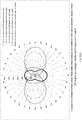
- Fig. 2(A) is a graph of the relative change in anisotropy ratio as the included angle of a bend in the marker is reduced. The measurements were taken using the test arrangement in Fig. 2(B) .
- the graph ( Fig. 2A ) shows that there is an optimum angle for a uniform signal when the angle is between 0° and 90°, and more preferably between 0° and 45°.
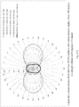
- Fig. 2(C) is a graph that shows how the signal varies with the angle of sensing relative to the marker's main axis for iron markers with different included angles.
- Fig. 2(D) is a graph that shows how the signal varies with the angle of sensing relative to the marker's main axis for iron markers with different included angles.
- the marker may assume the shape only after it has been deployed so that it can be packed more efficiently into the deployment needle prior to deployment.
- An elastic material or a section of elastic material may be used to facilitate this.
- Such shapes include, but are not limited to the following:
- the implanted marker is made primarily from a magnetically soft material and the marker has a long thin aspect ratio prior to deployment but changes configuration after deployment to a shape with a low anisotropy of the magnetic susceptibility.
- the marker Prior to deployment, the marker may have a length to diameter ratio or shape factor of greater than 5, and a ratio of magnetic anisotropy of susceptibility of greater than 5 or even greater than 7 or 9, such values resulting from the extended length of the marker prior to deployment and being beneficial to increase the volume of marker contained in the needle so as to maximize the magnetic response once deployed.
- the ratio of magnetic anisotropy of susceptibility is less than 5 and preferably less than 3, and ideally 2 or less to provide a more uniform magnetic response.
- the marker is elastically deformable or resiliently deformable such that it elastically or resiliently changes in shape and size from a packed or pre-deployment shape within the needle or deployment device with an associated shape factor, to a post-deployment shape and shape factor.
- the elasticity or resilience may, for example, derive from the use of an elastic or resilient material or from an elastic, resilient or deployable structure or combinations thereof.
- the magnetic marker is elastically or resiliently deformable between a packed configuration having a higher anisotropy of magnetic susceptibility, and a deployed / unpacked configuration having a lower anisotropy of magnetic susceptibility.
- the magnetic marker is elastically or resiliently deformable between a packed configuration having a higher projected area anisotropy ratio, and a deployed / unpacked configuration having a lower projected area anisotropy ratio.
- the deployed or delivered configuration of the marker has an anisotropy of magnetic susceptibility of less than 5, more preferably less than 3 and ideally less than 2 in order to give the most uniform detection signal; while prior to deployment within the delivery device, the marker in its packed configuration has an anisotropy of magnetic susceptibility of greater than 5 and more preferably greater than 7, in order to maximize the volume of material in the marker given the constrained diameter of the delivery device.
- the marker in its packed configuration has a projected area anisotropy ratio of greater than 5 and more preferably greater than 7; but in a deployed / unpacked configuration has a projected area anisotropy ratio of less than 5, more preferably less than 3 and ideally less than 2.
- the marker requires a degree of resilience whereby one dimension (e.g., the diameter perpendicular to the main axis) of the marker changes by a factor of, at least, 1.5 times from its packed value to its deployed value.
- the deployed dimension is larger than the packed dimension by a factor of greater than 2 and more preferably greater than 3 in order to provide a shape factor (ratio of maximum dimension to minimum dimension) close to 1 or 2 on deployment, while still having sufficient material to be detected.
- the magnetic marker in its packed configuration is packed within a delivery device prior to use.
- the delivery device needs to be able to deliver the marker through the skin to mark the tissue area of interest, for example a cancerous lesion.
- Suitable delivery devices include any needle- or cannula-based delivery system, typically comprising a needle and means to propel the marker through the end or out of the side of the needle such as a plunger or stylet.
- the needle is preferably 14 to 18 gauge. This means that the needle has an internal diameter generally of 0.8mm to 1.5mm but may possibly be as large as 1.8mm for certain needle designs. Preferably it is between 1.0 and 1.5mm in diameter. If a vacuum-assisted needle is used, the needle size is typically 11 gauge, with an internal diameter of 2.3 to 2.5 mm.
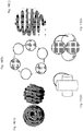
- Markers that achieve the desired change in anisotropy of the magnetic susceptibility between their packed and unpacked configurations include, but are not limited to the following:
- a ball of yarn is preferably formed from a material with a large magnetic response such as a metallic glass or a magnetically soft material from the list above.
- the ball may be formed from a fine wire of diameter for example between 10 ⁇ m and 250 ⁇ m and length for example of between 5 mm and 150 mm, and bent into the shape of the ball.
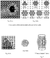
- the marker may be elastically deformable or resiliently deformable. The marker is compressed to fit inside the deployment needle or delivery device, where, prior to delivery, it may be constrained to take a more cylindrical shape. On deployment the ball expands to close to its original size and takes a substantially spherical shape. Table 3 shows that this marker can achieve an anisotropy ratio of close to the ideal of 1.
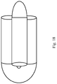
- This marker forms ( Fig. 7 ). On deployment, this marker is arranged such that it resiliently reconfigures from a cylinder to a more compressed lantern configuration, thus increasing the uniformity of the magnetic response (reducing anisotropy) because the amount of material in the transverse axis is increased from that of a cylinder.
- the multiple facets also provide superior ultrasound response.
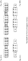
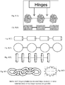
- Markers comprising a plurality of magnetically soft elements joined with hinges as shown in Fig. 8(A)-(G) that deform into shape on deployment (either plastically, pre-stressed or through the action of a shape-memory in the material).
- the greater length of the marker in this embodiment is possible because the shape of the marker in the deployment needle is linear but folds to another configuration upon injection into a site. This reduces the anisotropy by providing a substantially uniform amount of magnetic material in any given axis of the marker.
- the multiple facets also provide superior ultrasound response. It is desirable to have at least 3 elements to obtain a uniform response, and many more may be added, although for complexity the number is preferably less than 20 and more preferably less than 10.
- the hinged and other flexible or resiliently deformable forms may comprise a plurality of smaller magnetic units or components joined by non-magnetic flexible or resiliently deformable links such as plastic or shape memory materials. Combinations of these forms, e.g., bent wire made from multi-strand cable, are also included. As shown in Table 3, a marker of this kind with multiple ball elements and a pre-deployment geometric length:diameter ratio of 8 can have a post-deployment magnetic anisotropy of susceptibility of less than 2.
- Markers comprising a plurality of elements joined with collapsible links between them such that on deployment the elements collapse together to form an amorphous region with a low ratio of magnetic anisotropy of susceptibility.
- the links can be formed from a string-like material such as suture or other polymer.
- the magnetically soft elements are links in a chain that can collapse on itself after deployment.
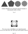
- Markers comprising a springy or resiliently deformable wire, or cylindrical shape prior to deployment that on deployment forms a structure or wireframe.
- Such structures may include a cylindrical coil, helix, conical coil, spherical coil, random 'ball of yarn', or a polyhedron such as a tetrahedron or part thereof.
- Markers comprising a resiliently deformable looped or shaped coil spring that is compressed prior to deployment and expands upon deployment to a shape with a low ratio of magnetic anisotropy of susceptibility.
- a coil spring shaped into a circle gives a surprisingly low ratio of magnetic anisotropy of susceptibility (Table 3).
- the ratio of the circle diameter to the spring coil diameter is less than 5 in order to maintain a more uniform magnetic response.
- Markers comprising two or more elements connected by a link formed from an elastic or resiliently deformable or springy material such that the elements once deployed spring into a new configuration giving a low magnetic anisotropy of susceptibility.
- Table 4 illustrates one such embodiment comprising two short cylindrical elements formed of magnetically soft material joined by a spring filament.
- the filament is biased such that on deployment the two elements spring back across each other to approximate a tetrahedral shape with a low ratio of magnetic anisotropy of susceptibility of less than 2.
- the spring filament may be formed from a spring steel, shape memory material or other elastic or resiliently deformable material.
- the length of the cylindrical elements is between 2 and 5 times their diameter to provide good uniformity of response combined with a compact shape.
- multiple elements on a springy material are deployed from the needle and the springy material is biased such that on deployment the elements are formed into a structure.
- Example structures may include a cylindrical coil, helix, conical coil, spherical coil, random 'ball of yarn', or a tetrahedron or part thereof.
- the length of the marker when in its packed configuration may be between 2 and 5 times their diameter but could be even greater e.g. up to 10 or more times the diameter depending on the degree of elasticity of the structure of material being used, thus allowing more magnetic material to be deployed to maximize the detectability of the marker.
- a further benefit of the "ball of yarn" ( Fig. 6 ) stranded or multi-facetted forms is superior visibility to such reflective imaging techniques as ultrasound, IR or ultra-wideband radar.
- These benefits can also be realised by revision of the external surface of the other forms mentioned, including the non-hinge sections of the hinged forms ( Fig. 7 ) from cylindrical to facetted or grooved forms such as, but not limited to, triangular, pentagonal, dodecagon, cog-like cross sections ( Fig. 9 ).
- a similar effect can be observed in ultrasound from sintered materials such as ferrites.
- Correct choice of soft material in any of the forms mentioned can provide visibility to X-ray imaging. Interlocked U's take similar space to U but with increased signal and reduced anisotropy ( Fig. 18 ).
- the ratio of magnetic anisotropy of susceptibility of the implanted marker is modified by varying the magnetic properties of the magnetically soft material forming the marker along its length.
- the reduction in magnetic anisotropy of susceptibility can be achieved through use of composite materials such as the formation of ferrite via sintering with two or more materials where at least one material is a soft material distributed to provide a less anisotropic response. Similar forms can be created, as previously mentioned, where multiple materials are used within the marker.
- One such embodiment is a single segmented marker with a constant cross section.
- an additional benefit of this aspect of the invention is that the soft distribution or shape can be independent of the external form and cross sections which improve imaging visibility under ultrasound or X-ray can be created.
- Further examples of composite magnetic markers with decreased anisotropy include soft markers distributed on a collapsible stent-like structure specifically those that are self-expanding.
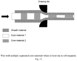
- embodiments include hollow versions where the individual wires are formed from different materials or formed from composite material, e.g., a core and a covering or sheath material where at least one or more of these are magnetically soft materials.
- a specific example of this is where the core or covering material is made from Nitinol or other shape memory material (including shape memory polymers) which is used to form the post deployment shape ( Fig. 10 ).
- the core or covering material is made from Nitinol or other shape memory material (including shape memory polymers) which is used to form the post deployment shape ( Fig. 10 ).
- the wires or one of the segments multi-core wires could also be used to provide improved X-ray visibility.
- Figs. 12(A) and (B) are examples of segmented marker (note: more or fewer segments are possible).
- the segmentation increases losses between sections in the axial direction and manages the opposing eddy current effect, reducing the anisotropy.
- Figs 13(A) and (B) show examples of soft material (dark grey) that may be moulded into a shape that is independent of the external shape of the marker (note: more than two materials could be used within the construction). Anisotropy is improved by providing more magnetic material in the transverse axis and reducing the opposing eddy current through combination of the materials selected.
- the magnetically soft core is formed from a material with a very high magnetic response such as a metallic glass such that sufficient magnetic response can be obtained from only a very small sphere of the material.
- the core is encased in a protective layer comprising a biocompatible coating or capsule, for example a titanium shell or a biocompatible polymer coating. Because the core is spherical, the ratio of magnetic anisotropy of susceptibility is close to 1.
- Figs. 14 Shaped markers with hinges of plastic/pre-stressed/shape memory in multiple materials with different magnetic properties are shown in Figs. 14 (A-E). These configurations improve the tailoring of the response in order to reduce the anisotropy by providing a substantially uniform response in any given axis of the marker. The multiple facets also provide superior ultrasound response.
- a long thin marker is divided into a number of smaller markers.
- the multiple markers that are packed together prior to deployment have the same overall dimensions and material, and can be used to decrease the anisotropy relative to the overall dimensions of the material.
- 3 x 2mm long or 2 x 3mm long or 6 x 1mm long marker pieces have decreased anisotropy in comparison to 1 x 6mm long marker of the same outer diameter.
- this reduction in anisotropy occurs even when the segments align one behind each other in the same shape as an individual marker of the combined dimensions.
- Table 5 For example, a single marker of dimension 5mm in ferritic stainless steel gives an anisotropy ratio of 6.7.
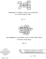
- a set of markers or magnetic particles produced from magnetically soft material can retain a small amount of magnetism. Once deployed into the patient, these magnetic particles can then self-assemble into an associated magnetic marker which possesses lower magnetic anisotropy of susceptibility. Multiple magnetically soft markers with a small magnetic remanence will self-assemble into an associated magnetic marker with a substantially uniform amount of material in every direction, thereby minimising anisotropy ( Fig. 15 ). This small magnetic remanence can be overcome by the magnetic excitation of the exciting field of the magnetometer (or susceptometer) as described above. Table 6 shows the parameters of particles assembled by two types of magnetic compositions.
- magnetically soft markers or particles encased within hydrophobic surfaces (nano-texturing via lotus effect, silica nano-coatings, EnBio CoBlast PTFE, Hydroxyapitite, carbon nanotube coatings, precipitate calcium carbide & fatty acid coating with polymer latex, manganese oxide polystyrene or zinc oxide polystyrene nano-composites) or spheres will pull together (self-assemble) on deployment into the patient.
- this embodiment will form a close-packed shape such as a sphere or ellipsoid system which will have an improved magnetic anisotropy of susceptibility relative to the particles within the delivery system which will constrain in an elongated shape to be elongated.
- Fig. 16 depicts hydrophobic coated markers or particles which self-assemble, to minimise surface energy, into an associated magnetic marker with a substantially uniform amount of material in every direction minimising anisotropy.
- small micromarkers or microparticles of a soft material can be suspended within a biocompatible matrix ( Figs. 17(A) and (B) ).
- Control of the magnetic particle distribution in a similar manner as discussed with respect to Figs. 10-12 , allows a decreased magnetic anisotropy of susceptibility as well as the independence from the outer form. It can also be used to ensure a set location and orientation between the magnetic markers.
- the gel and particles can be deployed through the deployment needle ( Fig. 17(B) ).
- the shape of the deployed gel and particles will be constrained only by the injection site (i.e. the tissue of a lesion) which is less in comparison to that of the needle.
- This gel can also set on injection making it less likely to migrate from its deployed location and easier to remove surgically if the tissue is being removed.
- the addition of other particles such as gold to provide additional radiopaque response for x-ray visualisation could be performed if required.
- the anisotropy should be less than or equal to 9, preferably less than or equal to 6, more preferably less than or equal to 3.
- the present : disclosure provides various ways of making magnetic markers with acceptable anisotropy while not affecting the ease of delivery of the particles.
- a method for marking a soft tissue site of interest, such as the site of a tumor or benign lesion for example within the breast, lung, bowel/colon, rectum, prostate or other cancer affected organ, or a lymph node within the axilla or other nodal basin within the body.
- the method includes the steps of (i) inserting such a magnetic marker into tissue near the target lesion or site, and (ii) detecting such a marker using a susceptometer, and optionally (iii) surgically excising the target tissue around the marker.
- the susceptometer detects the marker by providing a magnetic field in the region of the marker and measuring the induced magnetization in the marker.
Landscapes
- Health & Medical Sciences (AREA)
- Life Sciences & Earth Sciences (AREA)
- Surgery (AREA)
- Engineering & Computer Science (AREA)
- Pathology (AREA)
- Veterinary Medicine (AREA)
- Biomedical Technology (AREA)
- Heart & Thoracic Surgery (AREA)
- Medical Informatics (AREA)
- Molecular Biology (AREA)
- Animal Behavior & Ethology (AREA)
- General Health & Medical Sciences (AREA)
- Public Health (AREA)
- Nuclear Medicine, Radiotherapy & Molecular Imaging (AREA)
- Physics & Mathematics (AREA)
- Biophysics (AREA)
- Oral & Maxillofacial Surgery (AREA)
- Radiology & Medical Imaging (AREA)
- Gynecology & Obstetrics (AREA)
- Reproductive Health (AREA)
- Power Engineering (AREA)
- Chemical & Material Sciences (AREA)
- Dispersion Chemistry (AREA)
- Medicines Containing Antibodies Or Antigens For Use As Internal Diagnostic Agents (AREA)
- Materials For Medical Uses (AREA)
- Measurement And Recording Of Electrical Phenomena And Electrical Characteristics Of The Living Body (AREA)
- Magnetic Treatment Devices (AREA)
- Magnetic Resonance Imaging Apparatus (AREA)
- Hard Magnetic Materials (AREA)
- Soft Magnetic Materials (AREA)
- Media Introduction/Drainage Providing Device (AREA)
- Geophysics And Detection Of Objects (AREA)
- Ropes Or Cables (AREA)
- Measurement Of Length, Angles, Or The Like Using Electric Or Magnetic Means (AREA)
Priority Applications (2)
| Application Number | Priority Date | Filing Date | Title |
|---|---|---|---|
| EP22176363.4A EP4085866A3 (en) | 2015-06-04 | 2016-06-03 | Marker materials and forms for magnetic marker localization |
| EP20180295.6A EP3782575A1 (en) | 2015-06-04 | 2016-06-03 | Marker materials and forms for magnetic marker localization (mml) |
Applications Claiming Priority (2)
| Application Number | Priority Date | Filing Date | Title |
|---|---|---|---|
| US201562170768P | 2015-06-04 | 2015-06-04 | |
| PCT/GB2016/051649 WO2016193753A2 (en) | 2015-06-04 | 2016-06-03 | Marker materials and forms for magnetic marker localization (mml) |
Related Child Applications (3)
| Application Number | Title | Priority Date | Filing Date |
|---|---|---|---|
| EP20180295.6A Division EP3782575A1 (en) | 2015-06-04 | 2016-06-03 | Marker materials and forms for magnetic marker localization (mml) |
| EP20180295.6A Division-Into EP3782575A1 (en) | 2015-06-04 | 2016-06-03 | Marker materials and forms for magnetic marker localization (mml) |
| EP22176363.4A Division EP4085866A3 (en) | 2015-06-04 | 2016-06-03 | Marker materials and forms for magnetic marker localization |
Publications (2)
| Publication Number | Publication Date |
|---|---|
| EP3302338A2 EP3302338A2 (en) | 2018-04-11 |
| EP3302338B1 true EP3302338B1 (en) | 2020-09-30 |
Family
ID=56119700
Family Applications (3)
| Application Number | Title | Priority Date | Filing Date |
|---|---|---|---|
| EP16728722.6A Active EP3302338B1 (en) | 2015-06-04 | 2016-06-03 | Marker materials and forms for magnetic marker localization |
| EP20180295.6A Pending EP3782575A1 (en) | 2015-06-04 | 2016-06-03 | Marker materials and forms for magnetic marker localization (mml) |
| EP22176363.4A Pending EP4085866A3 (en) | 2015-06-04 | 2016-06-03 | Marker materials and forms for magnetic marker localization |
Family Applications After (2)
| Application Number | Title | Priority Date | Filing Date |
|---|---|---|---|
| EP20180295.6A Pending EP3782575A1 (en) | 2015-06-04 | 2016-06-03 | Marker materials and forms for magnetic marker localization (mml) |
| EP22176363.4A Pending EP4085866A3 (en) | 2015-06-04 | 2016-06-03 | Marker materials and forms for magnetic marker localization |
Country Status (10)
| Country | Link |
|---|---|
| US (4) | US10595957B2 (cg-RX-API-DMAC7.html) |
| EP (3) | EP3302338B1 (cg-RX-API-DMAC7.html) |
| JP (1) | JP6821665B2 (cg-RX-API-DMAC7.html) |
| KR (1) | KR102589814B1 (cg-RX-API-DMAC7.html) |
| CN (2) | CN113558782B (cg-RX-API-DMAC7.html) |
| AU (1) | AU2016272550B2 (cg-RX-API-DMAC7.html) |
| CA (1) | CA2988065C (cg-RX-API-DMAC7.html) |
| ES (1) | ES2833377T3 (cg-RX-API-DMAC7.html) |
| MX (1) | MX390935B (cg-RX-API-DMAC7.html) |
| WO (1) | WO2016193753A2 (cg-RX-API-DMAC7.html) |
Families Citing this family (22)
| Publication number | Priority date | Publication date | Assignee | Title |
|---|---|---|---|---|
| US9936892B1 (en) | 2009-05-04 | 2018-04-10 | Cortex Manufacturing Inc. | Systems and methods for providing a fiducial marker |
| US11883246B2 (en) | 2012-11-21 | 2024-01-30 | Trustees Of Boston University | Tissue markers and uses thereof |
| WO2016193185A1 (en) * | 2015-06-04 | 2016-12-08 | Koninklijke Philips N.V. | Determination of positions of objects, such as brachytherapy seeds |
| CN105852984B (zh) * | 2016-03-23 | 2020-02-18 | 堃博生物科技(上海)有限公司 | 肺内标记物 |
| CN118542741A (zh) * | 2016-09-09 | 2024-08-27 | 森尼布鲁克研究所 | 用于磁性隐匿病变定位和成像的系统和方法 |
| GB2582123B (en) | 2018-01-25 | 2021-04-28 | Endomagnetics Ltd | Systems and methods for detecting magnetic markers for surgical guidance |
| GB2573500B (en) * | 2018-03-23 | 2020-11-04 | Endomagnetics Ltd | Magnetic markers for surgical guidance |
| WO2020077207A1 (en) | 2018-10-12 | 2020-04-16 | Focal Therapeutics Inc. | Tissue localization device and method of use thereof |
| US11266481B2 (en) | 2018-10-12 | 2022-03-08 | Hologic, Inc. | Tissue localization marker with D-shaped cross-section |
| WO2020154934A1 (zh) * | 2019-01-30 | 2020-08-06 | 唐山哈船科技有限公司 | 手术辅助定位器 |
| KR102251651B1 (ko) * | 2019-03-19 | 2021-05-14 | 오스템임플란트 주식회사 | 파노라믹 영상 생성을 위한 커브 라인 자동 생성방법 및 이를 위한 치과영상 처리장치 |
| EP3946135B1 (en) * | 2019-05-30 | 2023-12-27 | Devicor Medical Products, Inc. | Biopsy site marker for limited migration |
| GB2585034A (en) * | 2019-06-25 | 2020-12-30 | Endomagnetics Ltd | Hyperthermia implants and a method and system for heating the implant |
| WO2021005955A1 (ja) * | 2019-07-10 | 2021-01-14 | 京都府公立大学法人 | 医療用イメージガイダンスマーカー |
| US20230329832A1 (en) * | 2019-10-23 | 2023-10-19 | Clemson University | A Breast Tissue Marker and Localization System |
| US11166782B1 (en) * | 2020-07-19 | 2021-11-09 | Sirius Medical Systems B.V. | Implantable marker and a method of implanting markers |
| WO2022075911A1 (en) * | 2020-10-07 | 2022-04-14 | Camtomsam AB | Radiation therapy reference positioning marker |
| US12357417B2 (en) | 2021-07-30 | 2025-07-15 | Matrix Cell Research Institute Inc. | Magnetic marker set and method of arranging magnetic marker |
| GB2612597B8 (en) * | 2021-11-03 | 2025-02-12 | Endomagnetics Ltd | Improvements in or relating to implantable ferromagnetic markers |
| GB2612598B8 (en) * | 2021-11-03 | 2025-02-12 | Endomagnetics Ltd | Magnetic markers for imaging and surgical guidance |
| GB2620722B (en) | 2022-04-05 | 2024-12-04 | Endomagnetics Ltd | Improvements in or relating to susceptibility probes for detecting surgical markers |
| GB2617357B (en) | 2022-04-05 | 2024-09-11 | Endomagnetics Ltd | Improvements in or relating to susceptibility probes for detecting surgical markers |
Family Cites Families (180)
| Publication number | Priority date | Publication date | Assignee | Title |
|---|---|---|---|---|
| US2614164A (en) | 1947-11-12 | 1952-10-14 | Schlumberger Well Surv Corp | Mutual inductance system |
| US3449662A (en) | 1963-10-16 | 1969-06-10 | American Mach & Foundry | Magnetic inspection method and apparatus using resilient magnetizing means and resilient sensors |
| US3445928A (en) | 1966-03-25 | 1969-05-27 | Bunker Ramo | Magnetometer method of manufacture |
| US3492566A (en) | 1967-09-01 | 1970-01-27 | Canadian Patents Dev | Three dimensional magnetic anisotropic susceptibility meter |
| US4324255A (en) | 1980-03-07 | 1982-04-13 | Barach John P | Method and apparatus for measuring magnetic fields and electrical currents in biological and other systems |
| GB2109112A (en) | 1981-10-06 | 1983-05-25 | Pantatron Systems Limited | Eddy current test probe |
| JPH0768117B2 (ja) | 1983-05-06 | 1995-07-26 | ベスター・インコーポレイテツド | 薬剤放出調整用小胞製剤 |
| US4823113A (en) * | 1986-02-27 | 1989-04-18 | Allied-Signal Inc. | Glassy alloy identification marker |
| US5055288A (en) | 1987-06-26 | 1991-10-08 | Advanced Magnetics, Inc. | Vascular magnetic imaging method and agent comprising biodegradeable superparamagnetic metal oxides |
| US5261403A (en) | 1987-03-30 | 1993-11-16 | Hitachi, Ltd. | Magnetic resonance imaging apparatus |
| US5414356A (en) | 1987-09-21 | 1995-05-09 | Hitachi, Ltd. | Fluxmeter including squid and pickup coil with flux guiding core and method for sensing degree of deterioration of an object |
| US4825162A (en) | 1987-12-07 | 1989-04-25 | General Electric Company | Nuclear magnetic resonance (NMR) imaging with multiple surface coils |
| JP2613275B2 (ja) | 1988-09-16 | 1997-05-21 | 株式会社日立製作所 | 超電導量子干渉素子を用いた磁束計 |
| EP0390935A1 (de) | 1989-03-29 | 1990-10-10 | Siemens Aktiengesellschaft | Verfahren zum Kalibrieren von Mehrkanal-Squid-Systemen mit Gradiometern beliebiger Ordnung |
| US5442289A (en) | 1989-07-31 | 1995-08-15 | Biomagnetic Technologies, Inc. | Biomagnetometer having flexible sensor |
| DE4003330A1 (de) | 1990-02-05 | 1991-08-08 | Foerster Inst Dr Friedrich | Wirbelstrompruefgeraet |
| US5005001A (en) | 1990-04-05 | 1991-04-02 | Pitney Bowes Inc. | Field generation and reception system for electronic article surveillance |
| US5512821A (en) | 1991-06-04 | 1996-04-30 | Nkk Corporation | Method and apparatus for magnetically detecting defects in an object with compensation for magnetic field shift by means of a compensating coil |
| US5293119A (en) | 1992-02-20 | 1994-03-08 | Sqm Technology, Inc. | Electromagnetic microscope for evaluation of electrically conductive and magnetic materials |
| JP2882167B2 (ja) | 1992-03-06 | 1999-04-12 | ダイキン工業株式会社 | Squid磁束計 |
| FR2689638B1 (fr) | 1992-04-06 | 1996-08-09 | Aerospatiale | Capteur a courants de foucault. |
| US5313192A (en) * | 1992-07-02 | 1994-05-17 | Sensormatic Electronics Corp. | Deactivatable/reactivatable magnetic marker having a step change in magnetic flux |
| WO1994003501A1 (fr) | 1992-08-05 | 1994-02-17 | Meito Sangyo Kabushiki Kaisha | Composite de petit diametre constitue de carboxypolysaccharide hydrosoluble et d'oxyde de fer magnetique |
| DE4226814A1 (de) | 1992-08-13 | 1994-02-17 | Philips Patentverwaltung | Spulenanordnung für MR-Untersuchungen der Mamma |
| US6023165A (en) | 1992-09-28 | 2000-02-08 | Fonar Corporation | Nuclear magnetic resonance apparatus and methods of use and facilities for incorporating the same |
| US5575794A (en) | 1993-02-12 | 1996-11-19 | Walus; Richard L. | Tool for implanting a fiducial marker |
| JPH06324021A (ja) | 1993-03-16 | 1994-11-25 | Hitachi Ltd | 非破壊検査装置 |
| US5537037A (en) | 1993-03-16 | 1996-07-16 | Hitachi, Ltd. | Apparatus with cancel coil assembly for cancelling a field parallel to an axial direction to the plural coils and to a squid pick up coil |
| DE9422172U1 (de) | 1993-04-26 | 1998-08-06 | St. Louis University, St. Louis, Mo. | Angabe der Position einer chirurgischen Sonde |
| US5590654A (en) | 1993-06-07 | 1997-01-07 | Prince; Martin R. | Method and apparatus for magnetic resonance imaging of arteries using a magnetic resonance contrast agent |
| US5363845A (en) | 1993-08-13 | 1994-11-15 | Medical Advances, Inc. | Breast coil for magnetic resonance imaging |
| BE1007459A3 (nl) | 1993-08-24 | 1995-07-04 | Philips Electronics Nv | Magnetisch resonantie apparaat. |
| US5437280A (en) | 1993-09-20 | 1995-08-01 | Hussman; Karl L. | Magnetic resonance breast localizer |
| JPH0815229A (ja) | 1994-06-27 | 1996-01-19 | Mitsubishi Heavy Ind Ltd | 高分解能渦電流探傷装置 |
| US5402094A (en) | 1994-08-15 | 1995-03-28 | Enge; Harald A. | MRI mammography magnet |
| CA2199864C (en) | 1994-09-16 | 2006-06-20 | Seth A. Foerster | Methods and devices for defining and marking tissue |
| DE19503664C2 (de) * | 1995-01-27 | 1998-04-02 | Schering Ag | Magnetorelaxometrische Detektion von Analyten |
| JP3910222B2 (ja) | 1995-03-10 | 2007-04-25 | 株式会社豊田中央研究所 | 疲労度測定装置 |
| US5657756A (en) | 1995-06-07 | 1997-08-19 | Ctf Systems Inc. | Method and systems for obtaining higher order gradiometer measurements with lower order gradiometers |
| JP3580905B2 (ja) | 1995-06-13 | 2004-10-27 | 大日本印刷株式会社 | 磁気センサ |
| JP3499054B2 (ja) | 1995-07-11 | 2004-02-23 | 独立行政法人 国立印刷局 | 安全保護紙の真偽判定装置 |
| US5842986A (en) | 1995-08-16 | 1998-12-01 | Proton Sciences Corp. | Ferromagnetic foreign body screening method and apparatus |
| DE19532676C1 (de) | 1995-09-05 | 1997-05-07 | Inst Physikalische Hochtech Ev | Anordnung zur Bestimmung der Position eines Markers in einem Hohlraum innerhalb des Organismus eines Lebewesens |
| WO1997026862A2 (de) | 1996-01-25 | 1997-07-31 | Schering Aktiengesellschaft | Verbesserte konzentrierte injektions- und infusionslösungen für die intravasale anwendung |
| CN1213316A (zh) | 1996-03-11 | 1999-04-07 | 富克尔公司 | 放射性核素及放射性医药品的聚合物输送 |
| JPH1038854A (ja) | 1996-07-17 | 1998-02-13 | Agency Of Ind Science & Technol | 導電性材料の非破壊検査方法および装置 |
| EP1284123B1 (en) | 1996-08-12 | 2005-07-20 | Ethicon Endo-Surgery, Inc. | Apparatus for marking tissue |
| AU4070697A (en) | 1996-08-16 | 1998-03-06 | Jon Neal Weaver | Anti-shoplifting security system |
| US5844140A (en) | 1996-08-27 | 1998-12-01 | Seale; Joseph B. | Ultrasound beam alignment servo |
| US5997473A (en) | 1996-09-06 | 1999-12-07 | Olympus Optical Co., Ltd. | Method of locating a coil which consists of determining the space occupied by a source coil generating a magnetic field |
| DE29724862U1 (de) | 1996-09-18 | 2004-12-30 | Ifm Electronic Gmbh | Induktiver Näherungsschalter |
| JP2001527641A (ja) | 1996-12-27 | 2001-12-25 | ベーイーツェー−ナイセ ゲゼルシャフト ミット ベシュレンクテル ハフツング ビジネス アンド イノヴェイション センター イン デア オイロレギオーン ナイセ | 磁気共振センサ |
| US6406420B1 (en) | 1997-01-02 | 2002-06-18 | Myocor, Inc. | Methods and devices for improving cardiac function in hearts |
| AU2869900A (en) | 1997-02-27 | 2000-08-25 | Uri Rapoport | Method and apparatus for detecting a magnetically responsive substance |
| GB9712524D0 (en) | 1997-06-16 | 1997-08-20 | Nycomed Imaging As | Method |
| FR2770779B1 (fr) | 1997-11-10 | 2000-07-21 | Bernstein Veronique | Solute hypotonique ou hypoosmolaire au plasma utilise dans le traitement de la cellulite, les fibroses, et de l'hirsutisme |
| US6270464B1 (en) | 1998-06-22 | 2001-08-07 | Artemis Medical, Inc. | Biopsy localization method and device |
| US6205352B1 (en) | 1997-11-19 | 2001-03-20 | Oncology Innovations, Inc. | Sentinel node identification using non-isotope means |
| CA2260703A1 (en) | 1998-04-07 | 1999-10-07 | Dennis W. Szymaitis | Disposal container for detecting, distinguishing and counting objects |
| US6161034A (en) | 1999-02-02 | 2000-12-12 | Senorx, Inc. | Methods and chemical preparations for time-limited marking of biopsy sites |
| US6347241B2 (en) | 1999-02-02 | 2002-02-12 | Senorx, Inc. | Ultrasonic and x-ray detectable biopsy site marker and apparatus for applying it |
| US5941890A (en) | 1998-06-26 | 1999-08-24 | Ethicon Endo-Surgery, Inc. | Implantable surgical marker |
| JP3957458B2 (ja) * | 1998-11-26 | 2007-08-15 | 株式会社Neomax | フェライト磁石粉末の製造方法および磁石の製造方法 |
| US6356782B1 (en) | 1998-12-24 | 2002-03-12 | Vivant Medical, Inc. | Subcutaneous cavity marking device and method |
| US6371904B1 (en) | 1998-12-24 | 2002-04-16 | Vivant Medical, Inc. | Subcutaneous cavity marking device and method |
| US6230038B1 (en) | 1999-02-01 | 2001-05-08 | International Business Machines Corporation | Imaging of internal structures of living bodies by sensing implanted magnetic devices |
| US6862470B2 (en) | 1999-02-02 | 2005-03-01 | Senorx, Inc. | Cavity-filling biopsy site markers |
| US7983734B2 (en) | 2003-05-23 | 2011-07-19 | Senorx, Inc. | Fibrous marker and intracorporeal delivery thereof |
| US6725083B1 (en) | 1999-02-02 | 2004-04-20 | Senorx, Inc. | Tissue site markers for in VIVO imaging |
| US6173715B1 (en) | 1999-03-01 | 2001-01-16 | Lucent Medical Systems, Inc. | Magnetic anatomical marker and method of use |
| GB9908179D0 (en) * | 1999-04-09 | 1999-06-02 | Univ Cambridge Tech | Magnetic materials |
| EP1171032A4 (en) | 1999-04-15 | 2008-10-29 | Surgi Vision | PROCESS FOR IN VIVO IMAGING BY MAGNETIC RESONANCE |
| EP2025350A3 (en) | 1999-04-21 | 2009-12-09 | The Government of the United States of America as represented by the Secretary of the Department of Health and Human Services | Determining pH by CEDST MRI |
| US6292678B1 (en) * | 1999-05-13 | 2001-09-18 | Stereotaxis, Inc. | Method of magnetically navigating medical devices with magnetic fields and gradients, and medical devices adapted therefor |
| US6766186B1 (en) | 1999-06-16 | 2004-07-20 | C. R. Bard, Inc. | Post biospy tissue marker and method of use |
| JP2001000430A (ja) | 1999-06-24 | 2001-01-09 | Alcare Co Ltd | 画像撮影用のマ−カ− |
| WO2001008578A1 (en) * | 1999-07-30 | 2001-02-08 | Vivant Medical, Inc. | Device and method for safe location and marking of a cavity and sentinel lymph nodes |
| US6835572B1 (en) | 1999-10-18 | 2004-12-28 | Institute For Magnetic Resonance Research | Magnetic resonance spectroscopy of breast biopsy to determine pathology, vascularization and nodal involvement |
| JP2001255358A (ja) | 2000-03-10 | 2001-09-21 | Sumitomo Electric Ind Ltd | 磁気センサ |
| US7283868B2 (en) | 2000-04-07 | 2007-10-16 | The Johns Hopkins University | Apparatus for sensing human prostate tumor |
| US6889073B2 (en) | 2000-05-08 | 2005-05-03 | David A. Lampman | Breast biopsy and therapy system for magnetic resonance imagers |
| JP2002004118A (ja) * | 2000-06-21 | 2002-01-09 | Unitika Ltd | 徘徊患者用衣服 |
| US6544269B2 (en) | 2000-08-10 | 2003-04-08 | Cook Incorporated | Localizer needle |
| US6394965B1 (en) | 2000-08-15 | 2002-05-28 | Carbon Medical Technologies, Inc. | Tissue marking using biocompatible microparticles |
| US7776310B2 (en) | 2000-11-16 | 2010-08-17 | Microspherix Llc | Flexible and/or elastic brachytherapy seed or strand |
| ATE456332T1 (de) | 2000-11-17 | 2010-02-15 | Calypso Medical Inc | System zur lokalisierung und definition einer zielposition in einem menschlichen körper |
| EP2319449B1 (en) | 2000-11-20 | 2016-03-09 | Senorx, Inc. | Tissue site markers for in vivo imaging |
| FR2823092B1 (fr) | 2001-04-10 | 2004-03-05 | Eurorad 2 6 | Dispositif per-operatoire pour la localisation de tissus marques et procede utilisant un tel dispositif |
| EP1383416A2 (en) * | 2001-04-18 | 2004-01-28 | BBMS Ltd. | Navigating and maneuvering of an in vivo vechicle by extracorporeal devices |
| JP4193382B2 (ja) | 2001-07-19 | 2008-12-10 | 株式会社日立製作所 | 磁場計測装置 |
| US6850065B1 (en) | 2001-07-27 | 2005-02-01 | General Electric Company | MRI coil system for breast imaging |
| US6592608B2 (en) | 2001-12-07 | 2003-07-15 | Biopsy Sciences, Llc | Bioabsorbable sealant |
| ITSV20010029A1 (it) | 2001-08-14 | 2003-02-14 | Esaote Spa | Macchina per il rilevamento di immagini in risonanza magnetica nucleare (mri) |
| US20030141868A1 (en) | 2001-08-23 | 2003-07-31 | Bakharev Alexander A. | High balance gradiometer |
| US7135978B2 (en) | 2001-09-14 | 2006-11-14 | Calypso Medical Technologies, Inc. | Miniature resonating marker assembly |
| US7701209B1 (en) | 2001-10-05 | 2010-04-20 | Fonar Corporation | Coils for horizontal field magnetic resonance imaging |
| JP4090722B2 (ja) | 2001-10-23 | 2008-05-28 | 純一 小川 | 磁性流体検出装置 |
| US20030216632A1 (en) | 2001-10-29 | 2003-11-20 | Mednovus, Inc. | Ferromagnetic sensing method and apparatus |
| JP2003149212A (ja) | 2001-11-09 | 2003-05-21 | Japan Science & Technology Corp | 非破壊検査装置 |
| US7787931B2 (en) | 2001-12-03 | 2010-08-31 | Fabian Carl E | Portable surgical implement detector |
| BR0214951A (pt) | 2001-12-14 | 2004-11-09 | Monteris Medical Inc | Tratamento de hipertermia e sonda para o mesmo |
| JP2003315373A (ja) | 2002-04-18 | 2003-11-06 | Toshiba Corp | 電流検出装置及び半導体装置 |
| US7329414B2 (en) | 2002-05-03 | 2008-02-12 | Biopsy Sciences, Llc | Biodegradable polymer for marking tissue and sealing tracts |
| JP4221192B2 (ja) | 2002-06-14 | 2009-02-12 | 株式会社日立ハイテクノロジーズ | 生体磁気計測装置 |
| US20040162477A1 (en) | 2002-10-04 | 2004-08-19 | Olympus Corporation | Apparatus for detecting magnetic fluid identifying sentinel-lymph node |
| US20060173283A1 (en) | 2002-11-27 | 2006-08-03 | Oskar Axelsson | Method of magnetic resonance imaging |
| DE60231925D1 (de) | 2002-12-13 | 2009-05-20 | E O Ospedali Galliera | Suszeptibilitätmessgerät zur nichtinvasiven messung des eisengehalts in einem körper |
| US7009398B2 (en) | 2003-03-20 | 2006-03-07 | Siemens Aktiengesellschaft | Portable magnetic resonance surface coil unit with an access opening for manual gripping |
| US20070010702A1 (en) * | 2003-04-08 | 2007-01-11 | Xingwu Wang | Medical device with low magnetic susceptibility |
| US7877133B2 (en) | 2003-05-23 | 2011-01-25 | Senorx, Inc. | Marker or filler forming fluid |
| US7783336B2 (en) | 2003-06-06 | 2010-08-24 | Ethicon Endo-Surgery, Inc. | Subcutaneous biopsy cavity marker device |
| US7744852B2 (en) | 2003-07-25 | 2010-06-29 | Rubicor Medical, Llc | Methods and systems for marking post biopsy cavity sites |
| US20050033157A1 (en) | 2003-07-25 | 2005-02-10 | Klein Dean A. | Multi-modality marking material and method |
| US7001341B2 (en) | 2003-08-13 | 2006-02-21 | Scimed Life Systems, Inc. | Marking biopsy sites |
| US7084631B2 (en) | 2003-11-19 | 2006-08-01 | General Electric Company | Magnetic resonance imaging array coil system and method for breast imaging |
| JP4217599B2 (ja) | 2003-12-09 | 2009-02-04 | オリンパス株式会社 | 磁性流体検出装置 |
| EP1541083A3 (en) | 2003-12-09 | 2006-03-01 | Olympus Corporation | Magnetic fluid detection device |
| US8118754B1 (en) | 2007-11-15 | 2012-02-21 | Flynn Edward R | Magnetic needle biopsy |
| US20050234336A1 (en) * | 2004-03-26 | 2005-10-20 | Beckman Andrew T | Apparatus and method for marking tissue |
| US7386338B2 (en) | 2004-04-30 | 2008-06-10 | General Electric Company | Bilateral imaging apparatus |
| US7708751B2 (en) | 2004-05-21 | 2010-05-04 | Ethicon Endo-Surgery, Inc. | MRI biopsy device |
| JP3896489B2 (ja) | 2004-07-16 | 2007-03-22 | 国立大学法人 岡山大学 | 磁気検知装置及び物質判定装置 |
| US7116094B2 (en) | 2004-07-28 | 2006-10-03 | International Business Machines Corporation | Apparatus and method for transmission and remote sensing of signals from integrated circuit devices |
| WO2006022786A1 (en) | 2004-08-20 | 2006-03-02 | David Mullen | Tissue marking devices and systems |
| US20060074295A1 (en) | 2004-10-01 | 2006-04-06 | Nexgen | Combined MR coil technology in medical devices |
| US8280486B2 (en) | 2004-10-13 | 2012-10-02 | Suros Surgical Systems, Inc. | Site marker visable under multiple modalities |
| US8060183B2 (en) | 2004-10-13 | 2011-11-15 | Suros Surgical Systems, Inc. | Site marker visible under multiple modalities |
| US20060079805A1 (en) * | 2004-10-13 | 2006-04-13 | Miller Michael E | Site marker visable under multiple modalities |
| WO2006055829A1 (en) | 2004-11-18 | 2006-05-26 | Nedim Turan Sahin | Mri as a therapeutic device |
| WO2006056739A2 (en) | 2004-11-23 | 2006-06-01 | Quantum Medical Technology Limited | Surgical tag, magnetometer, and associated system |
| WO2006067664A2 (en) | 2004-12-22 | 2006-06-29 | Philips Intellectual Property & Standards Gmbh | Marker for position determination with a magnetic method |
| CN101087556A (zh) * | 2004-12-22 | 2007-12-12 | 皇家飞利浦电子股份有限公司 | 确定磁性粒子的空间分布的装置和方法 |
| EP1842596B1 (en) * | 2004-12-22 | 2019-01-23 | Giamag Technologies AS | Substance separation device for forming a high-gradient magnetic field |
| DE102005002944A1 (de) * | 2005-01-18 | 2006-07-27 | Charité - Universitätsmedizin Berlin (Charité) | Endoskopisches Markierungsmittel sowie Instrumente zur Applikation und Detektion des Markierungsmittels sowie zur operativen Fixierung des markierten Gewebebereichs |
| US8467849B2 (en) | 2005-02-03 | 2013-06-18 | ORGAMEND Inc. | Magnetic resonance imaging device |
| US7842178B2 (en) * | 2005-04-18 | 2010-11-30 | University Of Iowa Research Foundation | Magnet incorporated electrically conductive electrodes |
| GB2425610A (en) | 2005-04-29 | 2006-11-01 | Univ London | Magnetic properties sensing system |
| US7831293B2 (en) | 2005-05-10 | 2010-11-09 | Advanced Clinical Solutions, Inc. | Method of defining a biological target for treatment |
| US20060293581A1 (en) | 2005-05-12 | 2006-12-28 | Sunnybrook And Women's College Health Sciences Centre | Marker device for X-ray, ultrasound and MR imaging |
| US7570056B2 (en) | 2005-08-10 | 2009-08-04 | Kabushiki Kaisha Toshiba | Magnetic resonance imaging apparatus |
| GB0519391D0 (en) | 2005-09-22 | 2005-11-02 | Aion Diagnostics Ltd | Imaging agents |
| WO2007041131A2 (en) * | 2005-09-30 | 2007-04-12 | Cook Incorporated | Coated vaso-occlusion device |
| US7479784B2 (en) | 2005-10-12 | 2009-01-20 | New York University | Arrangements, systems and methods for facilitating and collecting information associated with fluxes of magnetic fields provided at various angles from one another |
| EP3593790A1 (en) | 2005-11-01 | 2020-01-15 | Wyeth LLC | Sodium chloride solution for drug reconstitution or dilution |
| US8193804B2 (en) | 2005-11-16 | 2012-06-05 | Rex Chin-Yih Hong | Device for measuring AC magnetization of materials |
| US7702378B2 (en) | 2005-11-17 | 2010-04-20 | Breast-Med, Inc. | Tissue marker for multimodality radiographic imaging |
| US8078260B2 (en) | 2006-05-02 | 2011-12-13 | ORGAMEND Inc. | Method for improving magnetic resonance imaging of the breast |
| EP2079385B1 (en) | 2006-10-23 | 2013-11-20 | C.R.Bard, Inc. | Breast marker |
| US20090024022A1 (en) | 2006-10-25 | 2009-01-22 | Siemens Corporate Research, Inc. | System and method for lymph node imaging using co-registration of ct and mr imagery |
| US20080124281A1 (en) * | 2006-11-29 | 2008-05-29 | Board Of Regents, The University Of Texas System | Nanotubular probes as ultrasensitive mr contrast agent |
| US20080146914A1 (en) | 2006-12-19 | 2008-06-19 | General Electric Company | System, method and apparatus for cancer imaging |
| DE102007009016A1 (de) | 2007-02-23 | 2008-08-28 | Siemens Ag | Markierung und Verfahren zur Positionsbestimmung eines Zielgewebes |
| US20080228164A1 (en) | 2007-03-14 | 2008-09-18 | Nicoson Zachary R | Implant delivery system |
| US8239008B2 (en) | 2007-04-13 | 2012-08-07 | Ethicon Endo-Surgery, Inc. | Sentinel node identification using fluorescent nanoparticles |
| WO2008131391A1 (en) | 2007-04-23 | 2008-10-30 | Device Evolutions, Llc | Surgical metal detection apparatus and methods |
| US8137320B2 (en) | 2007-05-01 | 2012-03-20 | Suros Surgical Systems, Inc. | Securement for a surgical site marker and deployment device for same |
| US9763597B2 (en) | 2007-05-03 | 2017-09-19 | Wisconsin Alumni Research Foundation | Local MRI breast coil and method of use |
| US20090082662A1 (en) | 2007-09-24 | 2009-03-26 | Israel Henry M | Mri breast image magnet structure |
| DE102007046186A1 (de) | 2007-09-26 | 2009-04-02 | Amedo Smart Tracking Solutions Gmbh | Gewebemarkierung |
| US8731635B2 (en) | 2007-11-07 | 2014-05-20 | University of Pittsburgh—of the Commonwealth System of Higher Education | Coils for magnetic resonance spectroscopy and imaging of human breast |
| US8405477B2 (en) * | 2008-02-22 | 2013-03-26 | University Of Exeter | Controllable magnetic systems |
| DE102008015781B4 (de) * | 2008-03-26 | 2011-09-29 | Malte Neuss | Vorrichtung zum Verschluss von Defekten im Gefäßsystem |
| US8050742B2 (en) | 2008-07-30 | 2011-11-01 | Devicor Medical Products, Inc. | Biopsy device |
| DE102008048291B4 (de) | 2008-09-22 | 2012-02-16 | Siemens Aktiengesellschaft | Brustspulenanordnung für Magnetresonanzanwendungen |
| GB2465771A (en) | 2008-11-28 | 2010-06-02 | Helyn Margaret Wright | Surgical Localisation Device |
| EP2445402B1 (en) | 2009-06-26 | 2014-04-23 | Cianna Medical, Inc. | Apparatus, systems, and methods for localizing markers or tissue structures within a body |
| GB0916334D0 (en) | 2009-09-17 | 2009-10-28 | Renovo Ltd | Inhibition of tendon adhesions |
| US9427186B2 (en) | 2009-12-04 | 2016-08-30 | Endomagnetics Ltd. | Magnetic probe apparatus |
| US10634741B2 (en) | 2009-12-04 | 2020-04-28 | Endomagnetics Ltd. | Magnetic probe apparatus |
| JP5678565B2 (ja) | 2009-12-08 | 2015-03-04 | Jnc株式会社 | 磁性微粒子およびその製造方法 |
| US8870898B2 (en) | 2010-01-05 | 2014-10-28 | GI Windows, Inc. | Self-assembling magnetic anastomosis device having an exoskeleton |
| JP2012177691A (ja) * | 2011-02-04 | 2012-09-13 | Hitachi Maxell Ltd | 磁性マーカー粒子 |
| DE102011081445A1 (de) * | 2011-08-23 | 2013-02-28 | Epflex Feinwerktechnik Gmbh | Medizinischer Führungsdraht und Herstellungsverfahren |
| JP5924641B2 (ja) * | 2011-10-17 | 2016-05-25 | 学校法人東京電機大学 | 医療用チューブの先端位置検出システムおよび当該システムに適用する医療用チューブ |
| US8798716B1 (en) | 2011-11-03 | 2014-08-05 | Solstice Corporation | Fiducial markers and related methods |
| EP2809256B1 (en) | 2012-02-01 | 2017-07-12 | Koninklijke Philips N.V. | Multimodal fiducial marker and marker arrangement |
| US20140018663A1 (en) * | 2012-07-16 | 2014-01-16 | Endomagnetics Ltd. | Magnetic Marker for Surgical Localization |
| JP6351639B2 (ja) | 2013-03-11 | 2018-07-04 | エンドマグネティクス リミテッド | リンパ節検出のための低浸透圧溶液 |
| US9234877B2 (en) * | 2013-03-13 | 2016-01-12 | Endomagnetics Ltd. | Magnetic detector |
| JP6305869B2 (ja) * | 2014-08-19 | 2018-04-04 | 日立建機株式会社 | 建設機械用エンジン制御装置 |
-
2016
- 2016-06-03 JP JP2018515358A patent/JP6821665B2/ja active Active
- 2016-06-03 EP EP16728722.6A patent/EP3302338B1/en active Active
- 2016-06-03 CN CN202110644795.XA patent/CN113558782B/zh active Active
- 2016-06-03 KR KR1020187000167A patent/KR102589814B1/ko active Active
- 2016-06-03 US US15/172,187 patent/US10595957B2/en active Active
- 2016-06-03 MX MX2017015588A patent/MX390935B/es unknown
- 2016-06-03 CA CA2988065A patent/CA2988065C/en active Active
- 2016-06-03 WO PCT/GB2016/051649 patent/WO2016193753A2/en not_active Ceased
- 2016-06-03 EP EP20180295.6A patent/EP3782575A1/en active Pending
- 2016-06-03 ES ES16728722T patent/ES2833377T3/es active Active
- 2016-06-03 CN CN201680039792.0A patent/CN107920865B/zh active Active
- 2016-06-03 AU AU2016272550A patent/AU2016272550B2/en active Active
- 2016-06-03 EP EP22176363.4A patent/EP4085866A3/en active Pending
-
2019
- 2019-11-19 US US16/688,318 patent/US11504207B2/en active Active
-
2022
- 2022-11-16 US US17/988,146 patent/US12161513B2/en active Active
-
2024
- 2024-11-14 US US18/948,054 patent/US20250064548A1/en active Pending
Non-Patent Citations (1)
| Title |
|---|
| GROESSINGER R ET AL: "Frequency Dependence of the Coercivity of Soft Magnetic Materials", IEEE TRANSACTIONS ON MAGNETICS, IEEE SERVICE CENTER, NEW YORK, NY, US, vol. 48, no. 4, 1 April 2012 (2012-04-01), pages 1473 - 1476, XP011436600, ISSN: 0018-9464, DOI: 10.1109/TMAG.2011.2174351 * |
Also Published As
| Publication number | Publication date |
|---|---|
| US10595957B2 (en) | 2020-03-24 |
| WO2016193753A2 (en) | 2016-12-08 |
| EP4085866A2 (en) | 2022-11-09 |
| CN113558782A (zh) | 2021-10-29 |
| EP4085866A3 (en) | 2023-01-18 |
| AU2016272550A1 (en) | 2018-01-18 |
| MX390935B (es) | 2025-03-21 |
| MX2017015588A (es) | 2018-04-13 |
| EP3302338A2 (en) | 2018-04-11 |
| ES2833377T3 (es) | 2021-06-15 |
| US11504207B2 (en) | 2022-11-22 |
| KR102589814B1 (ko) | 2023-10-13 |
| WO2016193753A3 (en) | 2017-01-12 |
| US12161513B2 (en) | 2024-12-10 |
| US20160354178A1 (en) | 2016-12-08 |
| US20250064548A1 (en) | 2025-02-27 |
| CN107920865A (zh) | 2018-04-17 |
| EP3782575A1 (en) | 2021-02-24 |
| CN107920865B (zh) | 2021-07-09 |
| AU2016272550B2 (en) | 2021-01-28 |
| JP6821665B2 (ja) | 2021-01-27 |
| CA2988065C (en) | 2024-03-26 |
| CA2988065A1 (en) | 2016-12-08 |
| KR20180015234A (ko) | 2018-02-12 |
| US20230320811A1 (en) | 2023-10-12 |
| CN113558782B (zh) | 2024-12-10 |
| JP2018526160A (ja) | 2018-09-13 |
| US20200121415A1 (en) | 2020-04-23 |
Similar Documents
| Publication | Publication Date | Title |
|---|---|---|
| US12161513B2 (en) | Marker materials and forms for magnetic marker localization (MML) | |
| RU2754312C9 (ru) | Системы и способы обнаружения магнитных маркеров для контроля во время хирургического вмешательства | |
| JP2010517287A (ja) | 作用領域の磁性粒子に影響を与え及び/又はそれらを検出する方法、磁性粒子及び磁性粒子の使用 | |
| CN117580540B (zh) | 可植入铁磁标记的改进或与可植入铁磁标记相关的改进 | |
| EP4376761B1 (en) | Magnetic markers for imaging and surgical guidance | |
| JP2024541229A (ja) | 埋込型強磁性マーカーにおけるまたはそれに関する改良 |
Legal Events
| Date | Code | Title | Description |
|---|---|---|---|
| STAA | Information on the status of an ep patent application or granted ep patent |
Free format text: STATUS: THE INTERNATIONAL PUBLICATION HAS BEEN MADE |
|
| PUAI | Public reference made under article 153(3) epc to a published international application that has entered the european phase |
Free format text: ORIGINAL CODE: 0009012 |
|
| STAA | Information on the status of an ep patent application or granted ep patent |
Free format text: STATUS: REQUEST FOR EXAMINATION WAS MADE |
|
| 17P | Request for examination filed |
Effective date: 20180104 |
|
| AK | Designated contracting states |
Kind code of ref document: A2 Designated state(s): AL AT BE BG CH CY CZ DE DK EE ES FI FR GB GR HR HU IE IS IT LI LT LU LV MC MK MT NL NO PL PT RO RS SE SI SK SM TR |
|
| AX | Request for extension of the european patent |
Extension state: BA ME |
|
| DAV | Request for validation of the european patent (deleted) | ||
| DAX | Request for extension of the european patent (deleted) | ||
| STAA | Information on the status of an ep patent application or granted ep patent |
Free format text: STATUS: EXAMINATION IS IN PROGRESS |
|
| 17Q | First examination report despatched |
Effective date: 20190429 |
|
| GRAP | Despatch of communication of intention to grant a patent |
Free format text: ORIGINAL CODE: EPIDOSNIGR1 |
|
| STAA | Information on the status of an ep patent application or granted ep patent |
Free format text: STATUS: GRANT OF PATENT IS INTENDED |
|
| INTG | Intention to grant announced |
Effective date: 20200302 |
|
| RIN1 | Information on inventor provided before grant (corrected) |
Inventor name: HARMER, QUENTIN JOHN Inventor name: MAYES, ERIC Inventor name: LORIMER, KEVIN Inventor name: PANKHURST, QUENTIN ANDREW |
|
| GRAJ | Information related to disapproval of communication of intention to grant by the applicant or resumption of examination proceedings by the epo deleted |
Free format text: ORIGINAL CODE: EPIDOSDIGR1 |
|
| STAA | Information on the status of an ep patent application or granted ep patent |
Free format text: STATUS: EXAMINATION IS IN PROGRESS |
|
| INTC | Intention to grant announced (deleted) | ||
| GRAP | Despatch of communication of intention to grant a patent |
Free format text: ORIGINAL CODE: EPIDOSNIGR1 |
|
| STAA | Information on the status of an ep patent application or granted ep patent |
Free format text: STATUS: GRANT OF PATENT IS INTENDED |
|
| GRAS | Grant fee paid |
Free format text: ORIGINAL CODE: EPIDOSNIGR3 |
|
| INTG | Intention to grant announced |
Effective date: 20200731 |
|
| GRAA | (expected) grant |
Free format text: ORIGINAL CODE: 0009210 |
|
| STAA | Information on the status of an ep patent application or granted ep patent |
Free format text: STATUS: THE PATENT HAS BEEN GRANTED |
|
| AK | Designated contracting states |
Kind code of ref document: B1 Designated state(s): AL AT BE BG CH CY CZ DE DK EE ES FI FR GB GR HR HU IE IS IT LI LT LU LV MC MK MT NL NO PL PT RO RS SE SI SK SM TR |
|
| REG | Reference to a national code |
Ref country code: CH Ref legal event code: EP Ref country code: GB Ref legal event code: FG4D |
|
| REG | Reference to a national code |
Ref country code: AT Ref legal event code: REF Ref document number: 1317974 Country of ref document: AT Kind code of ref document: T Effective date: 20201015 |
|
| REG | Reference to a national code |
Ref country code: DE Ref legal event code: R096 Ref document number: 602016044940 Country of ref document: DE |
|
| REG | Reference to a national code |
Ref country code: IE Ref legal event code: FG4D |
|
| REG | Reference to a national code |
Ref country code: NL Ref legal event code: FP |
|
| PG25 | Lapsed in a contracting state [announced via postgrant information from national office to epo] |
Ref country code: SE Free format text: LAPSE BECAUSE OF FAILURE TO SUBMIT A TRANSLATION OF THE DESCRIPTION OR TO PAY THE FEE WITHIN THE PRESCRIBED TIME-LIMIT Effective date: 20200930 Ref country code: NO Free format text: LAPSE BECAUSE OF FAILURE TO SUBMIT A TRANSLATION OF THE DESCRIPTION OR TO PAY THE FEE WITHIN THE PRESCRIBED TIME-LIMIT Effective date: 20201230 Ref country code: FI Free format text: LAPSE BECAUSE OF FAILURE TO SUBMIT A TRANSLATION OF THE DESCRIPTION OR TO PAY THE FEE WITHIN THE PRESCRIBED TIME-LIMIT Effective date: 20200930 Ref country code: GR Free format text: LAPSE BECAUSE OF FAILURE TO SUBMIT A TRANSLATION OF THE DESCRIPTION OR TO PAY THE FEE WITHIN THE PRESCRIBED TIME-LIMIT Effective date: 20201231 Ref country code: HR Free format text: LAPSE BECAUSE OF FAILURE TO SUBMIT A TRANSLATION OF THE DESCRIPTION OR TO PAY THE FEE WITHIN THE PRESCRIBED TIME-LIMIT Effective date: 20200930 Ref country code: BG Free format text: LAPSE BECAUSE OF FAILURE TO SUBMIT A TRANSLATION OF THE DESCRIPTION OR TO PAY THE FEE WITHIN THE PRESCRIBED TIME-LIMIT Effective date: 20201230 |
|
| REG | Reference to a national code |
Ref country code: AT Ref legal event code: MK05 Ref document number: 1317974 Country of ref document: AT Kind code of ref document: T Effective date: 20200930 |
|
| PG25 | Lapsed in a contracting state [announced via postgrant information from national office to epo] |
Ref country code: LV Free format text: LAPSE BECAUSE OF FAILURE TO SUBMIT A TRANSLATION OF THE DESCRIPTION OR TO PAY THE FEE WITHIN THE PRESCRIBED TIME-LIMIT Effective date: 20200930 Ref country code: RS Free format text: LAPSE BECAUSE OF FAILURE TO SUBMIT A TRANSLATION OF THE DESCRIPTION OR TO PAY THE FEE WITHIN THE PRESCRIBED TIME-LIMIT Effective date: 20200930 |
|
| REG | Reference to a national code |
Ref country code: LT Ref legal event code: MG4D |
|
| PG25 | Lapsed in a contracting state [announced via postgrant information from national office to epo] |
Ref country code: EE Free format text: LAPSE BECAUSE OF FAILURE TO SUBMIT A TRANSLATION OF THE DESCRIPTION OR TO PAY THE FEE WITHIN THE PRESCRIBED TIME-LIMIT Effective date: 20200930 Ref country code: CZ Free format text: LAPSE BECAUSE OF FAILURE TO SUBMIT A TRANSLATION OF THE DESCRIPTION OR TO PAY THE FEE WITHIN THE PRESCRIBED TIME-LIMIT Effective date: 20200930 Ref country code: RO Free format text: LAPSE BECAUSE OF FAILURE TO SUBMIT A TRANSLATION OF THE DESCRIPTION OR TO PAY THE FEE WITHIN THE PRESCRIBED TIME-LIMIT Effective date: 20200930 Ref country code: SM Free format text: LAPSE BECAUSE OF FAILURE TO SUBMIT A TRANSLATION OF THE DESCRIPTION OR TO PAY THE FEE WITHIN THE PRESCRIBED TIME-LIMIT Effective date: 20200930 Ref country code: PT Free format text: LAPSE BECAUSE OF FAILURE TO SUBMIT A TRANSLATION OF THE DESCRIPTION OR TO PAY THE FEE WITHIN THE PRESCRIBED TIME-LIMIT Effective date: 20210201 Ref country code: LT Free format text: LAPSE BECAUSE OF FAILURE TO SUBMIT A TRANSLATION OF THE DESCRIPTION OR TO PAY THE FEE WITHIN THE PRESCRIBED TIME-LIMIT Effective date: 20200930 |
|
| PG25 | Lapsed in a contracting state [announced via postgrant information from national office to epo] |
Ref country code: AL Free format text: LAPSE BECAUSE OF FAILURE TO SUBMIT A TRANSLATION OF THE DESCRIPTION OR TO PAY THE FEE WITHIN THE PRESCRIBED TIME-LIMIT Effective date: 20200930 Ref country code: AT Free format text: LAPSE BECAUSE OF FAILURE TO SUBMIT A TRANSLATION OF THE DESCRIPTION OR TO PAY THE FEE WITHIN THE PRESCRIBED TIME-LIMIT Effective date: 20200930 Ref country code: PL Free format text: LAPSE BECAUSE OF FAILURE TO SUBMIT A TRANSLATION OF THE DESCRIPTION OR TO PAY THE FEE WITHIN THE PRESCRIBED TIME-LIMIT Effective date: 20200930 Ref country code: IS Free format text: LAPSE BECAUSE OF FAILURE TO SUBMIT A TRANSLATION OF THE DESCRIPTION OR TO PAY THE FEE WITHIN THE PRESCRIBED TIME-LIMIT Effective date: 20210130 |
|
| REG | Reference to a national code |
Ref country code: ES Ref legal event code: FG2A Ref document number: 2833377 Country of ref document: ES Kind code of ref document: T3 Effective date: 20210615 |
|
| PG25 | Lapsed in a contracting state [announced via postgrant information from national office to epo] |
Ref country code: SK Free format text: LAPSE BECAUSE OF FAILURE TO SUBMIT A TRANSLATION OF THE DESCRIPTION OR TO PAY THE FEE WITHIN THE PRESCRIBED TIME-LIMIT Effective date: 20200930 |
|
| REG | Reference to a national code |
Ref country code: DE Ref legal event code: R097 Ref document number: 602016044940 Country of ref document: DE |
|
| PLBE | No opposition filed within time limit |
Free format text: ORIGINAL CODE: 0009261 |
|
| STAA | Information on the status of an ep patent application or granted ep patent |
Free format text: STATUS: NO OPPOSITION FILED WITHIN TIME LIMIT |
|
| PG25 | Lapsed in a contracting state [announced via postgrant information from national office to epo] |
Ref country code: DK Free format text: LAPSE BECAUSE OF FAILURE TO SUBMIT A TRANSLATION OF THE DESCRIPTION OR TO PAY THE FEE WITHIN THE PRESCRIBED TIME-LIMIT Effective date: 20200930 |
|
| 26N | No opposition filed |
Effective date: 20210701 |
|
| PG25 | Lapsed in a contracting state [announced via postgrant information from national office to epo] |
Ref country code: SI Free format text: LAPSE BECAUSE OF FAILURE TO SUBMIT A TRANSLATION OF THE DESCRIPTION OR TO PAY THE FEE WITHIN THE PRESCRIBED TIME-LIMIT Effective date: 20200930 |
|
| PG25 | Lapsed in a contracting state [announced via postgrant information from national office to epo] |
Ref country code: MC Free format text: LAPSE BECAUSE OF FAILURE TO SUBMIT A TRANSLATION OF THE DESCRIPTION OR TO PAY THE FEE WITHIN THE PRESCRIBED TIME-LIMIT Effective date: 20200930 |
|
| REG | Reference to a national code |
Ref country code: CH Ref legal event code: PL |
|
| REG | Reference to a national code |
Ref country code: BE Ref legal event code: MM Effective date: 20210630 |
|
| PG25 | Lapsed in a contracting state [announced via postgrant information from national office to epo] |
Ref country code: LU Free format text: LAPSE BECAUSE OF NON-PAYMENT OF DUE FEES Effective date: 20210603 |
|
| PG25 | Lapsed in a contracting state [announced via postgrant information from national office to epo] |
Ref country code: LI Free format text: LAPSE BECAUSE OF NON-PAYMENT OF DUE FEES Effective date: 20210630 Ref country code: IE Free format text: LAPSE BECAUSE OF NON-PAYMENT OF DUE FEES Effective date: 20210603 Ref country code: CH Free format text: LAPSE BECAUSE OF NON-PAYMENT OF DUE FEES Effective date: 20210630 |
|
| PG25 | Lapsed in a contracting state [announced via postgrant information from national office to epo] |
Ref country code: IS Free format text: LAPSE BECAUSE OF FAILURE TO SUBMIT A TRANSLATION OF THE DESCRIPTION OR TO PAY THE FEE WITHIN THE PRESCRIBED TIME-LIMIT Effective date: 20210130 |
|
| PG25 | Lapsed in a contracting state [announced via postgrant information from national office to epo] |
Ref country code: BE Free format text: LAPSE BECAUSE OF NON-PAYMENT OF DUE FEES Effective date: 20210630 |
|
| PG25 | Lapsed in a contracting state [announced via postgrant information from national office to epo] |
Ref country code: HU Free format text: LAPSE BECAUSE OF FAILURE TO SUBMIT A TRANSLATION OF THE DESCRIPTION OR TO PAY THE FEE WITHIN THE PRESCRIBED TIME-LIMIT; INVALID AB INITIO Effective date: 20160603 |
|
| P01 | Opt-out of the competence of the unified patent court (upc) registered |
Effective date: 20230504 |
|
| PG25 | Lapsed in a contracting state [announced via postgrant information from national office to epo] |
Ref country code: CY Free format text: LAPSE BECAUSE OF FAILURE TO SUBMIT A TRANSLATION OF THE DESCRIPTION OR TO PAY THE FEE WITHIN THE PRESCRIBED TIME-LIMIT Effective date: 20200930 |
|
| PG25 | Lapsed in a contracting state [announced via postgrant information from national office to epo] |
Ref country code: MK Free format text: LAPSE BECAUSE OF FAILURE TO SUBMIT A TRANSLATION OF THE DESCRIPTION OR TO PAY THE FEE WITHIN THE PRESCRIBED TIME-LIMIT Effective date: 20200930 |
|
| PG25 | Lapsed in a contracting state [announced via postgrant information from national office to epo] |
Ref country code: TR Free format text: LAPSE BECAUSE OF FAILURE TO SUBMIT A TRANSLATION OF THE DESCRIPTION OR TO PAY THE FEE WITHIN THE PRESCRIBED TIME-LIMIT Effective date: 20200930 |
|
| PG25 | Lapsed in a contracting state [announced via postgrant information from national office to epo] |
Ref country code: MT Free format text: LAPSE BECAUSE OF FAILURE TO SUBMIT A TRANSLATION OF THE DESCRIPTION OR TO PAY THE FEE WITHIN THE PRESCRIBED TIME-LIMIT Effective date: 20200930 |
|
| PGFP | Annual fee paid to national office [announced via postgrant information from national office to epo] |
Ref country code: DE Payment date: 20250627 Year of fee payment: 10 |
|
| PGFP | Annual fee paid to national office [announced via postgrant information from national office to epo] |
Ref country code: GB Payment date: 20250627 Year of fee payment: 10 |
|
| PGFP | Annual fee paid to national office [announced via postgrant information from national office to epo] |
Ref country code: NL Payment date: 20250626 Year of fee payment: 10 |
|
| PGFP | Annual fee paid to national office [announced via postgrant information from national office to epo] |
Ref country code: FR Payment date: 20250625 Year of fee payment: 10 |
|
| PGFP | Annual fee paid to national office [announced via postgrant information from national office to epo] |
Ref country code: ES Payment date: 20250701 Year of fee payment: 10 |
|
| PGFP | Annual fee paid to national office [announced via postgrant information from national office to epo] |
Ref country code: IT Payment date: 20250619 Year of fee payment: 10 |