EP3296587B1 - Reibungsdämpfer - Google Patents
Reibungsdämpfer Download PDFInfo
- Publication number
- EP3296587B1 EP3296587B1 EP17190277.8A EP17190277A EP3296587B1 EP 3296587 B1 EP3296587 B1 EP 3296587B1 EP 17190277 A EP17190277 A EP 17190277A EP 3296587 B1 EP3296587 B1 EP 3296587B1
- Authority
- EP
- European Patent Office
- Prior art keywords
- friction
- housing
- section
- friction lining
- plunger
- Prior art date
- Legal status (The legal status is an assumption and is not a legal conclusion. Google has not performed a legal analysis and makes no representation as to the accuracy of the status listed.)
- Active
Links
Images





Classifications
-
- F—MECHANICAL ENGINEERING; LIGHTING; HEATING; WEAPONS; BLASTING
- F16—ENGINEERING ELEMENTS AND UNITS; GENERAL MEASURES FOR PRODUCING AND MAINTAINING EFFECTIVE FUNCTIONING OF MACHINES OR INSTALLATIONS; THERMAL INSULATION IN GENERAL
- F16F—SPRINGS; SHOCK-ABSORBERS; MEANS FOR DAMPING VIBRATION
- F16F7/00—Vibration-dampers; Shock-absorbers
- F16F7/08—Vibration-dampers; Shock-absorbers with friction surfaces rectilinearly movable along each other
- F16F7/082—Vibration-dampers; Shock-absorbers with friction surfaces rectilinearly movable along each other and characterised by damping force adjustment means
- F16F7/085—Vibration-dampers; Shock-absorbers with friction surfaces rectilinearly movable along each other and characterised by damping force adjustment means resulting in the damping effects being different according to direction of movement
-
- F—MECHANICAL ENGINEERING; LIGHTING; HEATING; WEAPONS; BLASTING
- F16—ENGINEERING ELEMENTS AND UNITS; GENERAL MEASURES FOR PRODUCING AND MAINTAINING EFFECTIVE FUNCTIONING OF MACHINES OR INSTALLATIONS; THERMAL INSULATION IN GENERAL
- F16F—SPRINGS; SHOCK-ABSORBERS; MEANS FOR DAMPING VIBRATION
- F16F7/00—Vibration-dampers; Shock-absorbers
- F16F7/08—Vibration-dampers; Shock-absorbers with friction surfaces rectilinearly movable along each other
- F16F7/09—Vibration-dampers; Shock-absorbers with friction surfaces rectilinearly movable along each other in dampers of the cylinder-and-piston type
-
- F—MECHANICAL ENGINEERING; LIGHTING; HEATING; WEAPONS; BLASTING
- F16—ENGINEERING ELEMENTS AND UNITS; GENERAL MEASURES FOR PRODUCING AND MAINTAINING EFFECTIVE FUNCTIONING OF MACHINES OR INSTALLATIONS; THERMAL INSULATION IN GENERAL
- F16F—SPRINGS; SHOCK-ABSORBERS; MEANS FOR DAMPING VIBRATION
- F16F2222/00—Special physical effects, e.g. nature of damping effects
- F16F2222/04—Friction
-
- F—MECHANICAL ENGINEERING; LIGHTING; HEATING; WEAPONS; BLASTING
- F16—ENGINEERING ELEMENTS AND UNITS; GENERAL MEASURES FOR PRODUCING AND MAINTAINING EFFECTIVE FUNCTIONING OF MACHINES OR INSTALLATIONS; THERMAL INSULATION IN GENERAL
- F16F—SPRINGS; SHOCK-ABSORBERS; MEANS FOR DAMPING VIBRATION
- F16F2228/00—Functional characteristics, e.g. variability, frequency-dependence
- F16F2228/06—Stiffness
- F16F2228/066—Variable stiffness
-
- F—MECHANICAL ENGINEERING; LIGHTING; HEATING; WEAPONS; BLASTING
- F16—ENGINEERING ELEMENTS AND UNITS; GENERAL MEASURES FOR PRODUCING AND MAINTAINING EFFECTIVE FUNCTIONING OF MACHINES OR INSTALLATIONS; THERMAL INSULATION IN GENERAL
- F16F—SPRINGS; SHOCK-ABSORBERS; MEANS FOR DAMPING VIBRATION
- F16F2232/00—Nature of movement
- F16F2232/08—Linear
Definitions
- the invention relates to a friction damper.
- Friction dampers are off DE 10 85 725 A . DE 10 2013 109 196 A1 . DE 103 60 784 A1 such as DE 10 2014 110 770 A1 known and are used for motion damping in moving components. In certain applications, it is advantageous if the damping effect of the friction damper is different depending on the direction of actuation. When opening a flap, such as a piece of furniture or a motor vehicle trunk, a relatively low damping effect should not hinder the opening movement. In a closing movement of the flap to prevent a comparatively strong damping effect that an unintentional slamming of the flap as a result of gravity leads to noise nuisance or damage.
- a direction-dependent damping effect is achieved in a simplified manner when a friction lining carrier is displaceable between an extension position and an insertion position.
- a friction unit is used to generate a frictional force on a plunger which is at least partially displaceable therein along a longitudinal axis of a housing.
- the housing may be designed in several parts and have a cylinder housing portion and an associated damping housing portion. According to a particular embodiment, the cylinder housing section can be omitted.
- the housing consists in particular exclusively of the damping housing section.
- the Reibbelagschi holds at least one friction lining, which serves for rubbing concerns on the plunger.
- the friction lining carrier is arranged displaceable relative to the plunger in the housing. In the pull-out position a pull-out friction acts. In the insertion position, an insertion friction acts. The extension friction and the insertion friction are different.
- the friction damper in particular the friction unit, acts passively. This means that an additional activation of the friction unit for adjusting the different extension friction and insertion friction is unnecessary.
- the different friction effects are set directly and automatically depending on the direction of actuation of the plunger.
- the friction damper according to the invention is uncomplicated and robust.
- the friction damper according to the invention can be produced in a particularly cost-efficient manner.
- An embodiment of the friction lining carrier with passage opening through which the plunger is guided allows effective friction damping.
- the at least one friction lining can be arranged in the radial direction with respect to the longitudinal axis between the internally arranged plunger and the outer friction lining carrier. In particular, the at least one friction lining is pressed by the friction lining carrier in the radial direction against the tappet.
- An embodiment of the passage opening with a contour which is asymmetrical at least in sections perpendicular to the longitudinal axis makes it possible to advantageously switch over between the pull-out position and the push-in position.
- An asymmetrical contour of the passage opening is given, for example, in that the contour has a parting line.
- the passage opening in particular has an asymmetrical inner contour.
- the unbalanced inner contour can be executed symmetrically in sections and executed, for example, as a circle segment. Symmetrically means rotationally symmetric to the longitudinal axis.
- the asymmetrical inner contour has at least one asymmetrical section, which in particular is out of round. It is also possible to provide a plurality of asymmetrical sections, in particular separate from each other.
- the asymmetrical inner contour is at least partially not rotationally symmetrical with respect to the longitudinal axis.
- Unsymmetrical means in particular not rotationally symmetrical with respect to the longitudinal axis oriented perpendicular to the contour.
- the dividing line is in particular a straight line, which in particular intersects the longitudinal axis.
- the dividing line symbolizes a dividing plane that extends along the longitudinal axis.
- the dividing line can also be curved or bent.
- the dividing line divides the contour of the passage opening into a symmetrical, in particular round Contour section and an asymmetrical, in particular non-circular contour section. Due to the dividing line, the symmetrical contour section and the asymmetrical contour section are separated from one another.
- An embodiment of the passage opening with a first passage opening section and a second passage opening section, each having a section longitudinal axis, which are arranged inclined to each other with an inclination angle, ensures that the Reibbelagschi depending on the tilt position with either a first or a second passage opening portion parallel to Longitudinal axis of the housing is arranged.
- the passage opening sections each have a section longitudinal axis, which are arranged inclined to each other.
- the section longitudinal axes are in particular oriented such that in the extension position of the friction lining carrier, a first section longitudinal axis parallel to the longitudinal axis of the housing and a second section longitudinal axis inclined to the longitudinal axis of the housing is arranged. Accordingly, in the insertion position, the second section longitudinal axis parallel to the longitudinal axis of the housing and the first section longitudinal axis inclined to the longitudinal axis of the housing.
- the displacement of the friction lining carrier results directly from the displacement of the plunger.
- the friction lining carrier is displaced passively.
- An active displacement of the friction lining carrier for example by means of a separate actuator, is unnecessary.
- the displacement of the friction lining carrier is integrated in the typical operating sequence of the friction damper.
- a tilting of the friction lining carrier according to claim 3 simplifies the change between the extension position and the insertion position.
- the tilting axis is arranged in particular fixed to the housing.
- a tilting pin according to claim 4 simplifies the tiltability of the friction lining carrier.
- the design of the friction lining carrier according to claim 5 enables a particularly cost-effective production.
- the friction lining carrier can be made of two mirror-symmetrically designed friction lining carrier parts.
- the Reibbelagskulmaschine are at least partially designed as half shells. The effort for the production is reduced.
- An embodiment of the housing according to claim 6 has substantially the advantages of the embodiment of the friction lining carrier according to claim 5, to which reference is hereby made. It is conceivable that the housing parts are designed at least mirror-symmetrical and in particular identical.
- the design of the friction damper according to claim 7 ensures that, at least in one position of the friction lining carrier, for example in the extension position, a stable contact of the ram with friction linings is ensured. As a result, the plunger is reliably guided. Robust and especially constant friction conditions are guaranteed.
- a related to the longitudinal axis radial deflection of the plunger in the friction lining carrier is substantially excluded.
- the friction linings essentially have a half-shell contour.
- the half shell contour is an open tube cross section.
- the inner contour of the half shell is in particular an inner cylinder jacket surface.
- the inner contour of the half-shell can also be designed differently. It is essential that the inner contour of the half-shell the outer contour of the plunger corresponds.
- the plunger may have a perpendicular to the longitudinal axis oriented, square cross-sectional area. In this case, the contour of the half-shell is polygonal executed.
- a Reibbelagsage according to claim 8 allows a reliable and secure recording of the friction lining on the friction lining.
- the friction lining is held in the Reibbelagsage in particular in the radial direction and / or in the axial direction relative to the longitudinal axis of the housing and / or the section longitudinal axis.
- the friction lining receptacle has a depth which is slightly smaller than the thickness of the friction lining, so that the friction lining is permanently pressed against the tappet in the radial direction.
- the Reibbelagsage has an oriented along the longitudinal axis length, which corresponds approximately to the length of the friction lining. The friction lining is then reliably and axially not biased held in the Reibbelagsage.
- the friction damper may have a freewheeling function.
- a damper housing portion according to claim 10 allows a small-sized, compact and protected arrangement of the components required for the friction damping.
- a friction damper according to claim 12 enables an improved, in particular immediate pivotal mounting of the friction damper on a pivoting part, in particular a furniture element.
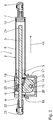
- a friction damper 1 has a housing 2 with a longitudinal axis 3 and a ram 4 displaceable along the longitudinal axis 3.
- the housing 2 is designed in several parts and has a cylinder housing section 5 and an associated damping housing section 6.
- the cylinder housing section 5 and the damping housing section 6 are arranged one behind the other along the longitudinal axis 3.
- the cylinder housing section 5 and the damping housing section 6 connected thereto form the common housing 2.
- the cylinder housing section 5 can be designed as a cylinder tube. In the plane perpendicular to the longitudinal axis 3, the cylinder housing section 5 can have a different cross-sectional shape, in particular a non-circular cross-sectional shape with a non-round inner contour.
- the housing 2 is closed at a the plunger 4 opposite end with a sealing plug 7.
- a first fastening element 8 is attached in the form of a ball head receptacle.
- the plunger 4 is arranged with a free end 21 within the housing 2.
- a pull-out protection in particular in the form of a disk, can be arranged in order to prevent the plunger 4 from being pulled out of the housing 2 inadvertently completely.
- a free end 21 opposite outer end 22 of the plunger 4 is disposed outside of the housing 2.
- a second fastening element 23 is arranged, which may be listed in particular identical to the first fastening element 8 as a ball head receptacle.
- the friction damper on the components whose relative movement is to be damped to each other are attached.
- the first fastening element is fastened to a furniture carcass and the second fastening element 23 is attached to a furniture flap.
- the cylinder housing section 5 is connected directly to the damping housing section 6 by means of an insertion plug 9.
- the insertion plug 9 is made in one piece with the damping housing section 6.
- the sealing plug 7 and the insertion plug 9 are held on the cylinder tube by radially inwardly projecting compression 10. Along the outer circumference, a plurality of, in particular six or eight, pressings 10 are provided on the cylinder tube.
- the sealing plug 7 and the insertion plug 9 are clearly defined relative to the longitudinal axis 3 both axially and radially on the cylinder housing.
- the damping housing section 6 is executed in a plane perpendicular to the longitudinal axis 3 out of round.
- the damping housing section 6 In an upper region of the damping housing section 6, which is traversed by the longitudinal axis 3, the damping housing section 6 has a substantially hourglass-shaped recess 11.
- the hourglass-shaped recess 11 has two frusto-conical recesses 12, which are conically tapered to one another and are connected to each other by a disc section 13.
- a cylindrical tilting pin 14 is provided in the damping housing section 6.
- the tilting pin 14 extends along a tilting axis 15, which is oriented perpendicular to the longitudinal axis 3 of the housing 2.
- the tilting axis 15 is oriented at a distance from the longitudinal axis 3.
- the tilting axis 15 and the longitudinal axis 3 are oriented perpendicular to each other.
- the tilting axis 15 and the longitudinal axis 3 do not intersect.
- the positional relationship of the tilting axis 15 and the longitudinal axis 3 in space is referred to as skewed.
- the insertion plug 9 has a continuous opening 16 through which the plunger 4 is guided displaced.
- the damping housing section 6 is designed in several parts and has two identical housing parts 17.
- the housing parts 17 are separable in a parting plane, which is oriented perpendicular to the tilting axis 15.
- the dividing plane has the longitudinal axis 3.
- the housing parts 17 have, for example, two connecting pins 18, which correspond to each other Connection openings 19 can be inserted.
- the two housing parts 17 can be plugged together to form the damping housing section 6.
- the housing 2 has a housing opening 20 through which the plunger 4 is guided into the housing 2.
- the housing opening 20 is arranged on the damping housing section 6, the opening 16 opposite.
- the housing opening 20 and the opening 16 are both arranged concentrically to the longitudinal axis 3.
- the friction damper 1 has a friction unit 24, which comprises two friction linings 25 and a friction lining carrier 26.
- the friction lining carrier 26 has a support plate 27.
- a tilting opening 28 is provided, with which the friction lining carrier 26 on the tilting pin 14 about the tilting axis 15 tiltable in the housing 2, in particular in the damping housing section 6, is arranged.
- a passage portion 29 is integrally formed, which has a passage opening 30.
- the passage section 29 is hollow. Through the passage opening 30 of the plunger 4 is passed.
- the passage opening 30 is executed in a plane perpendicular to the longitudinal axis 3 at least partially unsymmetrical.
- the passage opening 30 has a first passage opening section 31 and a second passage opening section 32, each having a section longitudinal axis 33 and 34, respectively.
- the first section longitudinal axis 33 and the second section longitudinal axis 34 are inclined relative to each other and have an angle of inclination n, which is about 10 ° according to the embodiment shown.
- the section longitudinal axes 33, 34 intersect at the point of intersection 35.
- the first passage opening section 31 extends as in FIG Fig. 9 shown, left above and right below the first section longitudinal axis 33 with respect to the intersection 35th
- the first passage opening section is designed as a semi-cylindrical recess along the first section longitudinal axis 33, wherein the first passage opening section 31 has two sections, which are executed separately and arranged mirror-symmetrically to the intersection 35.
- the sections of the second passage opening section 32 are mirror-symmetrical to the point of intersection 35 and separated from one another.
- a friction lining receptacle 36 are arranged in the first passage opening portion 31 in the two sections, in which the respective semi-cylindrical shell-shaped friction lining 25 is inserted.
- the two friction linings 25 are arranged on the friction lining carrier 26 Z-shaped.
- the through hole 30 has an asymmetrical cross section.
- the first passage opening section 31 or the second passage opening section 3 extends due to the inclined arrangement of the section longitudinal axes 33, 34, the cross-sectional area and / or the cross-sectional contour of the passage opening 30 along the longitudinal axis 3 is variable ,
- the friction lining carrier 26 may be made of two mirror-symmetrical friction lining carrier parts 37.
- the Reibbelagskulmaschinener 37 each have a connecting pin 38 and a connecting recess 39 which for engaging the friction lining carrier parts 37 to engage the friction lining carrier 26 in one another alternately.
- the function of the friction damper 1 based on Fig. 2 and 3 explained in more detail.
- the plunger 4 comes into contact with the friction linings 25.
- the friction lining carrier 26 is carried along by the plunger 4, ie pivoted about the tilting axis 15 into an extracting position.
- the amount of static friction which corresponds to a basic friction and has a value greater than 0N, is specifically adjustable in particular.
- a specific adjustability of the static friction value is made possible by the axial and / or radial prestressing with which the friction lining 25 is arranged in the friction lining carrier 26.
- the pull-out position of the friction lining carrier 26 is in Fig. 2 shown.
- the pull-out position of the friction lining carrier 26 means that the half-shell-shaped friction linings 25 abut in each case with their cylindrical inner surface on an outer surface of the plunger 4.
- the in Fig. 2 shown on the left Friction lining 25 presses from above on the plunger 4.
- the in Fig. 2 Friction lining 25 shown on the right pushes against the plunger 4 from below.
- the friction linings 25 are reliably pressed against the outside of the plunger 4.
- An axial displacement of the plunger 4 is frictionally damped by means of the friction linings 25.
- a frictional action, a pull-out friction, between the plunger 4 and the friction linings 25 acts.
- the friction lining carrier 26 is in the insertion position. In the insertion position a push-in friction is caused. According to the embodiment shown, the extension friction and the insertion friction differ from each other. In the embodiment shown, the insertion friction is substantially absent, since no friction lining is provided in the second passage opening section 32. In the first passage opening section 31, the friction linings 25 are in each case in contact with an outer, frontal outer edge from above and below on the plunger 4.
- the second passage opening section 32 is embodied in sections as a cylinder opening which has an inner diameter which is slightly larger than the outer diameter of the plunger 4. In the arrangement of the friction lining carrier 26 in the insertion position, the plunger 4 becomes substantially friction-free through the passage opening 30 guided.
- the essential difference of the friction damper 1a is that the housing 2a has no cylinder housing portion.
- the housing 2a exclusively includes the damper housing portion 6a.
- the plunger 4a is passed through the housing 2a and is exposed on both sides of the housing 2a.
- a pull-stop element 42 is provided, which is integrally formed according to the embodiment shown on the plunger 4a.
- the pull-stop element 42 is disc-shaped and has a diameter perpendicular to the longitudinal axis 3, which is greater than the diameter of the housing opening 20th
- the first fastening element 8a is arranged on the outside of the housing 2a, in particular on the damping housing section 6a.
- the first fastening element 8a is designed in the form of a receiving socket, which is in particular integrally formed on the housing 2a, in particular on the damping housing section 6a.
- the receiving socket is designed sleeve-shaped and can cooperate on a non-illustrated spigot on the furniture element 44 for a pivotal connection.
- a latching element may be provided on an inner side of the receiving nozzle in order to axially secure the receiving pin inserted into the receiving socket, in particular to latch it. An unwanted loosening of the receiving nozzle from the spigot is thereby prevented.
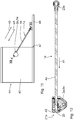
- the friction damper 1a in particular with the housing 2a, is pivotably articulated about a housing pivot axis 43 on the furniture element 44, in particular on a furniture carcass 45.
- a furniture flap 46 On the furniture body 45, a furniture flap 46 is pivotally articulated.
- the second fastening element 23a of the friction damper 1a is pivotally hinged to the furniture flap 46.
- the housing pivot axis 43 is oriented perpendicular to the longitudinal axis 3.
- the housing pivot axis 43 intersects the longitudinal axis 3.
- the function of the friction damper 1a according to the second embodiment will be explained in more detail.
- the furniture flap 46 is pivoted about the furniture element pivot axis 47 relative to the furniture body 45 for opening.
- the plunger 4a which is hinged to the second fastening element 23a on the furniture flap 46, displaced relative to the housing 2a along the extension direction 40.
- the housing 2a can pivot about the GeHouseschwenkachse 43. This ensures that the housing 2a follows the pivoting movement of the furniture flap 46. It is ensured that the friction damper 1a is hinged to the furniture element 44 such that the longitudinal axis 3 is oriented parallel to the extension direction 40 or the insertion direction 41.
- the inclination of the extension direction 40 or the insertion direction 41 depends on the pivot angle of the furniture flap 46 relative to the furniture body 45.
- Fig. 11 are the extension direction 40 and the insertion direction 41 for the pivot angle of the furniture flap of 90 ° shown opposite the furniture body 45. The smaller the pivot angle of the furniture flap 46, the lower the inclination of the extension direction 40 or the insertion direction 41 relative to the horizontal in Fig. 11 ,
- insertion direction 41 and the extension direction 40 are oriented horizontally.
- the plunger 4a In a closing movement of the furniture flap 46 relative to the furniture body 45, the plunger 4a is displaced along the insertion direction 41 relative to the housing 2a.
- the friction linings 25 are due to the static friction between the friction linings 25 and the plunger 4a with the Reibbelagsnov 26 about the tilting axis 15 in the counterclockwise direction in the in Fig. 14 shifted shown tilting position. In this position, the friction lining carrier 26 with the friction linings 25 causes a minimal and in particular no frictional effect.
- the function of the friction damper 1a is substantially identical to that of the friction damper 1 according to the first embodiment.
Landscapes
- Engineering & Computer Science (AREA)
- General Engineering & Computer Science (AREA)
- Mechanical Engineering (AREA)
- Vibration Prevention Devices (AREA)
- Vibration Dampers (AREA)
- Fluid-Damping Devices (AREA)
Priority Applications (3)
| Application Number | Priority Date | Filing Date | Title |
|---|---|---|---|
| EP18179745.7A EP3399207B1 (de) | 2016-09-14 | 2017-09-11 | Reibungsdämpfer |
| PL17190277T PL3296587T3 (pl) | 2016-09-14 | 2017-09-11 | Tłumik cierny |
| PL18179745T PL3399207T3 (pl) | 2016-09-14 | 2017-09-11 | Amortyzator cierny |
Applications Claiming Priority (1)
| Application Number | Priority Date | Filing Date | Title |
|---|---|---|---|
| DE102016217484 | 2016-09-14 |
Related Child Applications (2)
| Application Number | Title | Priority Date | Filing Date |
|---|---|---|---|
| EP18179745.7A Division EP3399207B1 (de) | 2016-09-14 | 2017-09-11 | Reibungsdämpfer |
| EP18179745.7A Division-Into EP3399207B1 (de) | 2016-09-14 | 2017-09-11 | Reibungsdämpfer |
Publications (2)
| Publication Number | Publication Date |
|---|---|
| EP3296587A1 EP3296587A1 (de) | 2018-03-21 |
| EP3296587B1 true EP3296587B1 (de) | 2019-01-02 |
Family
ID=59856393
Family Applications (2)
| Application Number | Title | Priority Date | Filing Date |
|---|---|---|---|
| EP17190277.8A Active EP3296587B1 (de) | 2016-09-14 | 2017-09-11 | Reibungsdämpfer |
| EP18179745.7A Active EP3399207B1 (de) | 2016-09-14 | 2017-09-11 | Reibungsdämpfer |
Family Applications After (1)
| Application Number | Title | Priority Date | Filing Date |
|---|---|---|---|
| EP18179745.7A Active EP3399207B1 (de) | 2016-09-14 | 2017-09-11 | Reibungsdämpfer |
Country Status (10)
| Country | Link |
|---|---|
| US (1) | US10436273B2 (pl) |
| EP (2) | EP3296587B1 (pl) |
| JP (1) | JP2018044674A (pl) |
| KR (1) | KR102440755B1 (pl) |
| CN (1) | CN107816503B (pl) |
| DE (1) | DE102017215933A1 (pl) |
| ES (2) | ES2815898T3 (pl) |
| PL (2) | PL3296587T3 (pl) |
| RU (1) | RU2684237C9 (pl) |
| TR (1) | TR201904420T4 (pl) |
Families Citing this family (4)
| Publication number | Priority date | Publication date | Assignee | Title |
|---|---|---|---|---|
| JP6299558B2 (ja) * | 2014-10-28 | 2018-03-28 | アイシン精機株式会社 | 車体補強装置 |
| GB2577682B (en) * | 2018-09-28 | 2021-10-20 | Owen Mumford Ltd | Auto-injector |
| DE102020202348A1 (de) | 2020-02-24 | 2021-08-26 | Suspa Gmbh | Reibungsdämpfer |
| DE102022209864A1 (de) * | 2022-09-20 | 2024-03-21 | Suspa Gmbh | Reibungsdämpfer |
Family Cites Families (18)
| Publication number | Priority date | Publication date | Assignee | Title |
|---|---|---|---|---|
| DE1085725B (de) | 1958-08-28 | 1960-07-21 | Peka Fahrzeugbau K G | Reibungsstossdaempfer |
| DE2117704A1 (de) * | 1971-04-10 | 1972-10-19 | Philips Patentverwaltung | Mechanische Stoßdämpfereinrichtung |
| SU894261A2 (ru) * | 1980-03-10 | 1981-12-30 | Брянский Институт Транспортного Машиностроения | Демпфер переменного трени |
| DD159803A2 (de) * | 1981-06-18 | 1983-04-06 | Erich Barth | Reibungsdaempfer fuer schwingungsgedaempfte maschinen und geraete,insbesondere trommelwaschmaschinen |
| DD232408A3 (de) * | 1983-02-02 | 1986-01-29 | Schwarzenberg Waschgeraete | Reibungsdaempfer fuer schwingungsgedaempfte maschinen und geraete, insbesondere trommelwaschmaschinen |
| DE3616373A1 (de) * | 1986-05-15 | 1987-11-19 | Miele & Cie | Reibungsdaempfer |
| DE19615010A1 (de) * | 1996-04-16 | 1997-10-23 | Suspa Compart Ag | Reibungsdämpfer, insbesondere für Waschmaschinen mit Schleudergang |
| DE20109958U1 (de) * | 2001-06-15 | 2001-08-16 | Julius Blum Ges.m.b.H., Höchst | Dämpfer insbesondere für Möbel |
| DE10358204A1 (de) * | 2003-12-12 | 2005-07-07 | Contitech Vibration Control Gmbh | Reibdämpfer |
| DE10360784B4 (de) | 2003-12-23 | 2012-02-09 | Audi Ag | Vorrichtung zum Ausrücken und Einrücken der Kupplung eines Kraftfahrzeuges |
| DE10360721A1 (de) * | 2003-12-24 | 2005-07-21 | Moll System- und Funktionsmöbel GmbH | Bremsvorrichtung für Arbeitstische |
| ES2300909T3 (es) * | 2004-09-15 | 2008-06-16 | Suspa Holding Gmbh | Amortiguador. |
| CN201606444U (zh) * | 2010-02-10 | 2010-10-13 | 济南大学 | 一种摩擦-粘滞综合作用的阻尼器 |
| CN103925321B (zh) * | 2013-01-15 | 2017-05-31 | 青岛海尔洗衣机有限公司 | 一种变阻尼减震器及装有该减震器的洗衣机 |
| DE102013109196B4 (de) | 2013-08-26 | 2023-03-02 | Miele & Cie. Kg | Reibungsdämpfer, insbesondere für eine Trommelwaschmaschine |
| JP2015112959A (ja) | 2013-12-10 | 2015-06-22 | 株式会社ショーワ | 操舵装置 |
| CN204163514U (zh) * | 2014-10-17 | 2015-02-18 | 漳州职业技术学院 | 窗户锁紧装置 |
| CN105351419B (zh) * | 2015-11-27 | 2017-07-04 | 北京工业大学 | 具有复阻尼特征的板式向心摩擦阻尼器 |
-
2017
- 2017-08-31 RU RU2017130852A patent/RU2684237C9/ru active
- 2017-09-11 EP EP17190277.8A patent/EP3296587B1/de active Active
- 2017-09-11 PL PL17190277T patent/PL3296587T3/pl unknown
- 2017-09-11 EP EP18179745.7A patent/EP3399207B1/de active Active
- 2017-09-11 TR TR2019/04420T patent/TR201904420T4/tr unknown
- 2017-09-11 ES ES18179745T patent/ES2815898T3/es active Active
- 2017-09-11 DE DE102017215933.2A patent/DE102017215933A1/de not_active Withdrawn
- 2017-09-11 ES ES17190277T patent/ES2715975T3/es active Active
- 2017-09-11 PL PL18179745T patent/PL3399207T3/pl unknown
- 2017-09-13 US US15/703,071 patent/US10436273B2/en active Active
- 2017-09-13 JP JP2017175545A patent/JP2018044674A/ja active Pending
- 2017-09-14 CN CN201710828922.5A patent/CN107816503B/zh active Active
- 2017-09-14 KR KR1020170117833A patent/KR102440755B1/ko active Active
Non-Patent Citations (1)
| Title |
|---|
| None * |
Also Published As
| Publication number | Publication date |
|---|---|
| RU2684237C2 (ru) | 2019-04-04 |
| PL3296587T3 (pl) | 2019-06-28 |
| JP2018044674A (ja) | 2018-03-22 |
| KR102440755B1 (ko) | 2022-09-05 |
| BR102017019575A2 (pt) | 2018-05-02 |
| RU2017130852A3 (pl) | 2019-02-28 |
| EP3296587A1 (de) | 2018-03-21 |
| US20180073589A1 (en) | 2018-03-15 |
| KR20180030396A (ko) | 2018-03-22 |
| ES2815898T3 (es) | 2021-03-31 |
| CN107816503A (zh) | 2018-03-20 |
| CN107816503B (zh) | 2021-09-28 |
| DE102017215933A1 (de) | 2018-03-15 |
| US10436273B2 (en) | 2019-10-08 |
| RU2017130852A (ru) | 2019-02-28 |
| TR201904420T4 (tr) | 2019-05-21 |
| EP3399207A1 (de) | 2018-11-07 |
| RU2684237C9 (ru) | 2019-07-09 |
| ES2715975T3 (es) | 2019-06-07 |
| EP3399207B1 (de) | 2020-06-17 |
| PL3399207T3 (pl) | 2020-12-28 |
Similar Documents
| Publication | Publication Date | Title |
|---|---|---|
| EP3051175B1 (de) | Dämpferanordnung, insbesondere für eine klappe eines fahrzeugs | |
| DE19642806C1 (de) | Pneumatischer Bewegungsdämpfer | |
| EP2174571B1 (de) | Öffnungsvorrichtung für eine Ausziehführung und Rastmechanismus | |
| EP3296587B1 (de) | Reibungsdämpfer | |
| DE112014004355T9 (de) | Rohrförmige Schwingungsdämpfungsvorrichtung | |
| EP3746665B1 (de) | Möbelbeschlag | |
| DE19717937A1 (de) | Brems- und Dämpfungselement für bewegliche Möbelteile | |
| EP2949961B1 (de) | Bewegungsdämpfungseinheit und federeinheit mit einer derartigen bewegungsdämpfungseinheit | |
| EP3044071B1 (de) | Anordnung mit zumindest einem federkörper und zumindest einem separat ausgebildeten arretierteil | |
| WO2016177706A1 (de) | Möbelscharnier mit einem dämpfer und einer feder | |
| WO2020236100A1 (de) | Möbelbeschlag | |
| AT514666B1 (de) | Führungsvorrichtung für bewegbare Möbelteile | |
| DE112019001567T5 (de) | Dämpfer | |
| EP1674779A1 (de) | Verbindungseinrichtung | |
| DE10121977B4 (de) | Möbelbeschlag mit Brems- und Dämpfungsvorrichtung | |
| DE602006000591T2 (de) | Gasfederstütze | |
| EP1840309A1 (de) | Klappenhalter für eine Möbelklappe | |
| EP2251514B1 (de) | Deckelsteller | |
| EP2244926B1 (de) | Lenksäule für ein kraftfahrzeug, mit einer lenkspindel und einer feststelleinrichtung | |
| EP3652402B1 (de) | Möbeldämpfer | |
| DE102012221645B4 (de) | Federsystem für eine schwenkbare, in einer Schließlage verriegelbare Klappe eines Kraftfahrzeugs | |
| DE102019102253A1 (de) | Antriebsvorrichtung für ein Verschlusselement eines Kraftfahrzeugs | |
| DE102020202348A1 (de) | Reibungsdämpfer | |
| AT403498B (de) | Fixiereinrichtung für brandschutztüren | |
| DE102015200670B3 (de) | Federanordnung mit Hysteres und Übergas-Eigenschaft |
Legal Events
| Date | Code | Title | Description |
|---|---|---|---|
| PUAI | Public reference made under article 153(3) epc to a published international application that has entered the european phase |
Free format text: ORIGINAL CODE: 0009012 |
|
| STAA | Information on the status of an ep patent application or granted ep patent |
Free format text: STATUS: THE APPLICATION HAS BEEN PUBLISHED |
|
| AK | Designated contracting states |
Kind code of ref document: A1 Designated state(s): AL AT BE BG CH CY CZ DE DK EE ES FI FR GB GR HR HU IE IS IT LI LT LU LV MC MK MT NL NO PL PT RO RS SE SI SK SM TR |
|
| AX | Request for extension of the european patent |
Extension state: BA ME |
|
| STAA | Information on the status of an ep patent application or granted ep patent |
Free format text: STATUS: REQUEST FOR EXAMINATION WAS MADE |
|
| GRAP | Despatch of communication of intention to grant a patent |
Free format text: ORIGINAL CODE: EPIDOSNIGR1 |
|
| STAA | Information on the status of an ep patent application or granted ep patent |
Free format text: STATUS: GRANT OF PATENT IS INTENDED |
|
| 17P | Request for examination filed |
Effective date: 20180620 |
|
| RBV | Designated contracting states (corrected) |
Designated state(s): AL AT BE BG CH CY CZ DE DK EE ES FI FR GB GR HR HU IE IS IT LI LT LU LV MC MK MT NL NO PL PT RO RS SE SI SK SM TR |
|
| INTG | Intention to grant announced |
Effective date: 20180731 |
|
| GRAS | Grant fee paid |
Free format text: ORIGINAL CODE: EPIDOSNIGR3 |
|
| GRAA | (expected) grant |
Free format text: ORIGINAL CODE: 0009210 |
|
| STAA | Information on the status of an ep patent application or granted ep patent |
Free format text: STATUS: THE PATENT HAS BEEN GRANTED |
|
| AK | Designated contracting states |
Kind code of ref document: B1 Designated state(s): AL AT BE BG CH CY CZ DE DK EE ES FI FR GB GR HR HU IE IS IT LI LT LU LV MC MK MT NL NO PL PT RO RS SE SI SK SM TR |
|
| REG | Reference to a national code |
Ref country code: GB Ref legal event code: FG4D Free format text: NOT ENGLISH |
|
| REG | Reference to a national code |
Ref country code: CH Ref legal event code: EP Ref country code: AT Ref legal event code: REF Ref document number: 1084773 Country of ref document: AT Kind code of ref document: T Effective date: 20190115 |
|
| REG | Reference to a national code |
Ref country code: DE Ref legal event code: R096 Ref document number: 502017000604 Country of ref document: DE |
|
| REG | Reference to a national code |
Ref country code: IE Ref legal event code: FG4D Free format text: LANGUAGE OF EP DOCUMENT: GERMAN |
|
| REG | Reference to a national code |
Ref country code: NL Ref legal event code: MP Effective date: 20190102 |
|
| REG | Reference to a national code |
Ref country code: LT Ref legal event code: MG4D |
|
| REG | Reference to a national code |
Ref country code: SK Ref legal event code: T3 Ref document number: E 30296 Country of ref document: SK |
|
| REG | Reference to a national code |
Ref country code: ES Ref legal event code: FG2A Ref document number: 2715975 Country of ref document: ES Kind code of ref document: T3 Effective date: 20190607 |
|
| PG25 | Lapsed in a contracting state [announced via postgrant information from national office to epo] |
Ref country code: NL Free format text: LAPSE BECAUSE OF FAILURE TO SUBMIT A TRANSLATION OF THE DESCRIPTION OR TO PAY THE FEE WITHIN THE PRESCRIBED TIME-LIMIT Effective date: 20190102 |
|
| PG25 | Lapsed in a contracting state [announced via postgrant information from national office to epo] |
Ref country code: LT Free format text: LAPSE BECAUSE OF FAILURE TO SUBMIT A TRANSLATION OF THE DESCRIPTION OR TO PAY THE FEE WITHIN THE PRESCRIBED TIME-LIMIT Effective date: 20190102 Ref country code: SE Free format text: LAPSE BECAUSE OF FAILURE TO SUBMIT A TRANSLATION OF THE DESCRIPTION OR TO PAY THE FEE WITHIN THE PRESCRIBED TIME-LIMIT Effective date: 20190102 Ref country code: NO Free format text: LAPSE BECAUSE OF FAILURE TO SUBMIT A TRANSLATION OF THE DESCRIPTION OR TO PAY THE FEE WITHIN THE PRESCRIBED TIME-LIMIT Effective date: 20190402 Ref country code: FI Free format text: LAPSE BECAUSE OF FAILURE TO SUBMIT A TRANSLATION OF THE DESCRIPTION OR TO PAY THE FEE WITHIN THE PRESCRIBED TIME-LIMIT Effective date: 20190102 Ref country code: PT Free format text: LAPSE BECAUSE OF FAILURE TO SUBMIT A TRANSLATION OF THE DESCRIPTION OR TO PAY THE FEE WITHIN THE PRESCRIBED TIME-LIMIT Effective date: 20190502 |
|
| PG25 | Lapsed in a contracting state [announced via postgrant information from national office to epo] |
Ref country code: RS Free format text: LAPSE BECAUSE OF FAILURE TO SUBMIT A TRANSLATION OF THE DESCRIPTION OR TO PAY THE FEE WITHIN THE PRESCRIBED TIME-LIMIT Effective date: 20190102 Ref country code: BG Free format text: LAPSE BECAUSE OF FAILURE TO SUBMIT A TRANSLATION OF THE DESCRIPTION OR TO PAY THE FEE WITHIN THE PRESCRIBED TIME-LIMIT Effective date: 20190402 Ref country code: IS Free format text: LAPSE BECAUSE OF FAILURE TO SUBMIT A TRANSLATION OF THE DESCRIPTION OR TO PAY THE FEE WITHIN THE PRESCRIBED TIME-LIMIT Effective date: 20190502 Ref country code: LV Free format text: LAPSE BECAUSE OF FAILURE TO SUBMIT A TRANSLATION OF THE DESCRIPTION OR TO PAY THE FEE WITHIN THE PRESCRIBED TIME-LIMIT Effective date: 20190102 Ref country code: GR Free format text: LAPSE BECAUSE OF FAILURE TO SUBMIT A TRANSLATION OF THE DESCRIPTION OR TO PAY THE FEE WITHIN THE PRESCRIBED TIME-LIMIT Effective date: 20190403 Ref country code: HR Free format text: LAPSE BECAUSE OF FAILURE TO SUBMIT A TRANSLATION OF THE DESCRIPTION OR TO PAY THE FEE WITHIN THE PRESCRIBED TIME-LIMIT Effective date: 20190102 |
|
| REG | Reference to a national code |
Ref country code: DE Ref legal event code: R097 Ref document number: 502017000604 Country of ref document: DE |
|
| PG25 | Lapsed in a contracting state [announced via postgrant information from national office to epo] |
Ref country code: EE Free format text: LAPSE BECAUSE OF FAILURE TO SUBMIT A TRANSLATION OF THE DESCRIPTION OR TO PAY THE FEE WITHIN THE PRESCRIBED TIME-LIMIT Effective date: 20190102 Ref country code: DK Free format text: LAPSE BECAUSE OF FAILURE TO SUBMIT A TRANSLATION OF THE DESCRIPTION OR TO PAY THE FEE WITHIN THE PRESCRIBED TIME-LIMIT Effective date: 20190102 Ref country code: AL Free format text: LAPSE BECAUSE OF FAILURE TO SUBMIT A TRANSLATION OF THE DESCRIPTION OR TO PAY THE FEE WITHIN THE PRESCRIBED TIME-LIMIT Effective date: 20190102 Ref country code: RO Free format text: LAPSE BECAUSE OF FAILURE TO SUBMIT A TRANSLATION OF THE DESCRIPTION OR TO PAY THE FEE WITHIN THE PRESCRIBED TIME-LIMIT Effective date: 20190102 Ref country code: CZ Free format text: LAPSE BECAUSE OF FAILURE TO SUBMIT A TRANSLATION OF THE DESCRIPTION OR TO PAY THE FEE WITHIN THE PRESCRIBED TIME-LIMIT Effective date: 20190102 |
|
| PLBE | No opposition filed within time limit |
Free format text: ORIGINAL CODE: 0009261 |
|
| STAA | Information on the status of an ep patent application or granted ep patent |
Free format text: STATUS: NO OPPOSITION FILED WITHIN TIME LIMIT |
|
| PG25 | Lapsed in a contracting state [announced via postgrant information from national office to epo] |
Ref country code: SM Free format text: LAPSE BECAUSE OF FAILURE TO SUBMIT A TRANSLATION OF THE DESCRIPTION OR TO PAY THE FEE WITHIN THE PRESCRIBED TIME-LIMIT Effective date: 20190102 |
|
| 26N | No opposition filed |
Effective date: 20191003 |
|
| PG25 | Lapsed in a contracting state [announced via postgrant information from national office to epo] |
Ref country code: SI Free format text: LAPSE BECAUSE OF FAILURE TO SUBMIT A TRANSLATION OF THE DESCRIPTION OR TO PAY THE FEE WITHIN THE PRESCRIBED TIME-LIMIT Effective date: 20190102 |
|
| PG25 | Lapsed in a contracting state [announced via postgrant information from national office to epo] |
Ref country code: MC Free format text: LAPSE BECAUSE OF FAILURE TO SUBMIT A TRANSLATION OF THE DESCRIPTION OR TO PAY THE FEE WITHIN THE PRESCRIBED TIME-LIMIT Effective date: 20190102 |
|
| PG25 | Lapsed in a contracting state [announced via postgrant information from national office to epo] |
Ref country code: IE Free format text: LAPSE BECAUSE OF NON-PAYMENT OF DUE FEES Effective date: 20190911 Ref country code: LU Free format text: LAPSE BECAUSE OF NON-PAYMENT OF DUE FEES Effective date: 20190911 |
|
| REG | Reference to a national code |
Ref country code: BE Ref legal event code: MM Effective date: 20190930 |
|
| PG25 | Lapsed in a contracting state [announced via postgrant information from national office to epo] |
Ref country code: BE Free format text: LAPSE BECAUSE OF NON-PAYMENT OF DUE FEES Effective date: 20190930 |
|
| REG | Reference to a national code |
Ref country code: CH Ref legal event code: PL |
|
| PG25 | Lapsed in a contracting state [announced via postgrant information from national office to epo] |
Ref country code: CY Free format text: LAPSE BECAUSE OF FAILURE TO SUBMIT A TRANSLATION OF THE DESCRIPTION OR TO PAY THE FEE WITHIN THE PRESCRIBED TIME-LIMIT Effective date: 20190102 |
|
| PG25 | Lapsed in a contracting state [announced via postgrant information from national office to epo] |
Ref country code: HU Free format text: LAPSE BECAUSE OF FAILURE TO SUBMIT A TRANSLATION OF THE DESCRIPTION OR TO PAY THE FEE WITHIN THE PRESCRIBED TIME-LIMIT; INVALID AB INITIO Effective date: 20170911 Ref country code: MT Free format text: LAPSE BECAUSE OF FAILURE TO SUBMIT A TRANSLATION OF THE DESCRIPTION OR TO PAY THE FEE WITHIN THE PRESCRIBED TIME-LIMIT Effective date: 20190102 |
|
| PG25 | Lapsed in a contracting state [announced via postgrant information from national office to epo] |
Ref country code: LI Free format text: LAPSE BECAUSE OF NON-PAYMENT OF DUE FEES Effective date: 20200930 Ref country code: CH Free format text: LAPSE BECAUSE OF NON-PAYMENT OF DUE FEES Effective date: 20200930 |
|
| GBPC | Gb: european patent ceased through non-payment of renewal fee |
Effective date: 20210911 |
|
| PG25 | Lapsed in a contracting state [announced via postgrant information from national office to epo] |
Ref country code: MK Free format text: LAPSE BECAUSE OF FAILURE TO SUBMIT A TRANSLATION OF THE DESCRIPTION OR TO PAY THE FEE WITHIN THE PRESCRIBED TIME-LIMIT Effective date: 20190102 |
|
| PG25 | Lapsed in a contracting state [announced via postgrant information from national office to epo] |
Ref country code: GB Free format text: LAPSE BECAUSE OF NON-PAYMENT OF DUE FEES Effective date: 20210911 |
|
| P01 | Opt-out of the competence of the unified patent court (upc) registered |
Effective date: 20230517 |
|
| REG | Reference to a national code |
Ref country code: AT Ref legal event code: MM01 Ref document number: 1084773 Country of ref document: AT Kind code of ref document: T Effective date: 20220911 |
|
| PG25 | Lapsed in a contracting state [announced via postgrant information from national office to epo] |
Ref country code: AT Free format text: LAPSE BECAUSE OF NON-PAYMENT OF DUE FEES Effective date: 20220911 |
|
| PGFP | Annual fee paid to national office [announced via postgrant information from national office to epo] |
Ref country code: TR Payment date: 20250908 Year of fee payment: 9 Ref country code: PL Payment date: 20250811 Year of fee payment: 9 |
|
| PGFP | Annual fee paid to national office [announced via postgrant information from national office to epo] |
Ref country code: FR Payment date: 20250925 Year of fee payment: 9 |
|
| PGFP | Annual fee paid to national office [announced via postgrant information from national office to epo] |
Ref country code: SK Payment date: 20250908 Year of fee payment: 9 |
|
| PGFP | Annual fee paid to national office [announced via postgrant information from national office to epo] |
Ref country code: DE Payment date: 20251121 Year of fee payment: 9 |
|
| PGFP | Annual fee paid to national office [announced via postgrant information from national office to epo] |
Ref country code: IT Payment date: 20250930 Year of fee payment: 9 |
|
| PGFP | Annual fee paid to national office [announced via postgrant information from national office to epo] |
Ref country code: ES Payment date: 20251020 Year of fee payment: 9 |