EP3296159B1 - Power supply system - Google Patents
Power supply system Download PDFInfo
- Publication number
- EP3296159B1 EP3296159B1 EP15891820.1A EP15891820A EP3296159B1 EP 3296159 B1 EP3296159 B1 EP 3296159B1 EP 15891820 A EP15891820 A EP 15891820A EP 3296159 B1 EP3296159 B1 EP 3296159B1
- Authority
- EP
- European Patent Office
- Prior art keywords
- lead acid
- acid battery
- battery
- lithium ion
- ion secondary
- Prior art date
- Legal status (The legal status is an assumption and is not a legal conclusion. Google has not performed a legal analysis and makes no representation as to the accuracy of the status listed.)
- Active
Links
Images


Classifications
-
- B—PERFORMING OPERATIONS; TRANSPORTING
- B60—VEHICLES IN GENERAL
- B60L—PROPULSION OF ELECTRICALLY-PROPELLED VEHICLES; SUPPLYING ELECTRIC POWER FOR AUXILIARY EQUIPMENT OF ELECTRICALLY-PROPELLED VEHICLES; ELECTRODYNAMIC BRAKE SYSTEMS FOR VEHICLES IN GENERAL; MAGNETIC SUSPENSION OR LEVITATION FOR VEHICLES; MONITORING OPERATING VARIABLES OF ELECTRICALLY-PROPELLED VEHICLES; ELECTRIC SAFETY DEVICES FOR ELECTRICALLY-PROPELLED VEHICLES
- B60L50/00—Electric propulsion with power supplied within the vehicle
- B60L50/50—Electric propulsion with power supplied within the vehicle using propulsion power supplied by batteries or fuel cells
- B60L50/60—Electric propulsion with power supplied within the vehicle using propulsion power supplied by batteries or fuel cells using power supplied by batteries
- B60L50/64—Constructional details of batteries specially adapted for electric vehicles
-
- B—PERFORMING OPERATIONS; TRANSPORTING
- B60—VEHICLES IN GENERAL
- B60L—PROPULSION OF ELECTRICALLY-PROPELLED VEHICLES; SUPPLYING ELECTRIC POWER FOR AUXILIARY EQUIPMENT OF ELECTRICALLY-PROPELLED VEHICLES; ELECTRODYNAMIC BRAKE SYSTEMS FOR VEHICLES IN GENERAL; MAGNETIC SUSPENSION OR LEVITATION FOR VEHICLES; MONITORING OPERATING VARIABLES OF ELECTRICALLY-PROPELLED VEHICLES; ELECTRIC SAFETY DEVICES FOR ELECTRICALLY-PROPELLED VEHICLES
- B60L50/00—Electric propulsion with power supplied within the vehicle
- B60L50/10—Electric propulsion with power supplied within the vehicle using propulsion power supplied by engine-driven generators, e.g. generators driven by combustion engines
- B60L50/16—Electric propulsion with power supplied within the vehicle using propulsion power supplied by engine-driven generators, e.g. generators driven by combustion engines with provision for separate direct mechanical propulsion
-
- B—PERFORMING OPERATIONS; TRANSPORTING
- B60—VEHICLES IN GENERAL
- B60L—PROPULSION OF ELECTRICALLY-PROPELLED VEHICLES; SUPPLYING ELECTRIC POWER FOR AUXILIARY EQUIPMENT OF ELECTRICALLY-PROPELLED VEHICLES; ELECTRODYNAMIC BRAKE SYSTEMS FOR VEHICLES IN GENERAL; MAGNETIC SUSPENSION OR LEVITATION FOR VEHICLES; MONITORING OPERATING VARIABLES OF ELECTRICALLY-PROPELLED VEHICLES; ELECTRIC SAFETY DEVICES FOR ELECTRICALLY-PROPELLED VEHICLES
- B60L50/00—Electric propulsion with power supplied within the vehicle
- B60L50/50—Electric propulsion with power supplied within the vehicle using propulsion power supplied by batteries or fuel cells
-
- B—PERFORMING OPERATIONS; TRANSPORTING
- B60—VEHICLES IN GENERAL
- B60L—PROPULSION OF ELECTRICALLY-PROPELLED VEHICLES; SUPPLYING ELECTRIC POWER FOR AUXILIARY EQUIPMENT OF ELECTRICALLY-PROPELLED VEHICLES; ELECTRODYNAMIC BRAKE SYSTEMS FOR VEHICLES IN GENERAL; MAGNETIC SUSPENSION OR LEVITATION FOR VEHICLES; MONITORING OPERATING VARIABLES OF ELECTRICALLY-PROPELLED VEHICLES; ELECTRIC SAFETY DEVICES FOR ELECTRICALLY-PROPELLED VEHICLES
- B60L7/00—Electrodynamic brake systems for vehicles in general
- B60L7/10—Dynamic electric regenerative braking
-
- B—PERFORMING OPERATIONS; TRANSPORTING
- B60—VEHICLES IN GENERAL
- B60R—VEHICLES, VEHICLE FITTINGS, OR VEHICLE PARTS, NOT OTHERWISE PROVIDED FOR
- B60R16/00—Electric or fluid circuits specially adapted for vehicles and not otherwise provided for; Arrangement of elements of electric or fluid circuits specially adapted for vehicles and not otherwise provided for
- B60R16/02—Electric or fluid circuits specially adapted for vehicles and not otherwise provided for; Arrangement of elements of electric or fluid circuits specially adapted for vehicles and not otherwise provided for electric constitutive elements
- B60R16/023—Electric or fluid circuits specially adapted for vehicles and not otherwise provided for; Arrangement of elements of electric or fluid circuits specially adapted for vehicles and not otherwise provided for electric constitutive elements for transmission of signals between vehicle parts or subsystems
-
- B—PERFORMING OPERATIONS; TRANSPORTING
- B60—VEHICLES IN GENERAL
- B60R—VEHICLES, VEHICLE FITTINGS, OR VEHICLE PARTS, NOT OTHERWISE PROVIDED FOR
- B60R16/00—Electric or fluid circuits specially adapted for vehicles and not otherwise provided for; Arrangement of elements of electric or fluid circuits specially adapted for vehicles and not otherwise provided for
- B60R16/02—Electric or fluid circuits specially adapted for vehicles and not otherwise provided for; Arrangement of elements of electric or fluid circuits specially adapted for vehicles and not otherwise provided for electric constitutive elements
- B60R16/03—Electric or fluid circuits specially adapted for vehicles and not otherwise provided for; Arrangement of elements of electric or fluid circuits specially adapted for vehicles and not otherwise provided for electric constitutive elements for supply of electrical power to vehicle subsystems or for
- B60R16/0307—Electric or fluid circuits specially adapted for vehicles and not otherwise provided for; Arrangement of elements of electric or fluid circuits specially adapted for vehicles and not otherwise provided for electric constitutive elements for supply of electrical power to vehicle subsystems or for using generators driven by a machine different from the vehicle motor
-
- B—PERFORMING OPERATIONS; TRANSPORTING
- B60—VEHICLES IN GENERAL
- B60R—VEHICLES, VEHICLE FITTINGS, OR VEHICLE PARTS, NOT OTHERWISE PROVIDED FOR
- B60R16/00—Electric or fluid circuits specially adapted for vehicles and not otherwise provided for; Arrangement of elements of electric or fluid circuits specially adapted for vehicles and not otherwise provided for
- B60R16/02—Electric or fluid circuits specially adapted for vehicles and not otherwise provided for; Arrangement of elements of electric or fluid circuits specially adapted for vehicles and not otherwise provided for electric constitutive elements
- B60R16/03—Electric or fluid circuits specially adapted for vehicles and not otherwise provided for; Arrangement of elements of electric or fluid circuits specially adapted for vehicles and not otherwise provided for electric constitutive elements for supply of electrical power to vehicle subsystems or for
- B60R16/033—Electric or fluid circuits specially adapted for vehicles and not otherwise provided for; Arrangement of elements of electric or fluid circuits specially adapted for vehicles and not otherwise provided for electric constitutive elements for supply of electrical power to vehicle subsystems or for characterised by the use of electrical cells or batteries
-
- F—MECHANICAL ENGINEERING; LIGHTING; HEATING; WEAPONS; BLASTING
- F02—COMBUSTION ENGINES; HOT-GAS OR COMBUSTION-PRODUCT ENGINE PLANTS
- F02N—STARTING OF COMBUSTION ENGINES; STARTING AIDS FOR SUCH ENGINES, NOT OTHERWISE PROVIDED FOR
- F02N11/00—Starting of engines by means of electric motors
- F02N11/08—Circuits or control means specially adapted for starting of engines
- F02N11/0814—Circuits or control means specially adapted for starting of engines comprising means for controlling automatic idle-start-stop
-
- F—MECHANICAL ENGINEERING; LIGHTING; HEATING; WEAPONS; BLASTING
- F02—COMBUSTION ENGINES; HOT-GAS OR COMBUSTION-PRODUCT ENGINE PLANTS
- F02N—STARTING OF COMBUSTION ENGINES; STARTING AIDS FOR SUCH ENGINES, NOT OTHERWISE PROVIDED FOR
- F02N11/00—Starting of engines by means of electric motors
- F02N11/08—Circuits or control means specially adapted for starting of engines
- F02N11/0862—Circuits or control means specially adapted for starting of engines characterised by the electrical power supply means, e.g. battery
- F02N11/0866—Circuits or control means specially adapted for starting of engines characterised by the electrical power supply means, e.g. battery comprising several power sources, e.g. battery and capacitor or two batteries
-
- H—ELECTRICITY
- H02—GENERATION; CONVERSION OR DISTRIBUTION OF ELECTRIC POWER
- H02J—CIRCUIT ARRANGEMENTS OR SYSTEMS FOR SUPPLYING OR DISTRIBUTING ELECTRIC POWER; SYSTEMS FOR STORING ELECTRIC ENERGY
- H02J7/00—Circuit arrangements for charging or depolarising batteries or for supplying loads from batteries
- H02J7/14—Circuit arrangements for charging or depolarising batteries or for supplying loads from batteries for charging batteries from dynamo-electric generators driven at varying speed, e.g. on vehicle
-
- F—MECHANICAL ENGINEERING; LIGHTING; HEATING; WEAPONS; BLASTING
- F02—COMBUSTION ENGINES; HOT-GAS OR COMBUSTION-PRODUCT ENGINE PLANTS
- F02N—STARTING OF COMBUSTION ENGINES; STARTING AIDS FOR SUCH ENGINES, NOT OTHERWISE PROVIDED FOR
- F02N2200/00—Parameters used for control of starting apparatus
- F02N2200/06—Parameters used for control of starting apparatus said parameters being related to the power supply or driving circuits for the starter
- F02N2200/063—Battery voltage
-
- F—MECHANICAL ENGINEERING; LIGHTING; HEATING; WEAPONS; BLASTING
- F02—COMBUSTION ENGINES; HOT-GAS OR COMBUSTION-PRODUCT ENGINE PLANTS
- F02N—STARTING OF COMBUSTION ENGINES; STARTING AIDS FOR SUCH ENGINES, NOT OTHERWISE PROVIDED FOR
- F02N2250/00—Problems related to engine starting or engine's starting apparatus
- F02N2250/02—Battery voltage drop at start, e.g. drops causing ECU reset
-
- Y—GENERAL TAGGING OF NEW TECHNOLOGICAL DEVELOPMENTS; GENERAL TAGGING OF CROSS-SECTIONAL TECHNOLOGIES SPANNING OVER SEVERAL SECTIONS OF THE IPC; TECHNICAL SUBJECTS COVERED BY FORMER USPC CROSS-REFERENCE ART COLLECTIONS [XRACs] AND DIGESTS
- Y02—TECHNOLOGIES OR APPLICATIONS FOR MITIGATION OR ADAPTATION AGAINST CLIMATE CHANGE
- Y02T—CLIMATE CHANGE MITIGATION TECHNOLOGIES RELATED TO TRANSPORTATION
- Y02T10/00—Road transport of goods or passengers
- Y02T10/10—Internal combustion engine [ICE] based vehicles
- Y02T10/40—Engine management systems
-
- Y—GENERAL TAGGING OF NEW TECHNOLOGICAL DEVELOPMENTS; GENERAL TAGGING OF CROSS-SECTIONAL TECHNOLOGIES SPANNING OVER SEVERAL SECTIONS OF THE IPC; TECHNICAL SUBJECTS COVERED BY FORMER USPC CROSS-REFERENCE ART COLLECTIONS [XRACs] AND DIGESTS
- Y02—TECHNOLOGIES OR APPLICATIONS FOR MITIGATION OR ADAPTATION AGAINST CLIMATE CHANGE
- Y02T—CLIMATE CHANGE MITIGATION TECHNOLOGIES RELATED TO TRANSPORTATION
- Y02T10/00—Road transport of goods or passengers
- Y02T10/60—Other road transportation technologies with climate change mitigation effect
- Y02T10/70—Energy storage systems for electromobility, e.g. batteries
-
- Y—GENERAL TAGGING OF NEW TECHNOLOGICAL DEVELOPMENTS; GENERAL TAGGING OF CROSS-SECTIONAL TECHNOLOGIES SPANNING OVER SEVERAL SECTIONS OF THE IPC; TECHNICAL SUBJECTS COVERED BY FORMER USPC CROSS-REFERENCE ART COLLECTIONS [XRACs] AND DIGESTS
- Y02—TECHNOLOGIES OR APPLICATIONS FOR MITIGATION OR ADAPTATION AGAINST CLIMATE CHANGE
- Y02T—CLIMATE CHANGE MITIGATION TECHNOLOGIES RELATED TO TRANSPORTATION
- Y02T10/00—Road transport of goods or passengers
- Y02T10/60—Other road transportation technologies with climate change mitigation effect
- Y02T10/7072—Electromobility specific charging systems or methods for batteries, ultracapacitors, supercapacitors or double-layer capacitors
Definitions
- the present invention relates to a power supply system for a vehicle having two secondary batteries.
- JP2011-234479A discloses a power supply system for a vehicle that includes a lead acid battery and a lithium ion secondary battery.
- a power supply voltage of the vehicle decreases momentarily due to a large current flowing through a starter motor, and therefore, to protect a part of a vehicle electrical load provided on the lithium ion secondary battery side, electrical conduction between the lithium ion secondary battery and the starter motor is cut off so that power is supplied to the starter motor from the lead acid battery alone.
- US2014/285003 also discloses a power supply system for an engine start-stop system in a vehicle having two batteries.
- the lead acid battery which is discharged during a starting stage of an automatic engine restart, is charged during an operation following the automatic engine restart.
- a lead acid battery typically exhibits lower durability with respect to repeated charging and discharging than a high-performance storage battery such as a lithium ion secondary battery or a nickel hydrogen battery. Therefore, with the configuration of the above document, in which the lead acid battery is charged and discharged every time the engine is automatically restarted following an idling stop, deterioration of the lead acid battery advances even when a specialized high-performance lead acid battery for idling stops is used.
- the present invention has been designed in consideration of the circumstances described above, and an object thereof is to provide a power supply system with which deterioration of storage means such as a lead acid battery can be suppressed.
- a power supply system applied to a vehicle having an idling stop function for executing an automatic stop and an automatic restart on an engine includes a power generator, a lithium-ion battery that can be charged with and can discharge generated power generated by the power generator, a lead-acid or lead-free battery that can be charged with and can discharge the generated power, two paths connecting the lithium-ion battery and the lead-acid or lead-free battery; a switching unit including a relay for switching one of the paths between a conductive condition and a non-conductive condition, and a MOSFET for switching the other path between a conductive condition and a non-conductive condition, an engine restarting unit connected to either the lithium-ion battery side or the lead-acid or lead-free battery side of the switching unit in order to start the engine during the automatic restart, an electrical load of the vehicle, which is connected to the lithium-ion battery side of the switching unit, and a control unit configured to implement ON/OFF control on the relay and the
- control unit switches both the relay and the MOSFET to the conductive condition while the engine is operative or stopped during the idling stop or a stage after a starting stage of the automatic restart, whereby discharge from the lead-acid or lead-free battery to the electrical load is performed using both of the paths, wherein the control unit switches both the relay and the MOSFET to the non-conductive condition during a starting stage of the automatic restart, and wherein the control unit switches the relay to the non-conductive condition for a predetermined time before and after the starting stage of the automatic restart.
- Embodiments of the power supply system are defined in the dependent claims.
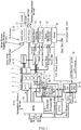
- FIG. 1 is a schematic view of a system for an engine having an idling stop function, to which the present invention is applied.
- an engine 1 includes a power generator 2 and an air conditioner compressor 4, the power generator 2 and the air conditioner compressor 4 being provided respectively on one side face and another side face of the engine 1 via brackets or the like, not shown in the figure.
- a belt 8 is wound around a crank pulley 5 mounted on a tip end of a crankshaft of the engine 1, a power generator pulley 6 mounted on a tip end of a rotary shaft of the power generator 2, and a compressor pulley 7 mounted on a tip end of a rotary shaft of the air conditioner compressor 4, whereby the respectively pulleys 5, 6, 7 are mechanically coupled to each other.
- crank pulley 5 the power generator pulley 6, and the compressor pulley 7 are mechanically coupled to each other by the single belt 8, but instead, the power generator pulley 6 and the compressor pulley 7 may be coupled respectively to the crank pulley 5 by different belts 8. Moreover, chains may be used instead of belts.
- the engine 1 includes a starter 9 provided in the vicinity of a coupling portion coupled to an automatic transmission 11.
- the starter 9 includes a pinion gear that advances and retreats in a similar manner to a typical starting starter.
- the starter 9 When the starter 9 is activated, the pinion gear engages with a gear provided on an outer periphery of a drive plate that is mounted on a base end portion of the crankshaft, and as a result, cranking is performed. Power supply to the starter 9 will be described below.
- the automatic transmission 11 includes an electric oil pump 10 for securing control oil pressure during an idling stop.
- the electric oil pump 10 is activated in response to a command from an automatic transmission controller 20 in order to improve responsiveness during vehicle departure following an idling stop.
- the power generator 2 generates power when driven by driving force from the engine 1, and during power generation, a generated voltage can be controlled variably by LIN (Local Interconnect Network) communication or hard-wire.
- the power generator 2 is also capable of regenerating kinetic energy produced by the vehicle as electric power when the vehicle decelerates. Power generation and regeneration are controlled by an engine control module (referred to hereafter as an ECM) 19.
- ECM engine control module
- the ECM 19 reads detection signals from various sensors, such as a crank angle sensor 12, a battery sensor, and an atmospheric pressure sensor, and signals from various switches, such as a brake switch, and controls a fuel injection amount, an ignition timing, and so on, as well as executing idling stop control. Further, the ECM 19 implements intercommunication between an ABS/VDC unit 21, an air conditioner amplifier 22, an electric power steering unit 25, a vehicle control controller 26, a power supply distribution controller 23, a meter unit 24, and a driver assistance system (ADAS) unit 27 via a CAN (Controller Area Network) in order to implement optimum control on the vehicle.
- sensors such as a crank angle sensor 12, a battery sensor, and an atmospheric pressure sensor
- switches such as a brake switch
- the ECM 19 is constituted by a microcomputer having a central processing unit (CPU), a read-only memory (ROM), a random access memory (RAM), and an input/output interface (I/O interface).
- the ECM 19 may also be constituted by a plurality of microcomputers.
- the system shown in FIG. 1 includes two secondary batteries, namely a lead storage battery serving as a first storage unit and a non-aqueous electrolyte secondary battery serving as a second storage unit.
- the lead storage battery is a lead acid battery 15
- the non-aqueous electrolyte secondary battery is a lithium ion secondary battery 16.
- an open-circuit voltage of the lead acid battery 15 in a fully charged state is 12.7 V
- an open-circuit voltage of the lithium ion secondary battery 16 in a fully charged state is 13.1 V.
- the lead acid battery 15 and the lithium ion secondary battery 16 are connected to each other in parallel via two paths C1, C2, while a MOSFET 50 and a lead acid battery path relay 51 that together function as switching unit are each connected to one of the two paths.
- the lead acid battery 15 supplies power to an overall electrical load 30.
- the lead acid battery path relay 51 is switched OFF (to a non-conductive condition) at a starting stage of an automatic engine restart following an idling stop to prevent a momentary voltage decrease (also referred to hereafter as a voltage drop), which occurs when the starter 9 is driven, from having an effect.
- a momentary voltage decrease also referred to hereafter as a voltage drop
- Power generated by the power generator 2 (including power generated by regeneration; likewise hereafter) is charged to both the lead acid battery 15 and the lithium ion secondary battery 16.
- typical idling stop control is executed. More specifically, when various conditions are satisfied, for example when an accelerator pedal is fully closed, a brake pedal is depressed, a vehicle speed is no higher than a predetermined vehicle speed, and so on, the engine 1 is automatically stopped, and when a depression amount of the brake pedal falls to or below a predetermined amount, the engine 1 is automatically restarted.
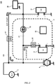
- FIG. 2 is a view illustrating a first configuration (also referred to hereafter as a type 1 power supply system) of a power supply system for supplying power to the starter 9 and the electrical load 30.
- a first configuration also referred to hereafter as a type 1 power supply system
- the lead acid battery 15 and the lithium ion secondary battery 16 are connected to each other in parallel by the two paths C1 and C2.
- the lead acid battery path relay 51 is connected to one of the paths, namely the path C2, as a first switch for switching the path C2 between a conductive condition and a non-conductive condition.
- the MOSFET 50 is connected to the other path, namely the path C1, as a second switch for switching the path C1 between a conductive condition and a non-conductive condition.
- the lead acid battery path relay 51 and the MOSFET 50 together constitute switching unit.
- the lead acid battery path relay 51 is disposed on the path C2 that extends from the lithium ion secondary battery 16 to the lead acid battery 15, while the MOSFET 50 is disposed on the path C1 that extends from the lithium ion secondary battery 16 to the lead acid battery 15.
- the MOSFET 50 is connected such that a forward direction of a parasitic diode thereof matches a direction heading from the lithium ion secondary battery 16 side toward the lead acid battery 15 side. As a result, electrical conduction from the lead acid battery 15 to the lithium ion secondary battery 16 on the path C1 is prevented regardless of the ON/OFF condition of the MOSFET 50. Further, a so-called normally closed type relay, which remains in an ON condition (a conductive condition) when a coil thereof is not energized, is used as the lead acid battery path relay 51. It should be noted that a momentary maximum current capacity of the MOSFET 50 is 180 A, for example, and a momentary maximum current capacity of the lead acid battery path relay 51 is 1200 A, for example.
- a lithium ion secondary battery-attached relay 52 is connected in series to the lithium ion secondary battery 16.
- the lithium ion secondary battery-attached relay 52 is constituted by a so-called normally open type relay, which remains in an OFF condition (a non-conductive condition) when a coil thereof is not energized.
- the momentary maximum current capacity of the lithium ion secondary battery-attached relay 52 is 800 A, for example.
- the lithium ion secondary battery 16, the lithium ion secondary battery-attached relay 52, the MOSFET 50, and a batter controller 60 are packaged together to form a lithium battery pack P.
- the battery controller 60 receives a signal relating to a discharge command or a charge command applied to the starter 9 or the overall electrical load 30 in accordance with operating conditions of the engine 1 from the ECM 19, and executes ON/OFF control on the lithium ion secondary battery-attached relay 52 and the MOSFET 50 on the basis of this signal.
- the overall electrical load 30 is connected to the lead acid battery 15 side of the lead acid battery path relay 51.
- the starter 9 and the power generator 2 are connected to the lithium ion secondary battery 16 side of the lead acid battery path relay 51.
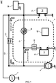
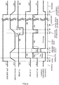
- FIG. 3 is a view illustrating a second configuration (also referred to hereafter as a type 2 power supply system) of a power supply system for supplying power to the starter 9 and the electrical load 30. It should be noted that identical reference symbols have been allocated to elements that are identical to the respective elements shown in FIG. 2 .
- a type 2 power supply system 100' differs from the type 1 power supply system 100 shown in FIG. 2 in that a motor 70 is used instead of the power generator 2, and the starter 9 is connected to the lead acid battery 15 side of the lead acid battery path relay 51.
- the motor 70 includes a pulley that corresponds to the power generator pulley 6, and the pulley is mechanically coupled to the crank pulley 5 by a belt or the like.
- the motor 70 includes an inverter, and functions as a motor when driven by power supplied from the lithium ion secondary battery 16, and as a power generator that generates power when driven by driving force from the engine 1. Further, when the power generation function of the motor 70 is used, a generated voltage can be controlled variably.
- the ECM 19 switches between the motor function and the power generation function.
- the motor function is used mainly at the starting stage of an automatic engine restart following an idling stop.
- the motor 70 serves as engine restarting unit.
- the starter 9 is used only during an initial start (a start other than an automatic restart).
- a starter having identical specifications to a starter of a vehicle not having an idling stop function may be used as the starter 9.
- the lead acid battery 15 and the starter 9 are provided on the same side of the lead acid battery path relay 51, and therefore a current does not flow through the lead acid battery path relay 51 when power is supplied to the starter 9 from the lead acid battery 15 during an initial start of the engine 1.
- the current capacity of the lead acid battery path relay 51 can be reduced in comparison with that of the lead acid battery path relay 51 used in the type 1 power supply system 100, enabling a reduction in the construction cost of the lead acid battery path relay 51.
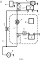
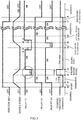
- FIG. 4 is a view illustrating a third configuration (also referred to hereafter as a type 3 power supply system) of a power supply system for supplying power to the starter 9 and the electrical load 30.
- a type 3 power supply system 100" differs from the type 1 power supply system 100 shown in FIG. 2 in that the power generator 2 is connected to the lead acid battery 15 side of the lead acid battery path relay 51.
- FIG. 8 is a time chart illustrating ON/OFF control implemented on the lead acid battery path relay 51, the lithium ion secondary battery-attached relay 52, and the MOSFET 50 according to a reference example. This figure shows respective ON/OFF conditions of the lead acid battery path relay 51, the lithium ion secondary battery-attached relay 52, and the MOSFET 50 over time in accordance with the ON/OFF condition of an ignition key (not shown) and the magnitude of the engine speed.
- the lead acid battery path relay 51, the lithium ion secondary battery-attached relay 52, and the MOSFET 50 when the lead acid battery path relay 51, the lithium ion secondary battery-attached relay 52, and the MOSFET 50 are ON, this means that the respective components are conductive, and when the lead acid battery path relay 51, the lithium ion secondary battery-attached relay 52, and the MOSFET 50 are OFF, this means that the respective components are non-conductive.
- the time chart shown in FIG. 8 is applied to the configuration of the power supply system 100 shown in FIG. 2 , but the time chart shown in FIG. 8 may be applied similarly to the respective configurations of the power supply system 100' shown in FIG. 3 and the power supply system 100" shown in FIG. 4 .
- the normally closed type lead acid battery path relay 51 is ON, the MOSFET 50 is OFF, and the normally open type lithium ion secondary battery-attached relay 52 is OFF.
- the battery controller 60 may switch the lithium ion secondary battery-attached relay 52 ON so that power is supplied to the starter 9 from the two batteries, i.e. the lead acid battery 15 and the lithium ion secondary battery 16.
- the battery controller 60 switches the lithium ion secondary battery-attached relay 52 ON.
- the power generated by the power generator 2 can be charged to the lithium ion secondary battery 16 along the path C2, as well as to the lead acid battery 15.
- the power generated by the power generator 2 is charged mainly to the lithium ion secondary battery 16.
- the battery controller 60 switches the MOSFET 50 ON. Then, following the elapse of a predetermined time ⁇ t after the time t2, the ECM 19 switches the lead acid battery path relay 51 OFF.
- the lead acid battery path relay 51 By switching the lead acid battery path relay 51 OFF following the elapse of a predetermined time after the MOSFET 50 is switched ON in this manner, the lead acid battery path relay 51 can be switched OFF in a condition where a potential difference between respective ends thereof has decreased, and as a result, an arc can be prevented from occurring when the current is cut off.
- the predetermined time ⁇ t may be set appropriately at a sufficient time for eliminating, to a certain extent, the potential difference between the respective ends of the lead acid battery path relay 51.
- the lead acid battery path relay 51 is maintained in the OFF condition, and the battery controller 60 maintains the MOSFET 50 and the lithium ion secondary battery-attached relay 52 in the ON condition.
- the battery controller 60 preferably switches the lithium ion secondary battery-attached relay 52 OFF. In so doing, a situation in which an overvoltage is applied to the lithium ion secondary battery 16 is prevented from occurring.
- the lithium ion secondary battery 16 due to characteristics of the lithium ion secondary battery 16 and the lead acid battery 15, power is supplied to the overall electrical load 30 mainly from the lithium ion secondary battery 16. Furthermore, as noted above, it is easier to charge the generated power to the lithium ion secondary battery 16, and therefore the voltage of the lithium ion secondary battery 16 is maintained at or above the voltage of the lead acid battery 15 except during the starting stage of an automatic restart, in which the starter 9 is driven by the power of the lithium ion secondary battery 16, as will be described below.
- the lithium ion secondary battery 16 has a higher energy density and a higher charging/ discharging energy efficiency than the lead acid battery 15. Moreover, dissolution/precipitation reactions do not occur in electrode material of the lithium ion secondary battery 16 during charging and discharging, meaning that the lithium ion secondary battery 16 has a longer expected lifespan.
- the battery controller 60 switches the MOSFET 50 OFF.
- the lead acid battery path relay 51 and the MOSFET 50 are both OFF, and therefore electrical conduction between the starter 9 side (the lithium ion secondary battery 16) and the overall electrical load 30 side (the lead acid battery 15) is completely cut off.
- the lithium ion secondary battery-attached relay 52 is maintained in the ON condition, and therefore electrical conduction between the lithium ion secondary battery 16 and the starter 9 is secured so that the starter 9 can be started by discharging the lithium ion secondary battery 16.
- a predetermined resistor and a bypass relay connected in parallel thereto may be interposed between the lithium ion secondary battery 16 and the starter 9.
- the bypass relay by switching the bypass relay from a non-conductive condition to a conductive condition approximately 100 to 150 ms after the starter 9 is driven by power supplied from the lithium ion secondary battery 16, a spike current generated when the starter 9 is started can be greatly reduced so that a favourable starting performance is secured.
- control for returning to a normal traveling condition is implemented a predetermined time after the completion of an engine starting operation.
- a restart initial stage (the time t5 to a time t6) begins.
- the battery controller 60 switches the MOSFET 50 ON.
- the ECM 19 switches the lead acid battery path relay 51 ON a predetermined time ( ⁇ t' in the figure) after the MOSFET 50 is switched ON.
- the MOSFET 50 is switched ON first, whereupon the lead acid battery path relay 51 is switched ON following the elapse of the predetermined time (a delay) ⁇ t. Therefore, at the beginning of the restart initial stage (the time t5), the path C1 can be made electrically conductive without delay by the MOSFET 50, which has a higher response speed than the lead acid battery path relay 51, such that power can be discharged to the overall electrical load 30 from both the lead acid battery 15 and the lithium ion secondary battery 16. Furthermore, by switching the MOSFET 50 ON, the potential difference between the respective ends of the lead acid battery path relay 51 is reduced. Therefore, by switching the lead acid battery path relay 51 ON in this condition, an inrush current is prevented from occurring.
- the battery controller 60 switches the MOSFET 50 OFF.
- an engine stop stage in which the ignition key is switched OFF, begins.
- a period from the time t7 to a time t8 corresponds to a stoppage starting stage, which lasts until the engine is stopped.
- the normally open type lithium ion secondary battery-attached relay 52 is switched OFF at the time t8, at which an engine revolution speed reaches zero.
- the normally closed type lead acid battery path relay 51 meanwhile, is kept ON.
- the lead acid battery path relay 51 and the MOSFET 50 are switched OFF at the starting stage of an automatic restart of the engine 1 such that a power supply path from the lead acid battery 15 to the starter 9 is cut off. Accordingly, only the power of the lithium ion secondary battery 16 is used during the automatic restart, and therefore the replacement cycle of the lead acid battery 15 can be lengthened.
- electrical conduction between the lead acid battery 15 and the starter 9 is switched ON and OFF using both the MOSFET 50 and the lead acid battery path relay 51.
- electrical conduction may be switched ON and OFF using either one of the MOSFET 50 and the lead acid battery path relay 51 alone, or using another switch.
- the lead acid battery path relay 51 is switched to the OFF condition during the idling stop, since the MOSFET 50 is also switched OFF, power can no longer be supplied from the lithium ion secondary battery 16 during the idling stop.
- the lead acid battery path relay 51 and the MOSFET 50 are switched OFF and ON, respectively, during the idling stop (the time t3 to the time t4), and at the start of the automatic restart (the time t4), the highly responsive MOSFET 50 is switched from the ON condition to the OFF condition.
- the power supply path from the lead acid battery 15 to the starter 9 can be cut off reliably, and as a result, the automatic restart can be executed quickly without causing a voltage drop to occur in the overall electrical load 30.
- the voltage of the lithium ion secondary battery 16 takes a value that equals or exceeds the voltage of the lead acid battery 15 at all times except for the restart starting stage (the time t4 to the time t5).
- the voltage of the lead acid battery 15 exceeds the voltage of the lithium ion secondary battery 16, such that a current can flow from the lead acid battery 15 side to the lithium ion secondary battery 16 side, only during the restart starting stage (the time t4 to the time t5). Therefore, by switching the lead acid battery path relay 51 and the MOSFET 50 OFF during the restart starting stage (the time t4 to the time t5), a current can be prevented from flowing from the lead acid battery 15 side to the lithium ion secondary battery 16 side.
- a current can be prevented from flowing from the lead acid battery 15 side to the lithium ion secondary battery 16 side without disposing a MOSFET having a parasitic diode with a forward direction that is oriented in an opposite direction to the forward direction of a parasitic diode of the MOSFET 50.
- the number of used MOSFETs can be reduced, enabling a reduction in cost.
- the power supply system 100 As regards a part connecting the lead acid battery 15 to the overall electrical load 30, the power supply system 100 according to this reference example is configured similarly to an electrical circuit of a typical vehicle including only one battery.
- the lead acid battery 15 can be formed to identical specifications to a lead acid battery provided in a vehicle not having an idling stop function. As a result, the cost of installing an idling stop system in the vehicle can be reduced.
- the lithium ion secondary battery pack P includes the lithium ion secondary battery 16, the MOSFET 50, the lithium ion secondary battery-attached relay 52, and the battery controller 60, whereas the lead acid battery path relay 51 is disposed outside the lithium ion secondary battery pack P.
- the lead acid battery path relay 51 may be disposed in the lithium battery pack P while remaining parallel to the MOSFET 50.
- the battery controller 60 may be provided outside the lithium ion secondary battery pack P.
- FIG. 5 is a time chart illustrating switching control implemented on the lead acid battery path relay 51, the lithium ion secondary battery-attached relay 52, and the MOSFET 50 according to this embodiment.
- the ON/OFF control chart of the reference example shown in FIG. 8 is shown by dotted lines in the figure in relation to the lead acid battery path relay 51 and the MOSFET 50.
- the figure also shows a charge/discharge command chart.
- the charge/discharge command chart shows a positive value only during deceleration regeneration, i.e. from the time t2 to the time t3. Accordingly, from the time t2 to the time t3, a charge command is issued to charge the lead acid battery 15 and the lithium ion secondary battery 16.
- a discharge command is issued to discharge the lead acid battery 15 and the lithium ion secondary battery 16.
- a discharge amount ratio of the lead acid battery 15 and the lithium ion secondary battery 16 can be adjusted favorably while the discharge command is issued.
- the battery controller 60 switches the MOSFET 50 from the OFF condition to the ON condition.
- the lead acid battery path relay 51 is maintained in the ON condition up to a predetermined time ⁇ t4 prior to the time t4 at which the idling stop is terminated.
- the ECM 19 switches the lead acid battery path relay 51 to the OFF condition.
- the restart starting stage is then terminated and the restart initial stage begins (the time t5).
- the ECM 19 switches the lead acid battery path relay 51 back ON.
- the lead acid battery path relay 51 and the MOSFET 50 are maintained in the ON condition at all times except during the restart starting stage (the time t4 to the time t5) and for a predetermined time before and after the restart starting stage.
- discharge is performed from the lithium ion secondary battery 16 to the overall electrical load 30 on the lead acid battery 15 side along both the path C1 and the path C2 over the entire period in which the discharge command is issued, except for the restart starting stage (the time t4 to the time t5) and a predetermined time before and after the restart starting stage.
- harness resistance can be reduced, enabling an increase in the discharge amount from the lithium ion secondary battery 16 to the overall electrical load 30, and as a result, the discharge amount from the lead acid battery 15 to the overall electrical load 30 can be suppressed.
- the power supply system 100 employing the control according to this embodiment is applied to a vehicle having an idling stop function for executing an automatic stop and an automatic restart on an engine.
- the power supply system 100 includes the power generator 2, the lead acid battery 15 that can be charged with and can discharge the power generated by the power generator 2, the lithium ion secondary battery 16 that can be charged with and can discharge the generated power, the two paths C1, C2 connecting the lead acid battery 15 and the lithium ion secondary battery 16, the engine restarting unit 9 connected to either the lead acid battery 15 or the lithium ion secondary battery 16 in order to start the engine 1 at the start of an automatic restart, the electrical load 30 of the vehicle, which is connected to the lead acid battery 15, the lead acid battery path relay 51 for switching the path C2 between the conductive condition and the non-conductive condition, the MOSFET 50 for switching the other path C1 between the conductive condition and the non-conductive condition, and the ECM 19 and the battery controller 60 for implementing ON/OFF control on the lead acid battery path relay 51 and the MOSFET 50.
- the control unit 19, 60 switches both the lead acid battery path relay 51 and the MOSFET 50 to the conductive condition while the engine 1 is operative, except during the starting stage of the automatic restart following an idling stop, and during an idling stop.
- the starting stage of the automatic restart is assumed to include the time zone extending from the predetermined time ⁇ t4 before the time t4 to the predetermined time ⁇ t5 after the time t5, in addition to the period extending from the time t4 to the time t5, which serves as the restart starting stage shown in FIG. 5 and described above.
- the starting stage of the automatic restart refers to a time zone extending from a time t4 - ⁇ t4 to a time t5 + ⁇ t5 in FIG. 5 .
- the MOSFET 50 and the lead acid battery path relay 51 are maintained in the conductive condition at all times except for the starting stage of the automatic restart (the time t4 - ⁇ t4 to the time t5 + ⁇ t5). Accordingly, the two paths C1, C2 extending from the lithium ion secondary battery 16 serving as the second storage unit to the lead acid battery 15 serving as the first storage unit are both conductive.
- control according to this embodiment is not limited to the type 1 power supply system 100 shown in FIG. 2 , and may also be applied to the type 2 power supply system 100' shown in FIG. 3 or the type 3 power supply system 100" shown in FIG. 4 .
- FIG. 6 is a time chart illustrating switching control implemented on the lead acid battery path relay 51, the lithium ion secondary battery-attached relay 52, and the MOSFET 50 according to this embodiment.
- This embodiment differs from the control according to the first embodiment, shown in FIG. 5 , in that during the deceleration regeneration stage (the time t2 to the time t3), in which the charge command is issued, the battery controller 60 switches the MOSFET 50 OFF (see the encircled part of the figure).
- the battery controller 60 switches the MOSFET 50, which serves as a second switch, to the non-conductive condition when deceleration regeneration is underway in the automobile.
- the path C1 is non-conductive, and therefore only the path C2 extends from the power generator 2 to the lithium ion secondary battery 16.
- harness resistance from the power generator 2 to the lithium ion secondary battery 16 increases in comparison with a case where the path C1 and the path C2 can both be used, and therefore a charging amount charged to the lithium ion secondary battery 16 is suppressed, leading to an inevitable increase in the charging amount charged to the lead acid battery 15.
- a charging share ratio of the lead acid battery 15 can be increased during charging, and as a result, a state of charge (SOC) of the lead acid battery 15 can be increased.
- control according to this embodiment is not limited to the type 3 power supply system 100" shown in FIG. 4 , and may also be applied to the type 1 power supply system 100 shown in FIG. 2 or the type 2 power supply system 100' shown in FIG. 3 .
- a third embodiment will now be described. Identical reference numerals have been allocated to identical elements to those of the first embodiment, and description thereof has been omitted. It is assumed that the power supply system 100' having the configuration shown in FIG. 3 is used in the control according to this embodiment. A particularly important part of this embodiment is that the motor 70 functioning as a power generator is disposed on the side of the lithium ion secondary battery 16 serving as the second storage unit.
- FIG. 7 is a time chart illustrating switching control implemented on the lead acid battery path relay 51, the lithium ion secondary battery-attached relay 52, and the MOSFET 50 according to this embodiment.
- This embodiment differs from the first embodiment shown in FIG. 5 in that during the deceleration regeneration stage (the time t2 to the time t3), when the charge command is issued, the lead acid battery path relay 51 is switched OFF (see the encircled part of the figure).
- the motor 70 serving as a power generator is disposed on the lithium ion secondary battery 16 side.
- the battery controller 60 switches the lead acid battery path relay 51 to the non-conductive condition when deceleration regeneration is underway in the automobile.
- the path C2 is non-conductive, and therefore the path C1 must be used to connect the motor 70 to the lead acid battery 15 serving as the first storage unit.
- the generated power passes through the lithium ion secondary battery 16 serving as the second storage unit when traveling from the motor 70 to the lead acid battery 15, whereby the power of the motor 70 is charged preferentially to the lithium ion secondary battery 16.
- the charging share ratio of the lithium ion secondary battery 16 can be increased, and as a result, the state of charge (SOC) of the lithium ion secondary battery 16 can be increased.
- the generated power is charged preferentially to the lithium ion secondary battery 16 while traveling from the motor 70 to the lead acid battery 15, and therefore the voltage actually supplied to the lead acid battery 15 drops, thereby preventing the voltage charged to the lead acid battery 15 from becoming excessive.
- the power supplied to the overall electrical load 30, which is disposed on the lead acid battery 15 side can also be suppressed, and therefore a situation in which an overvoltage is applied to the overall electrical equipment load 30 can be reliably prevented from occurring.
- control according to this embodiment is not limited to the type 2 power supply system 100' shown in FIG. 3 , and may also be applied to the type 2 power supply system 100 shown in FIG. 2 .
- the first storage unit is not limited to the lead acid battery 15, and a lead-free secondary battery such as a nickel hydrogen battery, for example, may be used instead.
- switching elements employing semiconductors may be used instead of the mechanical relays used in the embodiments.
Landscapes
- Engineering & Computer Science (AREA)
- Mechanical Engineering (AREA)
- Power Engineering (AREA)
- Transportation (AREA)
- Sustainable Energy (AREA)
- Life Sciences & Earth Sciences (AREA)
- Sustainable Development (AREA)
- Combustion & Propulsion (AREA)
- General Engineering & Computer Science (AREA)
- Chemical & Material Sciences (AREA)
- Charge And Discharge Circuits For Batteries Or The Like (AREA)
- Control Of Charge By Means Of Generators (AREA)
- Stand-By Power Supply Arrangements (AREA)
- Secondary Cells (AREA)
- Control Of Vehicle Engines Or Engines For Specific Uses (AREA)
Applications Claiming Priority (1)
| Application Number | Priority Date | Filing Date | Title |
|---|---|---|---|
| PCT/JP2015/063623 WO2016181495A1 (ja) | 2015-05-12 | 2015-05-12 | 電源システム |
Publications (3)
| Publication Number | Publication Date |
|---|---|
| EP3296159A1 EP3296159A1 (en) | 2018-03-21 |
| EP3296159A4 EP3296159A4 (en) | 2018-03-21 |
| EP3296159B1 true EP3296159B1 (en) | 2019-10-09 |
Family
ID=57248958
Family Applications (1)
| Application Number | Title | Priority Date | Filing Date |
|---|---|---|---|
| EP15891820.1A Active EP3296159B1 (en) | 2015-05-12 | 2015-05-12 | Power supply system |
Country Status (10)
| Country | Link |
|---|---|
| US (1) | US10119513B2 (ja) |
| EP (1) | EP3296159B1 (ja) |
| JP (1) | JP6384601B2 (ja) |
| KR (1) | KR101833190B1 (ja) |
| CN (1) | CN107531201B (ja) |
| BR (1) | BR112017024103B1 (ja) |
| CA (1) | CA2985749C (ja) |
| MX (1) | MX369581B (ja) |
| RU (1) | RU2668491C1 (ja) |
| WO (1) | WO2016181495A1 (ja) |
Families Citing this family (7)
| Publication number | Priority date | Publication date | Assignee | Title |
|---|---|---|---|---|
| JP6620674B2 (ja) * | 2016-05-26 | 2019-12-18 | 株式会社オートネットワーク技術研究所 | 給電制御装置、給電制御方法及びコンピュータプログラム |
| US10697417B2 (en) * | 2017-10-06 | 2020-06-30 | Briggs & Stratton Corporation | Battery connections for battery start of internal combustion engines |
| CN109572600A (zh) * | 2018-11-20 | 2019-04-05 | 福建工程学院 | 可侦测车辆运转状态的开关装置及控制方法 |
| US10804732B2 (en) * | 2019-01-16 | 2020-10-13 | Black Energy Co., Ltd | Power supply device using electromagnetic power generation |
| KR102613199B1 (ko) * | 2019-04-29 | 2023-12-14 | 현대자동차주식회사 | 차량 및 그의 제어 방법 |
| CN112744101B (zh) * | 2020-12-25 | 2023-02-17 | 中国第一汽车股份有限公司 | 充放电控制系统、方法及交通工具 |
| WO2023095342A1 (ja) * | 2021-11-29 | 2023-06-01 | 日産自動車株式会社 | 電源システム及び電源システムの制御方法 |
Citations (2)
| Publication number | Priority date | Publication date | Assignee | Title |
|---|---|---|---|---|
| EP1137150A2 (de) * | 2000-03-22 | 2001-09-26 | Volkswagen Aktiengesellschaft | Zwei-Batteriensystem |
| US20140285003A1 (en) * | 2013-03-20 | 2014-09-25 | Robert Bosch Gmbh | Vehicle electrical network having at least two energy storage devices, method for operating a vehicle electrical network, and means for the implementation thereof |
Family Cites Families (14)
| Publication number | Priority date | Publication date | Assignee | Title |
|---|---|---|---|---|
| JP2004222473A (ja) * | 2003-01-17 | 2004-08-05 | Toyota Motor Corp | 車両用電源システム及び充電方法 |
| EP2154028B8 (en) * | 2003-02-17 | 2015-12-09 | Denso Corporation | Vehicle power supply system |
| JP3972906B2 (ja) | 2003-04-09 | 2007-09-05 | 株式会社デンソー | 車両用電源システム |
| JP4842885B2 (ja) * | 2007-05-23 | 2011-12-21 | トヨタ自動車株式会社 | 車載機器制御システムおよび車両 |
| JP4853456B2 (ja) | 2007-10-29 | 2012-01-11 | マツダ株式会社 | エンジンの自動停止装置 |
| EP2272722B1 (en) | 2009-07-01 | 2015-04-08 | Denso Corporation | Power source apparatus for vehicle |
| JP5234052B2 (ja) | 2010-04-27 | 2013-07-10 | 株式会社デンソー | 電源装置 |
| JP5488529B2 (ja) * | 2011-05-17 | 2014-05-14 | マツダ株式会社 | 車両の電源制御装置 |
| JP5834860B2 (ja) | 2011-12-08 | 2015-12-24 | マツダ株式会社 | 車両の電源制御装置 |
| JP5811055B2 (ja) * | 2012-07-11 | 2015-11-11 | 株式会社デンソー | バッテリシステム制御装置 |
| JP5930041B2 (ja) * | 2012-07-27 | 2016-06-08 | 日産自動車株式会社 | 車両の制御装置および車両の制御方法 |
| DE102012017674A1 (de) * | 2012-09-07 | 2014-03-13 | Audi Ag | Kraftfahrzeug mit einem Mehrspannungs-Bordnetz und zugehöriges Verfahren |
| JP2015009791A (ja) * | 2013-07-02 | 2015-01-19 | 本田技研工業株式会社 | 車両用電源装置 |
| JP6380171B2 (ja) * | 2015-03-06 | 2018-08-29 | 株式会社デンソー | 電源システム |
-
2015
- 2015-05-12 BR BR112017024103-0A patent/BR112017024103B1/pt active IP Right Grant
- 2015-05-12 RU RU2017142982A patent/RU2668491C1/ru active
- 2015-05-12 JP JP2017517517A patent/JP6384601B2/ja not_active Expired - Fee Related
- 2015-05-12 WO PCT/JP2015/063623 patent/WO2016181495A1/ja active Application Filing
- 2015-05-12 CA CA2985749A patent/CA2985749C/en active Active
- 2015-05-12 CN CN201580079747.3A patent/CN107531201B/zh active Active
- 2015-05-12 KR KR1020177032883A patent/KR101833190B1/ko active IP Right Grant
- 2015-05-12 MX MX2017014027A patent/MX369581B/es active IP Right Grant
- 2015-05-12 EP EP15891820.1A patent/EP3296159B1/en active Active
- 2015-05-12 US US15/573,728 patent/US10119513B2/en active Active
Patent Citations (2)
| Publication number | Priority date | Publication date | Assignee | Title |
|---|---|---|---|---|
| EP1137150A2 (de) * | 2000-03-22 | 2001-09-26 | Volkswagen Aktiengesellschaft | Zwei-Batteriensystem |
| US20140285003A1 (en) * | 2013-03-20 | 2014-09-25 | Robert Bosch Gmbh | Vehicle electrical network having at least two energy storage devices, method for operating a vehicle electrical network, and means for the implementation thereof |
Also Published As
| Publication number | Publication date |
|---|---|
| BR112017024103A2 (ja) | 2018-07-24 |
| CN107531201B (zh) | 2019-03-15 |
| US20180126856A1 (en) | 2018-05-10 |
| US10119513B2 (en) | 2018-11-06 |
| EP3296159A1 (en) | 2018-03-21 |
| CN107531201A (zh) | 2018-01-02 |
| MX369581B (es) | 2019-11-13 |
| WO2016181495A1 (ja) | 2016-11-17 |
| CA2985749A1 (en) | 2016-11-17 |
| JPWO2016181495A1 (ja) | 2018-03-01 |
| MX2017014027A (es) | 2018-03-08 |
| RU2668491C1 (ru) | 2018-10-01 |
| KR20170130611A (ko) | 2017-11-28 |
| CA2985749C (en) | 2019-02-26 |
| JP6384601B2 (ja) | 2018-09-05 |
| EP3296159A4 (en) | 2018-03-21 |
| KR101833190B1 (ko) | 2018-02-27 |
| BR112017024103B1 (pt) | 2022-07-05 |
Similar Documents
| Publication | Publication Date | Title |
|---|---|---|
| EP3075989B1 (en) | Electric circuit | |
| EP3296159B1 (en) | Power supply system | |
| CN108656968B (zh) | 车辆用电源装置 | |
| US9273603B2 (en) | Vehicle-mounted power supply system | |
| JP6371791B2 (ja) | 車両用電源装置 | |
| CN103545903A (zh) | 电池系统控制器 | |
| JP6691502B2 (ja) | 車両用電源装置 | |
| CN109952236B (zh) | 车辆用电源系统的控制方法和车辆用电源系统 | |
| JP2020096402A (ja) | 車両用電源装置 | |
| EP3299223B1 (en) | Power supply system control device and power supply system control method | |
| JP2018198519A (ja) | 車両用電源装置 | |
| WO2015189902A1 (ja) | 車両用電気回路 | |
| JP2016220427A (ja) | 電源装置 | |
| JP6572621B2 (ja) | 電気回路 | |
| JP2016220443A (ja) | 電源システム |
Legal Events
| Date | Code | Title | Description |
|---|---|---|---|
| STAA | Information on the status of an ep patent application or granted ep patent |
Free format text: STATUS: THE INTERNATIONAL PUBLICATION HAS BEEN MADE |
|
| PUAI | Public reference made under article 153(3) epc to a published international application that has entered the european phase |
Free format text: ORIGINAL CODE: 0009012 |
|
| STAA | Information on the status of an ep patent application or granted ep patent |
Free format text: STATUS: REQUEST FOR EXAMINATION WAS MADE |
|
| 17P | Request for examination filed |
Effective date: 20171124 |
|
| A4 | Supplementary search report drawn up and despatched |
Effective date: 20180126 |
|
| AK | Designated contracting states |
Kind code of ref document: A1 Designated state(s): AL AT BE BG CH CY CZ DE DK EE ES FI FR GB GR HR HU IE IS IT LI LT LU LV MC MK MT NL NO PL PT RO RS SE SI SK SM TR |
|
| AX | Request for extension of the european patent |
Extension state: BA ME |
|
| STAA | Information on the status of an ep patent application or granted ep patent |
Free format text: STATUS: EXAMINATION IS IN PROGRESS |
|
| DAV | Request for validation of the european patent (deleted) | ||
| DAX | Request for extension of the european patent (deleted) | ||
| 17Q | First examination report despatched |
Effective date: 20180801 |
|
| RIC1 | Information provided on ipc code assigned before grant |
Ipc: B60L 50/50 20190101ALI20190401BHEP Ipc: B60L 7/10 20060101ALI20190401BHEP Ipc: B60L 50/16 20190101ALI20190401BHEP Ipc: B60R 16/023 20060101ALI20190401BHEP Ipc: B60R 16/033 20060101AFI20190401BHEP Ipc: F02N 11/08 20060101ALI20190401BHEP Ipc: H02J 7/14 20060101ALI20190401BHEP Ipc: B60R 16/03 20060101ALI20190401BHEP |
|
| GRAP | Despatch of communication of intention to grant a patent |
Free format text: ORIGINAL CODE: EPIDOSNIGR1 |
|
| STAA | Information on the status of an ep patent application or granted ep patent |
Free format text: STATUS: GRANT OF PATENT IS INTENDED |
|
| INTG | Intention to grant announced |
Effective date: 20190722 |
|
| GRAS | Grant fee paid |
Free format text: ORIGINAL CODE: EPIDOSNIGR3 |
|
| GRAA | (expected) grant |
Free format text: ORIGINAL CODE: 0009210 |
|
| STAA | Information on the status of an ep patent application or granted ep patent |
Free format text: STATUS: THE PATENT HAS BEEN GRANTED |
|
| RIN1 | Information on inventor provided before grant (corrected) |
Inventor name: KOISHI, AKIFUMI Inventor name: WATANABE, MUNEMITSU Inventor name: TSUCHIYA, TERUMASA Inventor name: TAHARA, MASAHIKO Inventor name: TEZUKA, ATSUSHI Inventor name: KOIKE, TOMOYUKI |
|
| AK | Designated contracting states |
Kind code of ref document: B1 Designated state(s): AL AT BE BG CH CY CZ DE DK EE ES FI FR GB GR HR HU IE IS IT LI LT LU LV MC MK MT NL NO PL PT RO RS SE SI SK SM TR |
|
| REG | Reference to a national code |
Ref country code: GB Ref legal event code: FG4D |
|
| REG | Reference to a national code |
Ref country code: CH Ref legal event code: EP |
|
| REG | Reference to a national code |
Ref country code: DE Ref legal event code: R096 Ref document number: 602015039730 Country of ref document: DE |
|
| REG | Reference to a national code |
Ref country code: IE Ref legal event code: FG4D |
|
| REG | Reference to a national code |
Ref country code: AT Ref legal event code: REF Ref document number: 1188426 Country of ref document: AT Kind code of ref document: T Effective date: 20191115 |
|
| REG | Reference to a national code |
Ref country code: NL Ref legal event code: MP Effective date: 20191009 |
|
| REG | Reference to a national code |
Ref country code: LT Ref legal event code: MG4D |
|
| REG | Reference to a national code |
Ref country code: AT Ref legal event code: MK05 Ref document number: 1188426 Country of ref document: AT Kind code of ref document: T Effective date: 20191009 |
|
| PG25 | Lapsed in a contracting state [announced via postgrant information from national office to epo] |
Ref country code: GR Free format text: LAPSE BECAUSE OF FAILURE TO SUBMIT A TRANSLATION OF THE DESCRIPTION OR TO PAY THE FEE WITHIN THE PRESCRIBED TIME-LIMIT Effective date: 20200110 Ref country code: FI Free format text: LAPSE BECAUSE OF FAILURE TO SUBMIT A TRANSLATION OF THE DESCRIPTION OR TO PAY THE FEE WITHIN THE PRESCRIBED TIME-LIMIT Effective date: 20191009 Ref country code: BG Free format text: LAPSE BECAUSE OF FAILURE TO SUBMIT A TRANSLATION OF THE DESCRIPTION OR TO PAY THE FEE WITHIN THE PRESCRIBED TIME-LIMIT Effective date: 20200109 Ref country code: NO Free format text: LAPSE BECAUSE OF FAILURE TO SUBMIT A TRANSLATION OF THE DESCRIPTION OR TO PAY THE FEE WITHIN THE PRESCRIBED TIME-LIMIT Effective date: 20200109 Ref country code: PL Free format text: LAPSE BECAUSE OF FAILURE TO SUBMIT A TRANSLATION OF THE DESCRIPTION OR TO PAY THE FEE WITHIN THE PRESCRIBED TIME-LIMIT Effective date: 20191009 Ref country code: LV Free format text: LAPSE BECAUSE OF FAILURE TO SUBMIT A TRANSLATION OF THE DESCRIPTION OR TO PAY THE FEE WITHIN THE PRESCRIBED TIME-LIMIT Effective date: 20191009 Ref country code: AT Free format text: LAPSE BECAUSE OF FAILURE TO SUBMIT A TRANSLATION OF THE DESCRIPTION OR TO PAY THE FEE WITHIN THE PRESCRIBED TIME-LIMIT Effective date: 20191009 Ref country code: SE Free format text: LAPSE BECAUSE OF FAILURE TO SUBMIT A TRANSLATION OF THE DESCRIPTION OR TO PAY THE FEE WITHIN THE PRESCRIBED TIME-LIMIT Effective date: 20191009 Ref country code: NL Free format text: LAPSE BECAUSE OF FAILURE TO SUBMIT A TRANSLATION OF THE DESCRIPTION OR TO PAY THE FEE WITHIN THE PRESCRIBED TIME-LIMIT Effective date: 20191009 Ref country code: PT Free format text: LAPSE BECAUSE OF FAILURE TO SUBMIT A TRANSLATION OF THE DESCRIPTION OR TO PAY THE FEE WITHIN THE PRESCRIBED TIME-LIMIT Effective date: 20200210 Ref country code: ES Free format text: LAPSE BECAUSE OF FAILURE TO SUBMIT A TRANSLATION OF THE DESCRIPTION OR TO PAY THE FEE WITHIN THE PRESCRIBED TIME-LIMIT Effective date: 20191009 Ref country code: LT Free format text: LAPSE BECAUSE OF FAILURE TO SUBMIT A TRANSLATION OF THE DESCRIPTION OR TO PAY THE FEE WITHIN THE PRESCRIBED TIME-LIMIT Effective date: 20191009 |
|
| PG25 | Lapsed in a contracting state [announced via postgrant information from national office to epo] |
Ref country code: IS Free format text: LAPSE BECAUSE OF FAILURE TO SUBMIT A TRANSLATION OF THE DESCRIPTION OR TO PAY THE FEE WITHIN THE PRESCRIBED TIME-LIMIT Effective date: 20200224 Ref country code: RS Free format text: LAPSE BECAUSE OF FAILURE TO SUBMIT A TRANSLATION OF THE DESCRIPTION OR TO PAY THE FEE WITHIN THE PRESCRIBED TIME-LIMIT Effective date: 20191009 Ref country code: HR Free format text: LAPSE BECAUSE OF FAILURE TO SUBMIT A TRANSLATION OF THE DESCRIPTION OR TO PAY THE FEE WITHIN THE PRESCRIBED TIME-LIMIT Effective date: 20191009 |
|
| PG25 | Lapsed in a contracting state [announced via postgrant information from national office to epo] |
Ref country code: AL Free format text: LAPSE BECAUSE OF FAILURE TO SUBMIT A TRANSLATION OF THE DESCRIPTION OR TO PAY THE FEE WITHIN THE PRESCRIBED TIME-LIMIT Effective date: 20191009 |
|
| REG | Reference to a national code |
Ref country code: DE Ref legal event code: R097 Ref document number: 602015039730 Country of ref document: DE |
|
| PG2D | Information on lapse in contracting state deleted |
Ref country code: IS |
|
| PG25 | Lapsed in a contracting state [announced via postgrant information from national office to epo] |
Ref country code: DK Free format text: LAPSE BECAUSE OF FAILURE TO SUBMIT A TRANSLATION OF THE DESCRIPTION OR TO PAY THE FEE WITHIN THE PRESCRIBED TIME-LIMIT Effective date: 20191009 Ref country code: EE Free format text: LAPSE BECAUSE OF FAILURE TO SUBMIT A TRANSLATION OF THE DESCRIPTION OR TO PAY THE FEE WITHIN THE PRESCRIBED TIME-LIMIT Effective date: 20191009 Ref country code: CZ Free format text: LAPSE BECAUSE OF FAILURE TO SUBMIT A TRANSLATION OF THE DESCRIPTION OR TO PAY THE FEE WITHIN THE PRESCRIBED TIME-LIMIT Effective date: 20191009 Ref country code: RO Free format text: LAPSE BECAUSE OF FAILURE TO SUBMIT A TRANSLATION OF THE DESCRIPTION OR TO PAY THE FEE WITHIN THE PRESCRIBED TIME-LIMIT Effective date: 20191009 Ref country code: IS Free format text: LAPSE BECAUSE OF FAILURE TO SUBMIT A TRANSLATION OF THE DESCRIPTION OR TO PAY THE FEE WITHIN THE PRESCRIBED TIME-LIMIT Effective date: 20200209 |
|
| PLBE | No opposition filed within time limit |
Free format text: ORIGINAL CODE: 0009261 |
|
| STAA | Information on the status of an ep patent application or granted ep patent |
Free format text: STATUS: NO OPPOSITION FILED WITHIN TIME LIMIT |
|
| PG25 | Lapsed in a contracting state [announced via postgrant information from national office to epo] |
Ref country code: SM Free format text: LAPSE BECAUSE OF FAILURE TO SUBMIT A TRANSLATION OF THE DESCRIPTION OR TO PAY THE FEE WITHIN THE PRESCRIBED TIME-LIMIT Effective date: 20191009 Ref country code: IT Free format text: LAPSE BECAUSE OF FAILURE TO SUBMIT A TRANSLATION OF THE DESCRIPTION OR TO PAY THE FEE WITHIN THE PRESCRIBED TIME-LIMIT Effective date: 20191009 Ref country code: SK Free format text: LAPSE BECAUSE OF FAILURE TO SUBMIT A TRANSLATION OF THE DESCRIPTION OR TO PAY THE FEE WITHIN THE PRESCRIBED TIME-LIMIT Effective date: 20191009 |
|
| 26N | No opposition filed |
Effective date: 20200710 |
|
| PG25 | Lapsed in a contracting state [announced via postgrant information from national office to epo] |
Ref country code: SI Free format text: LAPSE BECAUSE OF FAILURE TO SUBMIT A TRANSLATION OF THE DESCRIPTION OR TO PAY THE FEE WITHIN THE PRESCRIBED TIME-LIMIT Effective date: 20191009 |
|
| PG25 | Lapsed in a contracting state [announced via postgrant information from national office to epo] |
Ref country code: MC Free format text: LAPSE BECAUSE OF FAILURE TO SUBMIT A TRANSLATION OF THE DESCRIPTION OR TO PAY THE FEE WITHIN THE PRESCRIBED TIME-LIMIT Effective date: 20191009 Ref country code: LI Free format text: LAPSE BECAUSE OF NON-PAYMENT OF DUE FEES Effective date: 20200531 Ref country code: CH Free format text: LAPSE BECAUSE OF NON-PAYMENT OF DUE FEES Effective date: 20200531 |
|
| REG | Reference to a national code |
Ref country code: BE Ref legal event code: MM Effective date: 20200531 |
|
| PG25 | Lapsed in a contracting state [announced via postgrant information from national office to epo] |
Ref country code: LU Free format text: LAPSE BECAUSE OF NON-PAYMENT OF DUE FEES Effective date: 20200512 |
|
| PG25 | Lapsed in a contracting state [announced via postgrant information from national office to epo] |
Ref country code: IE Free format text: LAPSE BECAUSE OF NON-PAYMENT OF DUE FEES Effective date: 20200512 |
|
| PG25 | Lapsed in a contracting state [announced via postgrant information from national office to epo] |
Ref country code: BE Free format text: LAPSE BECAUSE OF NON-PAYMENT OF DUE FEES Effective date: 20200531 |
|
| PG25 | Lapsed in a contracting state [announced via postgrant information from national office to epo] |
Ref country code: TR Free format text: LAPSE BECAUSE OF FAILURE TO SUBMIT A TRANSLATION OF THE DESCRIPTION OR TO PAY THE FEE WITHIN THE PRESCRIBED TIME-LIMIT Effective date: 20191009 Ref country code: MT Free format text: LAPSE BECAUSE OF FAILURE TO SUBMIT A TRANSLATION OF THE DESCRIPTION OR TO PAY THE FEE WITHIN THE PRESCRIBED TIME-LIMIT Effective date: 20191009 Ref country code: CY Free format text: LAPSE BECAUSE OF FAILURE TO SUBMIT A TRANSLATION OF THE DESCRIPTION OR TO PAY THE FEE WITHIN THE PRESCRIBED TIME-LIMIT Effective date: 20191009 |
|
| PG25 | Lapsed in a contracting state [announced via postgrant information from national office to epo] |
Ref country code: MK Free format text: LAPSE BECAUSE OF FAILURE TO SUBMIT A TRANSLATION OF THE DESCRIPTION OR TO PAY THE FEE WITHIN THE PRESCRIBED TIME-LIMIT Effective date: 20191009 |
|
| PGFP | Annual fee paid to national office [announced via postgrant information from national office to epo] |
Ref country code: FR Payment date: 20230420 Year of fee payment: 9 Ref country code: DE Payment date: 20230419 Year of fee payment: 9 |
|
| PGFP | Annual fee paid to national office [announced via postgrant information from national office to epo] |
Ref country code: GB Payment date: 20230420 Year of fee payment: 9 |