EP3293294B1 - Garnbildungselement und spinndüse für eine luftspinnmaschine - Google Patents
Garnbildungselement und spinndüse für eine luftspinnmaschine Download PDFInfo
- Publication number
- EP3293294B1 EP3293294B1 EP17189446.2A EP17189446A EP3293294B1 EP 3293294 B1 EP3293294 B1 EP 3293294B1 EP 17189446 A EP17189446 A EP 17189446A EP 3293294 B1 EP3293294 B1 EP 3293294B1
- Authority
- EP
- European Patent Office
- Prior art keywords
- yarn
- forming element
- spinning
- sleeve
- base body
- Prior art date
- Legal status (The legal status is an assumption and is not a legal conclusion. Google has not performed a legal analysis and makes no representation as to the accuracy of the status listed.)
- Active
Links
- 238000009987 spinning Methods 0.000 title claims description 76
- 238000010042 air jet spinning Methods 0.000 title claims description 11
- 239000000835 fiber Substances 0.000 claims description 21
- 238000007789 sealing Methods 0.000 claims description 7
- 239000000919 ceramic Substances 0.000 claims description 3
- 239000002184 metal Substances 0.000 claims description 3
- 230000000717 retained effect Effects 0.000 claims 2
- 239000002657 fibrous material Substances 0.000 description 5
- 238000000926 separation method Methods 0.000 description 2
- 239000002131 composite material Substances 0.000 description 1
- 230000006835 compression Effects 0.000 description 1
- 238000007906 compression Methods 0.000 description 1
- 229920006240 drawn fiber Polymers 0.000 description 1
- 230000000694 effects Effects 0.000 description 1
- 238000009434 installation Methods 0.000 description 1
- 238000012986 modification Methods 0.000 description 1
- 230000004048 modification Effects 0.000 description 1
- 238000011144 upstream manufacturing Methods 0.000 description 1
Images


Classifications
-
- D—TEXTILES; PAPER
- D01—NATURAL OR MAN-MADE THREADS OR FIBRES; SPINNING
- D01H—SPINNING OR TWISTING
- D01H4/00—Open-end spinning machines or arrangements for imparting twist to independently moving fibres separated from slivers; Piecing arrangements therefor; Covering endless core threads with fibres by open-end spinning techniques
- D01H4/02—Open-end spinning machines or arrangements for imparting twist to independently moving fibres separated from slivers; Piecing arrangements therefor; Covering endless core threads with fibres by open-end spinning techniques imparting twist by a fluid, e.g. air vortex
-
- D—TEXTILES; PAPER
- D01—NATURAL OR MAN-MADE THREADS OR FIBRES; SPINNING
- D01H—SPINNING OR TWISTING
- D01H1/00—Spinning or twisting machines in which the product is wound-up continuously
- D01H1/11—Spinning by false-twisting
- D01H1/115—Spinning by false-twisting using pneumatic means
Definitions
- the present invention relates to a yarn forming element for an air-jet spinning machine, which is used to produce a yarn from a fiber structure with the aid of a vortex air flow, the yarn forming element having a spinning tip with an inlet opening, in the area of which a yarn can be produced with the aid of the vortex air flow, the yarn forming element having a having the main body connected to the spinning tip, and wherein the yarn forming element has a take-off channel for a yarn produced in the area of the spinning tip, which extends through the spinning tip and the base body and opens into an outlet via which the yarn produced in the area of the spinning tip is extracted from the yarn forming element can escape.
- a spinning nozzle for an air-jet spinning machine which is used to produce a yarn from a fiber structure with the aid of a vortex air flow, the spinneret having a vortex chamber partially surrounded by a vortex chamber wall with an inlet opening for a fiber structure and a yarn forming element extending at least partially into the vortex chamber
- the swirl chamber being assigned air nozzles which are oriented in the direction of an outer surface of the yarn forming element and via which air can be introduced into the swirl chamber in order to give the fiber structure a rotation in the region of an inlet opening of the yarn forming element, and wherein the yarn forming element has a discharge duct adjoining the inlet opening through which the yarn can be drawn off from the swirl chamber.
- a yarn-forming element correspondingly consisting of a base body and a spinning tip connected to it is, for example, from FIG 10 2011 053 837 A1 , of the DE 103 33 411 A1 or the EP 3 012 362 A2 known.
- the spinneret described herein contains a yarn forming element opening into a swirl chamber with a take-off channel for the yarn produced in the swirl chamber, the typical air-spinning rotation of the fibers of the fiber composite to be spun around a non-twisted fiber core in the area of the inlet opening of the spinning tip.
- Another embodiment with a multi-part yarn guide element is for example in EP 2 573 219 A2 shown.
- the object of the present invention is therefore to propose a yarn-forming element and a spinneret equipped therewith for an air-jet spinning machine which take this requirement into account.
- the yarn forming element is now characterized in that the spinning tip and the base body are connected to one another with the aid of at least one snap connection.
- the base body can be designed in one or more parts. The same applies to the spinning tip.
- the main body and the spinning tip are separate units of the yarn-forming element, which are connected to one another with the aid of one or more snap connections.
- a snap connection within the meaning of the invention is a connection which comprises one or more functional elements for the releasable, form-fitting connection of the spinning tip and the base body.
- the functional elements can be, for example, elastic hook or clip elements which, when connected, engage in a corresponding functional element in the form of a recess or undercut.
- a spring can also be used as a functional element, which acts on a ball or other element with a force in a defined direction.
- one or more of the existing functional elements of the snap connection can be part of the base body. At least one functional element is formed by a sleeve according to the invention, which is described in more detail below.
- connection there is a form fit between at least two functional elements of the snap connection, which can be released again by pulling apart the spinning tip and the base body.
- the spinning tip which is exposed to increased mechanical stress during the spinning operation due to the fibers passing on its surface can be easily replaced by a new spinning tip.
- the snap connection should be designed in such a way that the spinning tip and the base body can be separated from one another manually and without the use of a tool.
- the snap connection should also be designed in such a way that the separation takes place in that the spinning tip and base body are pulled apart in a direction running colinearly to a longitudinal axis of the draw-off channel.
- the connection is preferably made in that said sections of the yarn-forming element are moved towards one another in the direction mentioned until the snap connection engages.
- the snap connection can be produced without the use of a tool and can then be released again without damaging the components of the yarn-forming element.
- the snap connection comprises a functional element in the form of a snap ring.
- a snap ring is a retaining ring with an interruption in the circumferential direction.
- the basic shape of a snap ring is in Figure 3 (Reference number 22).
- the interruption in the circumferential direction makes it possible to deform the snap ring by a force exerted radially on the snap ring to such an extent that the ends present due to the interruption touch one another. This reduces the diameter. If, for example, the base body now has a recess (e.g.
- the snap ring in the form of an annular groove in which the snap ring is located in the area of an outer surface, it is compressed in the radial direction when the sleeve, which is explained in more detail below, extends over the area of the The main body is pushed, which has the snap ring.
- the snap ring can again assume its original shape, provided, of course, the sleeve has an internal recess in the area of an internal surface into which the snap ring can snap or engage.
- the spinning tip is held on the base body with the aid of a sleeve, the snap connection holding the sleeve and thus the spinning tip on the base body.
- the sleeve is part of the snap connection and preferably has a, in particular ring-shaped, recess in the area of an inner surface, into which the snap ring engages when the sleeve is pushed over the spinning tip and finally over part of the base body.
- the sleeve preferably has a first circular opening through which a section of the base body protrudes and a second circular opening through which the spinning tip protrudes.
- the first opening preferably has a larger diameter than the second opening.
- the sleeve should have an annular shoulder in the region of the second opening (ie the inside diameter of the sleeve should increase starting from the second opening in the direction of the first opening). If the spinning point also has a corresponding annular shoulder, the sleeve can indeed be pushed over the spinning point. In this case, however, the spinning tip has an outer diameter in the area of its annular shoulder which is greater than the inner diameter of the second opening. The In this case, the sleeve is suitable for holding the spinning tip on the base body, since the spinning tip cannot pass completely through the sleeve.
- the spinning tip preferably rests against the base body directly or with the interposition of an annular seal when the sleeve is pushed completely onto the base body.
- the sleeve and / or the spinning tip should be designed to be rotationally symmetrical. If the sleeve is pushed over the spinning tip and finally over a section of the base body during assembly, the spinning tip and the sleeve do not have to be aligned at a certain angle of rotation relative to the base body and the sleeve relative to the spinning point in the circumferential direction of the above-mentioned openings of the sleeve. This simplifies the assembly of the yarn-forming element.
- the above-mentioned functional elements of the snap connection are also preferably formed by a snap ring, which is arranged in an annular groove of the base body and by a recess on the inside of the sleeve (which is preferably also implemented by an annular groove), the snap ring when the Yarn-forming element snaps into the recess of the sleeve.
- a tensile force that is at least 30 N, preferably at least 50 N, must be exerted on the spinning tip or the sleeve, parallel to the discharge duct and in the direction of the inlet opening.
- the snap connection is sufficiently secure to prevent the spinning tip or the sleeve from becoming detached from the base body during operation of an air-jet spinning machine equipped with the yarn-forming element.
- the sleeve has an opening facing away from the spinning point, the opening being circular and the radially extending wall thickness of the sleeve increasing at least a little in a direction of the sleeve that is colinear to the exhaust duct starting from the opening.
- the wall of the sleeve is preferably conical in the area of the opening mentioned (already referred to above as “first opening”).
- the base body also has the snap ring described above, the sliding of the sleeve over the snap ring and its compression in the radial direction is also simplified.
- the sleeve has a recess, preferably in the form of an annular groove, which is arranged in the area of an inner wall of the sleeve and into which the snap ring extends.
- the sleeve engages in the desired end position on the base body when it is pushed onto the base body.
- the snap ring is therefore preferably surrounded on the outside by an annular groove in the sleeve and on the inside (i.e. in the direction of the exhaust duct) by an annular groove on the base body. Both ring grooves thus form an annular channel in which the snap ring is located.
- the base body is made of metal
- the spinning tip is made at least in sections of ceramic
- the sleeve is made of plastic.
- the sleeve can be manufactured particularly inexpensively, the base body and the spinning tip being the have the necessary rigidity or, in the case of ceramics, the necessary wear resistance.
- sealing rings are arranged between the spinning tip and the base body.
- the sealing ring or rings (which can consist of rubber, plastic or metal) should surround the exhaust duct, preferably concentrically.
- the sealing ring (s) preferably also run concentrically with the aforementioned snap ring (if present). In any case, the sealing ring (s) prevents air flowing through the take-off channel during the spinning operation from escaping laterally between the spinning tip and the base body.
- a spinning nozzle which, in addition to a vortex chamber known from the prior art and the air nozzles responsible for the vortex air flow during the spinning operation, comprises a yarn forming element protruding into the vortex chamber.
- the yarn-forming element is designed according to the previous or following description.
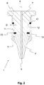
- Figure 1 shows a partially sectioned view of a spinneret 13 for an air-jet spinning machine.
- the spinneret 13 has an inlet opening 16, which can be formed, for example, by a separate fiber guide element 20 and through which the fiber material to be spun and usually present as a stretched sliver enters the so-called vortex chamber 15 of the spinning station, in which the actual spinning process takes place.
- the stretching is usually carried out by a (not shown) upstream of the fiber guide element 20 of the corresponding spinning unit of the air-jet spinning machine (which usually comprises a large number of spinning units, which in turn each have a spinneret 13 and a drafting unit), from which the drawn fiber sliver is also With the help of a pair of take-off rollers, also not shown (alternatively, the take-off can also be done by other means, e.g. a yarn storage roll).
- the fiber material After the fiber material has passed the fiber guiding element 20, it reaches the active area of several air nozzles 18, which usually open tangentially into the vortex chamber 15 and which can be present, for example, as bores within a vortex chamber wall 14. If this is done during the spinning operation via a corresponding If an overpressure is applied to the supply line (not shown) opening into an air duct 21, for example, a vortex air flow arises which flows around the area of a yarn forming element 1 protruding into the vortex chamber 15 or its outer surface 17 (at least some of the air introduced finally leaves the vortex chamber 15 again via a corresponding air outlet 19).
- multi-part yarn-forming elements 1 which consist of a base body 6 and a spinning point 4 connected to it. In these cases, however, the connection is always made with the aid of screw connections or a press fit that cannot be released.
- the present invention now proposes realizing the base body 6 and spinning tip 4 with the aid of at least one snap connection.
- the base body 6 can have a recess, preferably an annular groove 12, which is used to receive a snap ring 22.
- a sleeve 10 is provided, which likewise has a recess (preferably in the form of an annular groove 12) in the area of its inner wall 11. If the sleeve 10 is now fitted with the in Figure 3 The opening 9, which can be seen, is pushed over the spinning tip 4 and then over the base body 6, so the snap ring 22 engages in the annular groove 12 of the sleeve 10 in the intended end position of the sleeve 10. The snap connection is thus established, the spinning tip 4 and the base body 6 are connected.
- the opening 9 mentioned can be designed conically so that the wall thickness D of the sleeve 10 increases gradually starting from the opening 9.
- a sealing ring 23 is preferably present between the spinning tip 4 and the base body 6, which prevents air from escaping from the side between the base body 6 and the spinning tip 4.
Landscapes
- Engineering & Computer Science (AREA)
- Mechanical Engineering (AREA)
- Textile Engineering (AREA)
- Spinning Or Twisting Of Yarns (AREA)
Description
- Die vorliegende Erfindung betrifft ein Garnbildungselement für eine Luftspinnmaschine, die der Herstellung eines Garns aus einem Faserverband mit Hilfe einer Wirbelluftströmung dient, wobei das Garnbildungselement eine Spinnspitze mit einer Einlassöffnung besitzt, in deren Bereich mit Hilfe der Wirbelluftströmung ein Garn erzeugbar ist, wobei das Garnbildungselement einen mit der Spinnspitze verbundenen Grundkörper aufweist, und wobei das Garnbildungselement einen Abzugskanal für ein im Bereich der Spinnspitze hergestelltes Garn aufweist, der sich durch die Spinnspitze und den Grundkörper erstreckt und in einem Auslass mündet, über den das im Bereich der Spinnspitze hergestellte Garn aus dem Garnbildungselement austreten kann.
- Ferner wird eine Spinndüse für eine Luftspinnmaschine vorgeschlagen, die der Herstellung eines Garns aus einem Faserverband mit Hilfe einer Wirbelluftströmung dient, wobei die Spinndüse eine von einer Wirbelkammerwandung teilweise umgebene Wirbelkammer mit einer Einlaufmündung für einen Faserverband und ein sich zumindest teilweise in die Wirbelkammer erstreckendes Garnbildungselement aufweist, wobei der Wirbelkammer in Richtung einer äußeren Oberfläche des Garnbildungselements ausgerichtete Luftdüsen zugeordnet sind, über die Luft in die Wirbelkammer einbringbar ist, um dem Faserverband im Bereich einer Einlassöffnung des Garnbildungselements eine Drehung zu erteilen, und wobei das Garnbildungselement einen an die Einlassöffnung angrenzenden Abzugskanal aufweist, über den das Garn aus der Wirbelkammer abziehbar ist.
- Ein entsprechend aus Grundkörper und damit verbundener Spinnspitze bestehendes Garnbildungselement ist beispielsweise aus der
10 2011 053 837 A1 DE 103 33 411 A1 oder derEP 3 012 362 A2 bekannt. Die hierin beschriebene Spinndüse enthält ein in eine Wirbelkammer mündendes Garnbildungselement mit einem Abzugskanal für das in der Wirbelkammer produzierte Garn, wobei die luftspinntypische Drehung der zu verspinnenden Fasern des Faserverbands um einen nichtgedrehten Faserkern im Bereich der Einlassöffnung der Spinnspitze erfolgt. Eine weitere Ausführung mit mehrteiligem Garnführungselement ist beispielsweise in derEP 2 573 219 A2 gezeigt. - Zwar ist durch die Trennung des Garnbildungselements in Grundkörper und Spinnspitze bereits eine Anpassung der Luftspinnmaschine an unterschiedliche Fasermaterialien möglich. Auch kann die einem gewissen Verscheiß unterworfene Spinnspitze ersetzt werden, ohne das gesamte Garnbildungselement austauschen zu müssen. Dennoch besteht auch weiterhin der Bedarf, die im Stand der Technik bekannten Garnbildungselemente hinsichtlich ihrer Wartungs- bzw. Anpassungsfähigkeit an das jeweils vorliegende Fasermaterial zu verbessern.
- Aufgabe der vorliegenden Erfindung ist es daher, ein Garnbildungselement sowie eine damit ausgerüstete Spinndüse für eine Luftspinnmaschine vorzuschlagen, die dieser Forderung Rechnung tragen.
- Die Aufgabe wird gelöst durch ein Garnbildungselement sowie eine Spinndüse mit den Merkmalen der unabhängigen Patentansprüche.
- Erfindungsgemäß zeichnet sich das Garnbildungselement nun dadurch aus, dass die Spinnspitze und der Grundkörper mit Hilfe zumindest einer Schnappverbindung miteinander verbunden sind. An dieser Stelle sei darauf hingewiesen, dass der Grundkörper ein oder mehrteilig ausgebildet sein kann. Gleiches gilt für die Spinnspitze. Insbesondere handelt es sich bei der Spinnspitze um den Abschnitt des Garnbildungselements, der die genannte Einlassöffnung umfasst, während der Grundkörper denjenigen Abschnitt bildet, der den genannten Auslass für das Garn aufweist. In jedem Fall handelt es sich bei dem Grundkörper und der Spinnspitze um separate Einheiten des Garnbildungselements, die mit Hilfe einer oder mehrerer Schnappverbindungen miteinander verbunden sind.
- Bei einer Schnappverbindung im Sinne der Erfindung handelt es sich um eine Verbindung, die ein oder mehrere Funktionselemente zum lösbaren formschlüssigen Verbinden von Spinnspitze und Grundkörper umfasst. Bei der Verbindung von Spinnspitze und Grundkörper verformt sich wenigstens ein Funktionselement elastisch und greift schließlich in ein korrespondierendes weiteres Funktionselement ein. Bei den Funktionselementen kann es sich beispielsweise um elastische Haken- oder Klipselemente handeln, die beim Verbinden in ein korrespondierendes Funktionselement in Form einer Vertiefungen oder Hinterschneidung eingreifen. Ebenso kann als Funktionselement eine Feder zum Einsatz kommen, die eine Kugel oder ein sonstiges Element in eine definierte Richtung mit einer Kraft beaufschlagt. Im Übrigen können ein oder mehrere der vorhandenen Funktionselemente der Schnappverbindung Teil des Grundkörpers sein. Zumindest ein Funktionselement wird durch eine unten noch näher beschriebene erfindungsgemäße Hülse gebildet.
- In jedem Fall liegt nach dem Verbinden ein Formschluss zwischen wenigstens zwei Funktionselementen der Schnappverbindung vor, der durch Auseinanderziehen von Spinnspitze und Grundkörper wieder gelöst werden kann.
- Die Spinnspitze, die während des Spinnbetriebs einer erhöhten mechanischen Belastung durch die an ihrer Oberfläche vorbeiziehenden Fasern ausgesetzt ist, kann hierdurch auf einfache Weise durch eine neue Spinnspitze ersetzt werden.
- Insbesondere sollte die Schnappverbindung derart ausgebildet sein, dass Spinnspitze und Grundkörper manuell und ohne Einsatz eines Werkzeugs voneinander getrennt werden können.
- Insbesondere sollte die Schnappverbindung zudem derart ausgebildet sein, dass die Trennung dadurch erfolgt, dass Spinnspitze und Grundkörper in einer kolinear zu einer Längsachse des Abzugskanals verlaufenden Richtung auseinandergezogen werden. Die Verbindung erfolgt in diesem Fall vorzugsweise dadurch, dass die genannten Abschnitte des Garnbildungselements in der genannten Richtung aufeinander zubewegt werden, bis die Schnappverbindung einrastet.
- Ebenso bringt es Vorteile mit sich, wenn die Schnappverbindung ohne Einsatz eines Werkzeugs herstellbar und anschließend ohne Beschädigung der Bauteile des Garnbildungselements wieder lösbar ist.
- Des Weiteren ist es vorteilhaft, wenn die Schnappverbindung ein Funktionselement in Form eines Sprengrings umfasst. Bei einem Sprengring handelt es sich um einen Sicherungsring mit einer Unterbrechung in Umfangsrichtung. Die grundlegende Form eines Sprengrings ist in
Figur 3 (Bezugszeichen 22) gezeigt. Durch die Unterbrechung in Umfangsrichtung ist es möglich, den Sprengring durch radial auf den Sprengring ausgeübte Kraft soweit zu verformen, dass sich die durch die Unterbrechung vorhandenen Enden berühren. Der Durchmesser wird hierdurch verringert. Besitzt nun beispielsweise der Grundkörper im Bereich einer äußeren Oberfläche eine Vertiefung (z. B. in Form einer Ringnut), in der sich der Sprengring befindet, so wird dieser in radialer Richtung zusammengedrückt, wenn die im Folgenden noch näher erläuterte Hülse über den Bereich des Grundkörpers geschoben wird, der den Sprengring aufweist. Hat die Hülse ihre Endstellung bezüglich des Grundkörpers erreicht (die der Stellung entspricht, die sie nach dem Einbau in eine Spinnmaschine aufweisen soll), so kann der Sprengring wieder seine ursprüngliche Form annehmen, vorausgesetzt natürlich, die Hülse besitzt eine innenliegende Vertiefung im Bereich einer innenliegenden Oberfläche, in die der Sprengring einschnappen bzw. einrasten kann. - Erfindungsgemäß ist vorgesehen, dass die Spinnspitze mit Hilfe einer Hülse am Grundkörper gehalten ist, wobei die Schnappverbindung die Hülse und damit die Spinnspitze am Grundkörper hält. Die Hülse ist in diesem Fall Teil der Schnappverbindung und weist vorzugsweise eine, insbesondere ringförmig ausgebildete, Vertiefung im Bereich einer Innenfläche auf, in die der Sprengring einrastet, wenn die Hülse über die Spinnspitze und schließlich über einen Teil des Grundkörpers geschoben wird. Die Hülse besitzt vorzugsweise eine erste kreisförmige Öffnung, durch die ein Abschnitt des Grundkörpers ragt und eine zweite kreisförmig Öffnung, durch die die Spinnspitze ragt. Die erste Öffnung hat vorzugsweise einen größeren Durchmesser als die zweite Öffnung.
- Insbesondere sollte die Hülse im Bereich der zweiten Öffnung eine Ringschulter aufweiset (d. h. der Innendurchmesser der Hülse sollte sich ausgehend von der zweiten Öffnung in Richtung der ersten Öffnung vergrößern). Weist auch die Spinnspitze eine korrespondierende Ringschulter auf, so kann die Hülse zwar über die Spinnspitze geschoben werden. Die Spinnspitze hat jedoch in diesem Fall einen Außendurchmesser im Bereich ihrer Ringschulter, der größer ist als der Innendurchmesser der zweiten Öffnung. Die Hülse ist in diesem Fall geeignet, die Spinnspitze am Grundkörper zu halten, da die Spinnspitze nicht vollständig durch die Hülse hindurchtreten kann.
- Vorzugsweise liegt die Spinnspitze direkt oder unter Zwischenschaltung einer Ringdichtung an dem Grundkörper an, wenn die Hülse vollständig auf den Grundkörper aufgeschoben ist.
- Zudem sollten die Hülse und/oder die Spinnspitze rotationssymmetrisch ausgebildet sein. Wird die Hülse beim Zusammenbau über die Spinnspitze und schließlich über einen Abschnitt des Grundkörpers geschoben, so müssen die Spinnspitze und die Hülse gegenüber dem Grundkörper sowie die Hülse gegenüber der Spinnspitze in Umfangsrichtung der genannten Öffnungen der Hülse nicht in einem bestimmten Drehwinkel ausgerichtet werden. Der Zusammenbau des Garnbildungselements wird hierdurch vereinfacht.
- Die oben genannten Funktionselemente der Schnappverbindung werden im Übrigen vorzugsweise durch einen Sprengring, der in einer Ringnut des Grundkörpers angeordnet ist und durch eine an der Innenseite der Hülse vorhandene Vertiefung (die vorzugsweise ebenfalls durch eine Ringnut realisiert ist) gebildet, wobei der Sprengring beim Zusammenbau des Garnbildungselements in die Vertiefung der Hülse einschnappt.
- Vorteile bringt es insbesondere mit sich, wenn zum Lösen der Schnappverbindung bei ortsfest fixiertem Grundkörper eine parallel zum Abzugskanal und in Richtung der Einlassöffnung gerichtete Zugkraft auf die Spinnspitze oder die Hülse ausgeübt werden muss, die wenigstens 30 N, bevorzugt wenigstens 50 N, beträgt. Die Schnappverbindung ist in diesem Fall ausreichend sicher, um ein Lösen der Spinnspitze oder der Hülse vom Grundkörper während des Betriebs einer mit dem Garnbildungselement ausgerüsteten Luftspinnmaschine ausschließen zu können. Ebenso ist es jedoch möglich, die Schnappverbindung mit der Hand und ohne Einsatz eines Werkzeugs zu lösen, so dass die Spinnspitze vor Ort vom Bedienpersonal der Luftspinnmaschine leicht und schnell ausgetauscht werden kann.
- Insbesondere ist es von Vorteil, wenn die Hülse eine der Spinnspitze abgewandte Öffnung aufweist, wobei die Öffnung kreisförmig ausgebildet ist und wobei die radial verlaufende Wandstärke der Hülse ausgehend von der Öffnung zumindest ein Stück weit in einer kolinear zum Abzugskanal verlaufenden Richtung der Hülse zunimmt. Mit anderen Worten ist die Wandung der Hülse im Bereich der genannten Öffnung (oben bereits als "erste Öffnung" bezeichnet) vorzugsweise konisch ausgebildet. Wenn man die Hülse auf den Grundkörper aufschiebt, so bewirkt die konische Form eine Trichterwirkung und vereinfacht hierdurch das Aufschieben, ohne dass es zu einem Verkanten zwischen Hülse und Grundkörper kommt.
- Weist der Grundkörper zudem den oben beschriebenen Sprengring auf, so wird auch das Schieben der Hülse über den Sprengring und dessen Kompression in Radialrichtung vereinfacht.
- Besonders vorteilhaft ist es, wenn die Hülse eine im Bereich einer Innenwandung der Hülse angeordnete Vertiefung, vorzugsweise in Form einer Ringnut, aufweist, in die sich der Sprengring erstreckt. Die Hülse rastet in diesem Fall beim Aufschieben auf den Grundkörper in der gewünschten Endposition am Grundkörper ein. In zusammengebautem Zustand ist der Sprengring also bevorzugt nach außen hin von einer Ringnut der Hülse und nach innen hin (d. h. in Richtung des Abzugskanals) von einer Ringnut des Grundkörpers umgeben. Beide Ringnuten bilden also einen ringförmigen Kanal, in dem sich der Sprengring befindet.
- Ebenso bringt es Vorteile mit sich, wenn der Grundkörper aus Metall, die Spinnspitze zumindest abschnittsweise aus Keramik und die Hülse aus Kunststoff gefertigt sind. Die Hülse kann in diesem Fall besonders kostengünstig hergestellt werden, wobei der Grundkörper und die Spinnspitze die notwendige Steifigkeit bzw. im Fall von Keramik die nötige Verschleißfestigkeit aufweisen.
- Des Weiteren ist es vorteilhaft, wenn zwischen der Spinnspitze und dem Grundkörper ein oder mehrere Dichtungsringe angeordnet sind. Insbesondere sollten der oder die Dichtungsringe (die aus Gummi, Kunststoff oder auch Metall bestehen können) den Abzugskanal, vorzugsweise konzentrisch, umgeben. Vorzugsweise verlaufen der oder die Dichtungsringe auch konzentrisch zu dem genannten Sprengring (falls vorhanden). In jedem Fall wird durch den oder die Dichtungsringe verhindert, dass Luft, die während des Spinnbetriebs durch den Abzugskanal strömt, seitlich zwischen Spinnspitze und Grundkörper austreten kann.
- Schließlich wird eine Spinndüse vorgeschlagen, die neben einer aus dem Stand der Technik bekannten Wirbelkammer und den für die Wirbelluftströmung beim Spinnbetrieb zuständigen Luftdüsen ein in die Wirbelkammer ragendes Garnbildungselement umfasst. Erfindungsgemäß ist das Garnbildungselement gemäß bisheriger bzw. nachfolgender Beschreibung ausgebildet.
- Weitere Vorteile der Erfindung sind in den nachfolgenden Ausführungsbeispielen beschrieben. Es zeigen, jeweils schematisch:
- Figur 1
- eine teilweise geschnittene Darstellung einer erfindungsgemäßen Spinndüse,
- Figur 2
- einen Längsschnitt eines erfindungsgemäßen Garnbildungselements,
- Figur 3
- eine Explosionsdarstellung eines erfindungsgemäßen Garnbildungselements.
-
Figur 1 zeigt eine teilweise geschnittene Darstellung einer Spinndüse 13 für eine Luftspinnmaschine. Die Spinndüse 13 besitzt eine Einlaufmündung 16, die beispielsweise durch ein separates Faserführungselement 20 gebildet sein kann und durch welche das zu verspinnende und meist als verstrecktes Faserband vorliegende Fasermaterial in die sogenannte Wirbelkammer 15 der Spinnstelle gelangt, in der wiederum der eigentliche Spinnprozess stattfindet. - Die Verstreckung übernimmt in der Regel ein dem Faserführungselement 20 vorgelagertes (nicht gezeigtes) Streckwerk der entsprechenden Spinnstelle der Luftspinnmaschine (die in der Regel eine Vielzahl von Spinnstellen umfasst, die wiederum jeweils eine Spinndüse 13 und ein Streckwerk aufweisen), aus dem das verstreckte Faserband mit Hilfe eines ebenfalls nicht gezeigten Abzugswalzenpaars abgezogen wird (alternativ kann der Abzug auch durch andere Mittel, z. B. einer Garnspeicherrolle, erfolgen).
- Nachdem das Fasermaterial das Faserführungselement 20 passiert hat, gelangt es in den Wirkbereich mehrerer, in der Regel tangential in die Wirbelkammer 15 mündenden, Luftdüsen 18, die beispielsweise als Bohrungen innerhalb einer Wirbelkammerwandung 14 vorliegen können. Werden diese während des Spinnbetriebs über eine entsprechende, z. B. in einen Luftkanal 21 mündende, Versorgungsleitung (nicht gezeigt) mit einem Überdruck beaufschlagt, so entsteht eine Wirbelluftströmung, die den eine Einlassöffnung 5 für die Fasern aufweisenden Bereich eines in die Wirbelkammer 15 ragenden Garnbildungselements 1 bzw. dessen äußere Oberfläche 17 umströmt (zumindest ein Teil der eingebrachten Luft verlässt die Wirbelkammer 15 schließlich wieder über einen entsprechenden Luftauslass 19).
- Werden die nach außen abstehenden Faserenden des Faserverbands 3 von dieser Wirbelluftströmung erfasst, so entsteht schließlich die gewünschte Drehung des Fasermaterials und im Ergebnis das gewünschte Garn 2, welches über den sich an die Einlassöffnung 5 anschließenden Abzugskanal 7 aus der Wirbelkammer 15 und letztendlich über einen Auslass 8 aus der Spinndüse 13 abgezogen werden kann.
- Neben einteiligen Garnbildungselementen 1 sind bereits mehrteilige Garnbildungselemente 1 bekannt, die aus einem Grundkörper 6 und einer damit verbundenen Spinnspitze 4 bestehen. Die Verbindung erfolgt in diesen Fällen jedoch stets mit Hilfe von Verschraubungen oder durch einen nicht mehr zu lösenden Presssitz.
- Im Gegensatz hierzu schlägt die vorliegende Erfindung nun vor, Grundkörper 6 und Spinnspitze 4 mit Hilfe zumindest einer Schnappverbindung zu realisieren.
- Eine konstruktive Möglichkeit einer derartigen Verbindung zeigen die
Figuren 2 (Schnittdarstellung) und 3 (Explosionszeichnung). - Wie diesen Figuren zu entnahmen ist, kann der Grundkörper 6 eine Vertiefung, vorzugsweise eine Ringnut 12, aufweisen, die der Aufnahme eines Sprengrings 22 dient.
- Ferner ist eine Hülse 10 vorgesehen, die ebenfalls eine Vertiefung (vorzugsweise in Form einer Ringnut 12) im Bereich ihrer Innenwandung 11 aufweist. Wird die Hülse 10 nun mit der in
Figur 3 zu sehenden Öffnung 9 über die Spinnspitze 4 und anschließend über den Grundkörper 6 geschoben, so rastet der Sprengring 22 in der vorgesehenen Endstellung der Hülse 10 in die Ringnut 12 der Hülse 10 ein. Die Schnappverbindung ist damit hergestellt, Spinnspitze 4 und Grundkörper 6 sind verbunden. - Um das Aufschieben und insbesondere das Überziehen der Hülse 10 über den Sprengring 22 zu vereinfachen, kann die genannte Öffnung 9 konisch ausgebildet sein, so dass die Wandstärke D der Hülse 10 ausgehend von der Öffnung 9 allmählich zunimmt.
- Vorzugsweise ist zwischen der Spinnspitze 4 und dem Grundkörper 6 ein Dichtungsring 23 vorhanden, der ein seitliches Austreten von Luft zwischen Grundkörper 6 und Spinnspitze 4 verhindert.
- Auch können anstelle des Sprengrings 22 andere Abschnitte, beispielsweise in Form von Rastelementen, vorhanden sein, die z. B. Teil des Grundkörpers 6 und/oder der Hülse 10 sein können.
- Die vorliegende Erfindung ist nicht auf die dargestellten und beschriebenen Ausführungsbeispiele beschränkt. Abwandlungen im Rahmen der Patentansprüche sind ebenso möglich wie eine beliebige Kombination der beschriebenen Merkmale, auch wenn sie in unterschiedlichen Teilen der Beschreibung bzw. den Ansprüchen oder in unterschiedlichen Ausführungsbeispielen dargestellt und beschrieben sind, vorausgesetzt, dass kein Widerspruch zur Lehre der unabhängigen Ansprüche entsteht.
-
- 1
- Garnbildungselement
- 2
- Garn
- 3
- Faserverband
- 4
- Spinnspitze
- 5
- Einlassöffnung
- 6
- Grundkörper
- 7
- Abzugskanal
- 8
- Auslass
- 9
- Öffnung der Hülse
- 10
- Hülse
- 11
- Innenwandung der Hülse
- 12
- Ringnut
- 13
- Spinndüse
- 14
- Wirbelkammerwandung
- 15
- Wirbelkammer
- 16
- Einlaufmündung der Spinndüse
- 17
- äußerer Oberfläche des Garnbildungselements
- 18
- Luftdüse
- 19
- Luftauslass
- 20
- Faserführungselement
- 21
- Luftkanal
- 22
- Sprengring
- 23
- Dichtungsring
- D
- Wandstärke der Hülse
Claims (9)
- Garnbildungselement (1) für eine Luftspinnmaschine, die der Herstellung eines Garns (2) aus einem Faserverband (3) mit Hilfe einer Wirbelluftströmung dient,- wobei das Garnbildungselement (1) eine Spinnspitze (4) mit einer Einlassöffnung (5) für Fasern des Faserverbands (3) besitzt,- wobei das Garnbildungselement (1) einen mit der Spinnspitze (4) verbundenen Grundkörper (6) aufweist, und- wobei das Garnbildungselement (1) einen Abzugskanal (7) für ein im Bereich der Spinnspitze (4) hergestelltes Garn (2) aufweist, der sich durch die Spinnspitze (4) und den Grundkörper (6) erstreckt und in einem Auslass (8) mündet, über den das im Bereich der Spinnspitze (4) hergestellte Garn (2) aus dem Garnbildungselement (1) austreten kann,wobei die Spinnspitze (4) und der Grundkörper (6) mit Hilfe zumindest einer Schnappverbindung miteinander verbunden sind, wobei die Spinnspitze (4) mit Hilfe einer Hülse (10) am Grundkörper (6) gehalten ist, dadurch gekennzeichnet, dass die Schnappverbindung die Hülse (10) und damit die Spinnspitze (4) am Grundkörper (6) hält.
- Garnbildungselement (1) gemäß dem vorangegangenen Anspruch, dadurch gekennzeichnet, dass die Schnappverbindung ohne Einsatz eines Werkzeugs herstellbar und anschließend ohne Beschädigung der Bauteile des Garnbildungselements (1) und ebenfalls ohne Einsatz eines Werkzeugs wieder lösbar ist.
- Garnbildungselement (1) gemäß einem der vorangegangenen Ansprüche, dadurch gekennzeichnet, dass die Schnappverbindung einen Sprengring (22) umfasst, der vorzugsweise in einer Ringnut (12) des Grundkörpers (6) gehalten ist.
- Garnbildungselement (1) gemäß einem der vorangegangenen Ansprüche, dadurch gekennzeichnet, dass zum Lösen der Schnappverbindung bei ortsfest fixiertem Grundkörper (6) eine parallel zum Abzugskanal (7) und in Richtung der Einlassöffnung (5) gerichtete Zugkraft auf die Spinnspitze (4) oder die Hülse (10) ausgeübt werden muss, die wenigstens 30 N, bevorzugt wenigstens 50 N, beträgt.
- Garnbildungselement (1) gemäß einem der vorangegangenen Ansprüche, dadurch gekennzeichnet, dass die Hülse (10) eine der Spinnspitze (4) abgewandte Öffnung (9) aufweist, wobei die Öffnung (9) kreisförmig ausgebildet ist, und wobei die radial verlaufende Wandstärke (D) der Hülse (10) ausgehend von der Öffnung (9) zumindest ein Stück weit in einer kolinear zum Abzugskanal (7) verlaufenden Richtung der Hülse (10) zunimmt.
- Garnbildungselement (1) gemäß einem der Ansprüche 3 bis 5, dadurch gekennzeichnet, dass die Hülse (10) eine im Bereich einer Innenwandung (11) der Hülse (10) angeordnete Vertiefung, vorzugsweise in Form einer Ringnut (12), aufweist, in die sich der Sprengring (22) erstreckt.
- Garnbildungselement (1) gemäß einem der vorangegangenen Ansprüche, dadurch gekennzeichnet, dass der Grundkörper (6) aus Metall, die Spinnspitze (4) zumindest abschnittsweise aus Keramik und die Hülse (10) aus Kunststoff gefertigt ist.
- Garnbildungselement (1) gemäß einem der vorangegangenen Ansprüche, dadurch gekennzeichnet, dass zwischen der Spinnspitze (4) und dem Grundkörper (6) ein oder mehrere Dichtungsringe (23) angeordnet sind.
- Spinndüse (13) für eine Luftspinnmaschine, die der Herstellung eines Garns (2) aus einem Faserverband (3) mit Hilfe einer Wirbelluftströmung dient,- wobei die Spinndüse (13) eine von einer Wirbelkammerwandung (14) teilweise umgebene Wirbelkammer (15) mit einer Einlaufmündung (16) für einen Faserverband (3) und ein sich zumindest teilweise in die Wirbelkammer (15) erstreckendes Garnbildungselement (1) aufweist,- wobei der Wirbelkammer (15) Luftdüsen (18) zugeordnet sind, über die Luft in die Wirbelkammer (15) einbringbar ist, um dem Faserverband (3) im Bereich einer Einlassöffnung (5) des Garnbildungselements (1) eine Drehung zu erteilen, und- wobei das Garnbildungselement (1) einen an die Einlassöffnung (5) angrenzenden Abzugskanal (7) aufweist, über den das Garn (2) aus der Wirbelkammer (15) abziehbar ist,dadurch gekennzeichnet,
dass das Garnbildungselement (1) gemäß einem der vorangegangenen Ansprüche ausgebildet ist.
Applications Claiming Priority (1)
| Application Number | Priority Date | Filing Date | Title |
|---|---|---|---|
| DE102016116693.6A DE102016116693A1 (de) | 2016-09-07 | 2016-09-07 | Garnbildungselement und Spinndüse für eine Luftspinnmaschine |
Publications (2)
| Publication Number | Publication Date |
|---|---|
| EP3293294A1 EP3293294A1 (de) | 2018-03-14 |
| EP3293294B1 true EP3293294B1 (de) | 2020-10-28 |
Family
ID=59799274
Family Applications (1)
| Application Number | Title | Priority Date | Filing Date |
|---|---|---|---|
| EP17189446.2A Active EP3293294B1 (de) | 2016-09-07 | 2017-09-05 | Garnbildungselement und spinndüse für eine luftspinnmaschine |
Country Status (4)
| Country | Link |
|---|---|
| EP (1) | EP3293294B1 (de) |
| JP (1) | JP7161283B2 (de) |
| CN (1) | CN107794607B (de) |
| DE (1) | DE102016116693A1 (de) |
Families Citing this family (2)
| Publication number | Priority date | Publication date | Assignee | Title |
|---|---|---|---|---|
| CN108318972B (zh) * | 2018-03-14 | 2019-12-03 | 北京宏源四方科技开发有限公司 | 一种光纤连接密封承压接头 |
| EP4043625A1 (de) | 2021-02-10 | 2022-08-17 | Saurer Intelligent Technology AG | Garnbildungselement |
Family Cites Families (8)
| Publication number | Priority date | Publication date | Assignee | Title |
|---|---|---|---|---|
| DE10333411A1 (de) | 2003-07-15 | 2005-02-03 | Wilhelm Stahlecker Gmbh | Vorrichtung zum Herstellen eines gesponnenen Fadens aus einem Stapelfaserverband |
| DE102008050874A1 (de) * | 2008-09-29 | 2010-04-01 | Wilhelm Stahlecker Gmbh | Luftdüsenspinnaggregat mit spindelförmigem Bauteil |
| DE102011053810A1 (de) * | 2011-09-21 | 2013-05-16 | Maschinenfabrik Rieter Ag | Garnbildungselement für eine Spinnstelle einer Luftspinnmaschine sowie Verfahren zur Vorbereitung eines Anspinnvorgangs an einer Luftspinnmaschine |
| DE102011053837A1 (de) | 2011-09-21 | 2013-03-21 | Maschinenfabrik Rieter Ag | Spinnspitze für eine Hohlspindel einer Luftspinnmaschine |
| JP2013067897A (ja) * | 2011-09-21 | 2013-04-18 | Murata Mach Ltd | 紡績機 |
| DE102012110315A1 (de) | 2012-10-29 | 2014-04-30 | Maschinenfabrik Rieter Ag | Garnbildungselement für eine Luftspinnmaschine mit einem Einsatz sowie damit ausgerüstete Spinndüse |
| CN102912491B (zh) * | 2012-11-02 | 2015-08-12 | 东华大学 | 一种涡流管内部结构为三段式的喷气涡流纺喷嘴装置 |
| JP6394954B2 (ja) * | 2014-09-30 | 2018-09-26 | 村田機械株式会社 | 中空ガイド軸体、空気紡績装置、及び繊維機械 |
-
2016
- 2016-09-07 DE DE102016116693.6A patent/DE102016116693A1/de not_active Withdrawn
-
2017
- 2017-09-05 EP EP17189446.2A patent/EP3293294B1/de active Active
- 2017-09-06 CN CN201710797867.8A patent/CN107794607B/zh active Active
- 2017-09-07 JP JP2017172182A patent/JP7161283B2/ja active Active
Non-Patent Citations (1)
| Title |
|---|
| None * |
Also Published As
| Publication number | Publication date |
|---|---|
| CN107794607A (zh) | 2018-03-13 |
| JP2018040102A (ja) | 2018-03-15 |
| CN107794607B (zh) | 2021-08-10 |
| DE102016116693A1 (de) | 2018-03-08 |
| EP3293294A1 (de) | 2018-03-14 |
| JP7161283B2 (ja) | 2022-10-26 |
Similar Documents
| Publication | Publication Date | Title |
|---|---|---|
| EP1786961A1 (de) | Luftdüsenspinnvorrichtung | |
| EP3048191B1 (de) | Spinndüse einer luftspinnmaschine sowie verfahren zum öffnen derselben | |
| EP2454402A1 (de) | Bauteil für eine luftdüsenspinnvorrichtung | |
| EP1845180B1 (de) | Spindelförmiges Bauteil für eine Luftdüsenspinnvorrichtung mit einem Injektionskanal | |
| EP2730685B1 (de) | Garnbildungselement für eine Luftspinnmaschine mit einem Einsatz sowie damit ausgerüstete Spinndüse | |
| EP3309281B1 (de) | Faserführungselement für eine spinndüse einer luftspinnmaschine sowie verfahren zum betrieb einer luftspinnmaschine | |
| DE102012108613A1 (de) | Spinnstelle einer Vorspinnmaschine | |
| EP2772572B1 (de) | Spinnstelle zur Herstellung eines Garns | |
| WO2017187293A1 (de) | Luftspinnmaschine sowie verfahren zur herstellung eines garns | |
| EP3293294B1 (de) | Garnbildungselement und spinndüse für eine luftspinnmaschine | |
| DE102011053837A1 (de) | Spinnspitze für eine Hohlspindel einer Luftspinnmaschine | |
| EP2573219A2 (de) | Garnbildungselement für eine Spinnstelle einer Luftspinnmaschine sowie Verfahren zur Vorbereitung eines Anspinnvorgangs an einer Luftspinnmaschine | |
| WO2018228864A1 (de) | Arbeitsstelle einer luftspinnmaschine sowie verfahren zum öffnen einer spinndüse | |
| WO2005047577A1 (de) | Luftdüsen-spinnvorrichtung | |
| WO2018087054A1 (de) | Spinndüse für eine luftspinnmaschine sowie verfahren zum betrieb einer solchen | |
| EP3155151B1 (de) | Spinndüse für eine luftspinnmaschine sowie luftspinnmaschine mit einer entsprechenden spinndüse | |
| DE102005022686A1 (de) | Vorrichtung zum Herstellen eines gesponnenen Fadens | |
| EP3663445A1 (de) | Spinndüse sowie verfahren zum reinigen derselben | |
| EP3464691B1 (de) | Garnbildungselement für eine vorspinnmaschine sowie damit ausgerüstete vorspinnmaschine | |
| DE102014112360A1 (de) | Garnbildungselement für eine Spinndüse einer Luftspinnmaschine, Luftspinnmaschine sowie Verfahren zum Betrieb einer solchen | |
| EP3744880A1 (de) | Drallelement für eine spinndüse einer luftspinnmaschine sowie spinndüse | |
| WO2005040466A1 (de) | Vorrichtung zum herstellen eines gesponnenen fadens aus einem stapelfaserverband | |
| DE19819850A1 (de) | Spinnflügel für eine Vorspinnmaschine |
Legal Events
| Date | Code | Title | Description |
|---|---|---|---|
| PUAI | Public reference made under article 153(3) epc to a published international application that has entered the european phase |
Free format text: ORIGINAL CODE: 0009012 |
|
| STAA | Information on the status of an ep patent application or granted ep patent |
Free format text: STATUS: THE APPLICATION HAS BEEN PUBLISHED |
|
| AK | Designated contracting states |
Kind code of ref document: A1 Designated state(s): AL AT BE BG CH CY CZ DE DK EE ES FI FR GB GR HR HU IE IS IT LI LT LU LV MC MK MT NL NO PL PT RO RS SE SI SK SM TR |
|
| AX | Request for extension of the european patent |
Extension state: BA ME |
|
| STAA | Information on the status of an ep patent application or granted ep patent |
Free format text: STATUS: REQUEST FOR EXAMINATION WAS MADE |
|
| 17P | Request for examination filed |
Effective date: 20180912 |
|
| RBV | Designated contracting states (corrected) |
Designated state(s): AL AT BE BG CH CY CZ DE DK EE ES FI FR GB GR HR HU IE IS IT LI LT LU LV MC MK MT NL NO PL PT RO RS SE SI SK SM TR |
|
| GRAP | Despatch of communication of intention to grant a patent |
Free format text: ORIGINAL CODE: EPIDOSNIGR1 |
|
| STAA | Information on the status of an ep patent application or granted ep patent |
Free format text: STATUS: GRANT OF PATENT IS INTENDED |
|
| INTG | Intention to grant announced |
Effective date: 20200608 |
|
| GRAS | Grant fee paid |
Free format text: ORIGINAL CODE: EPIDOSNIGR3 |
|
| GRAA | (expected) grant |
Free format text: ORIGINAL CODE: 0009210 |
|
| STAA | Information on the status of an ep patent application or granted ep patent |
Free format text: STATUS: THE PATENT HAS BEEN GRANTED |
|
| AK | Designated contracting states |
Kind code of ref document: B1 Designated state(s): AL AT BE BG CH CY CZ DE DK EE ES FI FR GB GR HR HU IE IS IT LI LT LU LV MC MK MT NL NO PL PT RO RS SE SI SK SM TR |
|
| REG | Reference to a national code |
Ref country code: GB Ref legal event code: FG4D Free format text: NOT ENGLISH |
|
| REG | Reference to a national code |
Ref country code: CH Ref legal event code: EP |
|
| REG | Reference to a national code |
Ref country code: AT Ref legal event code: REF Ref document number: 1328319 Country of ref document: AT Kind code of ref document: T Effective date: 20201115 |
|
| REG | Reference to a national code |
Ref country code: DE Ref legal event code: R096 Ref document number: 502017007907 Country of ref document: DE |
|
| REG | Reference to a national code |
Ref country code: IE Ref legal event code: FG4D Free format text: LANGUAGE OF EP DOCUMENT: GERMAN |
|
| REG | Reference to a national code |
Ref country code: NL Ref legal event code: MP Effective date: 20201028 |
|
| PG25 | Lapsed in a contracting state [announced via postgrant information from national office to epo] |
Ref country code: NO Free format text: LAPSE BECAUSE OF FAILURE TO SUBMIT A TRANSLATION OF THE DESCRIPTION OR TO PAY THE FEE WITHIN THE PRESCRIBED TIME-LIMIT Effective date: 20210128 Ref country code: NL Free format text: LAPSE BECAUSE OF FAILURE TO SUBMIT A TRANSLATION OF THE DESCRIPTION OR TO PAY THE FEE WITHIN THE PRESCRIBED TIME-LIMIT Effective date: 20201028 Ref country code: PT Free format text: LAPSE BECAUSE OF FAILURE TO SUBMIT A TRANSLATION OF THE DESCRIPTION OR TO PAY THE FEE WITHIN THE PRESCRIBED TIME-LIMIT Effective date: 20210301 Ref country code: RS Free format text: LAPSE BECAUSE OF FAILURE TO SUBMIT A TRANSLATION OF THE DESCRIPTION OR TO PAY THE FEE WITHIN THE PRESCRIBED TIME-LIMIT Effective date: 20201028 Ref country code: FI Free format text: LAPSE BECAUSE OF FAILURE TO SUBMIT A TRANSLATION OF THE DESCRIPTION OR TO PAY THE FEE WITHIN THE PRESCRIBED TIME-LIMIT Effective date: 20201028 Ref country code: GR Free format text: LAPSE BECAUSE OF FAILURE TO SUBMIT A TRANSLATION OF THE DESCRIPTION OR TO PAY THE FEE WITHIN THE PRESCRIBED TIME-LIMIT Effective date: 20210129 |
|
| REG | Reference to a national code |
Ref country code: LT Ref legal event code: MG4D |
|
| PG25 | Lapsed in a contracting state [announced via postgrant information from national office to epo] |
Ref country code: ES Free format text: LAPSE BECAUSE OF FAILURE TO SUBMIT A TRANSLATION OF THE DESCRIPTION OR TO PAY THE FEE WITHIN THE PRESCRIBED TIME-LIMIT Effective date: 20201028 Ref country code: BG Free format text: LAPSE BECAUSE OF FAILURE TO SUBMIT A TRANSLATION OF THE DESCRIPTION OR TO PAY THE FEE WITHIN THE PRESCRIBED TIME-LIMIT Effective date: 20210128 Ref country code: LV Free format text: LAPSE BECAUSE OF FAILURE TO SUBMIT A TRANSLATION OF THE DESCRIPTION OR TO PAY THE FEE WITHIN THE PRESCRIBED TIME-LIMIT Effective date: 20201028 Ref country code: IS Free format text: LAPSE BECAUSE OF FAILURE TO SUBMIT A TRANSLATION OF THE DESCRIPTION OR TO PAY THE FEE WITHIN THE PRESCRIBED TIME-LIMIT Effective date: 20210228 Ref country code: PL Free format text: LAPSE BECAUSE OF FAILURE TO SUBMIT A TRANSLATION OF THE DESCRIPTION OR TO PAY THE FEE WITHIN THE PRESCRIBED TIME-LIMIT Effective date: 20201028 Ref country code: SE Free format text: LAPSE BECAUSE OF FAILURE TO SUBMIT A TRANSLATION OF THE DESCRIPTION OR TO PAY THE FEE WITHIN THE PRESCRIBED TIME-LIMIT Effective date: 20201028 |
|
| PG25 | Lapsed in a contracting state [announced via postgrant information from national office to epo] |
Ref country code: HR Free format text: LAPSE BECAUSE OF FAILURE TO SUBMIT A TRANSLATION OF THE DESCRIPTION OR TO PAY THE FEE WITHIN THE PRESCRIBED TIME-LIMIT Effective date: 20201028 |
|
| REG | Reference to a national code |
Ref country code: DE Ref legal event code: R097 Ref document number: 502017007907 Country of ref document: DE |
|
| PG25 | Lapsed in a contracting state [announced via postgrant information from national office to epo] |
Ref country code: LT Free format text: LAPSE BECAUSE OF FAILURE TO SUBMIT A TRANSLATION OF THE DESCRIPTION OR TO PAY THE FEE WITHIN THE PRESCRIBED TIME-LIMIT Effective date: 20201028 Ref country code: SM Free format text: LAPSE BECAUSE OF FAILURE TO SUBMIT A TRANSLATION OF THE DESCRIPTION OR TO PAY THE FEE WITHIN THE PRESCRIBED TIME-LIMIT Effective date: 20201028 Ref country code: EE Free format text: LAPSE BECAUSE OF FAILURE TO SUBMIT A TRANSLATION OF THE DESCRIPTION OR TO PAY THE FEE WITHIN THE PRESCRIBED TIME-LIMIT Effective date: 20201028 Ref country code: CZ Free format text: LAPSE BECAUSE OF FAILURE TO SUBMIT A TRANSLATION OF THE DESCRIPTION OR TO PAY THE FEE WITHIN THE PRESCRIBED TIME-LIMIT Effective date: 20201028 Ref country code: RO Free format text: LAPSE BECAUSE OF FAILURE TO SUBMIT A TRANSLATION OF THE DESCRIPTION OR TO PAY THE FEE WITHIN THE PRESCRIBED TIME-LIMIT Effective date: 20201028 Ref country code: SK Free format text: LAPSE BECAUSE OF FAILURE TO SUBMIT A TRANSLATION OF THE DESCRIPTION OR TO PAY THE FEE WITHIN THE PRESCRIBED TIME-LIMIT Effective date: 20201028 |
|
| PG25 | Lapsed in a contracting state [announced via postgrant information from national office to epo] |
Ref country code: DK Free format text: LAPSE BECAUSE OF FAILURE TO SUBMIT A TRANSLATION OF THE DESCRIPTION OR TO PAY THE FEE WITHIN THE PRESCRIBED TIME-LIMIT Effective date: 20201028 |
|
| PLBE | No opposition filed within time limit |
Free format text: ORIGINAL CODE: 0009261 |
|
| STAA | Information on the status of an ep patent application or granted ep patent |
Free format text: STATUS: NO OPPOSITION FILED WITHIN TIME LIMIT |
|
| 26N | No opposition filed |
Effective date: 20210729 |
|
| PG25 | Lapsed in a contracting state [announced via postgrant information from national office to epo] |
Ref country code: AL Free format text: LAPSE BECAUSE OF FAILURE TO SUBMIT A TRANSLATION OF THE DESCRIPTION OR TO PAY THE FEE WITHIN THE PRESCRIBED TIME-LIMIT Effective date: 20201028 |
|
| PG25 | Lapsed in a contracting state [announced via postgrant information from national office to epo] |
Ref country code: SI Free format text: LAPSE BECAUSE OF FAILURE TO SUBMIT A TRANSLATION OF THE DESCRIPTION OR TO PAY THE FEE WITHIN THE PRESCRIBED TIME-LIMIT Effective date: 20201028 |
|
| REG | Reference to a national code |
Ref country code: CH Ref legal event code: PL |
|
| REG | Reference to a national code |
Ref country code: BE Ref legal event code: MM Effective date: 20210930 |
|
| GBPC | Gb: european patent ceased through non-payment of renewal fee |
Effective date: 20210905 |
|
| PG25 | Lapsed in a contracting state [announced via postgrant information from national office to epo] |
Ref country code: IS Free format text: LAPSE BECAUSE OF FAILURE TO SUBMIT A TRANSLATION OF THE DESCRIPTION OR TO PAY THE FEE WITHIN THE PRESCRIBED TIME-LIMIT Effective date: 20210228 Ref country code: MC Free format text: LAPSE BECAUSE OF FAILURE TO SUBMIT A TRANSLATION OF THE DESCRIPTION OR TO PAY THE FEE WITHIN THE PRESCRIBED TIME-LIMIT Effective date: 20201028 |
|
| PG25 | Lapsed in a contracting state [announced via postgrant information from national office to epo] |
Ref country code: LU Free format text: LAPSE BECAUSE OF NON-PAYMENT OF DUE FEES Effective date: 20210905 Ref country code: IE Free format text: LAPSE BECAUSE OF NON-PAYMENT OF DUE FEES Effective date: 20210905 Ref country code: GB Free format text: LAPSE BECAUSE OF NON-PAYMENT OF DUE FEES Effective date: 20210905 Ref country code: FR Free format text: LAPSE BECAUSE OF NON-PAYMENT OF DUE FEES Effective date: 20210930 Ref country code: BE Free format text: LAPSE BECAUSE OF NON-PAYMENT OF DUE FEES Effective date: 20210930 |
|
| PG25 | Lapsed in a contracting state [announced via postgrant information from national office to epo] |
Ref country code: LI Free format text: LAPSE BECAUSE OF NON-PAYMENT OF DUE FEES Effective date: 20210930 Ref country code: CH Free format text: LAPSE BECAUSE OF NON-PAYMENT OF DUE FEES Effective date: 20210930 |
|
| PG25 | Lapsed in a contracting state [announced via postgrant information from national office to epo] |
Ref country code: HU Free format text: LAPSE BECAUSE OF FAILURE TO SUBMIT A TRANSLATION OF THE DESCRIPTION OR TO PAY THE FEE WITHIN THE PRESCRIBED TIME-LIMIT; INVALID AB INITIO Effective date: 20170905 |
|
| P01 | Opt-out of the competence of the unified patent court (upc) registered |
Effective date: 20230329 |
|
| PG25 | Lapsed in a contracting state [announced via postgrant information from national office to epo] |
Ref country code: CY Free format text: LAPSE BECAUSE OF FAILURE TO SUBMIT A TRANSLATION OF THE DESCRIPTION OR TO PAY THE FEE WITHIN THE PRESCRIBED TIME-LIMIT Effective date: 20201028 |
|
| REG | Reference to a national code |
Ref country code: AT Ref legal event code: MM01 Ref document number: 1328319 Country of ref document: AT Kind code of ref document: T Effective date: 20220905 |
|
| PGFP | Annual fee paid to national office [announced via postgrant information from national office to epo] |
Ref country code: DE Payment date: 20230928 Year of fee payment: 7 |
|
| PG25 | Lapsed in a contracting state [announced via postgrant information from national office to epo] |
Ref country code: AT Free format text: LAPSE BECAUSE OF NON-PAYMENT OF DUE FEES Effective date: 20220905 |
|
| PGFP | Annual fee paid to national office [announced via postgrant information from national office to epo] |
Ref country code: IT Payment date: 20230927 Year of fee payment: 7 |
|
| PG25 | Lapsed in a contracting state [announced via postgrant information from national office to epo] |
Ref country code: MK Free format text: LAPSE BECAUSE OF FAILURE TO SUBMIT A TRANSLATION OF THE DESCRIPTION OR TO PAY THE FEE WITHIN THE PRESCRIBED TIME-LIMIT Effective date: 20201028 |