EP3290982B1 - Optical apparatus, machining apparatus, and article manufacturing method - Google Patents
Optical apparatus, machining apparatus, and article manufacturing method Download PDFInfo
- Publication number
- EP3290982B1 EP3290982B1 EP17187820.0A EP17187820A EP3290982B1 EP 3290982 B1 EP3290982 B1 EP 3290982B1 EP 17187820 A EP17187820 A EP 17187820A EP 3290982 B1 EP3290982 B1 EP 3290982B1
- Authority
- EP
- European Patent Office
- Prior art keywords
- light
- reflecting surface
- incident
- reflected
- optical
- Prior art date
- Legal status (The legal status is an assumption and is not a legal conclusion. Google has not performed a legal analysis and makes no representation as to the accuracy of the status listed.)
- Active
Links
Images





Classifications
-
- G—PHYSICS
- G02—OPTICS
- G02B—OPTICAL ELEMENTS, SYSTEMS OR APPARATUS
- G02B26/00—Optical devices or arrangements for the control of light using movable or deformable optical elements
- G02B26/08—Optical devices or arrangements for the control of light using movable or deformable optical elements for controlling the direction of light
- G02B26/10—Scanning systems
- G02B26/105—Scanning systems with one or more pivoting mirrors or galvano-mirrors
-
- B—PERFORMING OPERATIONS; TRANSPORTING
- B23—MACHINE TOOLS; METAL-WORKING NOT OTHERWISE PROVIDED FOR
- B23K—SOLDERING OR UNSOLDERING; WELDING; CLADDING OR PLATING BY SOLDERING OR WELDING; CUTTING BY APPLYING HEAT LOCALLY, e.g. FLAME CUTTING; WORKING BY LASER BEAM
- B23K26/00—Working by laser beam, e.g. welding, cutting or boring
- B23K26/02—Positioning or observing the workpiece, e.g. with respect to the point of impact; Aligning, aiming or focusing the laser beam
- B23K26/04—Automatically aligning, aiming or focusing the laser beam, e.g. using the back-scattered light
- B23K26/042—Automatically aligning the laser beam
- B23K26/043—Automatically aligning the laser beam along the beam path, i.e. alignment of laser beam axis relative to laser beam apparatus
-
- B—PERFORMING OPERATIONS; TRANSPORTING
- B23—MACHINE TOOLS; METAL-WORKING NOT OTHERWISE PROVIDED FOR
- B23K—SOLDERING OR UNSOLDERING; WELDING; CLADDING OR PLATING BY SOLDERING OR WELDING; CUTTING BY APPLYING HEAT LOCALLY, e.g. FLAME CUTTING; WORKING BY LASER BEAM
- B23K26/00—Working by laser beam, e.g. welding, cutting or boring
- B23K26/02—Positioning or observing the workpiece, e.g. with respect to the point of impact; Aligning, aiming or focusing the laser beam
- B23K26/06—Shaping the laser beam, e.g. by masks or multi-focusing
- B23K26/064—Shaping the laser beam, e.g. by masks or multi-focusing by means of optical elements, e.g. lenses, mirrors or prisms
-
- B—PERFORMING OPERATIONS; TRANSPORTING
- B23—MACHINE TOOLS; METAL-WORKING NOT OTHERWISE PROVIDED FOR
- B23K—SOLDERING OR UNSOLDERING; WELDING; CLADDING OR PLATING BY SOLDERING OR WELDING; CUTTING BY APPLYING HEAT LOCALLY, e.g. FLAME CUTTING; WORKING BY LASER BEAM
- B23K26/00—Working by laser beam, e.g. welding, cutting or boring
- B23K26/02—Positioning or observing the workpiece, e.g. with respect to the point of impact; Aligning, aiming or focusing the laser beam
- B23K26/06—Shaping the laser beam, e.g. by masks or multi-focusing
- B23K26/064—Shaping the laser beam, e.g. by masks or multi-focusing by means of optical elements, e.g. lenses, mirrors or prisms
- B23K26/0643—Shaping the laser beam, e.g. by masks or multi-focusing by means of optical elements, e.g. lenses, mirrors or prisms comprising mirrors
-
- B—PERFORMING OPERATIONS; TRANSPORTING
- B23—MACHINE TOOLS; METAL-WORKING NOT OTHERWISE PROVIDED FOR
- B23K—SOLDERING OR UNSOLDERING; WELDING; CLADDING OR PLATING BY SOLDERING OR WELDING; CUTTING BY APPLYING HEAT LOCALLY, e.g. FLAME CUTTING; WORKING BY LASER BEAM
- B23K26/00—Working by laser beam, e.g. welding, cutting or boring
- B23K26/08—Devices involving relative movement between laser beam and workpiece
- B23K26/082—Scanning systems, i.e. devices involving movement of the laser beam relative to the laser head
-
- B—PERFORMING OPERATIONS; TRANSPORTING
- B23—MACHINE TOOLS; METAL-WORKING NOT OTHERWISE PROVIDED FOR
- B23K—SOLDERING OR UNSOLDERING; WELDING; CLADDING OR PLATING BY SOLDERING OR WELDING; CUTTING BY APPLYING HEAT LOCALLY, e.g. FLAME CUTTING; WORKING BY LASER BEAM
- B23K26/00—Working by laser beam, e.g. welding, cutting or boring
- B23K26/36—Removing material
- B23K26/38—Removing material by boring or cutting
-
- B—PERFORMING OPERATIONS; TRANSPORTING
- B23—MACHINE TOOLS; METAL-WORKING NOT OTHERWISE PROVIDED FOR
- B23K—SOLDERING OR UNSOLDERING; WELDING; CLADDING OR PLATING BY SOLDERING OR WELDING; CUTTING BY APPLYING HEAT LOCALLY, e.g. FLAME CUTTING; WORKING BY LASER BEAM
- B23K26/00—Working by laser beam, e.g. welding, cutting or boring
- B23K26/36—Removing material
- B23K26/38—Removing material by boring or cutting
- B23K26/382—Removing material by boring or cutting by boring
-
- G—PHYSICS
- G02—OPTICS
- G02B—OPTICAL ELEMENTS, SYSTEMS OR APPARATUS
- G02B17/00—Systems with reflecting surfaces, with or without refracting elements
- G02B17/02—Catoptric systems, e.g. image erecting and reversing system
- G02B17/06—Catoptric systems, e.g. image erecting and reversing system using mirrors only, i.e. having only one curved mirror
-
- G—PHYSICS
- G02—OPTICS
- G02B—OPTICAL ELEMENTS, SYSTEMS OR APPARATUS
- G02B19/00—Condensers, e.g. light collectors or similar non-imaging optics
- G02B19/0004—Condensers, e.g. light collectors or similar non-imaging optics characterised by the optical means employed
- G02B19/0019—Condensers, e.g. light collectors or similar non-imaging optics characterised by the optical means employed having reflective surfaces only (e.g. louvre systems, systems with multiple planar reflectors)
-
- G—PHYSICS
- G02—OPTICS
- G02B—OPTICAL ELEMENTS, SYSTEMS OR APPARATUS
- G02B19/00—Condensers, e.g. light collectors or similar non-imaging optics
- G02B19/0004—Condensers, e.g. light collectors or similar non-imaging optics characterised by the optical means employed
- G02B19/0028—Condensers, e.g. light collectors or similar non-imaging optics characterised by the optical means employed refractive and reflective surfaces, e.g. non-imaging catadioptric systems
-
- G—PHYSICS
- G02—OPTICS
- G02B—OPTICAL ELEMENTS, SYSTEMS OR APPARATUS
- G02B26/00—Optical devices or arrangements for the control of light using movable or deformable optical elements
- G02B26/08—Optical devices or arrangements for the control of light using movable or deformable optical elements for controlling the direction of light
- G02B26/0816—Optical devices or arrangements for the control of light using movable or deformable optical elements for controlling the direction of light by means of one or more reflecting elements
-
- G—PHYSICS
- G02—OPTICS
- G02B—OPTICAL ELEMENTS, SYSTEMS OR APPARATUS
- G02B7/00—Mountings, adjusting means, or light-tight connections, for optical elements
- G02B7/18—Mountings, adjusting means, or light-tight connections, for optical elements for prisms; for mirrors
- G02B7/182—Mountings, adjusting means, or light-tight connections, for optical elements for prisms; for mirrors for mirrors
- G02B7/1821—Mountings, adjusting means, or light-tight connections, for optical elements for prisms; for mirrors for mirrors for rotating or oscillating mirrors
-
- G—PHYSICS
- G02—OPTICS
- G02B—OPTICAL ELEMENTS, SYSTEMS OR APPARATUS
- G02B7/00—Mountings, adjusting means, or light-tight connections, for optical elements
- G02B7/18—Mountings, adjusting means, or light-tight connections, for optical elements for prisms; for mirrors
- G02B7/182—Mountings, adjusting means, or light-tight connections, for optical elements for prisms; for mirrors for mirrors
- G02B7/198—Mountings, adjusting means, or light-tight connections, for optical elements for prisms; for mirrors for mirrors with means for adjusting the mirror relative to its support
-
- G—PHYSICS
- G02—OPTICS
- G02B—OPTICAL ELEMENTS, SYSTEMS OR APPARATUS
- G02B26/00—Optical devices or arrangements for the control of light using movable or deformable optical elements
- G02B26/08—Optical devices or arrangements for the control of light using movable or deformable optical elements for controlling the direction of light
- G02B26/10—Scanning systems
- G02B26/101—Scanning systems with both horizontal and vertical deflecting means, e.g. raster or XY scanners
-
- G—PHYSICS
- G02—OPTICS
- G02B—OPTICAL ELEMENTS, SYSTEMS OR APPARATUS
- G02B27/00—Optical systems or apparatus not provided for by any of the groups G02B1/00 - G02B26/00, G02B30/00
- G02B27/18—Optical systems or apparatus not provided for by any of the groups G02B1/00 - G02B26/00, G02B30/00 for optical projection, e.g. combination of mirror and condenser and objective
-
- G—PHYSICS
- G02—OPTICS
- G02B—OPTICAL ELEMENTS, SYSTEMS OR APPARATUS
- G02B27/00—Optical systems or apparatus not provided for by any of the groups G02B1/00 - G02B26/00, G02B30/00
- G02B27/30—Collimators
-
- G—PHYSICS
- G03—PHOTOGRAPHY; CINEMATOGRAPHY; ANALOGOUS TECHNIQUES USING WAVES OTHER THAN OPTICAL WAVES; ELECTROGRAPHY; HOLOGRAPHY
- G03F—PHOTOMECHANICAL PRODUCTION OF TEXTURED OR PATTERNED SURFACES, e.g. FOR PRINTING, FOR PROCESSING OF SEMICONDUCTOR DEVICES; MATERIALS THEREFOR; ORIGINALS THEREFOR; APPARATUS SPECIALLY ADAPTED THEREFOR
- G03F7/00—Photomechanical, e.g. photolithographic, production of textured or patterned surfaces, e.g. printing surfaces; Materials therefor, e.g. comprising photoresists; Apparatus specially adapted therefor
- G03F7/70—Microphotolithographic exposure; Apparatus therefor
- G03F7/70058—Mask illumination systems
- G03F7/70091—Illumination settings, i.e. intensity distribution in the pupil plane or angular distribution in the field plane; On-axis or off-axis settings, e.g. annular, dipole or quadrupole settings; Partial coherence control, i.e. sigma or numerical aperture [NA]
- G03F7/70108—Off-axis setting using a light-guiding element, e.g. diffractive optical elements [DOEs] or light guides
Definitions
- the present invention relates to an optical apparatus, a machining apparatus, and an article manufacturing method.
- An optical scanning apparatus in a laser machining apparatus and the like may include a translational optical system, a condensing optical system, and a deflection optical system to condense light from azimuth ( ⁇ x, ⁇ y) and irradiate a position (x, y, z) on an object with the condensed light.
- the translational optical system is an optical system that translates (parallel shift) light incident on a condensing optical system described below to change the azimuth (see Japanese Patent Application Laid-Open No 2016-103007 ).
- the condensing optical system is an optical system that changes a focus position (z) of light to condense the light on an object.
- the deflection optical system (also referred to as a scanning optical system) includes a deflecting optical element such as a mirror to change a light irradiation position (x, y).
- a translational optical system discussed in both EP 3 021 153 A1 and in Japanese Patent Application Laid-Open No 2016-103007 includes a rotatable reflecting member having a first reflecting surface and a second reflecting surface.
- the translational optical system also includes an optical system that sequentially reflects light, that has been reflected by the first reflecting surface, at a plurality of reflecting surfaces to make the light incident on the second reflecting surface.
- the translational optical system further includes an adjusting unit that adjusts a path of light that has been reflected by the second reflecting surface and emitted from the reflecting member by changing the rotational angle of the reflecting member.
- an adjusting unit that adjusts a path of light that has been reflected by the second reflecting surface and emitted from the reflecting member by changing the rotational angle of the reflecting member.
- Such a configuration realizes translation (parallel shift) of light that is finally emitted from the reflecting member.
- the light can be translated in two axial directions.
- the condensed light inclined at an inclination angle determined from the eccentric amount and a focal length of the condensing optical system is emitted from the condensing optical system.
- the condensed light may be used to machine an object in a light machining apparatus and the like. In the light machining apparatus, an object is irradiated with the condensed light, for example to drill a hole in the object by thermal effect or wave effect.
- a position and an angle of (laser) light incident on a light inlet of an optical scanning apparatus have to be controlled, and if necessary adjusted, accurately.
- alignment of the light in addition to the alignment at the light inlet, alignment of the light by observing (monitoring) or measuring the light at a position where the light has a comparatively small diameter on the light path inside the optical scanning apparatus is needed.
- a protective cover of the optical scanning apparatus is removed, a target plate (fluorescent plate or the like) is inserted into the light path, and a position of the bright spot on the plate is visually observed or an image thereof is picked up, which can be troublesome.
- the removal of the protective cover increases the risk of damaging the optical element with dust adhering thereon encouraged by a high energy light (e.g., laser light). For this reason, it may be necessary to maintain a clean environment whenever such an optical scanning apparatus is used.
- such an optical scanning apparatus may have to be equipped with a special protective tool to protect the users (workers), which can be difficult to remove. Due to these aforementioned points and other practical issues, the adjustment as described above can be troublesome.
- the present invention is directed to an optical apparatus advantageously achieves an adjustment of a path of an incident light.
- an optical apparatus as specified in claims 1 to 8.
- a machining apparatus as specified in claims 9 & 10.
- an article manufacturing method as specified in claim 11.
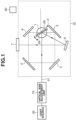
- Fig. 2 illustrates a configuration example of a part of an optical apparatus according to a first exemplary embodiment.
- the optical apparatus according to the present exemplary embodiment can control a path of emitted light (a light path).
- the optical apparatus can translate a light beam (parallel shift).
- a light beam parallel shift mechanism (a translational optical system) according to the present exemplary embodiment includes a mirror member 2 (also referred to as a reflecting member) that reflects a light beam 51 from a light source 50.
- each reflecting surface can be regarded as a flat surface and a light path is translated.
- the mirror member 2 is made of, for example, glass, and has a first reflecting surface 2a that receives the light beam 51 from the light source 50 and a second reflecting surface 2b on the opposite side.
- the first reflecting surface 2a and the second reflecting surface 2b each has a coating with a high reflectivity.
- the mirror member 2 may be formed in a prism shape, and the first reflecting surface 2a and the second reflecting surface 2b may be independent from each other. For example, they may not be on opposite sides. However, the relative positional relationship between the first reflecting surface 2a and the second reflecting surface 2b may desirably be fixed.
- the mirror member 2 is configured to be variable in its angle (a variable angular position or orientation in relation to incident light) to enable a control (change) of a path of the light that has been emitted (output) from the optical apparatus.
- Fig. 5 illustrates a configuration example of a driving part (1) that changes an angle of the reflecting member (2).
- the mirror member 2 is pivotally supported by an output shaft 1a of a (galvanometer) motor 1 (i.e., a driving part).
- a control unit 60 outputs a driving signal to the motor 1, and the motor 1 rotates the mirror member 2 via the output shaft 1a by a driving amount (i.e. an angular position or orientation change amount) corresponding to the driving signal.
- the mirror member 2 is configured to be rotatable (i.e. variable in its angle of incidence with the incident light beam).
- the mirror member 2 is inclined at about 45 degrees with respect to the light beam 51 emitted from the light source 50.
- This translational optical system has an optical system 80 that sequentially reflects light, the light having been reflected by the mirror member 2, at a plurality of reflecting surfaces to make the light incident on the mirror member 2 again by guiding the light back to the mirror member 2.
- the optical system 80 includes, for example, four mirrors 3, 4, 5, and 6 (reflecting surfaces) fixedly arranged to be axisymmetric with respect to the light beam 51. The light, having been reflected by the first reflecting surface 2a of the mirror member 2, is sequentially reflected on these mirrors 3, 4, 5, and 6 and guided to the second reflecting surface 2b of the mirror member 2.
- the optical system 80 is arranged so that the light that has been reflected on the second reflecting surface 2b and finally emitted (output) from the mirror member 2 has a travel direction that is substantially identical (or substantially parallel) to the travel direction of the light beam 51 just before it was incident on the first reflecting surface 2a.
- any optical system comprising at least one reflecting surface (mirror), or a plurality of reflecting surfaces (mirrors), may be used as long as the optical system is capable of guiding the light so that it is reflected on both the first and second reflecting surfaces 2a, 2b of the reflecting (mirror) member 2 whilst maintaining the substantially identical (or substantially parallel) travel direction between before and after the light engages the reflecting (mirror) member 2.
- the reflecting surfaces of the four mirrors 3, 4, 5, and 6 in Fig. 2 may be arranged to be at 45 degrees.
- the angle (and hence the traveling direction) of the emitted (output) light does not change even if the rotation angle (angular position or orientation) of the mirror member 2 is changed. Therefore, by using the control unit 60 to control the rotation angle (angular position or orientation) of the mirror member 2, a path of the light that has been reflected on the second reflecting surface 2b and is emitted from the mirror member 2 can be adjusted, i.e. translated or in its parallel shift adjusted.
- Fig. 3 illustrates another configuration example of a part of the optical apparatus.
- This configuration is a combination of the components illustrated in Fig. 2 and includes a first translational optical system 61 that receives the light beam 51 from the light source 50 and a second translational optical system 62 that receives the light emitted (output) from the first translational optical system 61.
- the first translational optical system 61 has an angle-variable mirror member 13 that reflects the light beam 51 emitted from the light source 50.
- the angle-variable mirror member 13 corresponds to the mirror member 2 in Fig. 1 .
- the first translational optical system 61 includes mirrors 14-1, 14-2, 14-3, and 14-4 corresponding to the mirrors 3, 4, 5 and 6 in Fig. 1 .
- incident light having been reflected by a first reflecting surface of the mirror member 13 is sequentially reflected on the mirrors 14-1, 14-2, 14-3, and 14-4, and is guided to a second reflecting surface on the side of the mirror member 13 opposite to the first reflecting surface.
- the light, having been reflected by the second reflecting surface and emitted from the mirror member 13, is incident on the mirror member 15 of the second translational optical system 62.
- the incident light having been reflected by a first reflecting surface of the mirror member 15, is sequentially reflected on the mirrors 16-1, 16-2, 16-3, and 16-4, and guided to a second reflecting surface on the side of the mirror member 15 opposite to the first reflecting surface of the mirror member 15.
- the light that has been reflected at the second reflecting surface of the mirror member 15 and finally (eventually) emitted (output) from the mirror member 15 has a travel direction that is substantially identical (substantially parallel) to the travel direction of the light beam 51 when it engaged the first reflecting surface of the mirror member 13 of the first translational optical system 61.
- a first plane comprising the light paths from the reflection by the respective mirrors of the first translational optical system 61 and a second plane comprising the light paths from the reflection by respective mirrors of the second translational optical system 62 intersect each other may be employed.
- a machining apparatus including the above-described optical apparatus (the translational optical system) and an optical system that guides (irradiates) the light, having been emitted from the optical apparatus, to an object
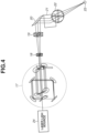
- Fig. 4 illustrates a configuration example of the machining apparatus including the optical apparatus.
- the machining apparatus according to the present exemplary embodiment includes the optical apparatus (translational optical system) 17 described with reference to Fig. 3 at the rear side (rear stage) of a laser light source 24. On the rear side thereof, the machining apparatus includes light beam expanding optical systems 18 and 19, thereby expanding the light beam so that it has the necessary translation amount and diameter.
- the above configuration allows a parallel eccentric shift of the light beam incident on the condensing optical system by the translational optical system 17, and thus allows a change (adjustment) of an angle of the laser beam that is emitted from the condensing optical system and incident on the object 23 (an incident angle).
- an incident angle As a result, it is possible to form a tapered hole on the object or the object can be cut to have an oblique cross section.
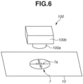
- the light incident portion 7 is provided on a cover (casing or housing) 10 of the optical apparatus and may comprise, for example, a screen (e.g., a frosted glass plate) for observing the light, the screen including an index (line 7a) used to recognize (indicate) a position of the incident light.
- a screen e.g., a frosted glass plate
- an index (line 7a) used to recognize (indicate) a position of the incident light.
- an image pickup unit 100 including, for example, a lens 100a and a television (TV) camera 100b
- TV television
- the adjustment of the light path can be performed, for example, by adjusting the two angle-variable mirrors provided between the light source 50 and the light inlet portion of the optical apparatus. More specifically, first, an angle of the angle-variable mirror closer to the light source 50 is adjusted so that the light is incident on a predetermined position in the light inlet portion. Next, an angle of an angle-variable mirror farther from the light source 50 is adjusted so that the light is incident on a predetermined position on the light incident portion 7. An incident position of the light then slightly deviates from the predetermined position in the light inlet portion. Thus, the angle of the angle-variable mirror closer to the light source 50 is adjusted again so that light is incident on the predetermined position in the light inlet portion.
- optical axis adjustment unit 70 is exemplified to have two angle-variable mirrors, the optical axis adjustment unit 70 is not limited thereto.
- the optical axis adjustment unit 70 may comprise any arrangement as long as it can change an incident position and an incident angle of light falling on the mirror member 2.
- the optical axis adjustment unit 70 can be realized by a combination of a mirror capable of changing both the incident position and the incident angle, and a fixed mirror.
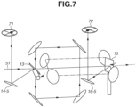
- Fig. 7 illustrates a configuration example of an optical apparatus according to a second exemplary embodiment.
- This configuration includes the first translational optical system 61 described with reference to Fig. 3 , that is, the first translational optical system 61, on which the light beam 51 emitted from the light source 50 (or the optical axis adjustment unit 70) is incident, and the second translational optical system 62 on which the light having been emitted from the first translational optical system 61 is incident.
- the mirror member 13 is set at an angle for an optical axis adjustment (i.e., an angle that is different from a predetermined angle obtained by inclining the mirror member 13 by approximately 45 degrees with respect to the light beam 51 from the light source 50).
- an optical axis adjustment i.e., an angle that is different from a predetermined angle obtained by inclining the mirror member 13 by approximately 45 degrees with respect to the light beam 51 from the light source 50.
- the light having been reflected by the mirror member 13 does not reach the mirrors 14-1, 14-2, 14-3, or 14-4, and is incident on the first light incident portion 71 via another mirror 14-5 (a reflective optical element).
- the position (deviation) of the light (beam) can be recognized (determined) by reading the position of the light incident on the first light incident portion 71 based on an index (line 7a) provided on the first light incident portion 71.
- the mirror member 13 is set at a reference angle (e.g., 45 degrees) with respect to the light beam 51 emitted from the light source 50, and the mirror member 15 is set at an angle for an optical axis adjustment (an angle that is different from a reference angle obtained by inclining the mirror member 15 by approximately 45 degrees with respect to the light beam 51 emitted from the light source 50).
- a reference angle e.g. 45 degrees
- the mirror member 15 is set at an angle for an optical axis adjustment (an angle that is different from a reference angle obtained by inclining the mirror member 15 by approximately 45 degrees with respect to the light beam 51 emitted from the light source 50).
- the light having been reflected by the mirror member 15 does not reach the mirrors 16-1, 16-2, 16-3, or 16-4, and is incident on a second light incident portion 72 via another mirror 16-5 (another reflective optical element).
- the position (deviation) of the incident light (beam) can be recognized (determined) by reading the position of the light incident on the first light incident portion 73 based on the index (line).
- the light having been reflected by the half mirror 16-6 is incident on a second light incident portion 74.
- the position (deviation) of the incident light (beam) can be recognized (determined) by reading the position of the light incident on the second light incident portion 74 based on the index (line).
- Deviation of a (passing) position of the light generated by the adjustment of the angle of the mirror, which has the angle adjusting mechanism, can be reduced (adjusted or compensated) by using an angle-variable mirror member (at least one of mirrors 13 and 15 in Fig. 3 ) for a translation of the light in the translational optical system.
- At least one of the (galvanometer) mirrors 20 and 21 in the deflection optical system is set at an angle exceeding an angle range for machining (an effective diameter of the rear optical system) so as to reduce or prevent any unintentional transmission (leakage) of the laser light.
- the setting allows the cover 10 (casing) of the optical apparatus or the machining apparatus to block the light, enabling a reduction or an elimination of the light being emitted from the machining apparatus undesirably.
- an additional component dedicated for reducing or eliminating the light such as a shutter is not needed.
- this configuration is advantageous in achieving a simplification and size-reduction of the optical apparatus or the machining apparatus.
- a method of calibrating/adjusting/controlling a position and an angle of an incident light on a light inlet of an optical scanning apparatus using the optical apparatus according to any one of first, second, or third exemplary embodiment described herein.
Landscapes
- Physics & Mathematics (AREA)
- Optics & Photonics (AREA)
- Engineering & Computer Science (AREA)
- General Physics & Mathematics (AREA)
- Plasma & Fusion (AREA)
- Mechanical Engineering (AREA)
- Laser Beam Processing (AREA)
- Mounting And Adjusting Of Optical Elements (AREA)
- Lenses (AREA)
- Mechanical Light Control Or Optical Switches (AREA)
- Mechanical Optical Scanning Systems (AREA)
Applications Claiming Priority (1)
| Application Number | Priority Date | Filing Date | Title |
|---|---|---|---|
| JP2016168612A JP6851751B2 (ja) | 2016-08-30 | 2016-08-30 | 光学装置、加工装置、および物品製造方法 |
Publications (2)
| Publication Number | Publication Date |
|---|---|
| EP3290982A1 EP3290982A1 (en) | 2018-03-07 |
| EP3290982B1 true EP3290982B1 (en) | 2025-04-16 |
Family
ID=59738183
Family Applications (1)
| Application Number | Title | Priority Date | Filing Date |
|---|---|---|---|
| EP17187820.0A Active EP3290982B1 (en) | 2016-08-30 | 2017-08-24 | Optical apparatus, machining apparatus, and article manufacturing method |
Country Status (6)
| Country | Link |
|---|---|
| US (1) | US10845589B2 (https=) |
| EP (1) | EP3290982B1 (https=) |
| JP (1) | JP6851751B2 (https=) |
| KR (1) | KR102165511B1 (https=) |
| CN (1) | CN107797270B (https=) |
| TW (1) | TWI642970B (https=) |
Families Citing this family (7)
| Publication number | Priority date | Publication date | Assignee | Title |
|---|---|---|---|---|
| JP7274989B2 (ja) * | 2019-09-05 | 2023-05-17 | 株式会社ディスコ | 光軸調整ジグおよびレーザー加工装置の光軸確認方法 |
| JP7278178B2 (ja) * | 2019-09-05 | 2023-05-19 | 株式会社ディスコ | レーザー加工装置の光軸確認方法 |
| CN110824684B (zh) * | 2019-10-28 | 2020-10-30 | 华中科技大学 | 一种高速立体三维多模态成像系统和方法 |
| US11662562B2 (en) * | 2020-02-09 | 2023-05-30 | Kla Corporation | Broadband illumination tuning |
| EP4144473A4 (en) * | 2020-04-30 | 2024-04-24 | Nikon Corporation | Processing system |
| JP7501104B2 (ja) * | 2020-05-22 | 2024-06-18 | 富士フイルムビジネスイノベーション株式会社 | 読取装置、出力装置及び画像形成装置 |
| EP4550020A1 (en) * | 2023-11-03 | 2025-05-07 | Confocal.nl B.V. | Re-scan optical system |
Citations (1)
| Publication number | Priority date | Publication date | Assignee | Title |
|---|---|---|---|---|
| US5923418A (en) * | 1995-02-21 | 1999-07-13 | Clark-Mxr, Inc. | Apparatus for controlling the position and direction of a laser beam |
Family Cites Families (22)
| Publication number | Priority date | Publication date | Assignee | Title |
|---|---|---|---|---|
| JPS6010606B2 (ja) * | 1977-05-17 | 1985-03-19 | キヤノン株式会社 | 走査効率の高い走査光学系 |
| GB2316253B (en) * | 1979-10-09 | 1998-07-01 | Rank Organisation Ltd | Combined rangefinding,thermal imaging system |
| DE3530189A1 (de) * | 1985-08-23 | 1987-03-05 | Zeiss Carl Fa | Einrichtung zur lagekorrektur eines ueber eine gelenkoptik gefuehrten laserstrahls |
| US4840483A (en) * | 1987-12-18 | 1989-06-20 | Cincinnati Milacron Inc. | Alignment tool for laser beam delivery systems and method of alignment |
| JPH0518815A (ja) * | 1991-07-10 | 1993-01-26 | Nec Corp | レーザビーム位置補正装置 |
| JP2779778B2 (ja) * | 1995-02-23 | 1998-07-23 | 株式会社篠崎製作所 | レーザ発振光オートアラインメント装置 |
| JPH10318718A (ja) * | 1997-05-14 | 1998-12-04 | Hitachi Ltd | 光学式高さ検出装置 |
| US6067127A (en) * | 1997-07-08 | 2000-05-23 | Sony Corporation | Method and apparatus for reducing the rotation rate of mirrors in a high resolution digital projection display |
| US20030197117A1 (en) * | 2002-04-22 | 2003-10-23 | Knirck Jeffrey G. | Method and apparatus for compensating a vector command to a galvanometer with light beam pointing error information |
| JP2005118815A (ja) * | 2003-10-16 | 2005-05-12 | Hitachi Via Mechanics Ltd | レーザ加工方法およびレーザ加工装置 |
| JP2006281268A (ja) * | 2005-03-31 | 2006-10-19 | Hitachi Via Mechanics Ltd | レーザ加工機 |
| TWI367800B (en) * | 2005-06-17 | 2012-07-11 | Olympus Corp | Laser beam machining method and apparatus |
| JP2007175744A (ja) * | 2005-12-28 | 2007-07-12 | Yamazaki Mazak Corp | レーザ加工機における光路軸の調整装置 |
| JP2008238184A (ja) * | 2007-03-26 | 2008-10-09 | Mitsubishi Electric Corp | レーザ加工装置 |
| JP5207827B2 (ja) * | 2008-05-22 | 2013-06-12 | キヤノン株式会社 | ガルバノ装置、加工装置、ガルバノ装置におけるミラーの倒れ角を得る方法、および、加工方法 |
| JP5540664B2 (ja) * | 2009-11-20 | 2014-07-02 | 日本電気株式会社 | 光軸調整システム、光軸調整装置、光軸調整方法、及びプログラム |
| JP5518612B2 (ja) * | 2010-07-20 | 2014-06-11 | 株式会社ディスコ | 光学装置およびこれを備えるレーザー加工装置 |
| KR20120016456A (ko) * | 2010-08-16 | 2012-02-24 | 주식회사 이오테크닉스 | 레이저 가공장치 및 레이저 가공방법 |
| JP2015141372A (ja) * | 2014-01-30 | 2015-08-03 | 株式会社ミツトヨ | 照射装置、照射方法、測定装置、及び測定方法 |
| JP6595879B2 (ja) | 2014-11-13 | 2019-10-23 | キヤノン株式会社 | 光学装置、加工装置、および、物品の製造方法 |
| EP3021153B1 (en) * | 2014-11-13 | 2018-12-12 | Canon Kabushiki Kaisha | Optical apparatus, processing apparatus, and article manufacturing method |
| JP6198805B2 (ja) | 2015-02-16 | 2017-09-20 | キヤノン株式会社 | リソグラフィ装置、リソグラフィ方法、プログラム、リソグラフィシステムおよび物品製造方法 |
-
2016
- 2016-08-30 JP JP2016168612A patent/JP6851751B2/ja active Active
-
2017
- 2017-08-14 TW TW106127414A patent/TWI642970B/zh active
- 2017-08-24 EP EP17187820.0A patent/EP3290982B1/en active Active
- 2017-08-28 US US15/688,495 patent/US10845589B2/en active Active
- 2017-08-30 CN CN201710759642.3A patent/CN107797270B/zh active Active
- 2017-08-30 KR KR1020170109815A patent/KR102165511B1/ko active Active
Patent Citations (1)
| Publication number | Priority date | Publication date | Assignee | Title |
|---|---|---|---|---|
| US5923418A (en) * | 1995-02-21 | 1999-07-13 | Clark-Mxr, Inc. | Apparatus for controlling the position and direction of a laser beam |
Also Published As
| Publication number | Publication date |
|---|---|
| EP3290982A1 (en) | 2018-03-07 |
| US10845589B2 (en) | 2020-11-24 |
| JP6851751B2 (ja) | 2021-03-31 |
| CN107797270A (zh) | 2018-03-13 |
| US20180059407A1 (en) | 2018-03-01 |
| JP2018036440A (ja) | 2018-03-08 |
| TW201807454A (zh) | 2018-03-01 |
| KR102165511B1 (ko) | 2020-10-14 |
| TWI642970B (zh) | 2018-12-01 |
| KR20180025262A (ko) | 2018-03-08 |
| CN107797270B (zh) | 2021-04-30 |
Similar Documents
| Publication | Publication Date | Title |
|---|---|---|
| EP3290982B1 (en) | Optical apparatus, machining apparatus, and article manufacturing method | |
| US6791057B1 (en) | Method and device for machining workpieces using high-energy radiation | |
| CN1644296B (zh) | 激光加工设备 | |
| EP2561586B1 (en) | Laser beam analysis apparatus | |
| TWI398717B (zh) | 自動對焦控制單元、電子裝置及自動對焦控制方法 | |
| CN103476537A (zh) | 用于使激光射束聚焦的装置和用于监控激光加工的方法 | |
| CN101573204A (zh) | 激光束加工装置以及聚焦位置的调节方法 | |
| CN212470240U (zh) | 一种光束指向稳定性监测与反馈装置 | |
| US11878367B2 (en) | Optical device and article manufacturing method | |
| US20230330773A1 (en) | Laser processing device | |
| US6836329B1 (en) | Real time IR optical sensor | |
| JP2008145160A (ja) | 光学式変位センサ及びその調整方法 | |
| CN110382159B (zh) | 用于识别工件接合位置的方法和激光加工头 | |
| JP2007524073A (ja) | 照準装置及び非接触で又は接触させて使用可能な測定装置 | |
| TWI604220B (zh) | 光學裝置、處理裝置及物品製造方法 | |
| JP7793339B2 (ja) | 検出装置、補正装置、加工装置、および、物品の製造方法 | |
| JP2002509032A (ja) | ワークピース照明装置 | |
| US11906435B2 (en) | System including auto-alignment | |
| KR20170000936A (ko) | 분광 측정 장치의 측정 헤드 정렬 장치 | |
| US20090219506A1 (en) | Heterodyne laser doppler probe and measurement system using the same | |
| KR920006587B1 (ko) | 광축 평행도 측정장치 | |
| JP2023161992A (ja) | 加工装置及び物品の製造方法 | |
| WO2007063343A1 (en) | Laser processing tool | |
| HK1077250B (en) | Laser machining apparatus | |
| JP2005195390A (ja) | 光フィルタの特性検査用位置調整治具およびその調整方法 |
Legal Events
| Date | Code | Title | Description |
|---|---|---|---|
| PUAI | Public reference made under article 153(3) epc to a published international application that has entered the european phase |
Free format text: ORIGINAL CODE: 0009012 |
|
| STAA | Information on the status of an ep patent application or granted ep patent |
Free format text: STATUS: THE APPLICATION HAS BEEN PUBLISHED |
|
| AK | Designated contracting states |
Kind code of ref document: A1 Designated state(s): AL AT BE BG CH CY CZ DE DK EE ES FI FR GB GR HR HU IE IS IT LI LT LU LV MC MK MT NL NO PL PT RO RS SE SI SK SM TR |
|
| AX | Request for extension of the european patent |
Extension state: BA ME |
|
| STAA | Information on the status of an ep patent application or granted ep patent |
Free format text: STATUS: REQUEST FOR EXAMINATION WAS MADE |
|
| 17P | Request for examination filed |
Effective date: 20180907 |
|
| RBV | Designated contracting states (corrected) |
Designated state(s): AL AT BE BG CH CY CZ DE DK EE ES FI FR GB GR HR HU IE IS IT LI LT LU LV MC MK MT NL NO PL PT RO RS SE SI SK SM TR |
|
| STAA | Information on the status of an ep patent application or granted ep patent |
Free format text: STATUS: EXAMINATION IS IN PROGRESS |
|
| 17Q | First examination report despatched |
Effective date: 20220217 |
|
| GRAP | Despatch of communication of intention to grant a patent |
Free format text: ORIGINAL CODE: EPIDOSNIGR1 |
|
| STAA | Information on the status of an ep patent application or granted ep patent |
Free format text: STATUS: GRANT OF PATENT IS INTENDED |
|
| RIC1 | Information provided on ipc code assigned before grant |
Ipc: B23K 26/082 20140101ALI20241009BHEP Ipc: B23K 26/06 20140101ALI20241009BHEP Ipc: B23K 26/38 20140101ALI20241009BHEP Ipc: B23K 26/382 20140101ALI20241009BHEP Ipc: G02B 26/10 20060101ALI20241009BHEP Ipc: G02B 26/08 20060101ALI20241009BHEP Ipc: G02B 7/182 20060101ALI20241009BHEP Ipc: B23K 26/04 20140101ALI20241009BHEP Ipc: G02B 19/00 20060101AFI20241009BHEP |
|
| INTG | Intention to grant announced |
Effective date: 20241107 |
|
| GRAS | Grant fee paid |
Free format text: ORIGINAL CODE: EPIDOSNIGR3 |
|
| GRAA | (expected) grant |
Free format text: ORIGINAL CODE: 0009210 |
|
| STAA | Information on the status of an ep patent application or granted ep patent |
Free format text: STATUS: THE PATENT HAS BEEN GRANTED |
|
| AK | Designated contracting states |
Kind code of ref document: B1 Designated state(s): AL AT BE BG CH CY CZ DE DK EE ES FI FR GB GR HR HU IE IS IT LI LT LU LV MC MK MT NL NO PL PT RO RS SE SI SK SM TR |
|
| REG | Reference to a national code |
Ref country code: GB Ref legal event code: FG4D |
|
| REG | Reference to a national code |
Ref country code: CH Ref legal event code: EP |
|
| REG | Reference to a national code |
Ref country code: IE Ref legal event code: FG4D |
|
| REG | Reference to a national code |
Ref country code: DE Ref legal event code: R096 Ref document number: 602017088917 Country of ref document: DE |
|
| REG | Reference to a national code |
Ref country code: NL Ref legal event code: MP Effective date: 20250416 |
|
| PG25 | Lapsed in a contracting state [announced via postgrant information from national office to epo] |
Ref country code: NL Free format text: LAPSE BECAUSE OF FAILURE TO SUBMIT A TRANSLATION OF THE DESCRIPTION OR TO PAY THE FEE WITHIN THE PRESCRIBED TIME-LIMIT Effective date: 20250416 |
|
| REG | Reference to a national code |
Ref country code: AT Ref legal event code: MK05 Ref document number: 1786110 Country of ref document: AT Kind code of ref document: T Effective date: 20250416 |
|
| PG25 | Lapsed in a contracting state [announced via postgrant information from national office to epo] |
Ref country code: PT Free format text: LAPSE BECAUSE OF FAILURE TO SUBMIT A TRANSLATION OF THE DESCRIPTION OR TO PAY THE FEE WITHIN THE PRESCRIBED TIME-LIMIT Effective date: 20250818 Ref country code: FI Free format text: LAPSE BECAUSE OF FAILURE TO SUBMIT A TRANSLATION OF THE DESCRIPTION OR TO PAY THE FEE WITHIN THE PRESCRIBED TIME-LIMIT Effective date: 20250416 Ref country code: ES Free format text: LAPSE BECAUSE OF FAILURE TO SUBMIT A TRANSLATION OF THE DESCRIPTION OR TO PAY THE FEE WITHIN THE PRESCRIBED TIME-LIMIT Effective date: 20250416 |
|
| PGFP | Annual fee paid to national office [announced via postgrant information from national office to epo] |
Ref country code: DE Payment date: 20250724 Year of fee payment: 9 |
|
| REG | Reference to a national code |
Ref country code: LT Ref legal event code: MG9D |
|
| PG25 | Lapsed in a contracting state [announced via postgrant information from national office to epo] |
Ref country code: GR Free format text: LAPSE BECAUSE OF FAILURE TO SUBMIT A TRANSLATION OF THE DESCRIPTION OR TO PAY THE FEE WITHIN THE PRESCRIBED TIME-LIMIT Effective date: 20250717 Ref country code: NO Free format text: LAPSE BECAUSE OF FAILURE TO SUBMIT A TRANSLATION OF THE DESCRIPTION OR TO PAY THE FEE WITHIN THE PRESCRIBED TIME-LIMIT Effective date: 20250716 |
|
| PG25 | Lapsed in a contracting state [announced via postgrant information from national office to epo] |
Ref country code: PL Free format text: LAPSE BECAUSE OF FAILURE TO SUBMIT A TRANSLATION OF THE DESCRIPTION OR TO PAY THE FEE WITHIN THE PRESCRIBED TIME-LIMIT Effective date: 20250416 |
|
| PGFP | Annual fee paid to national office [announced via postgrant information from national office to epo] |
Ref country code: IT Payment date: 20250723 Year of fee payment: 9 |
|
| PG25 | Lapsed in a contracting state [announced via postgrant information from national office to epo] |
Ref country code: BG Free format text: LAPSE BECAUSE OF FAILURE TO SUBMIT A TRANSLATION OF THE DESCRIPTION OR TO PAY THE FEE WITHIN THE PRESCRIBED TIME-LIMIT Effective date: 20250416 |
|
| PGFP | Annual fee paid to national office [announced via postgrant information from national office to epo] |
Ref country code: GB Payment date: 20250725 Year of fee payment: 9 |
|
| PG25 | Lapsed in a contracting state [announced via postgrant information from national office to epo] |
Ref country code: HR Free format text: LAPSE BECAUSE OF FAILURE TO SUBMIT A TRANSLATION OF THE DESCRIPTION OR TO PAY THE FEE WITHIN THE PRESCRIBED TIME-LIMIT Effective date: 20250416 |
|
| PG25 | Lapsed in a contracting state [announced via postgrant information from national office to epo] |
Ref country code: AT Free format text: LAPSE BECAUSE OF FAILURE TO SUBMIT A TRANSLATION OF THE DESCRIPTION OR TO PAY THE FEE WITHIN THE PRESCRIBED TIME-LIMIT Effective date: 20250416 |
|
| PG25 | Lapsed in a contracting state [announced via postgrant information from national office to epo] |
Ref country code: RS Free format text: LAPSE BECAUSE OF FAILURE TO SUBMIT A TRANSLATION OF THE DESCRIPTION OR TO PAY THE FEE WITHIN THE PRESCRIBED TIME-LIMIT Effective date: 20250716 |
|
| PG25 | Lapsed in a contracting state [announced via postgrant information from national office to epo] |
Ref country code: IS Free format text: LAPSE BECAUSE OF FAILURE TO SUBMIT A TRANSLATION OF THE DESCRIPTION OR TO PAY THE FEE WITHIN THE PRESCRIBED TIME-LIMIT Effective date: 20250816 |
|
| PG25 | Lapsed in a contracting state [announced via postgrant information from national office to epo] |
Ref country code: LV Free format text: LAPSE BECAUSE OF FAILURE TO SUBMIT A TRANSLATION OF THE DESCRIPTION OR TO PAY THE FEE WITHIN THE PRESCRIBED TIME-LIMIT Effective date: 20250416 |
|
| PG25 | Lapsed in a contracting state [announced via postgrant information from national office to epo] |
Ref country code: SM Free format text: LAPSE BECAUSE OF FAILURE TO SUBMIT A TRANSLATION OF THE DESCRIPTION OR TO PAY THE FEE WITHIN THE PRESCRIBED TIME-LIMIT Effective date: 20250416 Ref country code: DK Free format text: LAPSE BECAUSE OF FAILURE TO SUBMIT A TRANSLATION OF THE DESCRIPTION OR TO PAY THE FEE WITHIN THE PRESCRIBED TIME-LIMIT Effective date: 20250416 |
|
| REG | Reference to a national code |
Ref country code: DE Ref legal event code: R097 Ref document number: 602017088917 Country of ref document: DE |
|
| PG25 | Lapsed in a contracting state [announced via postgrant information from national office to epo] |
Ref country code: CZ Free format text: LAPSE BECAUSE OF FAILURE TO SUBMIT A TRANSLATION OF THE DESCRIPTION OR TO PAY THE FEE WITHIN THE PRESCRIBED TIME-LIMIT Effective date: 20250416 |
|
| PG25 | Lapsed in a contracting state [announced via postgrant information from national office to epo] |
Ref country code: EE Free format text: LAPSE BECAUSE OF FAILURE TO SUBMIT A TRANSLATION OF THE DESCRIPTION OR TO PAY THE FEE WITHIN THE PRESCRIBED TIME-LIMIT Effective date: 20250416 |
|
| PG25 | Lapsed in a contracting state [announced via postgrant information from national office to epo] |
Ref country code: SK Free format text: LAPSE BECAUSE OF FAILURE TO SUBMIT A TRANSLATION OF THE DESCRIPTION OR TO PAY THE FEE WITHIN THE PRESCRIBED TIME-LIMIT Effective date: 20250416 Ref country code: RO Free format text: LAPSE BECAUSE OF FAILURE TO SUBMIT A TRANSLATION OF THE DESCRIPTION OR TO PAY THE FEE WITHIN THE PRESCRIBED TIME-LIMIT Effective date: 20250416 |
|
| PLBE | No opposition filed within time limit |
Free format text: ORIGINAL CODE: 0009261 |
|
| STAA | Information on the status of an ep patent application or granted ep patent |
Free format text: STATUS: NO OPPOSITION FILED WITHIN TIME LIMIT |
|
| REG | Reference to a national code |
Ref country code: CH Ref legal event code: L10 Free format text: ST27 STATUS EVENT CODE: U-0-0-L10-L00 (AS PROVIDED BY THE NATIONAL OFFICE) Effective date: 20260225 |
|
| REG | Reference to a national code |
Ref country code: CH Ref legal event code: H13 Free format text: ST27 STATUS EVENT CODE: U-0-0-H10-H13 (AS PROVIDED BY THE NATIONAL OFFICE) Effective date: 20260324 |
|
| 26N | No opposition filed |
Effective date: 20260119 |
|
| PG25 | Lapsed in a contracting state [announced via postgrant information from national office to epo] |
Ref country code: MC Free format text: LAPSE BECAUSE OF FAILURE TO SUBMIT A TRANSLATION OF THE DESCRIPTION OR TO PAY THE FEE WITHIN THE PRESCRIBED TIME-LIMIT Effective date: 20250416 |
|
| PG25 | Lapsed in a contracting state [announced via postgrant information from national office to epo] |
Ref country code: LU Free format text: LAPSE BECAUSE OF NON-PAYMENT OF DUE FEES Effective date: 20250824 |
|
| PG25 | Lapsed in a contracting state [announced via postgrant information from national office to epo] |
Ref country code: CH Free format text: LAPSE BECAUSE OF NON-PAYMENT OF DUE FEES Effective date: 20250831 |