EP3290813A1 - Dispositif d'évacuation de vapeurs et appareil combiné pourvu de dispositif d'évacuation de vapeurs - Google Patents
Dispositif d'évacuation de vapeurs et appareil combiné pourvu de dispositif d'évacuation de vapeurs Download PDFInfo
- Publication number
- EP3290813A1 EP3290813A1 EP17186265.9A EP17186265A EP3290813A1 EP 3290813 A1 EP3290813 A1 EP 3290813A1 EP 17186265 A EP17186265 A EP 17186265A EP 3290813 A1 EP3290813 A1 EP 3290813A1
- Authority
- EP
- European Patent Office
- Prior art keywords
- extractor
- container
- housing
- collecting container
- guide
- Prior art date
- Legal status (The legal status is an assumption and is not a legal conclusion. Google has not performed a legal analysis and makes no representation as to the accuracy of the status listed.)
- Granted
Links
- 239000003517 fume Substances 0.000 title claims abstract description 21
- 238000000605 extraction Methods 0.000 title claims abstract description 19
- 239000007788 liquid Substances 0.000 claims abstract description 73
- 238000004140 cleaning Methods 0.000 description 8
- 238000010411 cooking Methods 0.000 description 4
- 239000012530 fluid Substances 0.000 description 4
- 238000011109 contamination Methods 0.000 description 3
- 238000009833 condensation Methods 0.000 description 2
- 230000005494 condensation Effects 0.000 description 2
- 239000000470 constituent Substances 0.000 description 2
- 238000010276 construction Methods 0.000 description 2
- 239000012535 impurity Substances 0.000 description 2
- 238000007789 sealing Methods 0.000 description 2
- XLYOFNOQVPJJNP-UHFFFAOYSA-N water Substances O XLYOFNOQVPJJNP-UHFFFAOYSA-N 0.000 description 2
- 238000010521 absorption reaction Methods 0.000 description 1
- 230000004308 accommodation Effects 0.000 description 1
- 239000004519 grease Substances 0.000 description 1
- 238000010438 heat treatment Methods 0.000 description 1
- 230000006698 induction Effects 0.000 description 1
- 238000012423 maintenance Methods 0.000 description 1
- 230000013011 mating Effects 0.000 description 1
- 230000001681 protective effect Effects 0.000 description 1
- 125000006850 spacer group Chemical group 0.000 description 1
- 238000009423 ventilation Methods 0.000 description 1
Images

Classifications
-
- F—MECHANICAL ENGINEERING; LIGHTING; HEATING; WEAPONS; BLASTING
- F24—HEATING; RANGES; VENTILATING
- F24C—DOMESTIC STOVES OR RANGES ; DETAILS OF DOMESTIC STOVES OR RANGES, OF GENERAL APPLICATION
- F24C15/00—Details
- F24C15/20—Removing cooking fumes
- F24C15/2042—Devices for removing cooking fumes structurally associated with a cooking range e.g. downdraft
Definitions
- the present invention relates to a fume extraction device and a combination device with extractor device.
- Extractor devices For cleaning air, in particular fumes and vapors, which occur during cooking, it is known to use extractor devices, is sucked through the air through a filter and cleaned on the filter.
- Vapor extraction devices can be designed as an extractor hood, which sucks the air upwards.
- extractor devices are also referred to as a tray ventilator.
- This type of extractor device can be arranged in or next to the hob. The inflow opening, via which air enters the extractor device, lies in the horizontal plane.
- Object of the present invention is therefore to provide a solution in which the operation and safety of the extractor device are ensured in a simple way and with a simple construction of the extractor device.
- the invention is based on the finding that this object can be achieved by providing a collecting container and a liquid guide leading away from the collecting container to the extractor device, which leads to an additional container.
- the object is therefore achieved by a fume extraction device having a fan, a fume hood housing and a filter unit.
- the extractor device is characterized in that the extractor device comprises a collection container for liquids with at least one overflow opening and an additional container for liquids and at least partially a liquid line between the collecting container and the additional container.
- the extractor device is a device by means of which contaminated air, in particular fumes and vapors produced during cooking, can be sucked in.
- a filter unit is provided in the extractor device, which preferably has at least one filter element.
- the extractor device also has a fan and a fume hood housing. As a fan consisting of a fan motor and fan component is called. The fan is preferably a radial fan.
- extractor housing As extractor housing according to the invention a component is referred to, in which at least the fan of the extractor device is added. Preferably, all necessary for the operation of the extractor device elements are provided in or on the extractor housing.
- the extractor housing preferably has a receiving space for the fan.
- the extractor housing preferably has an inflow opening, via which air can enter into the extractor device and in which the filter unit is preferably arranged.
- at least one receiving space for electronic components which serve to operate the fan can be provided in the extractor housing.
- the extractor device is characterized in that the extractor device comprises a collection container for liquids and an additional container for liquids.
- the collection container for liquids preferably represents a container in which at least directly from a filter element leaking liquids can be collected.
- the liquids in particular constitute condensate or fat.
- other liquids for example condensate which has formed on further parts of the filter unit, or liquids which run into the filter unit or drip into it can also be collected in the collecting container.
- the collecting container has at least one overflow opening.
- an overflow opening here is an opening which is offset up to the bottom of the collecting container but is spaced down to the upper edge of the collecting container.
- a container is referred to, which preferably has a greater absorption capacity than the collecting container.
- the additional container is a container that is separate from the collecting container. Preferably, liquid can reach the additional container only via the collecting container.
- a fluid conduit is a device or a part of a device which is suitable for conducting fluid.
- the liquid line can consist of several components, wherein one or more constituents can represent hollow bodies and one or more constituents can represent channels or open channels.
- a collecting container and an additional container are provided in the extractor device according to the invention, a larger amount of liquids can be received, as in extractor devices, in which only a collecting container is provided. This makes it possible, for example, when overcooking food, catch all the liquid entering the extractor device in the containers and so prevent contamination or damage to other components of the extractor device.
- a liquid line is provided which forms at least one region between the collecting container and the additional container, on the one hand an uncontrolled flow of liquids between the two containers can be prevented.
- the position of the additional container with respect to the collecting container can be freely selected.
- the additional tank need not be arranged so that liquid can drip or overflow directly from the sump into the auxiliary tank. A vertically superimposed arrangement of the container is thus not required. As a result, the height of the extractor device is reduced.
- the liquid line is at least partially formed on the extractor housing.
- the liquid line can be partially formed by a guide geometry which is located on an outer side of the extractor housing and in particular on the upper side of the extractor housing.
- To the Extractor hood is provided an air inlet opening through which the air is sucked into a lying in the extractor housing receiving space for a fan.
- the extractor housing and in particular the air inlet opening are therefore preferably in or in the vicinity of the inlet opening is sucked through the air in the extractor device and in which preferably the filter unit is provided.
- the part of the liquid line, which is at least partially formed on the extractor housing liquid in the immediate vicinity of the inlet opening of the extractor device can be received and directed.
- the number of parts will be reduced by forming at least a portion of the liquid line on the extractor housing.
- the collecting container is part of a filter unit.
- a filter unit a unit of the extractor device is referred to, which comprises at least one filter element.
- at least one filter element is at least partially received in the collecting container.
- the filter element or the filter elements are preferably removable from the collecting container, that is releasably connected to the collecting container or used in this.
- a filter element is referred to, in which at least a part of the filter element is located in the collecting container.
- the filter element is inclined to the bottom of the sump at an angle in the sump. In this embodiment, at least the lower edge of the filter element is received in the sump and may, for example, rest on the bottom of the sump or on a protrusion offset up to the bottom.
- the filter unit is preferably arranged in the region of the inflow opening of the extractor device in order to filter out impurities from the air there.
- the filter unit and thus also the collection container are accessible to the user. This is especially important for cleaning and maintenance purposes.
- the auxiliary container is releasably attached to the extractor housing.
- the releasable attachment may, for example, a screw, be a plug connection or a locking connection.
- the advantage of the detachable connection is that the additional container can be removed from the extractor device. When removed, the additional tank can be emptied. Such emptying is particularly important in the additional container, as this preferably has a larger capacity than the sump and a cleaning of the additional container in the state attached to the extractor device state may not be possible.
- a fastening device for the additional container is arranged on the extractor housing.
- the fastening device may be attached to the extractor housing or be made in one piece with this, that is to be molded.
- the fastening device is arranged on the extractor housing and preferably rigidly thereto, the position of the additional container with respect to the extractor housing can be defined and a reliable guiding of liquids to the additional container can be ensured.
- the attachment device for the additional container is provided on the extractor housing, the construction of the extractor device further simplified.
- the fastening device is, for example, a thread.
- a thread about this thread a provided with a corresponding mating thread additional container can be screwed.
- the advantage of having the connection by means of a thread is that it can also carry a great weight on the one hand. On the other hand, this connection is tight at least with regard to liquids. An uncontrolled leakage of liquids at the junction can therefore be prevented.
- the invention relates to a combination device comprising a hob and a fume extraction device.
- the combination device is characterized in that the extractor device is an extractor device according to the invention.
- the combination device comprises a hob and a fume extraction device. These two elements can have a common power connection and, for example, be controlled by a common control unit.
- the extractor device is at least partially below the hob.
- the extractor device can therefore also be referred to as a cooktop extractor or tray deduction or tray ventilator.
- Directional information such as above or below relate - unless otherwise stated - to an embodiment of the extractor device, in which it is at least partially arranged in the assembled state below a hob and in which the air inlet opening of the extractor housing is on top.
- the advantages of the present invention in particular the small space required for the extractor device, can be used particularly well.
- the probability of the entry of liquids into the extractor device is particularly high.
- the extractor housing has a receiving space for a fan of the extractor device and in the top of the receiving space an air inlet opening is introduced.
- the fan located in the receiving space preferably represents a radial fan whose fan wheel axis is perpendicular to the air inlet opening.
- a guide geometry is formed as part of the liquid line at the top of the extractor housing.
- the guide geometry comprises an increase at the edge of the air inlet opening and an outwardly offset to the increase guide wall.
- an improved air flow can be ensured in the air inlet opening.
- the increase can also be used to protect against uncontrolled entry of liquids located on top of the extractor housing, in which the air inlet opening is introduced, serve.
- the increase is part of the fluid line, in particular part of the guide geometry and forms an open channel with the guide wall.
- the guide wall extends upwardly from the top of the extractor housing.
- the guide wall in addition to the management of liquids, for example, as a spacer to another component, in particular the cover plate of the hob, serve.
- the guide wall extends further beyond the top of the extractor housing than the increase provided around the air inlet opening.
- part of the filter unit, in particular the collecting container can be received in the guide wall.
- the shape of the guide wall is preferably adapted to the shape of the opening in the hob and the filter unit and may for example represent a rectangular circumferential wall.
- the liquid line comprises a guide channel.
- a guide channel in particular a channel is referred to with a continuous cross section, for example a rectangular cross section.
- the guide channel can therefore also be referred to as a closed channel.
- the underside of the guide channel can be formed at least over part of its length through the top of the extractor housing. On top of a tunnel is then applied or molded, which covers the channel upwards. By using a guide channel, leakage of liquid upwards can be prevented.
- the guide channel is preferably outside the guide wall and in the guide wall, an outlet opening is provided, through which the guide channel with the within the bounded by the guide wall space geometry connected is.
- the guide channel extends beyond the outer edge of the receiving space of the extractor housing.
- the edge in the radial direction that is to say in the direction of the radius of the fan wheel to be provided in the receiving space, is understood as the outer edge of the receiving space.
- the extractor housing is preferably arranged so that the axis of the fan wheel is perpendicular to the air inlet opening and the air inlet opening is located in the vicinity of the inflow opening, in the embodiment in which the guide channel over the outer edge extends the receiving space, the additional container at the end of the guide channel and thus be arranged next to the receiving space.
- a fastening device for the additional container lies at the outer end of the guide channel, a fastening device for the additional container.
- the attachment device may be, for example, an upwardly threaded closure with an inlet for liquids from the guide channel.
- the attachment device for the auxiliary container is adjacent to the receiving space of the extractor housing for the fan.
- the receiving space of the fan of the extractor device is arranged.
- an air inlet opening is introduced.
- the sump is releasably held in the hob.
- a recess is preferably introduced in a cover plate of the hob.
- the sump can be used.
- the sump is removable upwards.
- the filter element or the filter elements of the filter unit can be at least partially accommodated in the collecting container.
- the collection container may also be referred to as part of the filter unit.
- the collecting container is detachable, the collecting container can be removed for cleaning purposes.
- the collecting container is particularly removable from the top of the hob, the collecting container can be removed from the hob by lifting, without that leakage of liquid in the container is to be feared.
- the additional container is removable from below from the extractor device and in particular from the extractor housing.
- This embodiment is advantageous because the additional container due to its preferably larger Capacity can have a large weight. Lowering of such an additional container when removing the additional container is therefore easier for the user than lifting.
- the upper side of the extractor housing at least in the region of the liquid line, has an inclination out of the horizontal.
- the combination device can also have a cooking hob, in which a recess is preferably made, having a fume extraction device which has a fume hood housing.
- a guide geometry may be formed as part of the fluid conduit which merges into a guide channel extending over an outer edge of the extractor housing.
- the collecting container may be placed on the guide geometry and the overflow opening of the collecting container is aligned with a part of the guide geometry.
- the overflow opening is aligned with the guide geometry, the liquid that emerges from the collection runs in the guide geometry and drips, for example, from above into an open channel of the guide geometry.
- a combination device which may also be referred to as a device, which consists of a cooktop with an integrated extractor device, which may also be referred to as a ventilation unit.
- a system is installed that collects condensate or other liquids.
- condensate is collected, which is reflected for example on the filter elements of the extractor device.
- steam / fat vapor is generated, which in most cases leads to condensation in the region of the inflow opening, which can also be referred to as suction zone, of the extractor device.
- overflow liquid is collected if, for example a larger amount of water was spilled on the hob or in the suction zone.
- condensate which occurs during normal operation of the combination device can be collected in the collecting container, which constitutes a first container.
- This first container has a limited capacity.
- the sump offers an overflow function. If a larger amount of liquid is to be taken up, it will run into the additional tank, which offers a larger capacity.
- the sump can be removed from above by the customer for emptying and cleaning and is dishwasher safe.
- the additional container has a larger capacity and is removable from below for emptying and cleaning and is also dishwasher safe.
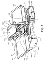
- FIG. 1 is a schematic, perspective sectional view of an embodiment of the extractor device 11 in one embodiment of a combination device 1 is shown.
- the combination device 1 consists of a hob 10 and a fume extractor 11.
- the hob 10 includes a cover plate 102 and a arranged below the cover plate 102 cooktop housing 101.
- heating modules (not shown), such as induction modules, recorded.
- the hob 10 in particular in the cover plate 102 has a recess 103 is introduced.
- the extractor device 11 has a fan (not shown), a fume hood 110 and a filter unit 14.
- the filter unit 14 has two filter elements 140 in the illustrated embodiment.
- the filter elements 140 are held in a filter holder 141.
- the filter holder has a cover 1410, which covers the surface of the recess 103 in the cover plate 102 and are introduced into the two suction openings 1411.
- two filter elements 140 are used in the filter holder 141.
- the filter elements 140 are inclined in the illustrated embodiment at an angle to the horizontal and the vertical.
- the filter holder 141 with the filter elements 140 is inserted into a collecting container 142.
- the collecting container 142 represents an upwardly open trough.
- a passage opening 143 is introduced in the bottom of the collecting container 142.
- the bottom of the collecting container is formed by grooves 1420.
- two grooves 1420 are provided, which extend over the length of the collecting container 142 and are arranged adjacent to the passage opening 143, that is, lie to the right and left of the passage opening 143.
- the passage opening 143 is arranged elevated relative to the grooves 1420 in the collecting container 142.
- overflow openings 1421 are introduced.
- the overflow openings 1421 are at a height which is less than the middle part of the bottom of the collecting container 142 in which the passage opening 143 is located.
- the collecting container 142 has at the upper end a fold 1422 which extends to the outside. By this fold 1422 of the collecting container 142 is held in the recess 103 of the cover plate 102 of the hob 10.
- the extractor housing 110 has a receiving space 111, in which the fan (not shown) of the extractor device 11 is received.
- a receiving space 111 In the top 113 of the extractor housing 110 and in particular of the receiving space 111, which is also referred to as a base, an air inlet opening 112 is introduced.
- the side wall 114 is located at the edge of the upper side.
- the air inlet opening 112 is aligned with the passage opening 143 of the collection container 142 under the filter unit 14.
- a protective grid is provided in the air inlet opening 112. At the edge of the air inlet opening 112, this is surrounded by an annular elevation 132.
- a guide wall 133 on the upper side 113 of the receiving space 111 is provided, which extends upwards.
- the guide wall 133 projects through a distance between two cooktop housings 101 to the underside of the cover plate 102 of the cooktop 10.
- the inflow opening 115 of the extractor housing 110 is defined by the guide wall.
- a guide geometry 134 is formed, which is open at the top. Only through the underside of the grooves 1420 of the collecting container 142, this guide geometry 134 is covered upwards.
- an outlet port 135 is provided at one location.
- a guide channel 130 Adjoining this outlet opening 135 is a guide channel 130, which is preferably an upwardly closed channel which is formed on the upper side 113 of the receiving space 111.
- the guide channel 130 extends laterally beyond the edge of the upper side 113 of the receiving space 111.
- a lid 131 is formed at the end of the guide channel 130, which protrudes laterally beyond the top 113.
- the cover 131 is a component which is closed at the top and on which there is preferably a fastening device 136 for fastening an additional container 12.
- the fastening device 136 represents, for example, an internal thread on the cover 131. From below, an additional container 12 is detachably fastened to the cover 131, in particular screwed over its container neck 120.
- the auxiliary container 12 has a height which corresponds to that of the receiving space 111 of the extractor hood 110.
- the containers 142, 12 and the guide line 13 can be seen more accurately.
- the upper side 113 of the fan accommodating space 111 is inclined to one side.
- the top 113 may be inclined over its entire surface. But it is also possible that only in the region of the outlet opening 135 in the guide wall 133, the surface 113 is inclined.
- the path of liquids in the extractor device 11 is in the FIGS. 1 and 2 indicated by arrows F.
- Air is extracted by the fan (not shown) from the environment, in particular from the hob 10. This air passes through the filter elements 140 of the filter unit 14 and is there freed of impurities, especially water / grease.
- the liquids which are deposited on the filter elements 140 for example by condensation, run downwards on the filter elements 140 and thus reach the bottom of the collecting container 142, in particular into those formed there
- liquid can pass directly from the suction openings 1411 of the filter unit 14 in the cover 1410 to the grooves 1420 of the collecting container 142. This case occurs, for example, when overcooking or spilling food.
- the liquid enters the guide geometry 134, which is formed on the upper side 113 of the receiving space 111 of the extractor housing 110.
- the liquid is passed between the elevation 132, which is provided at the edge of the air inlet opening 112 and the guide wall 133 and thus reaches the outlet opening 135 in the guide wall 133.
- the outlet opening 135 the liquid passes into the guide channel 130 and from there into the auxiliary container 12.
- the flow of the liquid to the additional container 12 is favored by the inclination of the upper side 113 in the region of the guide geometry 134 and the guide channel 130.
- the collecting container 142 with the filter holder 141 can be lifted out of the recess 103 in the cover plate 102 of the hob 10.
- the filter holder 141 is preferably detachable from the collecting container 142
- the filter holder 141 with the filter elements 140 can also be removed in a first step, and then the collecting container 142 can be taken out.
- the guide geometry 134 on the upper side 113 of the receiving space 111 of the extractor housing 11 is accessible through the recess 103 in the cover plate 102 of the hob 10. The user can clean it, especially wipe it. Due to the inclination, the amount of liquid remaining in this guide geometry 143 is small, so that wiping is sufficient.
- the auxiliary container 12 can be removed from below from the fastening device 136 in the lid 131 of the liquid line 13. In a screw cap, the additional container 12 is unscrewed from the internal thread on the lid 131. In the removed state, the additional container 12 can be emptied and cleaned.
- Both the collecting container 142 and the additional container 12 may for example consist of plastic and be cleaned in the dishwasher.
- the present invention has a number of advantages. First, contamination and consequent damage to the extractor device, in particular the fan of the extractor device are reliably prevented. Furthermore, the extractor device has a simple structure and can be easily maintained and cleaned. Finally, in the embodiment in which the auxiliary container is arranged adjacent to a receiving space in the extractor housing for the fan, the overall height is not increased by the inventive liquid supply system.
Landscapes
- Engineering & Computer Science (AREA)
- Chemical & Material Sciences (AREA)
- Combustion & Propulsion (AREA)
- Mechanical Engineering (AREA)
- General Engineering & Computer Science (AREA)
- Apparatus For Making Beverages (AREA)
Applications Claiming Priority (1)
| Application Number | Priority Date | Filing Date | Title |
|---|---|---|---|
| EP16290159 | 2016-08-26 |
Publications (2)
| Publication Number | Publication Date |
|---|---|
| EP3290813A1 true EP3290813A1 (fr) | 2018-03-07 |
| EP3290813B1 EP3290813B1 (fr) | 2019-11-20 |
Family
ID=56893907
Family Applications (1)
| Application Number | Title | Priority Date | Filing Date |
|---|---|---|---|
| EP17186265.9A Active EP3290813B1 (fr) | 2016-08-26 | 2017-08-15 | Dispositif d'évacuation de vapeurs et appareil combiné pourvu de dispositif d'évacuation de vapeurs |
Country Status (1)
| Country | Link |
|---|---|
| EP (1) | EP3290813B1 (fr) |
Cited By (4)
| Publication number | Priority date | Publication date | Assignee | Title |
|---|---|---|---|---|
| CN110578943A (zh) * | 2018-06-08 | 2019-12-17 | Bsh家用电器有限公司 | 烟雾排出装置和带有烟雾排出装置和灶台的组合设备 |
| EP3951270A1 (fr) * | 2020-08-05 | 2022-02-09 | Electrolux Appliances Aktiebolag | Appareil combiné |
| EP4043799A1 (fr) | 2021-02-16 | 2022-08-17 | Electrolux Appliances Aktiebolag | Hotte aspirante pour une plaque de cuisson et procédé de fonctionnement d'une hotte aspirante |
| EP4063747A1 (fr) * | 2021-03-26 | 2022-09-28 | Emc Fime S.R.L. | Unité d'aspiration pour plaques de cuisson |
Citations (6)
| Publication number | Priority date | Publication date | Assignee | Title |
|---|---|---|---|---|
| DE2641708A1 (de) * | 1976-09-16 | 1978-03-30 | Paul Gutermuth | Feuchtraumdecke |
| US5537988A (en) * | 1995-08-21 | 1996-07-23 | Sung-Lin Huang | Grease guiding tray for a kitchen ventilator |
| US5975075A (en) * | 1997-10-07 | 1999-11-02 | Haiki Co., Ltd. | Exhauster for cooking |
| US6041774A (en) * | 1998-11-13 | 2000-03-28 | Evs, Inc. | Overhead ventilation system for use with a cooking appliance |
| US20050279345A1 (en) * | 2004-06-16 | 2005-12-22 | Fu Chang Y | Grease guiding structure for a kitchen ventilator |
| DE102013007722A1 (de) * | 2013-05-07 | 2014-11-13 | Exklusiv-Hauben Gutmann Gmbh | Muldenlüftung zum Abzug von Kochdämpfen an einem Kochfeld |
-
2017
- 2017-08-15 EP EP17186265.9A patent/EP3290813B1/fr active Active
Patent Citations (6)
| Publication number | Priority date | Publication date | Assignee | Title |
|---|---|---|---|---|
| DE2641708A1 (de) * | 1976-09-16 | 1978-03-30 | Paul Gutermuth | Feuchtraumdecke |
| US5537988A (en) * | 1995-08-21 | 1996-07-23 | Sung-Lin Huang | Grease guiding tray for a kitchen ventilator |
| US5975075A (en) * | 1997-10-07 | 1999-11-02 | Haiki Co., Ltd. | Exhauster for cooking |
| US6041774A (en) * | 1998-11-13 | 2000-03-28 | Evs, Inc. | Overhead ventilation system for use with a cooking appliance |
| US20050279345A1 (en) * | 2004-06-16 | 2005-12-22 | Fu Chang Y | Grease guiding structure for a kitchen ventilator |
| DE102013007722A1 (de) * | 2013-05-07 | 2014-11-13 | Exklusiv-Hauben Gutmann Gmbh | Muldenlüftung zum Abzug von Kochdämpfen an einem Kochfeld |
Cited By (7)
| Publication number | Priority date | Publication date | Assignee | Title |
|---|---|---|---|---|
| CN110578943A (zh) * | 2018-06-08 | 2019-12-17 | Bsh家用电器有限公司 | 烟雾排出装置和带有烟雾排出装置和灶台的组合设备 |
| CN110578943B (zh) * | 2018-06-08 | 2024-02-06 | Bsh家用电器有限公司 | 烟雾排出装置和带有烟雾排出装置和灶台的组合设备 |
| EP3951270A1 (fr) * | 2020-08-05 | 2022-02-09 | Electrolux Appliances Aktiebolag | Appareil combiné |
| WO2022028968A1 (fr) * | 2020-08-05 | 2022-02-10 | Electrolux Appliances Aktiebolag | Appareil combiné comprenant une plaque de cuisson et un dispositif d'extraction |
| EP4043799A1 (fr) | 2021-02-16 | 2022-08-17 | Electrolux Appliances Aktiebolag | Hotte aspirante pour une plaque de cuisson et procédé de fonctionnement d'une hotte aspirante |
| WO2022175082A1 (fr) | 2021-02-16 | 2022-08-25 | Electrolux Appliances Aktiebolag | Hotte aspirante pour une plaque de cuisson et procédé de fonctionnement d'une hotte aspirante |
| EP4063747A1 (fr) * | 2021-03-26 | 2022-09-28 | Emc Fime S.R.L. | Unité d'aspiration pour plaques de cuisson |
Also Published As
| Publication number | Publication date |
|---|---|
| EP3290813B1 (fr) | 2019-11-20 |
Similar Documents
| Publication | Publication Date | Title |
|---|---|---|
| EP3290813B1 (fr) | Dispositif d'évacuation de vapeurs et appareil combiné pourvu de dispositif d'évacuation de vapeurs | |
| DE102008012961B4 (de) | Gargerät mit einer Wrasenkondensiereinrichtung | |
| EP3338030B1 (fr) | Appareil combiné avec plaque de cuisson et dispositif d'evacuation des fumées avec unité de filtration | |
| DE3215812C2 (fr) | ||
| EP3136004B1 (fr) | Appareil combiné comprenant une plaque de cuisson et un dispositif d'aspiration de fumées | |
| EP3133349B1 (fr) | Unité combinée comprenant une zone de cuisson et un dispositif d'aspiration de fumée comprenant une unité de filtration | |
| EP3133350B1 (fr) | Unite combinee comprenant une zone de cuisson et un dispositif d'aspiration de fumees comprenant une unite de filtration | |
| EP3614053B1 (fr) | Dispositif formant une hotte aspirante et appareil combiné pourvu d'un dispositif formant une hotte aspirante et d'une table de cuisson | |
| EP3374054A1 (fr) | Dispositif de filtration pour dispositif d'aspiration de fumées et dispositif d'aspiration de fumées | |
| DE202016104283U1 (de) | Vorrichtung zum Filtern von Dünsten und Dämpfen vom Kochen | |
| EP3914864A1 (fr) | Dispositif d'évacuation des émanations pour plaque de cuisson et appareil combiné | |
| WO2019081271A1 (fr) | Appareil combiné comprenant un dispositif d'aspiration des fumées et une table de cuisson | |
| EP3336438B1 (fr) | Hotte aspirante | |
| DE102009002225A1 (de) | Wrasenleitblech für eine Filtereinheit einer Dunstabzugsvorrichtung | |
| DE102011109282A1 (de) | Gargerät mit Fettablauf | |
| EP3789681A1 (fr) | Dispositif formant hotte aspirante et appareil combiné | |
| EP3722677A1 (fr) | Dispositif formant hotte aspirante et appareil combiné pourvu de plaque de cuisson et de dispositif formant hotte aspirante | |
| EP3222919B1 (fr) | Hotte aspirante comprenant un couvercle transparent et élément interne | |
| DE102017200201A1 (de) | Dunstabzugsvorrichtung und Kombinationsgerät mit Dunstab-zugsvorrichtung | |
| DE102014108237A1 (de) | Dunstabzugshaube | |
| EP3346195B1 (fr) | Système de filtre pour hotte aspirante et hotte aspirante | |
| EP3504482B1 (fr) | Appareil combiné comprenant une plaque de cuisson et un dispositif d'aspiration de vapeurs | |
| DE102020210578A1 (de) | Dunstabzugsvorrichtung und Kombinationsgerät | |
| DE102015202838A1 (de) | Dunstabzugshaube mit Sammelbehälter | |
| DE102020207373A1 (de) | Filtereinheit und Dunstabzugsvorrichtung |
Legal Events
| Date | Code | Title | Description |
|---|---|---|---|
| PUAI | Public reference made under article 153(3) epc to a published international application that has entered the european phase |
Free format text: ORIGINAL CODE: 0009012 |
|
| STAA | Information on the status of an ep patent application or granted ep patent |
Free format text: STATUS: THE APPLICATION HAS BEEN PUBLISHED |
|
| AK | Designated contracting states |
Kind code of ref document: A1 Designated state(s): AL AT BE BG CH CY CZ DE DK EE ES FI FR GB GR HR HU IE IS IT LI LT LU LV MC MK MT NL NO PL PT RO RS SE SI SK SM TR |
|
| AX | Request for extension of the european patent |
Extension state: BA ME |
|
| STAA | Information on the status of an ep patent application or granted ep patent |
Free format text: STATUS: REQUEST FOR EXAMINATION WAS MADE |
|
| 17P | Request for examination filed |
Effective date: 20180907 |
|
| RBV | Designated contracting states (corrected) |
Designated state(s): AL AT BE BG CH CY CZ DE DK EE ES FI FR GB GR HR HU IE IS IT LI LT LU LV MC MK MT NL NO PL PT RO RS SE SI SK SM TR |
|
| GRAP | Despatch of communication of intention to grant a patent |
Free format text: ORIGINAL CODE: EPIDOSNIGR1 |
|
| STAA | Information on the status of an ep patent application or granted ep patent |
Free format text: STATUS: GRANT OF PATENT IS INTENDED |
|
| INTG | Intention to grant announced |
Effective date: 20190710 |
|
| GRAA | (expected) grant |
Free format text: ORIGINAL CODE: 0009210 |
|
| STAA | Information on the status of an ep patent application or granted ep patent |
Free format text: STATUS: THE PATENT HAS BEEN GRANTED |
|
| GRAS | Grant fee paid |
Free format text: ORIGINAL CODE: EPIDOSNIGR3 |
|
| AK | Designated contracting states |
Kind code of ref document: B1 Designated state(s): AL AT BE BG CH CY CZ DE DK EE ES FI FR GB GR HR HU IE IS IT LI LT LU LV MC MK MT NL NO PL PT RO RS SE SI SK SM TR |
|
| REG | Reference to a national code |
Ref country code: GB Ref legal event code: FG4D Free format text: NOT ENGLISH |
|
| REG | Reference to a national code |
Ref country code: CH Ref legal event code: EP |
|
| REG | Reference to a national code |
Ref country code: DE Ref legal event code: R096 Ref document number: 502017002904 Country of ref document: DE |
|
| REG | Reference to a national code |
Ref country code: IE Ref legal event code: FG4D Free format text: LANGUAGE OF EP DOCUMENT: GERMAN |
|
| REG | Reference to a national code |
Ref country code: AT Ref legal event code: REF Ref document number: 1204621 Country of ref document: AT Kind code of ref document: T Effective date: 20191215 |
|
| REG | Reference to a national code |
Ref country code: NL Ref legal event code: MP Effective date: 20191120 |
|
| REG | Reference to a national code |
Ref country code: LT Ref legal event code: MG4D |
|
| PG25 | Lapsed in a contracting state [announced via postgrant information from national office to epo] |
Ref country code: GR Free format text: LAPSE BECAUSE OF FAILURE TO SUBMIT A TRANSLATION OF THE DESCRIPTION OR TO PAY THE FEE WITHIN THE PRESCRIBED TIME-LIMIT Effective date: 20200221 Ref country code: NO Free format text: LAPSE BECAUSE OF FAILURE TO SUBMIT A TRANSLATION OF THE DESCRIPTION OR TO PAY THE FEE WITHIN THE PRESCRIBED TIME-LIMIT Effective date: 20200220 Ref country code: LV Free format text: LAPSE BECAUSE OF FAILURE TO SUBMIT A TRANSLATION OF THE DESCRIPTION OR TO PAY THE FEE WITHIN THE PRESCRIBED TIME-LIMIT Effective date: 20191120 Ref country code: SE Free format text: LAPSE BECAUSE OF FAILURE TO SUBMIT A TRANSLATION OF THE DESCRIPTION OR TO PAY THE FEE WITHIN THE PRESCRIBED TIME-LIMIT Effective date: 20191120 Ref country code: BG Free format text: LAPSE BECAUSE OF FAILURE TO SUBMIT A TRANSLATION OF THE DESCRIPTION OR TO PAY THE FEE WITHIN THE PRESCRIBED TIME-LIMIT Effective date: 20200220 Ref country code: FI Free format text: LAPSE BECAUSE OF FAILURE TO SUBMIT A TRANSLATION OF THE DESCRIPTION OR TO PAY THE FEE WITHIN THE PRESCRIBED TIME-LIMIT Effective date: 20191120 Ref country code: NL Free format text: LAPSE BECAUSE OF FAILURE TO SUBMIT A TRANSLATION OF THE DESCRIPTION OR TO PAY THE FEE WITHIN THE PRESCRIBED TIME-LIMIT Effective date: 20191120 Ref country code: LT Free format text: LAPSE BECAUSE OF FAILURE TO SUBMIT A TRANSLATION OF THE DESCRIPTION OR TO PAY THE FEE WITHIN THE PRESCRIBED TIME-LIMIT Effective date: 20191120 |
|
| PG25 | Lapsed in a contracting state [announced via postgrant information from national office to epo] |
Ref country code: IS Free format text: LAPSE BECAUSE OF FAILURE TO SUBMIT A TRANSLATION OF THE DESCRIPTION OR TO PAY THE FEE WITHIN THE PRESCRIBED TIME-LIMIT Effective date: 20200320 Ref country code: HR Free format text: LAPSE BECAUSE OF FAILURE TO SUBMIT A TRANSLATION OF THE DESCRIPTION OR TO PAY THE FEE WITHIN THE PRESCRIBED TIME-LIMIT Effective date: 20191120 Ref country code: RS Free format text: LAPSE BECAUSE OF FAILURE TO SUBMIT A TRANSLATION OF THE DESCRIPTION OR TO PAY THE FEE WITHIN THE PRESCRIBED TIME-LIMIT Effective date: 20191120 |
|
| PG25 | Lapsed in a contracting state [announced via postgrant information from national office to epo] |
Ref country code: AL Free format text: LAPSE BECAUSE OF FAILURE TO SUBMIT A TRANSLATION OF THE DESCRIPTION OR TO PAY THE FEE WITHIN THE PRESCRIBED TIME-LIMIT Effective date: 20191120 |
|
| PG25 | Lapsed in a contracting state [announced via postgrant information from national office to epo] |
Ref country code: ES Free format text: LAPSE BECAUSE OF FAILURE TO SUBMIT A TRANSLATION OF THE DESCRIPTION OR TO PAY THE FEE WITHIN THE PRESCRIBED TIME-LIMIT Effective date: 20191120 Ref country code: CZ Free format text: LAPSE BECAUSE OF FAILURE TO SUBMIT A TRANSLATION OF THE DESCRIPTION OR TO PAY THE FEE WITHIN THE PRESCRIBED TIME-LIMIT Effective date: 20191120 Ref country code: RO Free format text: LAPSE BECAUSE OF FAILURE TO SUBMIT A TRANSLATION OF THE DESCRIPTION OR TO PAY THE FEE WITHIN THE PRESCRIBED TIME-LIMIT Effective date: 20191120 Ref country code: PT Free format text: LAPSE BECAUSE OF FAILURE TO SUBMIT A TRANSLATION OF THE DESCRIPTION OR TO PAY THE FEE WITHIN THE PRESCRIBED TIME-LIMIT Effective date: 20200412 Ref country code: EE Free format text: LAPSE BECAUSE OF FAILURE TO SUBMIT A TRANSLATION OF THE DESCRIPTION OR TO PAY THE FEE WITHIN THE PRESCRIBED TIME-LIMIT Effective date: 20191120 Ref country code: DK Free format text: LAPSE BECAUSE OF FAILURE TO SUBMIT A TRANSLATION OF THE DESCRIPTION OR TO PAY THE FEE WITHIN THE PRESCRIBED TIME-LIMIT Effective date: 20191120 |
|
| REG | Reference to a national code |
Ref country code: DE Ref legal event code: R097 Ref document number: 502017002904 Country of ref document: DE |
|
| PG25 | Lapsed in a contracting state [announced via postgrant information from national office to epo] |
Ref country code: SM Free format text: LAPSE BECAUSE OF FAILURE TO SUBMIT A TRANSLATION OF THE DESCRIPTION OR TO PAY THE FEE WITHIN THE PRESCRIBED TIME-LIMIT Effective date: 20191120 Ref country code: SK Free format text: LAPSE BECAUSE OF FAILURE TO SUBMIT A TRANSLATION OF THE DESCRIPTION OR TO PAY THE FEE WITHIN THE PRESCRIBED TIME-LIMIT Effective date: 20191120 |
|
| PLBE | No opposition filed within time limit |
Free format text: ORIGINAL CODE: 0009261 |
|
| STAA | Information on the status of an ep patent application or granted ep patent |
Free format text: STATUS: NO OPPOSITION FILED WITHIN TIME LIMIT |
|
| 26N | No opposition filed |
Effective date: 20200821 |
|
| PG25 | Lapsed in a contracting state [announced via postgrant information from national office to epo] |
Ref country code: SI Free format text: LAPSE BECAUSE OF FAILURE TO SUBMIT A TRANSLATION OF THE DESCRIPTION OR TO PAY THE FEE WITHIN THE PRESCRIBED TIME-LIMIT Effective date: 20191120 Ref country code: PL Free format text: LAPSE BECAUSE OF FAILURE TO SUBMIT A TRANSLATION OF THE DESCRIPTION OR TO PAY THE FEE WITHIN THE PRESCRIBED TIME-LIMIT Effective date: 20191120 |
|
| PG25 | Lapsed in a contracting state [announced via postgrant information from national office to epo] |
Ref country code: MC Free format text: LAPSE BECAUSE OF FAILURE TO SUBMIT A TRANSLATION OF THE DESCRIPTION OR TO PAY THE FEE WITHIN THE PRESCRIBED TIME-LIMIT Effective date: 20191120 |
|
| REG | Reference to a national code |
Ref country code: CH Ref legal event code: PL |
|
| PG25 | Lapsed in a contracting state [announced via postgrant information from national office to epo] |
Ref country code: LU Free format text: LAPSE BECAUSE OF NON-PAYMENT OF DUE FEES Effective date: 20200815 Ref country code: LI Free format text: LAPSE BECAUSE OF NON-PAYMENT OF DUE FEES Effective date: 20200831 Ref country code: CH Free format text: LAPSE BECAUSE OF NON-PAYMENT OF DUE FEES Effective date: 20200831 |
|
| REG | Reference to a national code |
Ref country code: BE Ref legal event code: MM Effective date: 20200831 |
|
| PG25 | Lapsed in a contracting state [announced via postgrant information from national office to epo] |
Ref country code: IE Free format text: LAPSE BECAUSE OF NON-PAYMENT OF DUE FEES Effective date: 20200815 Ref country code: BE Free format text: LAPSE BECAUSE OF NON-PAYMENT OF DUE FEES Effective date: 20200831 |
|
| GBPC | Gb: european patent ceased through non-payment of renewal fee |
Effective date: 20210815 |
|
| PG25 | Lapsed in a contracting state [announced via postgrant information from national office to epo] |
Ref country code: MT Free format text: LAPSE BECAUSE OF FAILURE TO SUBMIT A TRANSLATION OF THE DESCRIPTION OR TO PAY THE FEE WITHIN THE PRESCRIBED TIME-LIMIT Effective date: 20191120 Ref country code: CY Free format text: LAPSE BECAUSE OF FAILURE TO SUBMIT A TRANSLATION OF THE DESCRIPTION OR TO PAY THE FEE WITHIN THE PRESCRIBED TIME-LIMIT Effective date: 20191120 |
|
| PG25 | Lapsed in a contracting state [announced via postgrant information from national office to epo] |
Ref country code: MK Free format text: LAPSE BECAUSE OF FAILURE TO SUBMIT A TRANSLATION OF THE DESCRIPTION OR TO PAY THE FEE WITHIN THE PRESCRIBED TIME-LIMIT Effective date: 20191120 |
|
| PG25 | Lapsed in a contracting state [announced via postgrant information from national office to epo] |
Ref country code: GB Free format text: LAPSE BECAUSE OF NON-PAYMENT OF DUE FEES Effective date: 20210815 |
|
| REG | Reference to a national code |
Ref country code: AT Ref legal event code: MM01 Ref document number: 1204621 Country of ref document: AT Kind code of ref document: T Effective date: 20220815 |
|
| PG25 | Lapsed in a contracting state [announced via postgrant information from national office to epo] |
Ref country code: AT Free format text: LAPSE BECAUSE OF NON-PAYMENT OF DUE FEES Effective date: 20220815 |
|
| PGFP | Annual fee paid to national office [announced via postgrant information from national office to epo] |
Ref country code: TR Payment date: 20230809 Year of fee payment: 7 Ref country code: IT Payment date: 20230831 Year of fee payment: 7 |
|
| PGFP | Annual fee paid to national office [announced via postgrant information from national office to epo] |
Ref country code: FR Payment date: 20230821 Year of fee payment: 7 Ref country code: DE Payment date: 20230831 Year of fee payment: 7 |