EP3290813A1 - Fume extraction device and combination device with fume extraction device - Google Patents
Fume extraction device and combination device with fume extraction device Download PDFInfo
- Publication number
- EP3290813A1 EP3290813A1 EP17186265.9A EP17186265A EP3290813A1 EP 3290813 A1 EP3290813 A1 EP 3290813A1 EP 17186265 A EP17186265 A EP 17186265A EP 3290813 A1 EP3290813 A1 EP 3290813A1
- Authority
- EP
- European Patent Office
- Prior art keywords
- extractor
- container
- housing
- collecting container
- guide
- Prior art date
- Legal status (The legal status is an assumption and is not a legal conclusion. Google has not performed a legal analysis and makes no representation as to the accuracy of the status listed.)
- Granted
Links
- 239000003517 fume Substances 0.000 title claims abstract description 21
- 238000000605 extraction Methods 0.000 title claims abstract description 19
- 239000007788 liquid Substances 0.000 claims abstract description 73
- 238000004140 cleaning Methods 0.000 description 8
- 238000010411 cooking Methods 0.000 description 4
- 239000012530 fluid Substances 0.000 description 4
- 238000011109 contamination Methods 0.000 description 3
- 238000009833 condensation Methods 0.000 description 2
- 230000005494 condensation Effects 0.000 description 2
- 239000000470 constituent Substances 0.000 description 2
- 238000010276 construction Methods 0.000 description 2
- 239000012535 impurity Substances 0.000 description 2
- 238000007789 sealing Methods 0.000 description 2
- XLYOFNOQVPJJNP-UHFFFAOYSA-N water Substances O XLYOFNOQVPJJNP-UHFFFAOYSA-N 0.000 description 2
- 238000010521 absorption reaction Methods 0.000 description 1
- 230000004308 accommodation Effects 0.000 description 1
- 239000004519 grease Substances 0.000 description 1
- 238000010438 heat treatment Methods 0.000 description 1
- 230000006698 induction Effects 0.000 description 1
- 238000012423 maintenance Methods 0.000 description 1
- 230000013011 mating Effects 0.000 description 1
- 230000001681 protective effect Effects 0.000 description 1
- 125000006850 spacer group Chemical group 0.000 description 1
- 238000009423 ventilation Methods 0.000 description 1
Images

Classifications
-
- F—MECHANICAL ENGINEERING; LIGHTING; HEATING; WEAPONS; BLASTING
- F24—HEATING; RANGES; VENTILATING
- F24C—DOMESTIC STOVES OR RANGES ; DETAILS OF DOMESTIC STOVES OR RANGES, OF GENERAL APPLICATION
- F24C15/00—Details
- F24C15/20—Removing cooking fumes
- F24C15/2042—Devices for removing cooking fumes structurally associated with a cooking range e.g. downdraft
Definitions
- the present invention relates to a fume extraction device and a combination device with extractor device.
- Extractor devices For cleaning air, in particular fumes and vapors, which occur during cooking, it is known to use extractor devices, is sucked through the air through a filter and cleaned on the filter.
- Vapor extraction devices can be designed as an extractor hood, which sucks the air upwards.
- extractor devices are also referred to as a tray ventilator.
- This type of extractor device can be arranged in or next to the hob. The inflow opening, via which air enters the extractor device, lies in the horizontal plane.
- Object of the present invention is therefore to provide a solution in which the operation and safety of the extractor device are ensured in a simple way and with a simple construction of the extractor device.
- the invention is based on the finding that this object can be achieved by providing a collecting container and a liquid guide leading away from the collecting container to the extractor device, which leads to an additional container.
- the object is therefore achieved by a fume extraction device having a fan, a fume hood housing and a filter unit.
- the extractor device is characterized in that the extractor device comprises a collection container for liquids with at least one overflow opening and an additional container for liquids and at least partially a liquid line between the collecting container and the additional container.
- the extractor device is a device by means of which contaminated air, in particular fumes and vapors produced during cooking, can be sucked in.
- a filter unit is provided in the extractor device, which preferably has at least one filter element.
- the extractor device also has a fan and a fume hood housing. As a fan consisting of a fan motor and fan component is called. The fan is preferably a radial fan.
- extractor housing As extractor housing according to the invention a component is referred to, in which at least the fan of the extractor device is added. Preferably, all necessary for the operation of the extractor device elements are provided in or on the extractor housing.
- the extractor housing preferably has a receiving space for the fan.
- the extractor housing preferably has an inflow opening, via which air can enter into the extractor device and in which the filter unit is preferably arranged.
- at least one receiving space for electronic components which serve to operate the fan can be provided in the extractor housing.
- the extractor device is characterized in that the extractor device comprises a collection container for liquids and an additional container for liquids.
- the collection container for liquids preferably represents a container in which at least directly from a filter element leaking liquids can be collected.
- the liquids in particular constitute condensate or fat.
- other liquids for example condensate which has formed on further parts of the filter unit, or liquids which run into the filter unit or drip into it can also be collected in the collecting container.
- the collecting container has at least one overflow opening.
- an overflow opening here is an opening which is offset up to the bottom of the collecting container but is spaced down to the upper edge of the collecting container.
- a container is referred to, which preferably has a greater absorption capacity than the collecting container.
- the additional container is a container that is separate from the collecting container. Preferably, liquid can reach the additional container only via the collecting container.
- a fluid conduit is a device or a part of a device which is suitable for conducting fluid.
- the liquid line can consist of several components, wherein one or more constituents can represent hollow bodies and one or more constituents can represent channels or open channels.
- a collecting container and an additional container are provided in the extractor device according to the invention, a larger amount of liquids can be received, as in extractor devices, in which only a collecting container is provided. This makes it possible, for example, when overcooking food, catch all the liquid entering the extractor device in the containers and so prevent contamination or damage to other components of the extractor device.
- a liquid line is provided which forms at least one region between the collecting container and the additional container, on the one hand an uncontrolled flow of liquids between the two containers can be prevented.
- the position of the additional container with respect to the collecting container can be freely selected.
- the additional tank need not be arranged so that liquid can drip or overflow directly from the sump into the auxiliary tank. A vertically superimposed arrangement of the container is thus not required. As a result, the height of the extractor device is reduced.
- the liquid line is at least partially formed on the extractor housing.
- the liquid line can be partially formed by a guide geometry which is located on an outer side of the extractor housing and in particular on the upper side of the extractor housing.
- To the Extractor hood is provided an air inlet opening through which the air is sucked into a lying in the extractor housing receiving space for a fan.
- the extractor housing and in particular the air inlet opening are therefore preferably in or in the vicinity of the inlet opening is sucked through the air in the extractor device and in which preferably the filter unit is provided.
- the part of the liquid line, which is at least partially formed on the extractor housing liquid in the immediate vicinity of the inlet opening of the extractor device can be received and directed.
- the number of parts will be reduced by forming at least a portion of the liquid line on the extractor housing.
- the collecting container is part of a filter unit.
- a filter unit a unit of the extractor device is referred to, which comprises at least one filter element.
- at least one filter element is at least partially received in the collecting container.
- the filter element or the filter elements are preferably removable from the collecting container, that is releasably connected to the collecting container or used in this.
- a filter element is referred to, in which at least a part of the filter element is located in the collecting container.
- the filter element is inclined to the bottom of the sump at an angle in the sump. In this embodiment, at least the lower edge of the filter element is received in the sump and may, for example, rest on the bottom of the sump or on a protrusion offset up to the bottom.
- the filter unit is preferably arranged in the region of the inflow opening of the extractor device in order to filter out impurities from the air there.
- the filter unit and thus also the collection container are accessible to the user. This is especially important for cleaning and maintenance purposes.
- the auxiliary container is releasably attached to the extractor housing.
- the releasable attachment may, for example, a screw, be a plug connection or a locking connection.
- the advantage of the detachable connection is that the additional container can be removed from the extractor device. When removed, the additional tank can be emptied. Such emptying is particularly important in the additional container, as this preferably has a larger capacity than the sump and a cleaning of the additional container in the state attached to the extractor device state may not be possible.
- a fastening device for the additional container is arranged on the extractor housing.
- the fastening device may be attached to the extractor housing or be made in one piece with this, that is to be molded.
- the fastening device is arranged on the extractor housing and preferably rigidly thereto, the position of the additional container with respect to the extractor housing can be defined and a reliable guiding of liquids to the additional container can be ensured.
- the attachment device for the additional container is provided on the extractor housing, the construction of the extractor device further simplified.
- the fastening device is, for example, a thread.
- a thread about this thread a provided with a corresponding mating thread additional container can be screwed.
- the advantage of having the connection by means of a thread is that it can also carry a great weight on the one hand. On the other hand, this connection is tight at least with regard to liquids. An uncontrolled leakage of liquids at the junction can therefore be prevented.
- the invention relates to a combination device comprising a hob and a fume extraction device.
- the combination device is characterized in that the extractor device is an extractor device according to the invention.
- the combination device comprises a hob and a fume extraction device. These two elements can have a common power connection and, for example, be controlled by a common control unit.
- the extractor device is at least partially below the hob.
- the extractor device can therefore also be referred to as a cooktop extractor or tray deduction or tray ventilator.
- Directional information such as above or below relate - unless otherwise stated - to an embodiment of the extractor device, in which it is at least partially arranged in the assembled state below a hob and in which the air inlet opening of the extractor housing is on top.
- the advantages of the present invention in particular the small space required for the extractor device, can be used particularly well.
- the probability of the entry of liquids into the extractor device is particularly high.
- the extractor housing has a receiving space for a fan of the extractor device and in the top of the receiving space an air inlet opening is introduced.
- the fan located in the receiving space preferably represents a radial fan whose fan wheel axis is perpendicular to the air inlet opening.
- a guide geometry is formed as part of the liquid line at the top of the extractor housing.
- the guide geometry comprises an increase at the edge of the air inlet opening and an outwardly offset to the increase guide wall.
- an improved air flow can be ensured in the air inlet opening.
- the increase can also be used to protect against uncontrolled entry of liquids located on top of the extractor housing, in which the air inlet opening is introduced, serve.
- the increase is part of the fluid line, in particular part of the guide geometry and forms an open channel with the guide wall.
- the guide wall extends upwardly from the top of the extractor housing.
- the guide wall in addition to the management of liquids, for example, as a spacer to another component, in particular the cover plate of the hob, serve.
- the guide wall extends further beyond the top of the extractor housing than the increase provided around the air inlet opening.
- part of the filter unit, in particular the collecting container can be received in the guide wall.
- the shape of the guide wall is preferably adapted to the shape of the opening in the hob and the filter unit and may for example represent a rectangular circumferential wall.
- the liquid line comprises a guide channel.
- a guide channel in particular a channel is referred to with a continuous cross section, for example a rectangular cross section.
- the guide channel can therefore also be referred to as a closed channel.
- the underside of the guide channel can be formed at least over part of its length through the top of the extractor housing. On top of a tunnel is then applied or molded, which covers the channel upwards. By using a guide channel, leakage of liquid upwards can be prevented.
- the guide channel is preferably outside the guide wall and in the guide wall, an outlet opening is provided, through which the guide channel with the within the bounded by the guide wall space geometry connected is.
- the guide channel extends beyond the outer edge of the receiving space of the extractor housing.
- the edge in the radial direction that is to say in the direction of the radius of the fan wheel to be provided in the receiving space, is understood as the outer edge of the receiving space.
- the extractor housing is preferably arranged so that the axis of the fan wheel is perpendicular to the air inlet opening and the air inlet opening is located in the vicinity of the inflow opening, in the embodiment in which the guide channel over the outer edge extends the receiving space, the additional container at the end of the guide channel and thus be arranged next to the receiving space.
- a fastening device for the additional container lies at the outer end of the guide channel, a fastening device for the additional container.
- the attachment device may be, for example, an upwardly threaded closure with an inlet for liquids from the guide channel.
- the attachment device for the auxiliary container is adjacent to the receiving space of the extractor housing for the fan.
- the receiving space of the fan of the extractor device is arranged.
- an air inlet opening is introduced.
- the sump is releasably held in the hob.
- a recess is preferably introduced in a cover plate of the hob.
- the sump can be used.
- the sump is removable upwards.
- the filter element or the filter elements of the filter unit can be at least partially accommodated in the collecting container.
- the collection container may also be referred to as part of the filter unit.
- the collecting container is detachable, the collecting container can be removed for cleaning purposes.
- the collecting container is particularly removable from the top of the hob, the collecting container can be removed from the hob by lifting, without that leakage of liquid in the container is to be feared.
- the additional container is removable from below from the extractor device and in particular from the extractor housing.
- This embodiment is advantageous because the additional container due to its preferably larger Capacity can have a large weight. Lowering of such an additional container when removing the additional container is therefore easier for the user than lifting.
- the upper side of the extractor housing at least in the region of the liquid line, has an inclination out of the horizontal.
- the combination device can also have a cooking hob, in which a recess is preferably made, having a fume extraction device which has a fume hood housing.
- a guide geometry may be formed as part of the fluid conduit which merges into a guide channel extending over an outer edge of the extractor housing.
- the collecting container may be placed on the guide geometry and the overflow opening of the collecting container is aligned with a part of the guide geometry.
- the overflow opening is aligned with the guide geometry, the liquid that emerges from the collection runs in the guide geometry and drips, for example, from above into an open channel of the guide geometry.
- a combination device which may also be referred to as a device, which consists of a cooktop with an integrated extractor device, which may also be referred to as a ventilation unit.
- a system is installed that collects condensate or other liquids.
- condensate is collected, which is reflected for example on the filter elements of the extractor device.
- steam / fat vapor is generated, which in most cases leads to condensation in the region of the inflow opening, which can also be referred to as suction zone, of the extractor device.
- overflow liquid is collected if, for example a larger amount of water was spilled on the hob or in the suction zone.
- condensate which occurs during normal operation of the combination device can be collected in the collecting container, which constitutes a first container.
- This first container has a limited capacity.
- the sump offers an overflow function. If a larger amount of liquid is to be taken up, it will run into the additional tank, which offers a larger capacity.
- the sump can be removed from above by the customer for emptying and cleaning and is dishwasher safe.
- the additional container has a larger capacity and is removable from below for emptying and cleaning and is also dishwasher safe.
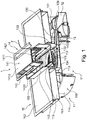
- FIG. 1 is a schematic, perspective sectional view of an embodiment of the extractor device 11 in one embodiment of a combination device 1 is shown.
- the combination device 1 consists of a hob 10 and a fume extractor 11.
- the hob 10 includes a cover plate 102 and a arranged below the cover plate 102 cooktop housing 101.
- heating modules (not shown), such as induction modules, recorded.
- the hob 10 in particular in the cover plate 102 has a recess 103 is introduced.
- the extractor device 11 has a fan (not shown), a fume hood 110 and a filter unit 14.
- the filter unit 14 has two filter elements 140 in the illustrated embodiment.
- the filter elements 140 are held in a filter holder 141.
- the filter holder has a cover 1410, which covers the surface of the recess 103 in the cover plate 102 and are introduced into the two suction openings 1411.
- two filter elements 140 are used in the filter holder 141.
- the filter elements 140 are inclined in the illustrated embodiment at an angle to the horizontal and the vertical.
- the filter holder 141 with the filter elements 140 is inserted into a collecting container 142.
- the collecting container 142 represents an upwardly open trough.
- a passage opening 143 is introduced in the bottom of the collecting container 142.
- the bottom of the collecting container is formed by grooves 1420.
- two grooves 1420 are provided, which extend over the length of the collecting container 142 and are arranged adjacent to the passage opening 143, that is, lie to the right and left of the passage opening 143.
- the passage opening 143 is arranged elevated relative to the grooves 1420 in the collecting container 142.
- overflow openings 1421 are introduced.
- the overflow openings 1421 are at a height which is less than the middle part of the bottom of the collecting container 142 in which the passage opening 143 is located.
- the collecting container 142 has at the upper end a fold 1422 which extends to the outside. By this fold 1422 of the collecting container 142 is held in the recess 103 of the cover plate 102 of the hob 10.
- the extractor housing 110 has a receiving space 111, in which the fan (not shown) of the extractor device 11 is received.
- a receiving space 111 In the top 113 of the extractor housing 110 and in particular of the receiving space 111, which is also referred to as a base, an air inlet opening 112 is introduced.
- the side wall 114 is located at the edge of the upper side.
- the air inlet opening 112 is aligned with the passage opening 143 of the collection container 142 under the filter unit 14.
- a protective grid is provided in the air inlet opening 112. At the edge of the air inlet opening 112, this is surrounded by an annular elevation 132.
- a guide wall 133 on the upper side 113 of the receiving space 111 is provided, which extends upwards.
- the guide wall 133 projects through a distance between two cooktop housings 101 to the underside of the cover plate 102 of the cooktop 10.
- the inflow opening 115 of the extractor housing 110 is defined by the guide wall.
- a guide geometry 134 is formed, which is open at the top. Only through the underside of the grooves 1420 of the collecting container 142, this guide geometry 134 is covered upwards.
- an outlet port 135 is provided at one location.
- a guide channel 130 Adjoining this outlet opening 135 is a guide channel 130, which is preferably an upwardly closed channel which is formed on the upper side 113 of the receiving space 111.
- the guide channel 130 extends laterally beyond the edge of the upper side 113 of the receiving space 111.
- a lid 131 is formed at the end of the guide channel 130, which protrudes laterally beyond the top 113.
- the cover 131 is a component which is closed at the top and on which there is preferably a fastening device 136 for fastening an additional container 12.
- the fastening device 136 represents, for example, an internal thread on the cover 131. From below, an additional container 12 is detachably fastened to the cover 131, in particular screwed over its container neck 120.
- the auxiliary container 12 has a height which corresponds to that of the receiving space 111 of the extractor hood 110.
- the containers 142, 12 and the guide line 13 can be seen more accurately.
- the upper side 113 of the fan accommodating space 111 is inclined to one side.
- the top 113 may be inclined over its entire surface. But it is also possible that only in the region of the outlet opening 135 in the guide wall 133, the surface 113 is inclined.
- the path of liquids in the extractor device 11 is in the FIGS. 1 and 2 indicated by arrows F.
- Air is extracted by the fan (not shown) from the environment, in particular from the hob 10. This air passes through the filter elements 140 of the filter unit 14 and is there freed of impurities, especially water / grease.
- the liquids which are deposited on the filter elements 140 for example by condensation, run downwards on the filter elements 140 and thus reach the bottom of the collecting container 142, in particular into those formed there
- liquid can pass directly from the suction openings 1411 of the filter unit 14 in the cover 1410 to the grooves 1420 of the collecting container 142. This case occurs, for example, when overcooking or spilling food.
- the liquid enters the guide geometry 134, which is formed on the upper side 113 of the receiving space 111 of the extractor housing 110.
- the liquid is passed between the elevation 132, which is provided at the edge of the air inlet opening 112 and the guide wall 133 and thus reaches the outlet opening 135 in the guide wall 133.
- the outlet opening 135 the liquid passes into the guide channel 130 and from there into the auxiliary container 12.
- the flow of the liquid to the additional container 12 is favored by the inclination of the upper side 113 in the region of the guide geometry 134 and the guide channel 130.
- the collecting container 142 with the filter holder 141 can be lifted out of the recess 103 in the cover plate 102 of the hob 10.
- the filter holder 141 is preferably detachable from the collecting container 142
- the filter holder 141 with the filter elements 140 can also be removed in a first step, and then the collecting container 142 can be taken out.
- the guide geometry 134 on the upper side 113 of the receiving space 111 of the extractor housing 11 is accessible through the recess 103 in the cover plate 102 of the hob 10. The user can clean it, especially wipe it. Due to the inclination, the amount of liquid remaining in this guide geometry 143 is small, so that wiping is sufficient.
- the auxiliary container 12 can be removed from below from the fastening device 136 in the lid 131 of the liquid line 13. In a screw cap, the additional container 12 is unscrewed from the internal thread on the lid 131. In the removed state, the additional container 12 can be emptied and cleaned.
- Both the collecting container 142 and the additional container 12 may for example consist of plastic and be cleaned in the dishwasher.
- the present invention has a number of advantages. First, contamination and consequent damage to the extractor device, in particular the fan of the extractor device are reliably prevented. Furthermore, the extractor device has a simple structure and can be easily maintained and cleaned. Finally, in the embodiment in which the auxiliary container is arranged adjacent to a receiving space in the extractor housing for the fan, the overall height is not increased by the inventive liquid supply system.
Abstract
Die Erfindung betrifft eine Dunstabzugsvorrichtung, die einen Lüfter, ein Dunstabzugsgehäuse (110) und eine Filtereinheit (14) aufweist. Die Dunstabzugsvorrichtung (11) ist dadurch gekennzeichnet, dass die Dunstabzugsvorrichtung (11) einen Sammelbehälter (142) für Flüssigkeiten mit mindestens einer Überlauföffnung (1421) und einen Zusatzbehälter (12) für Flüssigkeiten aufweist und zwischen dem Sammelbehälter (142) und dem Zusatzbehälter (12) zumindest bereichsweise eine Flüssigkeitsleitung (13) liegt. Weiterhin wird ein Kombinationsgerät mit einer solchen Dunstabzugsvorrichtung (11) beschrieben.The invention relates to a fume extraction device comprising a fan, a fume hood housing (110) and a filter unit (14). The extractor device (11) is characterized in that the extractor device (11) has a collecting container (142) for liquids with at least one overflow opening (1421) and an additional container (12) for liquids and between the collecting container (142) and the additional container (12 ) at least partially a liquid line (13). Furthermore, a combination device with such a vapor extraction device (11) will be described.
Description
Die vorliegende Erfindung betrifft eine Dunstabzugsvorrichtung und ein Kombinationsgerät mit Dunstabzugsvorrichtung.The present invention relates to a fume extraction device and a combination device with extractor device.
Zum Reinigen von Luft, insbesondere von Dünsten und Wrasen, die beim Kochen auftreten, ist es bekannt, Dunstabzugsvorrichtungen einzusetzen, über die Luft durch einen Filter eingesaugt und an dem Filter gereinigt wird. Dunstabzugsvorrichtungen können als Dunstabzugshaube ausgestaltet sein, die die Luft nach oben einsaugt. Allerdings sind auch Dunstabzugsvorrichtungen bekannt, die die Luft nach unten einsaugen. Diese Dunstabzugsvorrichtungen werden auch als Muldenlüfter bezeichnet. Diese Art von Dunstabzugsvorrichtung kann in oder neben dem Kochfeld angeordnet sein. Die Einströmöffnung, über die Luft in die Dunstabzugsvorrichtung eintritt, liegt dabei in der Horizontalen.For cleaning air, in particular fumes and vapors, which occur during cooking, it is known to use extractor devices, is sucked through the air through a filter and cleaned on the filter. Vapor extraction devices can be designed as an extractor hood, which sucks the air upwards. However, also extractor devices are known which suck the air down. These extractor devices are also referred to as a tray ventilator. This type of extractor device can be arranged in or next to the hob. The inflow opening, via which air enters the extractor device, lies in the horizontal plane.
Ein Problem, das bei dieser Art von Dunstabzugsvorrichtungen auftritt ist, dass Flüssigkeiten entweder von dem Filterelement abtropfen oder auf andere Weise in die Dunstabzugsvorrichtung gelangen können. Dies führt zum einen zur Verunreinigung der Dunstabzugsvorrichtung und kann bei zu großen Mengen von Flüssigkeit auch zur Beschädigung der Dunstabzugsvorrichtung beispielsweise durch Kontakt des Lüfters mit Flüssigkeit führen.One problem that occurs with this type of extractor devices is that liquids may either drip off the filter element or otherwise enter the extractor device. This leads firstly to contamination of the extractor device and can also lead to damage of the extractor device, for example, by contact of the fan with liquid at excessive amounts of liquid.
Aufgabe der vorliegenden Erfindung ist es daher eine Lösung zu schaffen, bei der auf einfache Art und bei einfachem Aufbau der Dunstabzugsvorrichtung der Betrieb und die Sicherheit der Dunstabzugsvorrichtung gewährleistet werden.Object of the present invention is therefore to provide a solution in which the operation and safety of the extractor device are ensured in a simple way and with a simple construction of the extractor device.
Der Erfindung liegt die Erkenntnis zugrunde, dass diese Aufgabe gelöst werden kann, indem an der Dunstabzugsvorrichtung ein Sammelbehälter sowie eine von dem Sammelbehälter wegführende Flüssigkeitsführung bereitgestellt wird, die zu einem Zusatzbehälter führt.The invention is based on the finding that this object can be achieved by providing a collecting container and a liquid guide leading away from the collecting container to the extractor device, which leads to an additional container.
Gemäß einem ersten Aspekt wird die Aufgabe daher gelöst durch eine Dunstabzugsvorrichtung, die einen Lüfter, ein Dunstabzugsgehäuse und eine Filtereinheit aufweist. Die Dunstabzugsvorrichtung ist dadurch gekennzeichnet, dass die Dunstabzugsvorrichtung einen Sammelbehälter für Flüssigkeiten mit mindestens einer Überlauföffnung und einen Zusatzbehälter für Flüssigkeiten aufweist und zwischen dem Sammelbehälter und dem Zusatzbehälter zumindest bereichsweise eine Flüssigkeitsleitung liegt.According to a first aspect, the object is therefore achieved by a fume extraction device having a fan, a fume hood housing and a filter unit. The extractor device is characterized in that the extractor device comprises a collection container for liquids with at least one overflow opening and an additional container for liquids and at least partially a liquid line between the collecting container and the additional container.
Als Dunstabzugsvorrichtung wird eine Vorrichtung bezeichnet, mittels derer verunreinigte Luft, insbesondere Dünste und Wrasen, die beim Kochen entstehen, eingesaugt werden kann. Zur Reinigung der Luft ist in der Dunstabzugsvorrichtung eine Filtereinheit vorgesehen, die vorzugsweise mindestens ein Filterelement aufweist. Die Dunstabzugsvorrichtung weist zudem einen Lüfter und ein Dunstabzugsgehäuse auf. Als Lüfter wird eine aus Lüftermotor und Lüfterrad bestehende Komponente bezeichnet. Der Lüfter stellt vorzugsweise einen Radiallüfter dar.The extractor device is a device by means of which contaminated air, in particular fumes and vapors produced during cooking, can be sucked in. To clean the air, a filter unit is provided in the extractor device, which preferably has at least one filter element. The extractor device also has a fan and a fume hood housing. As a fan consisting of a fan motor and fan component is called. The fan is preferably a radial fan.
Als Dunstabzugsgehäuse wird erfindungsgemäß eine Komponente bezeichnet, in der zumindest der Lüfter der Dunstabzugsvorrichtung aufgenommen ist. Vorzugsweise sind in dem oder an dem Dunstabzugsgehäuse alle für den Betrieb der Dunstabzugsvorrichtung notwendigen Elemente vorgesehen sind. Das Dunstabzugsgehäuse weist vorzugsweise einen Aufnahmeraum für den Lüfter auf. Zudem weist das Dunstabzugsgehäuse vorzugsweise eine Einströmöffnung auf, über die Luft in die Dunstabzugsvorrichtung eintreten kann und in der vorzugsweise die Filtereinheit angeordnet ist. Weiterhin kann in dem Dunstabzugsgehäuse mindestens ein Aufnahmeraum für Elektronikkomponenten, die zum Betreiben des Lüfters dienen, vorgesehen sein.As extractor housing according to the invention a component is referred to, in which at least the fan of the extractor device is added. Preferably, all necessary for the operation of the extractor device elements are provided in or on the extractor housing. The extractor housing preferably has a receiving space for the fan. In addition, the extractor housing preferably has an inflow opening, via which air can enter into the extractor device and in which the filter unit is preferably arranged. Furthermore, at least one receiving space for electronic components which serve to operate the fan can be provided in the extractor housing.
Die Dunstabzugsvorrichtung ist dadurch gekennzeichnet, dass die Dunstabzugsvorrichtung einen Sammelbehälter für Flüssigkeiten und einen Zusatzbehälter für Flüssigkeiten aufweist. Der Sammelbehälter für Flüssigkeiten stellt vorzugsweise einen Behälter dar, in dem zumindest unmittelbar aus einem Filterelement austretende Flüssigkeiten aufgefangen werden können. Die Flüssigkeiten stellen insbesondere Kondensat oder Fett dar. Zudem können in den Sammelbehälter auch weitere Flüssigkeiten beispielsweise Kondensat, das sich an weiteren Teilen der Filtereinheit gebildet hat, oder Flüssigkeiten, die in die Filtereinheit hineinlaufen oder hineintropfen aufgefangen werden. Der Sammelbehälter weist mindestens eine Überlauföffnung auf. Als Überlauföffnung wird hierbei eine Öffnung bezeichnet, die zu dem Boden des Sammelbehälters nach oben versetzt ist aber zu dem oberen Rand des Sammelbehälters nach unten beabstandet ist. Als Zusatzbehälter wird ein Behälter bezeichnet, der vorzugsweise eine größere Aufnahmekapazität als der Sammelbehälter aufweist. Der Zusatzbehälter stellt einen zu dem Sammelbehälter separaten Behälter dar. Vorzugsweise kann Flüssigkeit den Zusatzbehälter nur über den Sammelbehälter erreichen.The extractor device is characterized in that the extractor device comprises a collection container for liquids and an additional container for liquids. The collection container for liquids preferably represents a container in which at least directly from a filter element leaking liquids can be collected. The liquids in particular constitute condensate or fat. In addition, other liquids, for example condensate which has formed on further parts of the filter unit, or liquids which run into the filter unit or drip into it can also be collected in the collecting container. The collecting container has at least one overflow opening. As an overflow opening here is an opening which is offset up to the bottom of the collecting container but is spaced down to the upper edge of the collecting container. As an additional container, a container is referred to, which preferably has a greater absorption capacity than the collecting container. The additional container is a container that is separate from the collecting container. Preferably, liquid can reach the additional container only via the collecting container.
Zwischen dem Sammelbehälter und dem Zusatzbehälter liegt zumindest bereichsweise eine Flüssigkeitsleitung. Als Flüssigkeitsleitung wird eine Vorrichtung oder ein Teil einer Vorrichtung bezeichnet, die geeignet ist Flüssigkeit zu leiten. Die Flüssigkeitsleitung kann aus mehreren Bestandteilen bestehen, wobei einer oder mehrere Bestandteile Hohlkörper darstellen können und einer oder mehrere Bestanteile Rinnen oder offene Kanäle darstellen können.Between the collecting container and the additional container is at least partially a liquid line. A fluid conduit is a device or a part of a device which is suitable for conducting fluid. The liquid line can consist of several components, wherein one or more constituents can represent hollow bodies and one or more constituents can represent channels or open channels.
Indem bei der erfindungsgemäßen Dunstabzugsvorrichtung sowohl ein Sammelbehälter als auch ein Zusatzbehälter vorgesehen sind, kann eine größere Menge an Flüssigkeiten aufgenommen werden, als bei Dunstabzugsvorrichtungen, bei denen lediglich ein Sammelbehälter vorgesehen ist. Hierdurch wird es möglich auch beispielsweise beim Überkochen von Speisen, die gesamte Flüssigkeit, die in die Dunstabzugsvorrichtung eintritt, in den Behältern aufzufangen und so eine Verschmutzung oder Beschädigung weiterer Bestandteile der Dunstabzugsvorrichtung zu verhindern. Indem erfindungsgemäß zusätzlich eine Flüssigkeitsleitung vorgesehen ist, die zumindest einen Bereich zwischen dem Sammelbehälter und dem Zusatzbehälter bildet, kann zum einen ein unkontrolliertes Fließen von Flüssigkeiten zwischen den beiden Behältern verhindert werden. Zudem kann die Position des Zusatzbehälters bezüglich des Sammelbehälters frei gewählt werden. Insbesondere muss der Zusatzbehälter nicht so angeordnet sein, dass Flüssigkeit unmittelbar von dem Sammelbehälter in den Zusatzbehälter tropfen oder überlaufen kann. Eine vertikal übereinander liegende Anordnung der Behälter ist somit nicht erforderlich. Hierdurch wird auch die Bauhöhe der Dunstabzugsvorrichtung verringert.By both a collecting container and an additional container are provided in the extractor device according to the invention, a larger amount of liquids can be received, as in extractor devices, in which only a collecting container is provided. This makes it possible, for example, when overcooking food, catch all the liquid entering the extractor device in the containers and so prevent contamination or damage to other components of the extractor device. According to the invention, in addition, a liquid line is provided which forms at least one region between the collecting container and the additional container, on the one hand an uncontrolled flow of liquids between the two containers can be prevented. In addition, the position of the additional container with respect to the collecting container can be freely selected. In particular, the additional tank need not be arranged so that liquid can drip or overflow directly from the sump into the auxiliary tank. A vertically superimposed arrangement of the container is thus not required. As a result, the height of the extractor device is reduced.
Gemäß einer Ausführungsform ist die Flüssigkeitsleitung zumindest teilweise an dem Dunstabzugsgehäuse gebildet. Insbesondere kann die Flüssigkeitsleitung teilweise durch eine Führungsgeometrie gebildet werden, die an einer Außenseite des Dunstabzugsgehäuses und insbesondere an der Oberseite des Dunstabzugsgehäuses liegt. An dem Dunstabzugsgehäuse ist eine Lufteintrittsöffnung vorgesehen, durch die die Luft in einen in dem Dunstabzugsgehäuse liegenden Aufnahmeraum für einen Lüfter eingesaugt wird. Das Dunstabzugsgehäuse und insbesondere die Lufteintrittsöffnung liegen daher vorzugsweise in oder in der Nähe der Einlassöffnung über die Luft in die Dunstabzugsvorrichtung eingesaugt wird und in der vorzugsweise die Filtereinheit vorgesehen ist. Somit kann durch den Teil der Flüssigkeitsleitung, die zumindest teilweise an dem Dunstabzugsgehäuse gebildet ist, Flüssigkeit in unmittelbarer Nähe zu der Einlassöffnung der Dunstabzugsvorrichtung aufgenommen und geleitet werden. Zudem wird die Teilevielzahl durch das Ausbilden zumindest eines Teils der Flüssigkeitsleitung an dem Dunstabzugsgehäuse reduziert werden.According to one embodiment, the liquid line is at least partially formed on the extractor housing. In particular, the liquid line can be partially formed by a guide geometry which is located on an outer side of the extractor housing and in particular on the upper side of the extractor housing. To the Extractor hood is provided an air inlet opening through which the air is sucked into a lying in the extractor housing receiving space for a fan. The extractor housing and in particular the air inlet opening are therefore preferably in or in the vicinity of the inlet opening is sucked through the air in the extractor device and in which preferably the filter unit is provided. Thus, by the part of the liquid line, which is at least partially formed on the extractor housing, liquid in the immediate vicinity of the inlet opening of the extractor device can be received and directed. In addition, the number of parts will be reduced by forming at least a portion of the liquid line on the extractor housing.
Gemäß einer Ausführungsform ist der Sammelbehälter Teil einer Filtereinheit. Als Filtereinheit wird eine Einheit der Dunstabzugsvorrichtung bezeichnet, die zumindest ein Filterelement umfasst. Vorzugsweise ist in dem Sammelbehälter mindestens ein Filterelement zumindest teilweise aufgenommen. Das Filterelement oder die Filterelemente sind vorzugsweise aus dem Sammelbehälter entnehmbar, das heißt lösbar mit dem Sammelbehälter verbunden oder in diesen eingesetzt. Als zumindest teilweise in dem Sammelbehälter aufgenommen, wird ein Filterelement bezeichnet, bei dem sich zumindest ein Teil des Filterelementes in dem Sammelbehälter befindet. Vorzugsweise liegt das Filterelement zu dem Boden des Sammelbehälters in einem Winkel geneigt in dem Sammelbehälter. Bei dieser Ausführungsform ist zumindest der untere Rand des Filterelementes in dem Sammelbehälter aufgenommen und kann beispielsweise auf dem Boden des Sammelbehälters oder auf einem Vorsprung, der zu dem Boden nach oben versetzt ist, aufliegen.According to one embodiment, the collecting container is part of a filter unit. As a filter unit, a unit of the extractor device is referred to, which comprises at least one filter element. Preferably, at least one filter element is at least partially received in the collecting container. The filter element or the filter elements are preferably removable from the collecting container, that is releasably connected to the collecting container or used in this. As at least partially received in the collecting container, a filter element is referred to, in which at least a part of the filter element is located in the collecting container. Preferably, the filter element is inclined to the bottom of the sump at an angle in the sump. In this embodiment, at least the lower edge of the filter element is received in the sump and may, for example, rest on the bottom of the sump or on a protrusion offset up to the bottom.
Indem das Filterelement zumindest teilweise in dem Sammelbehälter aufgenommen ist, können Flüssigkeiten, die von dem Filterelement ausgefiltert werden beziehungsweise an diesem kondensieren zuverlässig in dem Sammelbehälter aufgefangen werden. Zudem ist die Filtereinheit vorzugsweise im Bereich der Einströmöffnung der Dunstabzugsvorrichtung angeordnet, um dort Verunreinigungen aus der Luft auszufiltern. Somit sind die Filtereinheit und damit auch der Sammelbehälter für den Benutzer zugänglich. Dies ist insbesondere für Reinigungszwecke und Wartungszwecke von Bedeutung.By at least partially accommodating the filter element in the collecting container, liquids which are filtered out of the filter element or condense on it can be reliably collected in the collecting container. In addition, the filter unit is preferably arranged in the region of the inflow opening of the extractor device in order to filter out impurities from the air there. Thus, the filter unit and thus also the collection container are accessible to the user. This is especially important for cleaning and maintenance purposes.
Gemäß einer bevorzugten Ausführungsform ist der Zusatzbehälter lösbar an dem Dunstabzugsgehäuse befestigt. Die lösbare Befestigung kann beispielsweise eine Schraubverbindung, eine Steckverbindung oder eine Rastverbindung sein. Der Vorteil, den die lösbare Verbindung aufweist besteht darin, dass der Zusatzbehälter von der Dunstabzugsvorrichtung abgenommen werden kann. Im abgenommenen Zustand kann der Zusatzbehälter geleert werden. Ein solches Leeren ist insbesondere bei dem Zusatzbehälter von Bedeutung, da dieser vorzugsweise ein größeres Fassungsvermögen als der Sammelbehälter aufweist und ein Reinigen des Zusatzbehälters in dem an der Dunstabzugsvorrichtung befestigten Zustand gegebenenfalls nicht möglich ist.According to a preferred embodiment, the auxiliary container is releasably attached to the extractor housing. The releasable attachment may, for example, a screw, be a plug connection or a locking connection. The advantage of the detachable connection is that the additional container can be removed from the extractor device. When removed, the additional tank can be emptied. Such emptying is particularly important in the additional container, as this preferably has a larger capacity than the sump and a cleaning of the additional container in the state attached to the extractor device state may not be possible.
Vorzugsweise ist an dem Dunstabzugsgehäuse eine Befestigungsvorrichtung für den Zusatzbehälter angeordnet. Die Befestigungsvorrichtung kann an dem Dunstabzugsgehäuse befestigt sein oder einteilig mit dieser gefertigt sein, das heißt angeformt sein. Indem die Befestigungsvorrichtung an dem Dunstabzugsgehäuse angeordnet und vorzugsweise starr an diesem liegt, kann die Position des Zusatzbehälters bezüglich des Dunstabzugsgehäuses festgelegt sein und ein zuverlässiges Führen von Flüssigkeiten zu dem Zusatzbehälter gewährleistet werden. Zudem wird, indem die Befestigungsvorrichtung für den Zusatzbehälter an dem Dunstabzugsgehäuse vorgesehen ist, der Aufbau der Dunstabzugsvorrichtung weiter vereinfacht.Preferably, a fastening device for the additional container is arranged on the extractor housing. The fastening device may be attached to the extractor housing or be made in one piece with this, that is to be molded. By the fastening device is arranged on the extractor housing and preferably rigidly thereto, the position of the additional container with respect to the extractor housing can be defined and a reliable guiding of liquids to the additional container can be ensured. In addition, by the attachment device for the additional container is provided on the extractor housing, the construction of the extractor device further simplified.
Die Befestigungsvorrichtung stellt beispielsweise ein Gewinde dar. Über dieses Gewinde kann ein mit einem entsprechenden Gegengewinde versehener Zusatzbehälter eingeschraubt werden. Den Vorteil, den die Verbindung mittels eines Gewindes aufweist, ist, dass diese zum einen auch ein großes Gewicht tragen kann. Zum anderen ist diese Verbindung zumindest bezüglich Flüssigkeiten dicht. Ein unkontrolliertes Austreten von Flüssigkeiten an der Verbindungsstelle kann daher verhindert werden.The fastening device is, for example, a thread. About this thread a provided with a corresponding mating thread additional container can be screwed. The advantage of having the connection by means of a thread is that it can also carry a great weight on the one hand. On the other hand, this connection is tight at least with regard to liquids. An uncontrolled leakage of liquids at the junction can therefore be prevented.
Gemäß einem weiteren Aspekt betrifft die Erfindung ein Kombinationsgerät umfassend ein Kochfeld und eine Dunstabzugsvorrichtung. Das Kombinationsgerät ist dadurch gekennzeichnet, dass die Dunstabzugsvorrichtung eine erfindungsgemäße Dunstabzugsvorrichtung ist.According to a further aspect, the invention relates to a combination device comprising a hob and a fume extraction device. The combination device is characterized in that the extractor device is an extractor device according to the invention.
Vorteile und Merkmale, die bezüglich der erfindungsgemäßen Dunstabzugsvorrichtung beschrieben wurden, gelten - soweit anwendbar - entsprechend für das erfindungsgemäße Kombinationsgerät und umgekehrt.Advantages and features that have been described with respect to the extractor device according to the invention, apply - where applicable - according to the combination device according to the invention and vice versa.
Das Kombinationsgerät umfasst ein Kochfeld und eine Dunstabzugsvorrichtung. Diese beiden Elemente können über einen gemeinsamen Netzanschluss verfügen und beispielsweise auch von einer gemeinsamen Steuereinheit gesteuert werden.The combination device comprises a hob and a fume extraction device. These two elements can have a common power connection and, for example, be controlled by a common control unit.
Gemäß einer bevorzugten Ausführungsform liegt die Dunstabzugsvorrichtung zumindest bereichsweise unterhalb des Kochfeldes. Die Dunstabzugsvorrichtung kann daher auch als Kochmuldenabzug oder Muldenabzug oder Muldenlüfter bezeichnet werden.According to a preferred embodiment, the extractor device is at least partially below the hob. The extractor device can therefore also be referred to as a cooktop extractor or tray deduction or tray ventilator.
Richtungsangaben, wie oben oder unten beziehen sich - soweit nicht anders angegeben - auf eine Ausführungsform der Dunstabzugsvorrichtung, bei der diese im montierten Zustand zumindest bereichsweise unterhalb eines Kochfeldes angeordnet ist und bei der die Lufteintrittsöffnung des Dunstabzugsgehäuses oben liegt.Directional information, such as above or below relate - unless otherwise stated - to an embodiment of the extractor device, in which it is at least partially arranged in the assembled state below a hob and in which the air inlet opening of the extractor housing is on top.
Bei der Ausführungsform, bei der die Dunstabzugsvorrichtung zumindest teilweise unterhalb des Kochfeldes liegt, können die Vorteile der vorliegenden Erfindung, insbesondere der geringe Bauraum, der für die Dunstabzugsvorrichtung erforderlich ist, besonders gut genutzt werden. Zudem ist bei einem solchen Kombinationsgerät die Wahrscheinlichkeit des Eintretens von Flüssigkeiten in die Dunstabzugsvorrichtung besonders hoch. Mit dem erfindungsgemäßen Kombinationsgerät kann eine Gefahr, die von einem solchen Flüssigkeitseintritt ausgehen kann, minimiert werden und die Reinigung der Dunstabzugsvorrichtung vereinfacht werden.In the embodiment in which the extractor device is at least partially below the hob, the advantages of the present invention, in particular the small space required for the extractor device, can be used particularly well. In addition, in such a combination device, the probability of the entry of liquids into the extractor device is particularly high. With the combination device according to the invention, a risk that may arise from such a liquid inlet can be minimized and the cleaning of the extractor device can be simplified.
Vorzugsweise weist das Dunstabzugsgehäuse einen Aufnahmeraum für einen Lüfter der Dunstabzugsvorrichtung auf und in der Oberseite des Aufnahmeraumes ist eine Lufteintrittsöffnung eingebracht. Der in dem Aufnahmeraum befindliche Lüfter stellt vorzugsweise einen Radiallüfter dar, dessen Lüfterradachse senkrecht zu der Lufteintrittsöffnung liegt.Preferably, the extractor housing has a receiving space for a fan of the extractor device and in the top of the receiving space an air inlet opening is introduced. The fan located in the receiving space preferably represents a radial fan whose fan wheel axis is perpendicular to the air inlet opening.
Gemäß einer Ausführungsform ist an der Oberseite des Dunstabzugsgehäuses eine Führungsgeometrie als Teil der Flüssigkeitsleitung ausgebildet. Vorzugsweise umfasst die Führungsgeometrie eine Erhöhung am Rand der Lufteintrittsöffnung und eine zu der Erhöhung nach außen versetzte Führungswand. Durch die Erhöhung kann zum einen eine verbesserte Luftströmung in die Lufteintrittsöffnung gewährleistet werden. Zum anderen kann die Erhöhung auch zum Schutz gegen ein unkontrolliertes Eintreten von Flüssigkeiten, die sich auf der Oberseite des Dunstabzugsgehäuses befinden, in der die Lufteintrittsöffnung eingebracht ist, dienen. Schließlich ist die Erhöhung Teil der Flüssigkeitsleitung, insbesondere Teil der Führungsgeometrie und bildet mit der Führungswand einen offenen Kanal. Die Führungswand erstreckt sich von der Oberseite des Dunstabzugsgehäuses nach oben. Die Führungswand zusätzlich zur Leitung von Flüssigkeiten beispielsweise auch als Abstandhalter zu einem weiteren Bauteil, insbesondere der Deckplatte des Kochfeldes, dienen. Vorzugsweise erstreckt sich die Führungswand weiter über die Oberseite des Dunstabzugsgehäuses hinaus als die um die Lufteintrittsöffnung vorgesehene Erhöhung. Hierdurch kann in der Führungswand beispielsweise ein Teil der Filtereinheit, insbesondere der Sammelbehälter aufgenommen werden. Die Form der Führungswand ist vorzugsweise der Form der Öffnung in dem Kochfeld und der Filtereinheit angepasst und kann beispielsweise eine rechteckig umlaufende Wand darstellen.According to one embodiment, a guide geometry is formed as part of the liquid line at the top of the extractor housing. Preferably, the guide geometry comprises an increase at the edge of the air inlet opening and an outwardly offset to the increase guide wall. By increasing on the one hand, an improved air flow can be ensured in the air inlet opening. On the other hand, the increase can also be used to protect against uncontrolled entry of liquids located on top of the extractor housing, in which the air inlet opening is introduced, serve. Finally, the increase is part of the fluid line, in particular part of the guide geometry and forms an open channel with the guide wall. The guide wall extends upwardly from the top of the extractor housing. The guide wall in addition to the management of liquids, for example, as a spacer to another component, in particular the cover plate of the hob, serve. Preferably, the guide wall extends further beyond the top of the extractor housing than the increase provided around the air inlet opening. As a result, for example, part of the filter unit, in particular the collecting container, can be received in the guide wall. The shape of the guide wall is preferably adapted to the shape of the opening in the hob and the filter unit and may for example represent a rectangular circumferential wall.
Gemäß einer Ausführungsform umfasst die Flüssigkeitsleitung einen Führungskanal. Als Führungskanal wird insbesondere ein Kanal mit einem durchgehenden Querschnitt, beispielsweise einem rechteckigen Querschnitt bezeichnet. Der Führungskanal kann daher auch als geschlossener Kanal bezeichnet werden. Die Unterseite des Führungskanals kann zumindest über einen Teil seiner Länge durch die Oberseite des Dunstabzugsgehäuses gebildet werden. Auf der Oberseite ist dann ein Tunnel aufgebracht oder angeformt, der den Kanal nach oben abdeckt. Indem ein Führungskanal verwendet wird, kann ein Austreten von Flüssigkeit nach oben verhindert werden. Bei der Ausführungsform der Dunstabzugsvorrichtung, bei der eine Führungswand auf der Oberseite des Dunstabzugsgehäuse angeordnet ist, befindet sich der Führungskanal vorzugsweise außerhalb der Führungswand und in der Führungswand ist eine Auslassöffnung vorgesehen, durch die der Führungskanal mit der innerhalb der von der Führungswand begrenzten Raum liegenden Führungsgeometrie verbunden ist.According to one embodiment, the liquid line comprises a guide channel. As a guide channel in particular a channel is referred to with a continuous cross section, for example a rectangular cross section. The guide channel can therefore also be referred to as a closed channel. The underside of the guide channel can be formed at least over part of its length through the top of the extractor housing. On top of a tunnel is then applied or molded, which covers the channel upwards. By using a guide channel, leakage of liquid upwards can be prevented. In the embodiment of the extractor device, in which a guide wall is arranged on the upper side of the extractor housing, the guide channel is preferably outside the guide wall and in the guide wall, an outlet opening is provided, through which the guide channel with the within the bounded by the guide wall space geometry connected is.
Vorzugsweise erstreckt sich der Führungskanal über den äußeren Rand des Aufnahmeraumes des Dunstabzugsgehäuses hinaus. Als äußerer Rand des Aufnahmeraumes wird insbesondere der Rand in radialer Richtung, das heißt in der Richtung des Radius des in dem Aufnahmeraum vorzusehenden Lüfterrades, verstanden. Da das Dunstabzugsgehäuse vorzugsweise so angeordnet ist, dass die Achse des Lüfterrades senkrecht zu der Lufteintrittsöffnung liegt und die Lufteintrittsöffnung in der Nähe der Einströmöffnung liegt, kann bei der Ausführungsform, bei der sich der Führungskanal über den äußeren Rand des Aufnahmeraumes erstreckt, der Zusatzbehälter an dem Ende des Führungskanals und damit neben dem Aufnahmeraum angeordnet werden.Preferably, the guide channel extends beyond the outer edge of the receiving space of the extractor housing. In particular, the edge in the radial direction, that is to say in the direction of the radius of the fan wheel to be provided in the receiving space, is understood as the outer edge of the receiving space. Since the extractor housing is preferably arranged so that the axis of the fan wheel is perpendicular to the air inlet opening and the air inlet opening is located in the vicinity of the inflow opening, in the embodiment in which the guide channel over the outer edge extends the receiving space, the additional container at the end of the guide channel and thus be arranged next to the receiving space.
Gemäß einer Ausführungsform liegt am äußeren Ende des Führungskanals eine Befestigungsvorrichtung für den Zusatzbehälter. Indem der Zusatzbehälter an dem Führungskanal befestigt werden kann, ist ein freies Verteilen der Flüssigkeit im Inneren des Kombinationsgerätes ausgeschlossen. Die Befestigungsvorrichtung kann beispielsweise ein nach oben abgeschlossenes Gewinde mit einem Einlass für Flüssigkeiten aus dem Führungskanal sein.According to one embodiment lies at the outer end of the guide channel, a fastening device for the additional container. By the additional container can be attached to the guide channel, a free distribution of the liquid inside the combination device is excluded. The attachment device may be, for example, an upwardly threaded closure with an inlet for liquids from the guide channel.
Gemäß einer Ausführungsform ist die Befestigungsvorrichtung für den Zusatzbehälter zu dem Aufnahmeraum des Dunstabzugsgehäuses für den Lüfter benachbart. In dem Aufnahmeraum ist der Lüfter der Dunstabzugsvorrichtung angeordnet. In der Oberseite des Aufnahmeraumes ist eine Lufteintrittsöffnung eingebracht. Indem an der Dunstabzugsvorrichtung die Befestigungsvorrichtung für den Zusatzbehälter benachbart zu dem Aufnahmeraum vorgesehen ist, kann der Zusatzbehälter neben dem Aufnahmeraum gehalten werden. Der Raum oberhalb der Lufteintrittsöffnung wird daher für den Zusatzbehälter nicht benötigt und die Gesamthöhe der Dunstabzugsvorrichtung damit verringert.According to one embodiment, the attachment device for the auxiliary container is adjacent to the receiving space of the extractor housing for the fan. In the receiving space of the fan of the extractor device is arranged. In the top of the receiving space an air inlet opening is introduced. By the attachment device for the additional container adjacent to the receiving space is provided on the extractor device, the additional container can be kept next to the receiving space. The space above the air inlet opening is therefore not required for the additional container and thus reduces the overall height of the extractor device.
Gemäß einer bevorzugten Ausführungsform wird der Sammelbehälter lösbar in dem Kochfeld gehalten. Zu diesem Zweck ist vorzugsweise in einer Deckplatte des Kochfeldes eine Aussparung eingebracht. In diese Aussparung kann der Sammelbehälter eingesetzt werden. Vorzugsweise ist der Sammelbehälter nach oben abnehmbar. In dem Sammelbehälter kann das oder können die Filterelemente der Filtereinheit zumindest teilweise aufgenommen sein. In diesem Fall kann der Sammelbehälter auch als Teil der Filtereinheit bezeichnet werden. Indem der Sammelbehälter lösbar ist, kann der Sammelbehälter zu Reinigungszwecken entnommen werden. Indem der Sammelbehälter insbesondere nach oben von dem Kochfeld abnehmbar ist, kann der Sammelbehälter von dem Kochfeld durch Anheben entnommen werden, ohne, dass ein Auslaufen von in dem Sammelbehälter befindlicher Flüssigkeit zu befürchten ist.According to a preferred embodiment, the sump is releasably held in the hob. For this purpose, a recess is preferably introduced in a cover plate of the hob. In this recess, the sump can be used. Preferably, the sump is removable upwards. The filter element or the filter elements of the filter unit can be at least partially accommodated in the collecting container. In this case, the collection container may also be referred to as part of the filter unit. By the collecting container is detachable, the collecting container can be removed for cleaning purposes. By the collecting container is particularly removable from the top of the hob, the collecting container can be removed from the hob by lifting, without that leakage of liquid in the container is to be feared.
Gemäß einer weiteren Ausführungsform ist der Zusatzbehälter von unten von der Dunstabzugsvorrichtung und insbesondere von dem Dunstabzugsgehäuse abnehmbar. Diese Ausführungsform ist vorteilhaft, da der Zusatzbehälter aufgrund seines vorzugsweise größeren Fassungsvermögens ein großes Gewicht aufweisen kann. Ein Absenken eines solchen Zusatzbehälters beim Abnehmen des Zusatzbehälters ist daher für den Benutzer einfacher möglich als ein Anheben.According to a further embodiment, the additional container is removable from below from the extractor device and in particular from the extractor housing. This embodiment is advantageous because the additional container due to its preferably larger Capacity can have a large weight. Lowering of such an additional container when removing the additional container is therefore easier for the user than lifting.
Gemäß einer bevorzugten Ausführungsform weist die Oberseite des Dunstabzugsgehäuses zumindest im Bereich der Flüssigkeitsleitung eine Neigung aus der Horizontalen heraus auf. Durch diese Ausgestaltung kann das Abfließen der Flüssigkeit zu einem Zusatzbehälter, der vorzugsweise benachbart zu dem Dunstabzugsgehäuse angeordnet ist, gewährleistet werden.According to a preferred embodiment, the upper side of the extractor housing, at least in the region of the liquid line, has an inclination out of the horizontal. As a result of this embodiment, the outflow of the liquid to an additional container, which is preferably arranged adjacent to the extractor housing, can be ensured.
Das Kombinationsgerät kann in einer Ausführungsform außerdem Kochfeld, in dem vorzugsweise eine Aussparung eingebracht ist, eine Dunstabzugsvorrichtung aufweisen, die ein Dunstabzugsgehäuse aufweist. Auf der Oberseite des Dunstabzugsgehäuses kann eine Führungsgeometrie als Teil der Flüssigkeitsleitung ausgebildet sein, die in einen Führungskanal übergeht, der sich über einen äußeren Rand des Dunstabzugsgehäuses erstreckt. Am Ende des Führungskanals kann eine Befestigungsvorrichtung für den Zusatzbehälter liegen und der Sammelbehälter kann auf die Führungsgeometrie aufgesetzt sein und die Überlauföffnung des Sammelbehälters ist mit einem Teil der Führungsgeometrie ausgerichtet. Insbesondere ist die Überlauföffnung so mit der Führungsgeometrie ausgerichtet, das Flüssigkeit, die aus dem Sammelbehälter austritt, in die Führungsgeometrie läuft und beispielsweise von oben in einen offenen Kanal der Führungsgeometrie tropft.In one embodiment, the combination device can also have a cooking hob, in which a recess is preferably made, having a fume extraction device which has a fume hood housing. On the top of the extractor housing, a guide geometry may be formed as part of the fluid conduit which merges into a guide channel extending over an outer edge of the extractor housing. At the end of the guide channel may be a fastening device for the additional container and the collecting container may be placed on the guide geometry and the overflow opening of the collecting container is aligned with a part of the guide geometry. In particular, the overflow opening is aligned with the guide geometry, the liquid that emerges from the collection runs in the guide geometry and drips, for example, from above into an open channel of the guide geometry.
Gemäß einer Ausführungsform der vorliegenden Erfindung wird somit ein Kombinationsgerät, das auch als Gerät bezeichnet werden kann, bereitgestellt, das aus einem Kochfeld mit integrierter Dunstabzugsvorrichtung, die auch als Lüftungseinheit bezeichnet werden kann, besteht. In dem Kombinationsgerät, wird ein System eingebaut, das Kondensat oder andere Flüssigkeiten sammelt. Im normalen Betrieb des Kombinationsgerätes wird Kondensat aufgefangen, das sich beispielsweise an den Filterelementen der Dunstabzugsvorrichtung niederschlägt. Insbesondere wird beim Kochen wird Dampf/Fett-Wrasen generiert, der in den meisten Fällen zu Kondensation in dem Bereich der Einströmöffnung, die auch als Ansaugzone bezeichnet werden kann, der Dunstabzugsvorrichtung führt. Im schlechtesten Fall wird Überlaufflüssigkeit aufgefangen, wenn beispielsweise eine größere Menge Wasser auf dem Kochfeld oder in die Ansaugzone verschüttet wurde.Thus, according to one embodiment of the present invention, a combination device, which may also be referred to as a device, is provided which consists of a cooktop with an integrated extractor device, which may also be referred to as a ventilation unit. In the combination unit, a system is installed that collects condensate or other liquids. In normal operation of the combination device condensate is collected, which is reflected for example on the filter elements of the extractor device. In particular, during cooking, steam / fat vapor is generated, which in most cases leads to condensation in the region of the inflow opening, which can also be referred to as suction zone, of the extractor device. In the worst case, overflow liquid is collected if, for example a larger amount of water was spilled on the hob or in the suction zone.
Erfindungsgemäß kann Kondensat, das im Normalbetrieb des Kombinationsgerätes auftritt, in dem Sammelbehälter, der einen ersten Behälter darstellt, gesammelt werden. Dieser erste Behälter hat eine begrenzte Kapazität. Zudem bietet der Sammelbehälter eine Überlauffunktion an. Ist eine größere Menge von Flüssigkeit aufzunehmen, läuft diese in den Zusatzbehälter, der der eine größere Kapazität bietet.According to the invention, condensate which occurs during normal operation of the combination device can be collected in the collecting container, which constitutes a first container. This first container has a limited capacity. In addition, the sump offers an overflow function. If a larger amount of liquid is to be taken up, it will run into the additional tank, which offers a larger capacity.
Der Sammelbehälter kann von oben vom Kunden entfernt werden zum Entleeren und zur Reinigung und ist spülmaschinenbeständig. Der Zusatzbehälter hat eine größere Kapazität und ist von unten abnehmbar zum Entleeren und zur Reinigung und ist ebenfalls spülmaschinengeeignet.The sump can be removed from above by the customer for emptying and cleaning and is dishwasher safe. The additional container has a larger capacity and is removable from below for emptying and cleaning and is also dishwasher safe.
Die vorliegende Erfindung wird im Folgenden erneut unter Bezugnahme auf die beiliegenden Zeichnungen erläutert es zeigen:
- Figur 1
- eine schematische, perspektivische Schnittansicht einer Ausführungsform der Dunstabzugsvorrichtung in einer Ausführungsform eines Kombinationsgerätes in Explosionsdarstellung; und
- Figur 2
- eine schematische Detailschnittansicht der Behälter in der Ausführungsform nach
Figur 1 .
- FIG. 1
- a schematic, perspective sectional view of an embodiment of the extractor device in an embodiment of a combination device in an exploded view; and
- FIG. 2
- a schematic detail sectional view of the container in the embodiment according to
FIG. 1 ,
In
Die Dunstabzugsvorrichtung 11 weist einen Lüfter (nicht gezeigt), ein Dunstabzugsgehäuse 110 und eine Filtereinheit 14 auf.The
Die Filtereinheit 14 weist in der dargestellten Ausführungsform zwei Filterelemente 140 auf. Die Filterelemente 140 sind in einem Filterhalter 141 gehalten. In der dargestellten Ausführungsform weist der Filterhalter eine Abdeckung 1410 auf, die die Fläche der Aussparung 103 in der Deckplatte 102 abdeckt und in die zwei Einsaugöffnungen 1411 eingebracht sind. In dem Filterhalter 141 sind zwei Filterelemente 140 eingesetzt. Die Filterelemente 140 stehen in der dargestellten Ausführungsform in einem Winkel zu der Horizontalen und der Vertikalen geneigt. Der Filterhalter 141 mit den Filterelementen 140 ist in einen Sammelbehälter 142 eingesetzt. der Sammelbehälter 142 stellt eine nach oben offene Wanne dar. In dem Boden des Sammelbehälters 142 ist eine Durchlassöffnung 143 eingebracht. Um die Durchlassöffnung 143 herum wird der Boden des Sammelbehälters durch Rinnen 1420 gebildet. In der dargestellten Ausführungsform sind zwei Rinnen 1420 vorgesehen, die sich über die Länge des Sammelbehälters 142 erstrecken und zu der Durchlassöffnung 143 benachbart angeordnet sind, das heißt rechts und links von der Durchlassöffnung 143 liegen. Die Durchlassöffnung 143 ist gegenüber den Rinnen 1420 erhöht in dem Sammelbehälter 142 angeordnet. An einer oder beiden Stirnseiten des Sammelbehälters 142 sind Überlauföffnungen 1421 eingebracht. Die Überlauföffnungen 1421 liegen auf einer Höhe, die geringer ist als der mittlere Teil des Bodens des Sammelbehälters 142 in dem die Durchlassöffnung 143 liegt.The
Der Sammelbehälter 142 weist am oberen Ende eine Abkantung 1422, die sich nach außen erstreckt, auf. Durch diese Abkantung 1422 wird der Sammelbehälter 142 in der Aussparung 103 der Deckplatte 102 des Kochfeldes 10 gehalten.The collecting
Unterhalb des Sammelbehälters 142 liegt das Dunstabzugsgehäuse 110 der Dunstabzugsvorrichtung 11. Das Dunstabzugsgehäuse 110 weist einen Aufnahmeraum 111 auf, in dem der Lüfter (nicht gezeigt) der Dunstabzugsvorrichtung 11 aufgenommen wird. In der Oberseite 113 des Dunstabzugsgehäuses 110 und insbesondere des Aufnahmeraumes 111, die auch als Grundfläche bezeichnet wird, ist eine Lufteintrittsöffnung 112 eingebracht. Am Rand der Oberseite befindet sich die Seitenwand 114. Die Lufteintrittsöffnung 112 liegt zu der Durchlassöffnung 143 des Sammelbehälters 142 ausgerichtet unter der Filtereinheit 14. In der dargestellten Ausführungsform ist in der Lufteintrittsöffnung 112 ein Schutzgitter vorgesehen. Am Rand der Lufteintrittsöffnung 112 wird diese von einer ringförmigen Erhöhung 132 umgeben. Zu der Lufteintrittsöffnung 112 und der Erhöhung 132 nach außen versetzt ist eine Führungswand 133 auf der Oberseite 113 des Aufnahmeraumes 111 vorgesehen, die sich nach oben erstreckt. Die Führungswand 133 ragt durch einen Abstand zwischen zwei Kochfeldgehäusen 101 bis zur Unterseite der Deckplatte 102 des Kochfeldes 10. Durch die Führungswand wird somit die Einströmöffnung 115 des Dunstabzugsgehäuses 110 definiert. Durch die Führungswand 133 zum einen und die Erhöhung 132 um die Lufteintrittsöffnung 112 zum anderen wird eine Führungsgeometrie 134 gebildet, die nach oben offen ist. Lediglich durch die Unterseite der Rinnen 1420 des Sammelbehälters 142 ist diese Führungsgeometrie 134 nach oben abgedeckt. In der Führungswand 133 ist an einer Stelle, eine Auslassöffnung 135 vorgesehen. An diese Auslassöffnung 135 schließt sich ein Führungskanal 130 an, der vorzugsweise ein nach oben geschlossener Kanal ist, der auf der Oberseite 113 des Aufnahmeraums 111 gebildet ist. Der Führungskanal 130 ragt über den Rand der Oberseite 113 des Aufnahmeraumes 111 seitlich hinaus. An dem Ende des Führungskanals 130, das über die Oberseite 113 seitlich hinausragt, ist ein Deckel 131 angeformt. Der Deckel 131 ist ein Bauteil, das nach oben geschlossen ist und an dem vorzugsweise eine Befestigungsvorrichtung 136 zur Befestigung eines Zusatzbehälters 12 vorliegt.Below the collecting
Die Befestigungsvorrichtung 136 stellt beispielsweise ein Innengewinde an dem Deckel 131 dar. Von unten ist ein Zusatzbehälter 12 an dem Deckel 131 lösbar befestigt, insbesondere über dessen Behälterhals 120 angeschraubt. Der Zusatzbehälter 12 weist eine Höhe auf, die der des Aufnahmeraumes 111 des Dunstabzugsgehäuses 110 entspricht.The
In
Der Weg von Flüssigkeiten in der Dunstabzugsvorrichtung 11 ist in den
Sobald der Flüssigkeitspegel in den Rinnen 1420 eine Höhe erreicht hat, die der Höhe entspricht, in der die Überlauföffnungen 1421 in dem Sammelbehälter 142 eingebracht sind, läuft Flüssigkeit von dem Sammelbehälter 142 nach unten. Dort gelangt die Flüssigkeit in die Führungsgeometrie 134, die auf der Oberseite 113 des Aufnahmeraumes 111 des Dunstabzugsgehäuses 110 gebildet ist. Insbesondere wird die Flüssigkeit zwischen der Erhöhung 132, die am Rand der Lufteintrittsöffnung 112 vorgesehen ist und der Führungswand 133 geleitet und erreicht so die Auslassöffnung 135 in der Führungswand 133. Durch diese Auslassöffnung 135 gelangt die Flüssigkeit in den Führungskanal 130 und von dort in den Zusatzbehälter 12. Das Fließen der Flüssigkeit zu dem Zusatzbehälter 12 wird durch die Neigung der Oberseite 113 im Bereich der Führungsgeometrie 134 und des Führungskanals 130 begünstigt.As soon as the liquid level in the
Ein Austreten der Flüssigkeit aus der Führungsgeometrie 134 über die Erhöhung 132 zu der Lufteintrittsöffnung 112 wird durch den Sammelbehälter 142 verhindert. Dieser kann mit der Durchlassöffnung 143 oder an der Unterseite des Sammelbehälters 142 zusätzlich vorgesehene Dichtelemente, beispielsweise Dichtstegen (nicht gezeigt), auf der Erhöhung 132 aufliegen und so ein Übertreten von Flüssigkeit verhindern.Leakage of the liquid from the
Zur Reinigung kann der Sammelbehälter 142 mit dem Filterhalter 141 aus der Aussparung 103 in der Deckplatte 102 des Kochfeldes 10 herausgehoben werden. Da der Filterhalter 141 aber vorzugsweise lösbar zu dem Sammelbehälter 142 ist kann auch in einem ersten Schritt der Filterhalter 141 mit den Filterelementen 140 entnommen werden und anschließend der Sammelbehälter 142 herausgenommen werden. Bei entnommenem Sammelbehälter 142 ist die Führungsgeometrie 134 auf der Oberseite 113 des Aufnahmeraumes 111 des Dunstabzugsgehäuses 11 durch die Aussparung 103 in der Deckplatte 102 des Kochfeldes 10 zugänglich. Der Benutzer kann diese damit reinigen, insbesondere abwischen. Aufgrund der Neigung ist der Betrag an Flüssigkeit, der in dieser Führungsgeometrie 143 verbleibt, gering, so dass ein Abwischen ausreichend ist.For cleaning, the collecting
Der Zusatzbehälter 12 kann von unten aus der Befestigungsvorrichtung 136 in dem Deckel 131 der Flüssigkeitsleitung 13 herausgenommen werden. Bei einem Schraubverschluss wird der Zusatzbehälter 12 aus dem Innengewinde an dem Deckel 131 herausgedreht. Im entnommenen Zustand kann der Zusatzbehälter 12 geleert und gereinigt werden.The
Sowohl der Sammelbehälter 142 als auch der Zusatzbehälter 12 können beispielsweise aus Kunststoff bestehen und in der Spülmaschine gereinigt werden.Both the collecting
Die vorliegende Erfindung weist eine Reihe von Vorteilen auf. Zum einen sind eine Verunreinigung und eine dadurch bedingte Beschädigung der Dunstabzugsvorrichtung, insbesondere des Lüfters der Dunstabzugsvorrichtung zuverlässig verhindert. Weiterhin weist die Dunstabzugsvorrichtung einen einfachen Aufbau auf und kann auf einfache Weise gewartet und gereinigt werden. Schließlich ist bei der Ausführungsform, bei der der Zusatzbehälter zu einem Aufnahmeraum in dem Dunstabzugsgehäuse für den Lüfter benachbart angeordnet ist, die Bauhöhe durch das erfindungsgemäße Flüssigkeitsführungssystem nicht vergrößert.The present invention has a number of advantages. First, contamination and consequent damage to the extractor device, in particular the fan of the extractor device are reliably prevented. Furthermore, the extractor device has a simple structure and can be easily maintained and cleaned. Finally, in the embodiment in which the auxiliary container is arranged adjacent to a receiving space in the extractor housing for the fan, the overall height is not increased by the inventive liquid supply system.
- 11
- Kombinationsgerätcombination device
- 1010
- Kochfeldhob
- 101101
- KochfeldgehäuseHob housing
- 102102
- Deckplattecover plate
- 103103
- Aussparungrecess
- 1111
- DunstabzugsvorrichtungExhaust hood
- 110110
- DunstabzugsgehäuseExtractor housing
- 111111
- Aufnahmeraumaccommodation space
- 112112
- LufteintrittsöffnungAir inlet opening
- 113113
- Oberseitetop
- 114114
- SeitenwandSide wall
- 115115
- Einströmöffnunginflow
- 1212
- Zusatzbehälteradditional container
- 120120
- Behälterhalscontainer neck
- 1313
- Flüssigkeitsleitungliquid line
- 130130
- Führungskanalguide channel
- 131131
- Deckelcover
- 132132
- Erhöhungincrease
- 133133
- Führungswandguide wall
- 134134
- Führungsgeometrieguide geometry
- 135135
- Auslassöffnungoutlet
- 136136
- Befestigungsvorrichtungfastening device
- 1414
- Filtereinheitfilter unit
- 140140
- Filterelementfilter element
- 141141
- Filterhalterfilter holder
- 14101410
- Abdeckungcover
- 14111411
- EinsaugöffnungIntake vent
- 142142
- SammelbehälterClippings
- 14201420
- Rinnegutter
- 14211421
- ÜberlauföffnungOverflow opening
- 14221422
- Abkantungfold
- 143143
- DurchlassöffnungPort
Claims (13)
Applications Claiming Priority (1)
| Application Number | Priority Date | Filing Date | Title |
|---|---|---|---|
| EP16290159 | 2016-08-26 |
Publications (2)
| Publication Number | Publication Date |
|---|---|
| EP3290813A1 true EP3290813A1 (en) | 2018-03-07 |
| EP3290813B1 EP3290813B1 (en) | 2019-11-20 |
Family
ID=56893907
Family Applications (1)
| Application Number | Title | Priority Date | Filing Date |
|---|---|---|---|
| EP17186265.9A Active EP3290813B1 (en) | 2016-08-26 | 2017-08-15 | Fume extraction device and combination device with fume extraction device |
Country Status (1)
| Country | Link |
|---|---|
| EP (1) | EP3290813B1 (en) |
Cited By (4)
| Publication number | Priority date | Publication date | Assignee | Title |
|---|---|---|---|---|
| CN110578943A (en) * | 2018-06-08 | 2019-12-17 | Bsh家用电器有限公司 | Smoke evacuation device and combination device with smoke evacuation device and cooking hob |
| EP3951270A1 (en) * | 2020-08-05 | 2022-02-09 | Electrolux Appliances Aktiebolag | Combination appliance |
| EP4043799A1 (en) | 2021-02-16 | 2022-08-17 | Electrolux Appliances Aktiebolag | Extractor hood for a hob and method for operating an extractor hood |
| EP4063747A1 (en) * | 2021-03-26 | 2022-09-28 | Emc Fime S.R.L. | Suction unit for cooking hobs |
Citations (6)
| Publication number | Priority date | Publication date | Assignee | Title |
|---|---|---|---|---|
| DE2641708A1 (en) * | 1976-09-16 | 1978-03-30 | Paul Gutermuth | DAMP ROOM CEILING |
| US5537988A (en) * | 1995-08-21 | 1996-07-23 | Sung-Lin Huang | Grease guiding tray for a kitchen ventilator |
| US5975075A (en) * | 1997-10-07 | 1999-11-02 | Haiki Co., Ltd. | Exhauster for cooking |
| US6041774A (en) * | 1998-11-13 | 2000-03-28 | Evs, Inc. | Overhead ventilation system for use with a cooking appliance |
| US20050279345A1 (en) * | 2004-06-16 | 2005-12-22 | Fu Chang Y | Grease guiding structure for a kitchen ventilator |
| DE102013007722A1 (en) * | 2013-05-07 | 2014-11-13 | Exklusiv-Hauben Gutmann Gmbh | Trough ventilation for extracting cooking vapors from a hob |
-
2017
- 2017-08-15 EP EP17186265.9A patent/EP3290813B1/en active Active
Patent Citations (6)
| Publication number | Priority date | Publication date | Assignee | Title |
|---|---|---|---|---|
| DE2641708A1 (en) * | 1976-09-16 | 1978-03-30 | Paul Gutermuth | DAMP ROOM CEILING |
| US5537988A (en) * | 1995-08-21 | 1996-07-23 | Sung-Lin Huang | Grease guiding tray for a kitchen ventilator |
| US5975075A (en) * | 1997-10-07 | 1999-11-02 | Haiki Co., Ltd. | Exhauster for cooking |
| US6041774A (en) * | 1998-11-13 | 2000-03-28 | Evs, Inc. | Overhead ventilation system for use with a cooking appliance |
| US20050279345A1 (en) * | 2004-06-16 | 2005-12-22 | Fu Chang Y | Grease guiding structure for a kitchen ventilator |
| DE102013007722A1 (en) * | 2013-05-07 | 2014-11-13 | Exklusiv-Hauben Gutmann Gmbh | Trough ventilation for extracting cooking vapors from a hob |
Cited By (7)
| Publication number | Priority date | Publication date | Assignee | Title |
|---|---|---|---|---|
| CN110578943A (en) * | 2018-06-08 | 2019-12-17 | Bsh家用电器有限公司 | Smoke evacuation device and combination device with smoke evacuation device and cooking hob |
| CN110578943B (en) * | 2018-06-08 | 2024-02-06 | Bsh家用电器有限公司 | Smoke discharge device and combined equipment with smoke discharge device and cooking bench |
| EP3951270A1 (en) * | 2020-08-05 | 2022-02-09 | Electrolux Appliances Aktiebolag | Combination appliance |
| WO2022028968A1 (en) * | 2020-08-05 | 2022-02-10 | Electrolux Appliances Aktiebolag | Combination appliance comprising a cooking hob and an extraction device |
| EP4043799A1 (en) | 2021-02-16 | 2022-08-17 | Electrolux Appliances Aktiebolag | Extractor hood for a hob and method for operating an extractor hood |
| WO2022175082A1 (en) | 2021-02-16 | 2022-08-25 | Electrolux Appliances Aktiebolag | Extractor hood for a hob and method for operating an extractor hood |
| EP4063747A1 (en) * | 2021-03-26 | 2022-09-28 | Emc Fime S.R.L. | Suction unit for cooking hobs |
Also Published As
| Publication number | Publication date |
|---|---|
| EP3290813B1 (en) | 2019-11-20 |
Similar Documents
| Publication | Publication Date | Title |
|---|---|---|
| EP3290813B1 (en) | Fume extraction device and combination device with fume extraction device | |
| DE102008012961B4 (en) | Cooking device with a Wrasenkondensiereinrichtung | |
| EP3338030B1 (en) | Combined device with cooking hob and vapour extraction device with filter unit | |
| DE3215812C2 (en) | ||
| EP3136004B1 (en) | Combination device with a cooker hob and extractor device | |
| EP3133349B1 (en) | Combination device with cooking hob and extractor device with filter unit | |
| EP3133350B1 (en) | Combination device with cooking hob and extractor device with filter unit | |
| WO2017080781A1 (en) | Filter device for a steam extraction device and steam extraction device | |
| EP3614053B1 (en) | Vapour extraction device and combination device with vapour extraction device and hob | |
| DE202016104283U1 (en) | Device for filtering fumes and vapors from cooking | |
| EP3701192A1 (en) | Combination appliance with fume extraction device and cooktop | |
| EP3336438B1 (en) | Extractor hood | |
| WO2020152288A1 (en) | Fume extractor device for a hob, and combined appliance | |
| DE102009002225A1 (en) | Steam guide plate for filter unit of extractor hood, has inlet opening for admission of impurities, which are deposited at lower side of plate, into plate interior, where part of lower side of vacuuming zone forms guide to guide impurities | |
| EP3789681A1 (en) | Vapour extraction device and combination apparatus | |
| DE102011109282A1 (en) | Cooking device with fat drain | |
| EP3722677A1 (en) | Vapour extraction device and combination device with cooking hob and vapour extraction device | |
| EP3222919B1 (en) | Extractor hood with viewing cover and inner element | |
| DE102017200201A1 (en) | Extractor and combination device with extractor | |
| DE102014108237A1 (en) | Hood | |
| EP3346195B1 (en) | Extractor hood and filter element for an extractor hood | |
| EP3504482B1 (en) | Combination device including a cooktop and an extractor hood | |
| DE102020210578A1 (en) | Extractor device and combination device | |
| DE102015202838A1 (en) | Extractor hood with sump | |
| DE4209297C2 (en) | Treatment facility for the clean room area |
Legal Events
| Date | Code | Title | Description |
|---|---|---|---|
| PUAI | Public reference made under article 153(3) epc to a published international application that has entered the european phase |
Free format text: ORIGINAL CODE: 0009012 |
|
| STAA | Information on the status of an ep patent application or granted ep patent |
Free format text: STATUS: THE APPLICATION HAS BEEN PUBLISHED |
|
| AK | Designated contracting states |
Kind code of ref document: A1 Designated state(s): AL AT BE BG CH CY CZ DE DK EE ES FI FR GB GR HR HU IE IS IT LI LT LU LV MC MK MT NL NO PL PT RO RS SE SI SK SM TR |
|
| AX | Request for extension of the european patent |
Extension state: BA ME |
|
| STAA | Information on the status of an ep patent application or granted ep patent |
Free format text: STATUS: REQUEST FOR EXAMINATION WAS MADE |
|
| 17P | Request for examination filed |
Effective date: 20180907 |
|
| RBV | Designated contracting states (corrected) |
Designated state(s): AL AT BE BG CH CY CZ DE DK EE ES FI FR GB GR HR HU IE IS IT LI LT LU LV MC MK MT NL NO PL PT RO RS SE SI SK SM TR |
|
| GRAP | Despatch of communication of intention to grant a patent |
Free format text: ORIGINAL CODE: EPIDOSNIGR1 |
|
| STAA | Information on the status of an ep patent application or granted ep patent |
Free format text: STATUS: GRANT OF PATENT IS INTENDED |
|
| INTG | Intention to grant announced |
Effective date: 20190710 |
|
| GRAA | (expected) grant |
Free format text: ORIGINAL CODE: 0009210 |
|
| STAA | Information on the status of an ep patent application or granted ep patent |
Free format text: STATUS: THE PATENT HAS BEEN GRANTED |
|
| GRAS | Grant fee paid |
Free format text: ORIGINAL CODE: EPIDOSNIGR3 |
|
| AK | Designated contracting states |
Kind code of ref document: B1 Designated state(s): AL AT BE BG CH CY CZ DE DK EE ES FI FR GB GR HR HU IE IS IT LI LT LU LV MC MK MT NL NO PL PT RO RS SE SI SK SM TR |
|
| REG | Reference to a national code |
Ref country code: GB Ref legal event code: FG4D Free format text: NOT ENGLISH |
|
| REG | Reference to a national code |
Ref country code: CH Ref legal event code: EP |
|
| REG | Reference to a national code |
Ref country code: DE Ref legal event code: R096 Ref document number: 502017002904 Country of ref document: DE |
|
| REG | Reference to a national code |
Ref country code: IE Ref legal event code: FG4D Free format text: LANGUAGE OF EP DOCUMENT: GERMAN |
|
| REG | Reference to a national code |
Ref country code: AT Ref legal event code: REF Ref document number: 1204621 Country of ref document: AT Kind code of ref document: T Effective date: 20191215 |
|
| REG | Reference to a national code |
Ref country code: NL Ref legal event code: MP Effective date: 20191120 |
|
| REG | Reference to a national code |
Ref country code: LT Ref legal event code: MG4D |
|
| PG25 | Lapsed in a contracting state [announced via postgrant information from national office to epo] |
Ref country code: GR Free format text: LAPSE BECAUSE OF FAILURE TO SUBMIT A TRANSLATION OF THE DESCRIPTION OR TO PAY THE FEE WITHIN THE PRESCRIBED TIME-LIMIT Effective date: 20200221 Ref country code: NO Free format text: LAPSE BECAUSE OF FAILURE TO SUBMIT A TRANSLATION OF THE DESCRIPTION OR TO PAY THE FEE WITHIN THE PRESCRIBED TIME-LIMIT Effective date: 20200220 Ref country code: LV Free format text: LAPSE BECAUSE OF FAILURE TO SUBMIT A TRANSLATION OF THE DESCRIPTION OR TO PAY THE FEE WITHIN THE PRESCRIBED TIME-LIMIT Effective date: 20191120 Ref country code: SE Free format text: LAPSE BECAUSE OF FAILURE TO SUBMIT A TRANSLATION OF THE DESCRIPTION OR TO PAY THE FEE WITHIN THE PRESCRIBED TIME-LIMIT Effective date: 20191120 Ref country code: BG Free format text: LAPSE BECAUSE OF FAILURE TO SUBMIT A TRANSLATION OF THE DESCRIPTION OR TO PAY THE FEE WITHIN THE PRESCRIBED TIME-LIMIT Effective date: 20200220 Ref country code: FI Free format text: LAPSE BECAUSE OF FAILURE TO SUBMIT A TRANSLATION OF THE DESCRIPTION OR TO PAY THE FEE WITHIN THE PRESCRIBED TIME-LIMIT Effective date: 20191120 Ref country code: NL Free format text: LAPSE BECAUSE OF FAILURE TO SUBMIT A TRANSLATION OF THE DESCRIPTION OR TO PAY THE FEE WITHIN THE PRESCRIBED TIME-LIMIT Effective date: 20191120 Ref country code: LT Free format text: LAPSE BECAUSE OF FAILURE TO SUBMIT A TRANSLATION OF THE DESCRIPTION OR TO PAY THE FEE WITHIN THE PRESCRIBED TIME-LIMIT Effective date: 20191120 |
|
| PG25 | Lapsed in a contracting state [announced via postgrant information from national office to epo] |
Ref country code: IS Free format text: LAPSE BECAUSE OF FAILURE TO SUBMIT A TRANSLATION OF THE DESCRIPTION OR TO PAY THE FEE WITHIN THE PRESCRIBED TIME-LIMIT Effective date: 20200320 Ref country code: HR Free format text: LAPSE BECAUSE OF FAILURE TO SUBMIT A TRANSLATION OF THE DESCRIPTION OR TO PAY THE FEE WITHIN THE PRESCRIBED TIME-LIMIT Effective date: 20191120 Ref country code: RS Free format text: LAPSE BECAUSE OF FAILURE TO SUBMIT A TRANSLATION OF THE DESCRIPTION OR TO PAY THE FEE WITHIN THE PRESCRIBED TIME-LIMIT Effective date: 20191120 |
|
| PG25 | Lapsed in a contracting state [announced via postgrant information from national office to epo] |
Ref country code: AL Free format text: LAPSE BECAUSE OF FAILURE TO SUBMIT A TRANSLATION OF THE DESCRIPTION OR TO PAY THE FEE WITHIN THE PRESCRIBED TIME-LIMIT Effective date: 20191120 |
|
| PG25 | Lapsed in a contracting state [announced via postgrant information from national office to epo] |
Ref country code: ES Free format text: LAPSE BECAUSE OF FAILURE TO SUBMIT A TRANSLATION OF THE DESCRIPTION OR TO PAY THE FEE WITHIN THE PRESCRIBED TIME-LIMIT Effective date: 20191120 Ref country code: CZ Free format text: LAPSE BECAUSE OF FAILURE TO SUBMIT A TRANSLATION OF THE DESCRIPTION OR TO PAY THE FEE WITHIN THE PRESCRIBED TIME-LIMIT Effective date: 20191120 Ref country code: RO Free format text: LAPSE BECAUSE OF FAILURE TO SUBMIT A TRANSLATION OF THE DESCRIPTION OR TO PAY THE FEE WITHIN THE PRESCRIBED TIME-LIMIT Effective date: 20191120 Ref country code: PT Free format text: LAPSE BECAUSE OF FAILURE TO SUBMIT A TRANSLATION OF THE DESCRIPTION OR TO PAY THE FEE WITHIN THE PRESCRIBED TIME-LIMIT Effective date: 20200412 Ref country code: EE Free format text: LAPSE BECAUSE OF FAILURE TO SUBMIT A TRANSLATION OF THE DESCRIPTION OR TO PAY THE FEE WITHIN THE PRESCRIBED TIME-LIMIT Effective date: 20191120 Ref country code: DK Free format text: LAPSE BECAUSE OF FAILURE TO SUBMIT A TRANSLATION OF THE DESCRIPTION OR TO PAY THE FEE WITHIN THE PRESCRIBED TIME-LIMIT Effective date: 20191120 |
|
| REG | Reference to a national code |
Ref country code: DE Ref legal event code: R097 Ref document number: 502017002904 Country of ref document: DE |
|
| PG25 | Lapsed in a contracting state [announced via postgrant information from national office to epo] |
Ref country code: SM Free format text: LAPSE BECAUSE OF FAILURE TO SUBMIT A TRANSLATION OF THE DESCRIPTION OR TO PAY THE FEE WITHIN THE PRESCRIBED TIME-LIMIT Effective date: 20191120 Ref country code: SK Free format text: LAPSE BECAUSE OF FAILURE TO SUBMIT A TRANSLATION OF THE DESCRIPTION OR TO PAY THE FEE WITHIN THE PRESCRIBED TIME-LIMIT Effective date: 20191120 |
|
| PLBE | No opposition filed within time limit |
Free format text: ORIGINAL CODE: 0009261 |
|
| STAA | Information on the status of an ep patent application or granted ep patent |
Free format text: STATUS: NO OPPOSITION FILED WITHIN TIME LIMIT |
|
| 26N | No opposition filed |
Effective date: 20200821 |
|
| PG25 | Lapsed in a contracting state [announced via postgrant information from national office to epo] |
Ref country code: SI Free format text: LAPSE BECAUSE OF FAILURE TO SUBMIT A TRANSLATION OF THE DESCRIPTION OR TO PAY THE FEE WITHIN THE PRESCRIBED TIME-LIMIT Effective date: 20191120 Ref country code: PL Free format text: LAPSE BECAUSE OF FAILURE TO SUBMIT A TRANSLATION OF THE DESCRIPTION OR TO PAY THE FEE WITHIN THE PRESCRIBED TIME-LIMIT Effective date: 20191120 |
|
| PG25 | Lapsed in a contracting state [announced via postgrant information from national office to epo] |
Ref country code: MC Free format text: LAPSE BECAUSE OF FAILURE TO SUBMIT A TRANSLATION OF THE DESCRIPTION OR TO PAY THE FEE WITHIN THE PRESCRIBED TIME-LIMIT Effective date: 20191120 |
|
| REG | Reference to a national code |
Ref country code: CH Ref legal event code: PL |
|
| PG25 | Lapsed in a contracting state [announced via postgrant information from national office to epo] |
Ref country code: LU Free format text: LAPSE BECAUSE OF NON-PAYMENT OF DUE FEES Effective date: 20200815 Ref country code: LI Free format text: LAPSE BECAUSE OF NON-PAYMENT OF DUE FEES Effective date: 20200831 Ref country code: CH Free format text: LAPSE BECAUSE OF NON-PAYMENT OF DUE FEES Effective date: 20200831 |
|
| REG | Reference to a national code |
Ref country code: BE Ref legal event code: MM Effective date: 20200831 |
|
| PG25 | Lapsed in a contracting state [announced via postgrant information from national office to epo] |
Ref country code: IE Free format text: LAPSE BECAUSE OF NON-PAYMENT OF DUE FEES Effective date: 20200815 Ref country code: BE Free format text: LAPSE BECAUSE OF NON-PAYMENT OF DUE FEES Effective date: 20200831 |
|
| GBPC | Gb: european patent ceased through non-payment of renewal fee |
Effective date: 20210815 |
|
| PG25 | Lapsed in a contracting state [announced via postgrant information from national office to epo] |
Ref country code: MT Free format text: LAPSE BECAUSE OF FAILURE TO SUBMIT A TRANSLATION OF THE DESCRIPTION OR TO PAY THE FEE WITHIN THE PRESCRIBED TIME-LIMIT Effective date: 20191120 Ref country code: CY Free format text: LAPSE BECAUSE OF FAILURE TO SUBMIT A TRANSLATION OF THE DESCRIPTION OR TO PAY THE FEE WITHIN THE PRESCRIBED TIME-LIMIT Effective date: 20191120 |
|
| PG25 | Lapsed in a contracting state [announced via postgrant information from national office to epo] |
Ref country code: MK Free format text: LAPSE BECAUSE OF FAILURE TO SUBMIT A TRANSLATION OF THE DESCRIPTION OR TO PAY THE FEE WITHIN THE PRESCRIBED TIME-LIMIT Effective date: 20191120 |
|
| PG25 | Lapsed in a contracting state [announced via postgrant information from national office to epo] |
Ref country code: GB Free format text: LAPSE BECAUSE OF NON-PAYMENT OF DUE FEES Effective date: 20210815 |
|
| REG | Reference to a national code |
Ref country code: AT Ref legal event code: MM01 Ref document number: 1204621 Country of ref document: AT Kind code of ref document: T Effective date: 20220815 |
|
| PG25 | Lapsed in a contracting state [announced via postgrant information from national office to epo] |
Ref country code: AT Free format text: LAPSE BECAUSE OF NON-PAYMENT OF DUE FEES Effective date: 20220815 |
|
| PGFP | Annual fee paid to national office [announced via postgrant information from national office to epo] |
Ref country code: TR Payment date: 20230809 Year of fee payment: 7 Ref country code: IT Payment date: 20230831 Year of fee payment: 7 |
|
| PGFP | Annual fee paid to national office [announced via postgrant information from national office to epo] |
Ref country code: FR Payment date: 20230821 Year of fee payment: 7 Ref country code: DE Payment date: 20230831 Year of fee payment: 7 |