EP3290594B1 - Baumaschine - Google Patents
Baumaschine Download PDFInfo
- Publication number
- EP3290594B1 EP3290594B1 EP17187652.7A EP17187652A EP3290594B1 EP 3290594 B1 EP3290594 B1 EP 3290594B1 EP 17187652 A EP17187652 A EP 17187652A EP 3290594 B1 EP3290594 B1 EP 3290594B1
- Authority
- EP
- European Patent Office
- Prior art keywords
- pair
- placement
- reinforcing
- aftertreatment device
- top plate
- Prior art date
- Legal status (The legal status is an assumption and is not a legal conclusion. Google has not performed a legal analysis and makes no representation as to the accuracy of the status listed.)
- Active
Links
Images


Classifications
-
- F—MECHANICAL ENGINEERING; LIGHTING; HEATING; WEAPONS; BLASTING
- F01—MACHINES OR ENGINES IN GENERAL; ENGINE PLANTS IN GENERAL; STEAM ENGINES
- F01N—GAS-FLOW SILENCERS OR EXHAUST APPARATUS FOR MACHINES OR ENGINES IN GENERAL; GAS-FLOW SILENCERS OR EXHAUST APPARATUS FOR INTERNAL-COMBUSTION ENGINES
- F01N13/00—Exhaust or silencing apparatus characterised by constructional features
- F01N13/18—Construction facilitating manufacture, assembly, or disassembly
- F01N13/1805—Fixing exhaust manifolds, exhaust pipes or pipe sections to each other, to engine or to vehicle body
-
- E—FIXED CONSTRUCTIONS
- E02—HYDRAULIC ENGINEERING; FOUNDATIONS; SOIL SHIFTING
- E02F—DREDGING; SOIL-SHIFTING
- E02F9/00—Component parts of dredgers or soil-shifting machines, not restricted to one of the kinds covered by groups E02F3/00 - E02F7/00
- E02F9/08—Superstructures; Supports for superstructures
- E02F9/0858—Arrangement of component parts installed on superstructures not otherwise provided for, e.g. electric components, fenders, air-conditioning units
- E02F9/0866—Engine compartment, e.g. heat exchangers, exhaust filters, cooling devices, silencers, mufflers, position of hydraulic pumps in the engine compartment
-
- B—PERFORMING OPERATIONS; TRANSPORTING
- B60—VEHICLES IN GENERAL
- B60K—ARRANGEMENT OR MOUNTING OF PROPULSION UNITS OR OF TRANSMISSIONS IN VEHICLES; ARRANGEMENT OR MOUNTING OF PLURAL DIVERSE PRIME-MOVERS IN VEHICLES; AUXILIARY DRIVES FOR VEHICLES; INSTRUMENTATION OR DASHBOARDS FOR VEHICLES; ARRANGEMENTS IN CONNECTION WITH COOLING, AIR INTAKE, GAS EXHAUST OR FUEL SUPPLY OF PROPULSION UNITS IN VEHICLES
- B60K13/00—Arrangement in connection with combustion air intake or gas exhaust of propulsion units
- B60K13/04—Arrangement in connection with combustion air intake or gas exhaust of propulsion units concerning exhaust
-
- F—MECHANICAL ENGINEERING; LIGHTING; HEATING; WEAPONS; BLASTING
- F01—MACHINES OR ENGINES IN GENERAL; ENGINE PLANTS IN GENERAL; STEAM ENGINES
- F01N—GAS-FLOW SILENCERS OR EXHAUST APPARATUS FOR MACHINES OR ENGINES IN GENERAL; GAS-FLOW SILENCERS OR EXHAUST APPARATUS FOR INTERNAL-COMBUSTION ENGINES
- F01N13/00—Exhaust or silencing apparatus characterised by constructional features
- F01N13/009—Exhaust or silencing apparatus characterised by constructional features having two or more separate purifying devices arranged in series
-
- F—MECHANICAL ENGINEERING; LIGHTING; HEATING; WEAPONS; BLASTING
- F01—MACHINES OR ENGINES IN GENERAL; ENGINE PLANTS IN GENERAL; STEAM ENGINES
- F01N—GAS-FLOW SILENCERS OR EXHAUST APPARATUS FOR MACHINES OR ENGINES IN GENERAL; GAS-FLOW SILENCERS OR EXHAUST APPARATUS FOR INTERNAL-COMBUSTION ENGINES
- F01N13/00—Exhaust or silencing apparatus characterised by constructional features
- F01N13/18—Construction facilitating manufacture, assembly, or disassembly
- F01N13/1838—Construction facilitating manufacture, assembly, or disassembly characterised by the type of connection between parts of exhaust or silencing apparatus, e.g. between housing and tubes, between tubes and baffles
-
- F—MECHANICAL ENGINEERING; LIGHTING; HEATING; WEAPONS; BLASTING
- F01—MACHINES OR ENGINES IN GENERAL; ENGINE PLANTS IN GENERAL; STEAM ENGINES
- F01N—GAS-FLOW SILENCERS OR EXHAUST APPARATUS FOR MACHINES OR ENGINES IN GENERAL; GAS-FLOW SILENCERS OR EXHAUST APPARATUS FOR INTERNAL-COMBUSTION ENGINES
- F01N3/00—Exhaust or silencing apparatus having means for purifying, rendering innocuous, or otherwise treating exhaust
- F01N3/08—Exhaust or silencing apparatus having means for purifying, rendering innocuous, or otherwise treating exhaust for rendering innocuous
- F01N3/10—Exhaust or silencing apparatus having means for purifying, rendering innocuous, or otherwise treating exhaust for rendering innocuous by thermal or catalytic conversion of noxious components of exhaust
-
- B—PERFORMING OPERATIONS; TRANSPORTING
- B60—VEHICLES IN GENERAL
- B60Y—INDEXING SCHEME RELATING TO ASPECTS CROSS-CUTTING VEHICLE TECHNOLOGY
- B60Y2200/00—Type of vehicle
- B60Y2200/40—Special vehicles
- B60Y2200/41—Construction vehicles, e.g. graders, excavators
- B60Y2200/412—Excavators
-
- F—MECHANICAL ENGINEERING; LIGHTING; HEATING; WEAPONS; BLASTING
- F01—MACHINES OR ENGINES IN GENERAL; ENGINE PLANTS IN GENERAL; STEAM ENGINES
- F01N—GAS-FLOW SILENCERS OR EXHAUST APPARATUS FOR MACHINES OR ENGINES IN GENERAL; GAS-FLOW SILENCERS OR EXHAUST APPARATUS FOR INTERNAL-COMBUSTION ENGINES
- F01N2470/00—Structure or shape of exhaust gas passages, pipes or tubes
- F01N2470/18—Structure or shape of exhaust gas passages, pipes or tubes the axis of inlet or outlet tubes being other than the longitudinal axis of apparatus
-
- F—MECHANICAL ENGINEERING; LIGHTING; HEATING; WEAPONS; BLASTING
- F01—MACHINES OR ENGINES IN GENERAL; ENGINE PLANTS IN GENERAL; STEAM ENGINES
- F01N—GAS-FLOW SILENCERS OR EXHAUST APPARATUS FOR MACHINES OR ENGINES IN GENERAL; GAS-FLOW SILENCERS OR EXHAUST APPARATUS FOR INTERNAL-COMBUSTION ENGINES
- F01N2590/00—Exhaust or silencing apparatus adapted to particular use, e.g. for military applications, airplanes, submarines
- F01N2590/08—Exhaust or silencing apparatus adapted to particular use, e.g. for military applications, airplanes, submarines for heavy duty applications, e.g. trucks, buses, tractors, locomotives
-
- F—MECHANICAL ENGINEERING; LIGHTING; HEATING; WEAPONS; BLASTING
- F01—MACHINES OR ENGINES IN GENERAL; ENGINE PLANTS IN GENERAL; STEAM ENGINES
- F01N—GAS-FLOW SILENCERS OR EXHAUST APPARATUS FOR MACHINES OR ENGINES IN GENERAL; GAS-FLOW SILENCERS OR EXHAUST APPARATUS FOR INTERNAL-COMBUSTION ENGINES
- F01N3/00—Exhaust or silencing apparatus having means for purifying, rendering innocuous, or otherwise treating exhaust
- F01N3/08—Exhaust or silencing apparatus having means for purifying, rendering innocuous, or otherwise treating exhaust for rendering innocuous
- F01N3/10—Exhaust or silencing apparatus having means for purifying, rendering innocuous, or otherwise treating exhaust for rendering innocuous by thermal or catalytic conversion of noxious components of exhaust
- F01N3/18—Exhaust or silencing apparatus having means for purifying, rendering innocuous, or otherwise treating exhaust for rendering innocuous by thermal or catalytic conversion of noxious components of exhaust characterised by methods of operation; Control
- F01N3/20—Exhaust or silencing apparatus having means for purifying, rendering innocuous, or otherwise treating exhaust for rendering innocuous by thermal or catalytic conversion of noxious components of exhaust characterised by methods of operation; Control specially adapted for catalytic conversion
- F01N3/206—Adding periodically or continuously substances to exhaust gases for promoting purification, e.g. catalytic material in liquid form, NOx reducing agents
- F01N3/2066—Selective catalytic reduction [SCR]
-
- Y—GENERAL TAGGING OF NEW TECHNOLOGICAL DEVELOPMENTS; GENERAL TAGGING OF CROSS-SECTIONAL TECHNOLOGIES SPANNING OVER SEVERAL SECTIONS OF THE IPC; TECHNICAL SUBJECTS COVERED BY FORMER USPC CROSS-REFERENCE ART COLLECTIONS [XRACs] AND DIGESTS
- Y02—TECHNOLOGIES OR APPLICATIONS FOR MITIGATION OR ADAPTATION AGAINST CLIMATE CHANGE
- Y02A—TECHNOLOGIES FOR ADAPTATION TO CLIMATE CHANGE
- Y02A50/00—TECHNOLOGIES FOR ADAPTATION TO CLIMATE CHANGE in human health protection, e.g. against extreme weather
- Y02A50/20—Air quality improvement or preservation, e.g. vehicle emission control or emission reduction by using catalytic converters
Definitions
- the present invention relates to a construction machine, such as a hydraulic excavator, and more particularly to a construction machine with an aftertreatment device mount for supporting an exhaust gas aftertreatment device connected to an exhaust system of an engine.
- a vehicle body In a hydraulic excavator as an example of a construction machine, a vehicle body generally includes a lower traveling body capable of self-traveling and an upper slewing body slewably mounted on the lower traveling body. The front of the upper slewing body is provided with a working device for carrying out excavation etc.
- JP 2015-140641 A discloses an upper slewing body including a slewing frame (i.e., a vehicle body frame) as a structure for supporting a cab, an engine, a hydraulic pump, and the like.
- An exhaust gas aftertreatment device is connected to the exhaust side of the engine through an exhaust pipe.
- the exhaust gas aftertreatment device is supported on an aftertreatment device mount provided on the slewing frame.
- the exhaust gas aftertreatment device may be a urea-selective catalytic reduction (SCR) system.
- SCR urea-selective catalytic reduction
- This type of exhaust gas aftertreatment device tends to be large to meet recent exhaust gas regulations, and its weight is also increasing.
- the aftertreatment device mount includes an iron mount top plate for supporting the exhaust gas aftertreatment device. A technique in which a mount top plate has sufficient rigidity by providing the mount top plate with an increased thickness dimension has been known.
- an object of the present invention is to provide a construction machine in which the weight of a top plate of an aftertreatment device mount is reduced while enhancing the rigidity of the top plate.
- the construction machine includes a vehicle body frame for supporting an engine, an exhaust gas aftertreatment device connected to an exhaust system of the engine, an aftertreatment device mount for supporting the exhaust gas aftertreatment device.
- the aftertreatment device mount includes a top plate.
- the top plate includes: a pair of placement portions that extend in a first direction being horizontal, are spaced apart from each other in a second direction intersecting with the first direction and a vertical direction, and include placement surfaces on which the exhaust gas aftertreatment device is allowed to be placed, each of the placement surfaces of the pair of placement portions being provided with a connecting portion connected to the exhaust gas aftertreatment device at one or more predetermined positions in the first direction; a groove portion that is disposed between the pair of placement portions and connects the pair of placement portions to each other, the groove portion including a bottom disposed at a position lower than the placement surface and a pair of inner walls connecting the pair of placement surfaces to the bottom; a pair of outer walls that are connected to both side edges of the pair of placement portions in the second direction and extend in the first direction, the pair of outer walls being disposed to face the pair of inner walls in the second direction; and at least one reinforcing member disposed to extend in the second direction at a position corresponding to the connecting portion in the first direction.
- the at least one reinforcing member includes a pair of first reinforcing portions that are disposed on the placement surfaces of the pair of placement portions and are sandwiched between the placement surfaces and the exhaust gas aftertreatment device; and at least one second reinforcing portion that is fitted in the groove portion and connects the pair of first reinforcing portions in the second direction.
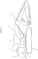
- FIG. 1 is a schematic side view of a hydraulic excavator 1 (construction machine) according to the present embodiment.
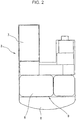
- FIG. 2 is a schematic plan view of an upper slewing body 3 of the hydraulic excavator 1 according to the present embodiment.
- the hydraulic excavator 1 according to the present embodiment includes a crawler-type lower traveling body 2 capable of self-traveling, an upper slewing body 3 slewably mounted on the lower traveling body 2, and a working device 4.
- the working device 4 is provided on the upper slewing body 3, for example, to excavate the soil.
- the upper slewing body 3 includes a slewing frame 5, as a vehicle body frame, slewably mounted on the lower traveling body 2.
- the hydraulic excavator 1 includes a counter weight 6 for balancing weight of the working device 4, a cab 7 occupied by an operator, a hood 8, and an engine housing 9.
- the engine housing 9 is provided in front of the counter weight 6 and is covered by the hood 8.
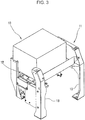
- the hydraulic excavator 1 also includes an engine (not shown) and an exhaust gas aftertreatment device 10 (see FIG. 3 ).
- the engine and exhaust gas aftertreatment device 10 are accommodated in the engine housing 9, and are supported by the slewing frame 5.
- the engine is, for example, a diesel engine.
- the exhaust gas aftertreatment device 10 including, for example, a urea-selective catalytic reduction (SCR) system, is connected to an exhaust system of the engine (not shown) to remove nitrogen oxides (NOx) etc. contained in the exhaust gas discharged from the diesel engine.
- SCR urea-selective catalytic reduction
- FIG. 3 is a perspective view of the aftertreatment device mount 11 in the hydraulic excavator 1 according to the present embodiment, in which the aftertreatment device mount 11 supports the exhaust gas aftertreatment device 10.
- the exhaust gas aftertreatment device 10 being supported by the aftertreatment device mount 11, is mounted on the slewing frame 5.
- the aftertreatment device mount 11 includes a mount top plate 12 (i.e., a top plate) and a plurality of legs 13 for horizontally supporting the mount top plate 12.
- the mount top plate 12 is connected to the exhaust gas aftertreatment device 10 by bolts or the like through a vibration absorbing member (connection member), such as mount rubber (not shown).
- connection member such as mount rubber
- the mount top plate 12 may be directly connected to the exhaust gas aftertreatment device 10 without intervening the connection member.
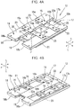
- FIG. 4A is a perspective top view of the mount top plate 12 according to the present embodiment
- FIG. 4B is a perspective bottom view of the mount top plate 12.
- FIG. 5 is an exploded perspective view of the mount top plate 12.
- the mount top plate 12 is formed in a substantially rectangular shape in plan view, as illustrated in FIGS. 4A and 4B , and includes a top plate body 14, a plurality of upper reinforcing members 15 (i.e., reinforcing members), a plurality of lower reinforcing members 16 (i.e., auxiliary reinforcing members), frame members (i.e., a first frame member 17 and a second frame member 18), and a groove closure member 19, as illustrated in FIG. 5 .
- upper reinforcing members 15 i.e., reinforcing members
- a plurality of lower reinforcing members 16 i.e., auxiliary reinforcing members
- frame members i.e., a first frame member 17 and a second frame member 18
- the top plate body 14 includes a pair of supports 20 (i.e., placement portions), a pair of outer walls 21, and a groove portion 22.
- Each of the pair of supports 20 includes a flat top surface (i.e., a placement surface).
- the exhaust gas aftertreatment device 10 is allowed to be placed on the top surface.
- the longitudinal direction L (i.e., first direction) of the mount top plate 12 and the lateral direction S (i.e., second direction) orthogonal to the longitudinal direction of the mount top plate 12 are indicated by the respective arrows.
- the pair of supports 20 extend parallel to each other in the longitudinal direction L.
- the pair of outer walls 21 are disposed on both lateral sides of the top plate body 14, each of the outer walls 21 extending vertically downward from the edge of the support 20 and extending parallel to each other in the longitudinal direction.
- the groove portion 22 is disposed between the pair of supports 20 and extends in the longitudinal direction. The groove portion 22 connects the pair of supports 20 to each other.
- the supports 20, the outer walls 21, and the groove portion 22 are all formed by bending a single top plate body 14.
- the pair of supports 20 are provided with a plurality of connecting portions 23 at predetermined positions in the longitudinal direction, at which the exhaust gas aftertreatment device 10 is connected.
- Each of the connecting portions 23 has a plurality of through-holes 24 into which fastening members such as bolts are inserted.
- the connecting portions 23 are indicated by broken lines in FIG. 5 .
- the groove portion 22 includes a pair of groove sidewalls 22a (inner walls) that are recessed downwardly from the supports 20 and extend vertically downward, and a flat groove bottom 22b (bottom) connecting the lower edges of the pair of groove sidewalls 22a.
- the groove bottom 22b is disposed at a position lower than the top surface (placement surface) of the support 20.
- the pair of groove sidewalls 22a vertically connect the pair of placement surfaces to the groove bottom 22b.
- the pair of outer walls 21 are connected to both lateral side edges of the pair of supports 20 and extend in the longitudinal direction.
- the pair of outer walls 21 are laterally opposed to the groove sidewalls 22a and, when the groove bottom 22b is assumed to be a reference surface, the support 20, the outer wall 21, and the groove sidewall 22a form an elongated convex shape.
- the groove sidewall 22a laterally separates a space below the support 20 from a space above the groove bottom 22b.
- the upper reinforcing members 15 are disposed to extend laterally at positions corresponding to the connecting portions 23 in the longitudinal direction, thereby reinforcing the pair of supports 20 and the groove portion 22. As illustrated in FIG. 4A , the upper reinforcing member 15 includes a pair of first reinforcing portions 15a that overlap with the top surfaces of the connecting portions 23 of the supports 20 and a pair of second reinforcing portions 15b that laterally connect the pair of first reinforcing portions 15a to each other and are fitted in the groove portion 22. Although the upper reinforcing member 15 is strip-shaped, generally extending in one direction (lateral direction), the pair of first reinforcing portions 15a are plates that extend in the horizontal direction and face in the vertical direction as illustrated in FIG.
- the pair of second reinforcing portions 15b are U-shaped vertical walls that face each other in the horizontal direction, whereby an opening P is formed between the pair of second reinforcing portions 15b.
- the opening P not only reduces the weight of the upper reinforcing member 15, but also facilitates bending of the second reinforcing portions 15b with respect to the first reinforcing portions 15a in manufacturing the upper reinforcing member 15.
- Both lateral side edges (see a side edge 15b2 of FIG. 6 ) of the pair of second reinforcing portions 15b abut on the groove sidewalls 22a.
- the opening may not be disposed between the pair of second reinforcing portions 15b.
- the first reinforcing portions 15a of the upper reinforcing member 15 attached to the top plate body 14 overlap with the connecting portions 23 of the supports 20, thereby increasing the substantial thickness of the connecting portions 23.
- the first reinforcing portions 15a are sandwiched between the top surface of the support 20 and the exhaust gas aftertreatment device 10 (or the connection member).
- the second reinforcing portion 15b fitted in the groove portion 22 reliably prevents the distortion of the groove portion 22. This causes the upper reinforcing member 15 to reinforce the top plate body 14, thereby increasing the rigidity of the top plate body 14.
- a gap H is formed between the groove bottom 22b and the lower edge of the second reinforcing portion 15b.
- the second reinforcing portion 15b includes a lower edge 15b1 (i.e., an abutment portion) abutting on the groove bottom 22b, a side edge 15b2 abutting on the groove sidewall 22a, and a cut-away portion 15b3 (i.e., a non-abutment portion) using a bending notch.
- the cut-away portion 15b3 is formed at the corner of the lower edge 15b1 and the side edge 15b2.
- the cut-away portion 15b3 is spaced apart from the groove bottom 22b and forms a gap H with the groove bottom 22b.
- the gap H allows liquid, such as water, to pass between the groove bottom 22b and the lower edge of the second reinforcing portion 15b.
- water entering the groove portion 22 is not blocked by the second reinforcing portion 15b and is easily drained, so that contamination and corrosion of the mount top plate 12 can be prevented.
- Water etc. that has passed through the gap H can be discharged, for example, from holes G of FIG. 5 .
- the first frame member 17 and the second frame member 18 may also be provided with cut-away portions using a bending notch described above, thus facilitating drainage.
- An open side at one end of the groove portion 22 of the top plate body 14 in the longitudinal direction is closed by part of the first frame member 17, and an open side at the other end is closed by the groove closure member 19.
- the groove closure member 19, which is attached to the groove portion 22, has the effect of suppressing undesirable distortion of the groove portion 22 and improves the rigidity of the top plate body 14 in conjunction with the upper reinforcing member 15.
- the lower reinforcing member 16 is secured to a surface, which is opposite to the placement surface, of the support 20 of the mount top plate 12 to laterally connect the outer wall 21 and the inner wall 22a of the groove portion 22.
- the lower reinforcing member 16 includes an abutment surface 16a abutting on the bottom surface (back surface) of the connecting portion 23 of the support 20 and a pair of vertical walls 16b contiguous with both ends (both ends in the longitudinal direction L) of the abutment surface 16a.
- the abutment surface 16a of the lower reinforcing member 16 overlaps with the connecting portion 23 of the support 20 from the back, the abutment surface 16a as well as the first reinforcing portion 15a increases the substantial thickness of the connecting portion 23.
- the lower reinforcing member 16 is disposed to overlap with the first reinforcing portion 15a of the reinforcing member 15 through the connecting portion 23, that is, to sandwich the connecting portion 23 between the lower reinforcing member 16 and the first reinforcing portion 15a of the reinforcing member 15.
- both ends of the pair of vertical walls 16b abut on the groove sidewall 22a and the outer wall 21. More preferably, both ends of the abutment surface 16a abut on the groove sidewall 22a and the outer wall 21.
- the first frame member 17 and the second frame member 18 are attached to longitudinal ends of the top plate body 14 as illustrated in FIG. 4B .
- the first frame member 17 includes a first base 17a, a first outer frame piece 17b erected from the outer edge of the first base 17a, and a pair of first inner frame pieces 17c erected from the inner edge of the first base 17a opposite to the first outer frame piece 17b.
- the first outer frame piece 17b and the pair of first inner frame pieces 17c extend laterally with respect to the top plate body 14.
- the second frame member 18 includes a second base 18a, a pair of second outer frame pieces 18b erected from the outer edge of the second base 18a, and a pair of second inner frame pieces 18c erected from the inner edge of the second base 18a opposite to the second outer frame pieces 18b.
- the pair of second inner frame pieces 18c and the pair of second outer frame pieces 18b extend laterally with respect to the top plate body 14.
- the first frame member 17 and the second frame member 18 are attached to both side edges, which intersect with the outer walls 21, of the top plate body 14, and thus the first frame member 17, the second frame member 18, and both outer walls 21 allow the mount top plate 12 to be a box structure with peripheral walls. That is, the first frame member 17 and the second frame member 18 close a space defined by the pair of supports 20 and the pair of outer walls 21 at both sides. Therefore, the rigidity of the mount top plate 12 increases without a significant increase in the weight of the mount top plate 12.
- the above structure allows the mount top plate 12 according to the present embodiment to be made lighter by using relatively thin plate material and to obtain sufficient rigidity.
- the aftertreatment device mount 11 can stably support the exhaust gas aftertreatment device 10 as illustrated in FIG. 3 .
- a number of the upper reinforcing members 15 (i.e. two) and a number of the lower reinforcing members 16 (i.e. four) are not limited to the above embodiment and one or more upper and lower reinforcing members may be disposed.
- the lower reinforcing members 16 may not be disposed.
- both the first frame member 17 and the second frame member 18 are not necessarily disposed, that is, either one of the first frame member 17 and the second frame member 18 may be disposed.
- the hydraulic excavator 1 including the crawler-type lower traveling body 2 is described as an exemplary construction machine.
- the present invention is not limited thereto and may be applied to, for example, a hydraulic excavator including a wheel-type lower traveling body.
- the present invention can be broadly applied to other construction machines such as a wheel loader, a dump truck, a hydraulic crane, etc.
- the construction machine includes a vehicle body frame for supporting an engine, an exhaust gas aftertreatment device connected to an exhaust system of the engine, and an aftertreatment device mount for supporting the exhaust gas aftertreatment device.
- the aftertreatment device mount includes a top plate.
- the top plate includes a pair of placement portions, a groove portion, a pair of outer walls, and at least one reinforcing member.
- the pair of placement portions extend in the first direction being horizontal, are spaced apart from each other in the second direction intersecting with the first direction and the vertical direction, and include placement surfaces on which the exhaust gas aftertreatment device is allowed to be placed.
- Each of the placement surfaces of the pair of placement portions is provided with a connecting portion connected to the exhaust gas aftertreatment device at one or more predetermined positions in the first direction.
- the groove portion is disposed between the pair of placement portions and connects the pair of placement portions to each other.
- the groove portion includes a bottom disposed at a position lower than the placement surface and a pair of inner walls connecting the pair of placement surfaces to the bottom.
- the pair of outer walls are connected to both side edges of the pair of placement portions in the second direction and extend in the first direction.
- the pair of outer walls are disposed to face the pair of inner walls in the second direction.
- the at least one reinforcing member is disposed to extend in the second direction at a position corresponding to the connecting portion in the first direction.
- the at least one reinforcing member includes a pair of first reinforcing portions that are disposed on the placement surfaces of the pair of placement portions and are sandwiched between the placement surfaces and the exhaust gas aftertreatment device; and at least one second reinforcing portion that is fitted in the groove portion and connects the pair of first reinforcing portions in the second direction.
- the top plate where a beam structure is formed by the placement portions, the outer walls, and the groove portion extending parallel to each other, has high strength in the direction in which the placement portions, the outer walls, and the groove portion extend. Furthermore, in the connecting portion connected to the exhaust gas aftertreatment device, the first reinforcing portions of the reinforcing member are sandwiched between the connecting portions and the exhaust gas aftertreatment device and the second reinforcing portion is fitted in the groove portion, which increases strength in a direction orthogonal to the direction in which the placement portions, the outer walls, and the groove portion extend.
- sufficient rigidity can be obtained even if the thickness dimension of the top plate is reduced, so that the thickness dimension of the top plate can be reduced, thereby facilitating weight reduction.
- the second reinforcing portion of the reinforcing member abuts on the bottom of the groove portion and the pair of inner walls.
- the construction machine further includes at least one auxiliary reinforcing member that is secured to a surface, which is opposite to the placement surface, of the placement portion and connects the outer wall and the inner wall of the groove portion in the second direction, the at least one auxiliary reinforcing member being disposed to sandwich the connecting portion between the at least one auxiliary reinforcing member and the first reinforcing portion of the reinforcing member.
- This structure using the reinforcing member disposed on the top surface of the connecting portion and the auxiliary reinforcing member disposed on the bottom surface of the connecting portion provides strength equivalent to a structure in which the thickness of the connecting portion is partially increased, thus increasing the rigidity.
- the construction machine still further includes at least one frame member that is attached to the side edge, which intersects with the outer walls, of the mount top plate and closes a space defined by the outer walls and the placement portions at a side or sides.
- This provides a box-structured top plate with the outer walls and the at least one frame member, and high rigidity can be obtained while reducing the weight of the top plate.
- the second reinforcing portion of the reinforcing member includes an abutment portion abutting on the bottom and a non-abutment portion that is spaced apart from the bottom and forms a gap with the bottom. This prevents water from being blocked by the second reinforcing portion even if water enters the groove portion, and water is easily drained through the gap between the bottom of the groove portion and the second reinforcing portion.
- a mount top plate of the aftertreatment device mount includes a support on which the exhaust gas aftertreatment device is placed, a pair of outer walls extending parallel, a groove portion parallel to the outer walls, a connecting portion provided on the support, and an upper reinforcing member orthogonal to the groove portion at a position of the connecting portion.
- the upper reinforcing member includes a first reinforcing portion for reinforcing the connecting portion and a second reinforcing portion to be fitted in the groove portion.
Landscapes
- Engineering & Computer Science (AREA)
- Chemical & Material Sciences (AREA)
- General Engineering & Computer Science (AREA)
- Combustion & Propulsion (AREA)
- Mechanical Engineering (AREA)
- Civil Engineering (AREA)
- Mining & Mineral Resources (AREA)
- Structural Engineering (AREA)
- Transportation (AREA)
- Toxicology (AREA)
- Chemical Kinetics & Catalysis (AREA)
- Health & Medical Sciences (AREA)
- Exhaust Gas After Treatment (AREA)
- Component Parts Of Construction Machinery (AREA)
- Cooling, Air Intake And Gas Exhaust, And Fuel Tank Arrangements In Propulsion Units (AREA)
Claims (5)
- Baumaschine mit:einem Fahrzeugkörperrahmen (5) zum Stützen eines Verbrennungsmotors;einer Abgasnachbehandlungsvorrichtung (10), die mit einem Abgassystem des Verbrennungsmotors verbunden ist; undeiner Nachbehandlungsvorrichtungshalterung (11) zum Stützen der Abgasnachbehandlungsvorrichtung,wobei die Nachbehandlungsvorrichtungshalterung eine obere Platte (12) aufweist,dadurch gekennzeichnet, dassdie obere Platte Folgendes aufweist:ein Paar an Anordnungsabschnitten (20), die sich in einer ersten Richtung erstrecken, die horizontal ist, voneinander in einer zweiten Richtung beabstandet sind, die sich mit der ersten Richtung und einer vertikalen Richtung schneidet, und die Anordnungsflächen haben, auf denen die Abgasnachbehandlungsvorrichtung angeordnet werden kann, wobei jede der Anordnungsflächen des Paares an Anordnungsabschnitten mit einem Verbindungsabschnitt versehen ist, der mit der Abgasnachbehandlungsvorrichtung an einer oder an mehreren vorbestimmten Positionen in der ersten Richtung verbunden ist;einen Nutabschnitt (22), der zwischen dem Paar an Anordnungsabschnitten angeordnet ist, und das Paar der Anordnungsabschnitte miteinander verbindet, wobei der Nutabschnitt einen Boden, der an einer Position angeordnet ist, die niedriger als die Anordnungsfläche ist, und ein Paar an Innenwänden hat, die das Paar der Anordnungsflächen mit dem Boden verbinden;ein Paar an Außenwänden (21), die mit beiden Seitenrändern des Paares an Bodenabschnitten in der zweiten Richtung verbunden sind und sich in der ersten Richtung erstrecken, wobei die als Paar vorgesehenen Außenwände so angeordnet sind, dass sie dem Paar der Innenwände in der zweiten Richtung zugewandt sind; undzumindest ein Verstärkungselement (15), das so angeordnet ist, dass es sich in der zweiten Richtung an einer Position erstreckt, die dem Verbindungsabschnitt in der ersten Richtung entspricht, unddas zumindest eine Verstärkungselement ein Paar an ersten Verstärkungsabschnitten (15a), die an den Anordnungsflächen des Paares der Anordnungsabschnitte angeordnet sind und sandwichartig zwischen den Anordnungsflächen und der Abgasnachbehandlungsvorrichtung angeordnet sind, und zumindest einen zweiten Verstärkungsabschnitt (15b) hat, der in dem Nutabschnitt sitzt und das Paar der ersten Verstärkungsabschnitte in der zweiten Richtung verbindet.
- Baumaschine gemäß Anspruch 1, wobeider zumindest eine zweite Verstärkungsabschnitt des zumindest einen Verstärkungselementes an dem Boden des Nutabschnittes und dem Paar der Innenwände anliegt.
- Baumaschine gemäß Anspruch 1 oder 2, die des Weiteren Folgendes aufweist:zumindest ein Hilfsverstärkungselement (16), das an einer der Anordnungsfläche gegenüberliegenden Fläche des Anordnungsabschnittes gesichert ist, und das die Außenwand und die Innenwand des Nutabschnittes in der zweiten Richtung verbindet, wobei das zumindest eine Hilfsverstärkungselement so angeordnet ist, dass es den Verbindungsabschnitt zwischen dem zumindest einen Hilfsverstärkungselement und dem ersten Verstärkungsabschnitt des zumindest einen Verstärkungselementes sandwichartig anordnet.
- Baumaschine gemäß einem der Ansprüche 1 bis 3, die des Weiteren Folgendes aufweist:zumindest ein Rahmenelement (17, 18), das an einem mit den Außenwänden verbundenen Seitenrand der oberen Platte angebracht ist und einen Raum, der durch die Außenwände und die Anordnungsabschnitte definiert ist, an einer Seite schließt.
- Baumaschine gemäß einem der Ansprüche 1 bis 4, wobeider zumindest eine zweite Verstärkungsabschnitt des zumindest einen Verstärkungselementes einen Anlageabschnitt (15b1), der an dem Boden anliegt, und einen Nichtanlageabschnitt (15b3) hat, der von dem Boden beabstandet ist und einen Zwischenraum zu dem Boden ausbildet.
Applications Claiming Priority (1)
| Application Number | Priority Date | Filing Date | Title |
|---|---|---|---|
| JP2016173562A JP6376191B2 (ja) | 2016-09-06 | 2016-09-06 | 建設機械 |
Publications (2)
| Publication Number | Publication Date |
|---|---|
| EP3290594A1 EP3290594A1 (de) | 2018-03-07 |
| EP3290594B1 true EP3290594B1 (de) | 2019-02-20 |
Family
ID=59699577
Family Applications (1)
| Application Number | Title | Priority Date | Filing Date |
|---|---|---|---|
| EP17187652.7A Active EP3290594B1 (de) | 2016-09-06 | 2017-08-24 | Baumaschine |
Country Status (4)
| Country | Link |
|---|---|
| US (1) | US9976468B2 (de) |
| EP (1) | EP3290594B1 (de) |
| JP (1) | JP6376191B2 (de) |
| CN (1) | CN107794964B (de) |
Families Citing this family (2)
| Publication number | Priority date | Publication date | Assignee | Title |
|---|---|---|---|---|
| CN109026309B (zh) * | 2018-08-03 | 2019-12-31 | 广东裕田霸力科技股份有限公司 | 一种用于汽车消声器的减排消声阀门 |
| US10934907B2 (en) | 2019-03-20 | 2021-03-02 | Caterpillar Inc. | Outlet for exhaust gas aftertreatment module |
Family Cites Families (12)
| Publication number | Priority date | Publication date | Assignee | Title |
|---|---|---|---|---|
| US8420019B2 (en) | 2008-07-10 | 2013-04-16 | Hitachi Construction Machinery Co., Ltd. | Exhaust gas treatment apparatus |
| US8191668B2 (en) * | 2008-08-07 | 2012-06-05 | Caterpillar Inc. | Mounting assembly for emissions control system |
| JP4897757B2 (ja) * | 2008-09-09 | 2012-03-14 | 日立建機株式会社 | 排気ガス処理装置 |
| JP2011105065A (ja) * | 2009-11-13 | 2011-06-02 | Hitachi Constr Mach Co Ltd | 建設機械 |
| JP2013224542A (ja) * | 2012-04-20 | 2013-10-31 | Kobelco Contstruction Machinery Ltd | 作業機械 |
| US9316136B2 (en) | 2012-07-05 | 2016-04-19 | Komatsu Ltd. | Engine unit and work vehicle |
| JP5840098B2 (ja) * | 2012-09-26 | 2016-01-06 | 株式会社クボタ | 作業車の排気処理装置接続構造 |
| JP2014121975A (ja) * | 2012-12-21 | 2014-07-03 | Hitachi Constr Mach Co Ltd | 浄化装置を備えた建設機械 |
| JP6066844B2 (ja) * | 2013-06-21 | 2017-01-25 | Jfe建材株式会社 | デッキ下地屋根の設備設置用基礎およびその施工方法 |
| JP5989017B2 (ja) | 2014-01-30 | 2016-09-07 | 日立建機株式会社 | 建設機械 |
| JP2015190317A (ja) * | 2014-03-27 | 2015-11-02 | ヤンマー株式会社 | エンジン装置 |
| CN203974535U (zh) * | 2014-06-11 | 2014-12-03 | 北汽福田汽车股份有限公司 | 排气系统悬挂支架、排气系统悬挂装置及车辆 |
-
2016
- 2016-09-06 JP JP2016173562A patent/JP6376191B2/ja active Active
-
2017
- 2017-08-16 US US15/678,151 patent/US9976468B2/en active Active
- 2017-08-24 EP EP17187652.7A patent/EP3290594B1/de active Active
- 2017-09-06 CN CN201710800347.8A patent/CN107794964B/zh active Active
Non-Patent Citations (1)
| Title |
|---|
| None * |
Also Published As
| Publication number | Publication date |
|---|---|
| CN107794964A (zh) | 2018-03-13 |
| JP6376191B2 (ja) | 2018-08-22 |
| EP3290594A1 (de) | 2018-03-07 |
| JP2018040122A (ja) | 2018-03-15 |
| US20180066564A1 (en) | 2018-03-08 |
| US9976468B2 (en) | 2018-05-22 |
| CN107794964B (zh) | 2021-07-30 |
Similar Documents
| Publication | Publication Date | Title |
|---|---|---|
| US9333992B2 (en) | Upper slewing body for use in construction machine | |
| US8857384B2 (en) | Construction machine | |
| EP2565331B1 (de) | Geräteunterstützendes Element und oberer Schwenkkörper damit | |
| JP5582167B2 (ja) | 建設機械 | |
| US9745717B2 (en) | Construction machine | |
| EP3290594B1 (de) | Baumaschine | |
| EP2757201B1 (de) | Frontbügel für Arbeitsmaschine | |
| EP2886725B1 (de) | Baumaschine | |
| EP2642032A1 (de) | Pendelrahmen für eine baumaschine | |
| JP5654856B2 (ja) | 油圧ショベル | |
| JP2013224542A (ja) | 作業機械 | |
| US9243383B2 (en) | Working machine | |
| EP3798369B1 (de) | Baumaschine | |
| US9670647B2 (en) | Work vehicle | |
| JP5799722B2 (ja) | 作業機械 | |
| JP5018746B2 (ja) | 作業機械のタンクの取り付け構造 | |
| KR20060053960A (ko) | 건설 기계의 선회 프레임 구조 | |
| JP5692248B2 (ja) | 作業機械 | |
| JP6079689B2 (ja) | 作業機械 | |
| JP5929236B2 (ja) | 作業機械 | |
| JP2015121020A (ja) | 建設機械 | |
| JP2013167097A (ja) | 建設機械 | |
| JP2008201189A (ja) | 作業機械における燃料タンク構造 | |
| JP2018165125A (ja) | 建設機械用の燃料タンク及びショベル |
Legal Events
| Date | Code | Title | Description |
|---|---|---|---|
| PUAI | Public reference made under article 153(3) epc to a published international application that has entered the european phase |
Free format text: ORIGINAL CODE: 0009012 |
|
| STAA | Information on the status of an ep patent application or granted ep patent |
Free format text: STATUS: THE APPLICATION HAS BEEN PUBLISHED |
|
| AK | Designated contracting states |
Kind code of ref document: A1 Designated state(s): AL AT BE BG CH CY CZ DE DK EE ES FI FR GB GR HR HU IE IS IT LI LT LU LV MC MK MT NL NO PL PT RO RS SE SI SK SM TR |
|
| AX | Request for extension of the european patent |
Extension state: BA ME |
|
| STAA | Information on the status of an ep patent application or granted ep patent |
Free format text: STATUS: REQUEST FOR EXAMINATION WAS MADE |
|
| 17P | Request for examination filed |
Effective date: 20180621 |
|
| RBV | Designated contracting states (corrected) |
Designated state(s): AL AT BE BG CH CY CZ DE DK EE ES FI FR GB GR HR HU IE IS IT LI LT LU LV MC MK MT NL NO PL PT RO RS SE SI SK SM TR |
|
| GRAP | Despatch of communication of intention to grant a patent |
Free format text: ORIGINAL CODE: EPIDOSNIGR1 |
|
| STAA | Information on the status of an ep patent application or granted ep patent |
Free format text: STATUS: GRANT OF PATENT IS INTENDED |
|
| RIC1 | Information provided on ipc code assigned before grant |
Ipc: B60K 13/04 20060101ALI20180809BHEP Ipc: F01N 13/18 20100101ALI20180809BHEP Ipc: E02F 9/08 20060101AFI20180809BHEP |
|
| INTG | Intention to grant announced |
Effective date: 20180831 |
|
| GRAS | Grant fee paid |
Free format text: ORIGINAL CODE: EPIDOSNIGR3 |
|
| GRAA | (expected) grant |
Free format text: ORIGINAL CODE: 0009210 |
|
| STAA | Information on the status of an ep patent application or granted ep patent |
Free format text: STATUS: THE PATENT HAS BEEN GRANTED |
|
| AK | Designated contracting states |
Kind code of ref document: B1 Designated state(s): AL AT BE BG CH CY CZ DE DK EE ES FI FR GB GR HR HU IE IS IT LI LT LU LV MC MK MT NL NO PL PT RO RS SE SI SK SM TR |
|
| REG | Reference to a national code |
Ref country code: GB Ref legal event code: FG4D |
|
| REG | Reference to a national code |
Ref country code: CH Ref legal event code: EP |
|
| REG | Reference to a national code |
Ref country code: DE Ref legal event code: R096 Ref document number: 602017002221 Country of ref document: DE |
|
| REG | Reference to a national code |
Ref country code: AT Ref legal event code: REF Ref document number: 1098349 Country of ref document: AT Kind code of ref document: T Effective date: 20190315 |
|
| REG | Reference to a national code |
Ref country code: IE Ref legal event code: FG4D |
|
| REG | Reference to a national code |
Ref country code: LT Ref legal event code: MG4D Ref country code: NL Ref legal event code: MP Effective date: 20190220 |
|
| PG25 | Lapsed in a contracting state [announced via postgrant information from national office to epo] |
Ref country code: SE Free format text: LAPSE BECAUSE OF FAILURE TO SUBMIT A TRANSLATION OF THE DESCRIPTION OR TO PAY THE FEE WITHIN THE PRESCRIBED TIME-LIMIT Effective date: 20190220 Ref country code: FI Free format text: LAPSE BECAUSE OF FAILURE TO SUBMIT A TRANSLATION OF THE DESCRIPTION OR TO PAY THE FEE WITHIN THE PRESCRIBED TIME-LIMIT Effective date: 20190220 Ref country code: LT Free format text: LAPSE BECAUSE OF FAILURE TO SUBMIT A TRANSLATION OF THE DESCRIPTION OR TO PAY THE FEE WITHIN THE PRESCRIBED TIME-LIMIT Effective date: 20190220 Ref country code: NO Free format text: LAPSE BECAUSE OF FAILURE TO SUBMIT A TRANSLATION OF THE DESCRIPTION OR TO PAY THE FEE WITHIN THE PRESCRIBED TIME-LIMIT Effective date: 20190520 Ref country code: PT Free format text: LAPSE BECAUSE OF FAILURE TO SUBMIT A TRANSLATION OF THE DESCRIPTION OR TO PAY THE FEE WITHIN THE PRESCRIBED TIME-LIMIT Effective date: 20190620 |
|
| PG25 | Lapsed in a contracting state [announced via postgrant information from national office to epo] |
Ref country code: BG Free format text: LAPSE BECAUSE OF FAILURE TO SUBMIT A TRANSLATION OF THE DESCRIPTION OR TO PAY THE FEE WITHIN THE PRESCRIBED TIME-LIMIT Effective date: 20190520 Ref country code: GR Free format text: LAPSE BECAUSE OF FAILURE TO SUBMIT A TRANSLATION OF THE DESCRIPTION OR TO PAY THE FEE WITHIN THE PRESCRIBED TIME-LIMIT Effective date: 20190521 Ref country code: IS Free format text: LAPSE BECAUSE OF FAILURE TO SUBMIT A TRANSLATION OF THE DESCRIPTION OR TO PAY THE FEE WITHIN THE PRESCRIBED TIME-LIMIT Effective date: 20190620 Ref country code: LV Free format text: LAPSE BECAUSE OF FAILURE TO SUBMIT A TRANSLATION OF THE DESCRIPTION OR TO PAY THE FEE WITHIN THE PRESCRIBED TIME-LIMIT Effective date: 20190220 Ref country code: NL Free format text: LAPSE BECAUSE OF FAILURE TO SUBMIT A TRANSLATION OF THE DESCRIPTION OR TO PAY THE FEE WITHIN THE PRESCRIBED TIME-LIMIT Effective date: 20190220 Ref country code: HR Free format text: LAPSE BECAUSE OF FAILURE TO SUBMIT A TRANSLATION OF THE DESCRIPTION OR TO PAY THE FEE WITHIN THE PRESCRIBED TIME-LIMIT Effective date: 20190220 Ref country code: RS Free format text: LAPSE BECAUSE OF FAILURE TO SUBMIT A TRANSLATION OF THE DESCRIPTION OR TO PAY THE FEE WITHIN THE PRESCRIBED TIME-LIMIT Effective date: 20190220 |
|
| REG | Reference to a national code |
Ref country code: AT Ref legal event code: MK05 Ref document number: 1098349 Country of ref document: AT Kind code of ref document: T Effective date: 20190220 |
|
| PG25 | Lapsed in a contracting state [announced via postgrant information from national office to epo] |
Ref country code: CZ Free format text: LAPSE BECAUSE OF FAILURE TO SUBMIT A TRANSLATION OF THE DESCRIPTION OR TO PAY THE FEE WITHIN THE PRESCRIBED TIME-LIMIT Effective date: 20190220 Ref country code: AL Free format text: LAPSE BECAUSE OF FAILURE TO SUBMIT A TRANSLATION OF THE DESCRIPTION OR TO PAY THE FEE WITHIN THE PRESCRIBED TIME-LIMIT Effective date: 20190220 Ref country code: RO Free format text: LAPSE BECAUSE OF FAILURE TO SUBMIT A TRANSLATION OF THE DESCRIPTION OR TO PAY THE FEE WITHIN THE PRESCRIBED TIME-LIMIT Effective date: 20190220 Ref country code: ES Free format text: LAPSE BECAUSE OF FAILURE TO SUBMIT A TRANSLATION OF THE DESCRIPTION OR TO PAY THE FEE WITHIN THE PRESCRIBED TIME-LIMIT Effective date: 20190220 Ref country code: EE Free format text: LAPSE BECAUSE OF FAILURE TO SUBMIT A TRANSLATION OF THE DESCRIPTION OR TO PAY THE FEE WITHIN THE PRESCRIBED TIME-LIMIT Effective date: 20190220 Ref country code: SK Free format text: LAPSE BECAUSE OF FAILURE TO SUBMIT A TRANSLATION OF THE DESCRIPTION OR TO PAY THE FEE WITHIN THE PRESCRIBED TIME-LIMIT Effective date: 20190220 Ref country code: DK Free format text: LAPSE BECAUSE OF FAILURE TO SUBMIT A TRANSLATION OF THE DESCRIPTION OR TO PAY THE FEE WITHIN THE PRESCRIBED TIME-LIMIT Effective date: 20190220 |
|
| REG | Reference to a national code |
Ref country code: DE Ref legal event code: R097 Ref document number: 602017002221 Country of ref document: DE |
|
| PG25 | Lapsed in a contracting state [announced via postgrant information from national office to epo] |
Ref country code: PL Free format text: LAPSE BECAUSE OF FAILURE TO SUBMIT A TRANSLATION OF THE DESCRIPTION OR TO PAY THE FEE WITHIN THE PRESCRIBED TIME-LIMIT Effective date: 20190220 Ref country code: SM Free format text: LAPSE BECAUSE OF FAILURE TO SUBMIT A TRANSLATION OF THE DESCRIPTION OR TO PAY THE FEE WITHIN THE PRESCRIBED TIME-LIMIT Effective date: 20190220 |
|
| PLBE | No opposition filed within time limit |
Free format text: ORIGINAL CODE: 0009261 |
|
| STAA | Information on the status of an ep patent application or granted ep patent |
Free format text: STATUS: NO OPPOSITION FILED WITHIN TIME LIMIT |
|
| PG25 | Lapsed in a contracting state [announced via postgrant information from national office to epo] |
Ref country code: AT Free format text: LAPSE BECAUSE OF FAILURE TO SUBMIT A TRANSLATION OF THE DESCRIPTION OR TO PAY THE FEE WITHIN THE PRESCRIBED TIME-LIMIT Effective date: 20190220 |
|
| 26N | No opposition filed |
Effective date: 20191121 |
|
| PG25 | Lapsed in a contracting state [announced via postgrant information from national office to epo] |
Ref country code: SI Free format text: LAPSE BECAUSE OF FAILURE TO SUBMIT A TRANSLATION OF THE DESCRIPTION OR TO PAY THE FEE WITHIN THE PRESCRIBED TIME-LIMIT Effective date: 20190220 |
|
| PG25 | Lapsed in a contracting state [announced via postgrant information from national office to epo] |
Ref country code: TR Free format text: LAPSE BECAUSE OF FAILURE TO SUBMIT A TRANSLATION OF THE DESCRIPTION OR TO PAY THE FEE WITHIN THE PRESCRIBED TIME-LIMIT Effective date: 20190220 |
|
| PG25 | Lapsed in a contracting state [announced via postgrant information from national office to epo] |
Ref country code: LU Free format text: LAPSE BECAUSE OF NON-PAYMENT OF DUE FEES Effective date: 20190824 Ref country code: MC Free format text: LAPSE BECAUSE OF FAILURE TO SUBMIT A TRANSLATION OF THE DESCRIPTION OR TO PAY THE FEE WITHIN THE PRESCRIBED TIME-LIMIT Effective date: 20190220 |
|
| REG | Reference to a national code |
Ref country code: BE Ref legal event code: MM Effective date: 20190831 |
|
| PG25 | Lapsed in a contracting state [announced via postgrant information from national office to epo] |
Ref country code: IE Free format text: LAPSE BECAUSE OF NON-PAYMENT OF DUE FEES Effective date: 20190824 |
|
| PG25 | Lapsed in a contracting state [announced via postgrant information from national office to epo] |
Ref country code: BE Free format text: LAPSE BECAUSE OF NON-PAYMENT OF DUE FEES Effective date: 20190831 |
|
| REG | Reference to a national code |
Ref country code: CH Ref legal event code: PL |
|
| PG25 | Lapsed in a contracting state [announced via postgrant information from national office to epo] |
Ref country code: CH Free format text: LAPSE BECAUSE OF NON-PAYMENT OF DUE FEES Effective date: 20200831 Ref country code: LI Free format text: LAPSE BECAUSE OF NON-PAYMENT OF DUE FEES Effective date: 20200831 |
|
| PG25 | Lapsed in a contracting state [announced via postgrant information from national office to epo] |
Ref country code: CY Free format text: LAPSE BECAUSE OF FAILURE TO SUBMIT A TRANSLATION OF THE DESCRIPTION OR TO PAY THE FEE WITHIN THE PRESCRIBED TIME-LIMIT Effective date: 20190220 |
|
| PG25 | Lapsed in a contracting state [announced via postgrant information from national office to epo] |
Ref country code: MT Free format text: LAPSE BECAUSE OF FAILURE TO SUBMIT A TRANSLATION OF THE DESCRIPTION OR TO PAY THE FEE WITHIN THE PRESCRIBED TIME-LIMIT Effective date: 20190220 Ref country code: HU Free format text: LAPSE BECAUSE OF FAILURE TO SUBMIT A TRANSLATION OF THE DESCRIPTION OR TO PAY THE FEE WITHIN THE PRESCRIBED TIME-LIMIT; INVALID AB INITIO Effective date: 20170824 |
|
| PG25 | Lapsed in a contracting state [announced via postgrant information from national office to epo] |
Ref country code: MK Free format text: LAPSE BECAUSE OF FAILURE TO SUBMIT A TRANSLATION OF THE DESCRIPTION OR TO PAY THE FEE WITHIN THE PRESCRIBED TIME-LIMIT Effective date: 20190220 |
|
| PGFP | Annual fee paid to national office [announced via postgrant information from national office to epo] |
Ref country code: IT Payment date: 20230711 Year of fee payment: 7 |
|
| PGFP | Annual fee paid to national office [announced via postgrant information from national office to epo] |
Ref country code: DE Payment date: 20240702 Year of fee payment: 8 |
|
| PGFP | Annual fee paid to national office [announced via postgrant information from national office to epo] |
Ref country code: GB Payment date: 20240701 Year of fee payment: 8 |
|
| PGFP | Annual fee paid to national office [announced via postgrant information from national office to epo] |
Ref country code: FR Payment date: 20240702 Year of fee payment: 8 |
|
| PG25 | Lapsed in a contracting state [announced via postgrant information from national office to epo] |
Ref country code: IT Free format text: LAPSE BECAUSE OF NON-PAYMENT OF DUE FEES Effective date: 20240824 |
|
| REG | Reference to a national code |
Ref country code: DE Ref legal event code: R119 Ref document number: 602017002221 Country of ref document: DE |