EP3282954B1 - Pince à positionnement commandé magnétiquement - Google Patents
Pince à positionnement commandé magnétiquement Download PDFInfo
- Publication number
- EP3282954B1 EP3282954B1 EP16780691.8A EP16780691A EP3282954B1 EP 3282954 B1 EP3282954 B1 EP 3282954B1 EP 16780691 A EP16780691 A EP 16780691A EP 3282954 B1 EP3282954 B1 EP 3282954B1
- Authority
- EP
- European Patent Office
- Prior art keywords
- grasper
- control element
- jaw
- magnetic
- variations
- Prior art date
- Legal status (The legal status is an assumption and is not a legal conclusion. Google has not performed a legal analysis and makes no representation as to the accuracy of the status listed.)
- Active
Links
- 230000005291 magnetic effect Effects 0.000 claims description 355
- 239000003302 ferromagnetic material Substances 0.000 claims description 24
- 239000002889 diamagnetic material Substances 0.000 claims description 16
- 239000004033 plastic Substances 0.000 claims description 15
- 229920003023 plastic Polymers 0.000 claims description 15
- 239000010935 stainless steel Substances 0.000 claims description 8
- 229910001220 stainless steel Inorganic materials 0.000 claims description 8
- 239000012811 non-conductive material Substances 0.000 claims description 7
- 238000012800 visualization Methods 0.000 description 123
- 230000008878 coupling Effects 0.000 description 79
- 238000010168 coupling process Methods 0.000 description 79
- 238000005859 coupling reaction Methods 0.000 description 79
- 239000000463 material Substances 0.000 description 63
- 239000000696 magnetic material Substances 0.000 description 47
- 230000033001 locomotion Effects 0.000 description 25
- 238000000034 method Methods 0.000 description 25
- 230000007246 mechanism Effects 0.000 description 19
- 238000000576 coating method Methods 0.000 description 15
- 238000007373 indentation Methods 0.000 description 15
- 238000001356 surgical procedure Methods 0.000 description 15
- 239000002902 ferrimagnetic material Substances 0.000 description 10
- 230000008859 change Effects 0.000 description 9
- 230000007423 decrease Effects 0.000 description 9
- 238000002324 minimally invasive surgery Methods 0.000 description 9
- 230000005294 ferromagnetic effect Effects 0.000 description 8
- 239000011248 coating agent Substances 0.000 description 5
- XEEYBQQBJWHFJM-UHFFFAOYSA-N Iron Chemical compound [Fe] XEEYBQQBJWHFJM-UHFFFAOYSA-N 0.000 description 4
- PXHVJJICTQNCMI-UHFFFAOYSA-N Nickel Chemical compound [Ni] PXHVJJICTQNCMI-UHFFFAOYSA-N 0.000 description 4
- 210000003815 abdominal wall Anatomy 0.000 description 4
- 230000000694 effects Effects 0.000 description 4
- 230000005293 ferrimagnetic effect Effects 0.000 description 4
- 239000004020 conductor Substances 0.000 description 3
- 210000000232 gallbladder Anatomy 0.000 description 3
- 230000005484 gravity Effects 0.000 description 3
- 210000000056 organ Anatomy 0.000 description 3
- 239000000725 suspension Substances 0.000 description 3
- RYGMFSIKBFXOCR-UHFFFAOYSA-N Copper Chemical compound [Cu] RYGMFSIKBFXOCR-UHFFFAOYSA-N 0.000 description 2
- RTAQQCXQSZGOHL-UHFFFAOYSA-N Titanium Chemical compound [Ti] RTAQQCXQSZGOHL-UHFFFAOYSA-N 0.000 description 2
- HCHKCACWOHOZIP-UHFFFAOYSA-N Zinc Chemical compound [Zn] HCHKCACWOHOZIP-UHFFFAOYSA-N 0.000 description 2
- 210000001015 abdomen Anatomy 0.000 description 2
- 210000000683 abdominal cavity Anatomy 0.000 description 2
- 238000013459 approach Methods 0.000 description 2
- 229910017052 cobalt Inorganic materials 0.000 description 2
- 239000010941 cobalt Substances 0.000 description 2
- GUTLYIVDDKVIGB-UHFFFAOYSA-N cobalt atom Chemical compound [Co] GUTLYIVDDKVIGB-UHFFFAOYSA-N 0.000 description 2
- 210000001072 colon Anatomy 0.000 description 2
- 229910052802 copper Inorganic materials 0.000 description 2
- 239000010949 copper Substances 0.000 description 2
- 230000003247 decreasing effect Effects 0.000 description 2
- -1 for example Substances 0.000 description 2
- 229910052742 iron Inorganic materials 0.000 description 2
- 239000011133 lead Substances 0.000 description 2
- 229910052759 nickel Inorganic materials 0.000 description 2
- 229920001778 nylon Polymers 0.000 description 2
- 239000003973 paint Substances 0.000 description 2
- 239000002907 paramagnetic material Substances 0.000 description 2
- 229920002725 thermoplastic elastomer Polymers 0.000 description 2
- 239000010936 titanium Substances 0.000 description 2
- 229910052719 titanium Inorganic materials 0.000 description 2
- 230000007704 transition Effects 0.000 description 2
- 229910052725 zinc Inorganic materials 0.000 description 2
- 239000011701 zinc Substances 0.000 description 2
- 229910000684 Cobalt-chrome Inorganic materials 0.000 description 1
- JOYRKODLDBILNP-UHFFFAOYSA-N Ethyl urethane Chemical compound CCOC(N)=O JOYRKODLDBILNP-UHFFFAOYSA-N 0.000 description 1
- 239000004677 Nylon Substances 0.000 description 1
- 239000004696 Poly ether ether ketone Substances 0.000 description 1
- 239000004698 Polyethylene Substances 0.000 description 1
- 239000004642 Polyimide Substances 0.000 description 1
- QJVKUMXDEUEQLH-UHFFFAOYSA-N [B].[Fe].[Nd] Chemical compound [B].[Fe].[Nd] QJVKUMXDEUEQLH-UHFFFAOYSA-N 0.000 description 1
- WAIPAZQMEIHHTJ-UHFFFAOYSA-N [Cr].[Co] Chemical compound [Cr].[Co] WAIPAZQMEIHHTJ-UHFFFAOYSA-N 0.000 description 1
- 230000003187 abdominal effect Effects 0.000 description 1
- 229920000122 acrylonitrile butadiene styrene Polymers 0.000 description 1
- 239000004676 acrylonitrile butadiene styrene Substances 0.000 description 1
- 229910045601 alloy Inorganic materials 0.000 description 1
- 239000000956 alloy Substances 0.000 description 1
- 229910000828 alnico Inorganic materials 0.000 description 1
- 238000000418 atomic force spectrum Methods 0.000 description 1
- 230000004323 axial length Effects 0.000 description 1
- 238000007681 bariatric surgery Methods 0.000 description 1
- 230000009286 beneficial effect Effects 0.000 description 1
- JUPQTSLXMOCDHR-UHFFFAOYSA-N benzene-1,4-diol;bis(4-fluorophenyl)methanone Chemical compound OC1=CC=C(O)C=C1.C1=CC(F)=CC=C1C(=O)C1=CC=C(F)C=C1 JUPQTSLXMOCDHR-UHFFFAOYSA-N 0.000 description 1
- 230000015572 biosynthetic process Effects 0.000 description 1
- 230000000903 blocking effect Effects 0.000 description 1
- 239000000919 ceramic Substances 0.000 description 1
- KPLQYGBQNPPQGA-UHFFFAOYSA-N cobalt samarium Chemical compound [Co].[Sm] KPLQYGBQNPPQGA-UHFFFAOYSA-N 0.000 description 1
- 239000010952 cobalt-chrome Substances 0.000 description 1
- 230000001934 delay Effects 0.000 description 1
- 230000001419 dependent effect Effects 0.000 description 1
- 230000003292 diminished effect Effects 0.000 description 1
- 239000004811 fluoropolymer Substances 0.000 description 1
- 229920002313 fluoropolymer Polymers 0.000 description 1
- 238000003384 imaging method Methods 0.000 description 1
- 238000002357 laparoscopic surgery Methods 0.000 description 1
- 229910052751 metal Inorganic materials 0.000 description 1
- 239000002184 metal Substances 0.000 description 1
- 150000002739 metals Chemical class 0.000 description 1
- 239000000203 mixture Substances 0.000 description 1
- 238000012986 modification Methods 0.000 description 1
- 230000004048 modification Effects 0.000 description 1
- 229910001172 neodymium magnet Inorganic materials 0.000 description 1
- 238000002355 open surgical procedure Methods 0.000 description 1
- 239000004417 polycarbonate Substances 0.000 description 1
- 229920000515 polycarbonate Polymers 0.000 description 1
- 229920002530 polyetherether ketone Polymers 0.000 description 1
- 229920000573 polyethylene Polymers 0.000 description 1
- 229920001721 polyimide Polymers 0.000 description 1
- 229920001296 polysiloxane Polymers 0.000 description 1
- 238000011084 recovery Methods 0.000 description 1
- 230000001846 repelling effect Effects 0.000 description 1
- 230000004044 response Effects 0.000 description 1
- 229910000938 samarium–cobalt magnet Inorganic materials 0.000 description 1
- 230000000451 tissue damage Effects 0.000 description 1
- 231100000827 tissue damage Toxicity 0.000 description 1
- 229910000859 α-Fe Inorganic materials 0.000 description 1
Images


Classifications
-
- A—HUMAN NECESSITIES
- A61—MEDICAL OR VETERINARY SCIENCE; HYGIENE
- A61B—DIAGNOSIS; SURGERY; IDENTIFICATION
- A61B34/00—Computer-aided surgery; Manipulators or robots specially adapted for use in surgery
- A61B34/70—Manipulators specially adapted for use in surgery
- A61B34/73—Manipulators for magnetic surgery
-
- A—HUMAN NECESSITIES
- A61—MEDICAL OR VETERINARY SCIENCE; HYGIENE
- A61B—DIAGNOSIS; SURGERY; IDENTIFICATION
- A61B17/00—Surgical instruments, devices or methods, e.g. tourniquets
- A61B17/28—Surgical forceps
- A61B17/29—Forceps for use in minimally invasive surgery
-
- A—HUMAN NECESSITIES
- A61—MEDICAL OR VETERINARY SCIENCE; HYGIENE
- A61B—DIAGNOSIS; SURGERY; IDENTIFICATION
- A61B17/00—Surgical instruments, devices or methods, e.g. tourniquets
- A61B17/02—Surgical instruments, devices or methods, e.g. tourniquets for holding wounds open; Tractors
- A61B17/0218—Surgical instruments, devices or methods, e.g. tourniquets for holding wounds open; Tractors for minimally invasive surgery
-
- A—HUMAN NECESSITIES
- A61—MEDICAL OR VETERINARY SCIENCE; HYGIENE
- A61B—DIAGNOSIS; SURGERY; IDENTIFICATION
- A61B90/00—Instruments, implements or accessories specially adapted for surgery or diagnosis and not covered by any of the groups A61B1/00 - A61B50/00, e.g. for luxation treatment or for protecting wound edges
- A61B90/36—Image-producing devices or illumination devices not otherwise provided for
- A61B90/361—Image-producing devices, e.g. surgical cameras
-
- A—HUMAN NECESSITIES
- A61—MEDICAL OR VETERINARY SCIENCE; HYGIENE
- A61B—DIAGNOSIS; SURGERY; IDENTIFICATION
- A61B17/00—Surgical instruments, devices or methods, e.g. tourniquets
- A61B17/00234—Surgical instruments, devices or methods, e.g. tourniquets for minimally invasive surgery
- A61B2017/00238—Type of minimally invasive operation
- A61B2017/00283—Type of minimally invasive operation with a device releasably connected to an inner wall of the abdomen during surgery, e.g. an illumination source
-
- A—HUMAN NECESSITIES
- A61—MEDICAL OR VETERINARY SCIENCE; HYGIENE
- A61B—DIAGNOSIS; SURGERY; IDENTIFICATION
- A61B17/00—Surgical instruments, devices or methods, e.g. tourniquets
- A61B2017/0046—Surgical instruments, devices or methods, e.g. tourniquets with a releasable handle; with handle and operating part separable
- A61B2017/00473—Distal part, e.g. tip or head
-
- A—HUMAN NECESSITIES
- A61—MEDICAL OR VETERINARY SCIENCE; HYGIENE
- A61B—DIAGNOSIS; SURGERY; IDENTIFICATION
- A61B17/00—Surgical instruments, devices or methods, e.g. tourniquets
- A61B2017/00477—Coupling
-
- A—HUMAN NECESSITIES
- A61—MEDICAL OR VETERINARY SCIENCE; HYGIENE
- A61B—DIAGNOSIS; SURGERY; IDENTIFICATION
- A61B17/00—Surgical instruments, devices or methods, e.g. tourniquets
- A61B2017/00831—Material properties
- A61B2017/00876—Material properties magnetic
-
- A—HUMAN NECESSITIES
- A61—MEDICAL OR VETERINARY SCIENCE; HYGIENE
- A61B—DIAGNOSIS; SURGERY; IDENTIFICATION
- A61B17/00—Surgical instruments, devices or methods, e.g. tourniquets
- A61B17/28—Surgical forceps
- A61B17/29—Forceps for use in minimally invasive surgery
- A61B2017/2901—Details of shaft
- A61B2017/2902—Details of shaft characterized by features of the actuating rod
-
- A—HUMAN NECESSITIES
- A61—MEDICAL OR VETERINARY SCIENCE; HYGIENE
- A61B—DIAGNOSIS; SURGERY; IDENTIFICATION
- A61B17/00—Surgical instruments, devices or methods, e.g. tourniquets
- A61B17/28—Surgical forceps
- A61B17/29—Forceps for use in minimally invasive surgery
- A61B2017/2926—Details of heads or jaws
- A61B2017/2931—Details of heads or jaws with releasable head
-
- A—HUMAN NECESSITIES
- A61—MEDICAL OR VETERINARY SCIENCE; HYGIENE
- A61B—DIAGNOSIS; SURGERY; IDENTIFICATION
- A61B17/00—Surgical instruments, devices or methods, e.g. tourniquets
- A61B17/28—Surgical forceps
- A61B17/29—Forceps for use in minimally invasive surgery
- A61B2017/2926—Details of heads or jaws
- A61B2017/2932—Transmission of forces to jaw members
- A61B2017/2933—Transmission of forces to jaw members camming or guiding means
- A61B2017/2934—Transmission of forces to jaw members camming or guiding means arcuate shaped guiding means
Definitions
- US 2014/277104 A1 discloses a system for grasping tissue comprising a grasper having a magnetic element at a proximal end and a control element separate from the grasper and configured to attract at least a portion of the grasper.
- the first magnetic element may comprise a ferromagnetic material. In other variations, the first magnetic element may comprise a permanent magnet. In some variations, the grasper may further comprise a third magnetic element. In some variations, the first magnetic element may be located at a proximal end of the grasper and the third magnetic element may be located at a distal end of the grasper.
- the distal end of the visualization device may comprise a third magnetic element.
- the distal end of the visualization device may comprise a non-magnetic or a diamagnetic material.
- the distal end of the visualization device may comprise plastic.
- the first magnetic element may be a ferromagnetic material.
- the distal end of the visualization device may comprise a non-conductive material.
- the ferromagnetic material may be stainless steel.
- the first magnetic element may comprise a permanent magnet.
- the second magnetic element may be configured to rotate relative to the control element.
- the visualization device may be a camera.
- the visualization device may be a light source.
- the visualization device may be a camera and a light source.
- manipulating the magnetic element of the control element may comprise rotating the magnetic element relative to the control element.
- the camera may be configured to be asymmetrically attracted to a magnetic field.
- the first jaw (202) and second jaw (204) may be rotationally biased toward each other (e.g., towards a closed configuration).
- the first jaw (202) may be rotationally biased toward the second jaw (204).
- the grasper (200) may comprise a spring such as a torsional spring or a cantilever spring (not shown), which may spring-bias the first jaw (202) toward the second jaw (204).
- the second jaw (204) may also be biased towards the first jaw (202) (e.g., via one or more springs).
- the bias of the jaws (202, 204) toward the closed configuration may act to hold tissue positioned between the first jaw (202) and the second jaw (204).
- the delivery device (100) need not comprise a coupling magnet.
- the coupling magnet (118) may be slidably housed in a housing of the distal engagement portion (108), and may be configured to releasably couple the delivery device (100) to the grasper (200).
- the coupling magnet (118) may be movable between an advanced position (as depicted in FIG. 2A ) and a retracted position (as depicted in FIG. 2C ).
- the delivery device (100) comprises a spring (120)
- the spring (120) may be positioned in the distal engagement portion (108) to bias the coupling magnet (118) toward the advanced position.
- one or more portions of the grasper (200) may be formed from or otherwise include a material that may be attracted to a magnetic field produced by the coupling magnet (118).
- the attractive force provided by the coupling magnet (118) may hold the grasper (200) against or at least partially within the distal engagement portion (108), such as shown in FIG. 2B .
- the grasper (200) may be positioned such that a proximal end of the barrel portion (210) of the grasper (200) is held against or at least partially within the distal engagement portion (108) of the delivery device (100).
- the actuation rod (114) may be slidably disposed within a lumen (122) of the coupling magnet (118).
- at least a segment of the actuation rod (114) may be sized and configured such that the portion of the actuation rod (114) cannot fully pass through the lumen (122).
- a segment of the actuation rod (114) may have a diameter greater than a diameter of the lumen (122).
- the segment may comprise one or more projections extending from an outer surface of the actuation rod (114) and which cannot fully pass through the lumen (122).
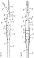
- the actuation rod (114) may be advanced to begin advancing the actuation rod (114) and locking sheath (116) into the lumen (212) of the barrel portion (210) of the grasper (200).
- the actuation rod (114) may be sized such that it is smaller than each of the proximal segment (214), the distal segment (216), and the intermediate segment (218) of the lumen (212) of the barrel portion (210) of the grasper (200). This may allow the actuation rod (114) to be advanced through the entire lumen (212) of the barrel portion (210).
- the locking sheath (116) may resist both advancement of the locking sheath (116) into the distal segment (216) (as discussed above) and withdrawal of the locking sheath (116) though the proximal segment (214) of the lumen (212). Accordingly, the expanded locking sheath (116) may lock the grasper (200) in place relative to the delivery device (100).
- the actuation rod (114) may apply one or more forces to the grasper (200) which may have a tendency to push the grasper (200) away from the coupling magnet (118) (which in some instances could possibly inadvertently decouple the grasper (200) from the delivery device (100)), but the engagement between the expanded locking sheath (116) and the grasper (200) may overcome these forces to maintain the position of the grasper (200) relative to the delivery device (100).
- the actuation rod (114) may be retracted until the indentations (130) of the actuation rod (114) reach the internal projections (128) of the locking sheath (116).
- the expandable distal portion (126) of the locking sheath (116) may be biased toward an unexpanded state such that the internal projections (128) reposition themselves into their respective indentations (130), as shown in FIG. 2D .
- the actuation rod (114) may then be withdrawn to withdraw the locking sheath (116) (e.g., by virtue of the connection between the indentations (130) and the internal projections (128)).
- proximal arm (220) may be exposed relative to the main body (206), which may allow a grasping device to grasp the proximal arm (220) to rotate the first jaw (202) relative to the second jaw (204).
- opposing forces represented by arrows (222) in FIG. 2A
- opposing forces may be applied (e.g., via a grasping device) to the exposed portion of the proximal arm (220) and the main body (206) to cause the proximal arm (220) to rotate around the pivot point (208) (which may in turn rotate the first jaw (202) away from the second jaw (204)).
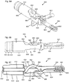
- FIGS. 3A and 3B depict cross-sectional side views of one such variation of a grasper (300) which may be used with the systems described here.
- the grasper (300) may comprise a first jaw (302), a second jaw (304), and a main body (306).
- the first jaw (302) may be rotatably coupled to the main body (306) at a pivot point (308), and the main body (306) of the grasper (300) may comprise a barrel portion (310) having a lumen (312) extending therethrough.
- the eccentric cam member (422) may be rotated via a portion of a delivery device that may be advanced through the lumen (412) of the barrel portion (410) of the grasper (400).
- the delivery device (100) described above may actuate the grasper (400).
- the distal engagement portion (108) of the delivery device (100) may engage the barrel portion (410) of the grasper (400) (as discussed in more detail above), and the actuation rod (114) may be advanced through the lumen (412) of the barrel portion (410) until the actuation rod (114) contacts the eccentric cam member (422) (which may be aligned with the lumen (412)), such as shown in FIG. 4A .
- actuation rod (114) may push against the eccentric cam member (422), which may convert the linear movement of the actuation rod (114) into rotational movement of the eccentric cam member (422).
- the first jaw (402) may rotate away from the second jaw (404), as depicted in FIG. 4B .
- the first jaw (402) may be biased to rotate back toward the second jaw (404). Accordingly, the actuation rod (114) may be advanced and withdrawn to cause the first jaw (402) to rotate away from and toward, respectively, the second jaw (404).
- the actuation rod (114) may be advanced and withdrawn in any suitable manner.
- the delivery device (100) comprises an actuation control mechanism, such as a slider, knob, trigger, or the like
- the actuation control mechanism may be operatively connected to the actuation rod (114) such that the actuation control mechanism may advance and withdraw the actuation rod (114).
- the trigger (112) may be configured to advance and retract the actuation rod (114).
- the first jaw (602) and the second jaw (604) may be held in rotationally separated positions to define a space between the first jaw (602) and the second jaw (604), as shown in FIG. 6A .
- the first jaw (602) and second jaw (604) may be rotationally biased toward each other, as shown in FIG. 6B . While the first jaw (602) is shown as contacting the second jaw (604) in FIG. 6B , it should be appreciated that when the grasper (600) is connected to tissue, tissue positioned between the first jaw (602) and the second jaw (604) may prevent the first jaw (602) from contacting the second jaw (604) when the grasper is in the closed configuration.
- the first jaw (602) and second jaw (604) may be rotationally biased toward a closed configuration in any suitable manner (e.g., via a torsional spring (not shown)), such as described in more detail above.
- the barrel portion (610) may further comprise a tapered portion (644) positioned between the first segment (640) and the second segment (642), such that the outer diameter of the tapered segment (644) tapers between the first outer diameter and the second outer diameter. It should be appreciated, however, that the barrel portion (610) need not have such a tapered portion (644), and the first segment (640) may immediately transition to the second segment (642). In variations that do include a tapered segment (644), the tapered segment (644) may provide a gradual diameter transition between the first (640) and second (642) segments, which may in turn reduce the presence of edges that may catch on or otherwise disturb tissue during use of the grasper (600).
- 6A-6C may comprise a curved arm (620) that may be configured to act as both a cam and a lever (similar to the proximal arm (220) of the grasper (200) discussed above with respect to FIGS. 1A-1C and 2A-2F ), it should be appreciated that the grasper may include any of the proximal arms and/or eccentric cam members discussed above with respect to FIGS. 3A-3B and 4A-4B .
- the proximal arm (620) (and/or an eccentric cam member) may assist in actuation of the grasper (600), as described hereinthroughout.
- any of these graspers may comprise a shuttle pin, which may be configured in any suitable manner as discussed with respect to shuttle pin (650) of the grasper (600) shown in FIGS. 6A-6C .
- the grasper may be configured to help prevent the shuttle pin from disengaging from the grasper.
- at least a portion of a shuttle pin may be configured to have an outer profile that is larger than at least a portion of the lumen of the barrel portion of a main body.
- the distal end (654) may comprise a cap (656) that may have an outer diameter sized to be larger than the lumen (612) of the barrel portion (610) of the main body (606).
- the shuttle pin (650) may be positioned in the lumen (612) such that the cap (656) is positioned distally of the lumen (612).
- the grasper (600) shown in FIGS. 6A-6C may be actuated in any suitable manner.
- the grasper (600) may be configured such that it may be actuated by a force applied internally of the grasper (600) (e.g., via an actuation rod of a delivery device advanced through the lumen (612) of the barrel portion (610) of the grasper (600), as discussed in more detail below), and may be further configured such that it may be actuated by a force applied externally of a grasper (600) (e.g., via a grasping device).
- the actuation control mechanism may be configured to both actuate the grasper (600) and the delivery device (700).
- the actuation control mechanism comprises a trigger
- the trigger may be moveable between three positions (although it should be appreciated that the trigger may assume one or more intermediate positions between these positions). Of the three positions, the trigger may be moveable between a first position (such as the position of the trigger (112) of the delivery device (100) shown in FIG. 1A ) and a second position (such as the position of the trigger (112) of the delivery device (100) as shown in FIG. 1B ) to close and open, respectively, the grasper (600).
- a first position such as the position of the trigger (112) of the delivery device (100) shown in FIG. 1A
- a second position such as the position of the trigger (112) of the delivery device (100) as shown in FIG. 1B
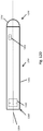
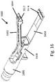
- a visualization device such as a camera (2100) may be configured to be temporarily coupled to the delivery device (700).
- the camera (2100) may have a capsule-like outer shape as shown, or may have any other suitable shape.
- the camera (2100) may comprise a lens.
- the lens may be located in any suitable location, such as but not limited to the distal end of the camera (2100), or along a barrel portion (2110) of the camera.
- the camera (2100) may comprise one or more magnetic elements, which may be located, for example, at an end of the camera or along a barrel portion.
- the actuation rod (714) may be advanced or retracted relative to the shaft (706) to actuate and/or eject the grasper (600).
- the handle comprises a trigger (such as discussed above)
- the trigger may be operatively connected to the actuation rod (714), such that movement of the trigger slides the actuation rod (714). Movement of the actuation rod (714) may rotate the first jaw (602) of the grasper (600).
- the actuation rod (714) may be aligned with the lumen (612) of the barrel portion (610) such that the actuation rod (714) enters the lumen (612).
- tissue when the jaws are used to grasp tissue therebetween, tissue may be squeezed or captured into or otherwise enter the recess of each jaw, which may help to provide a more secure hold between the grasper and the tissue.
- the size and placement of the recesses may also influence the effect of a magnetic field on the graspers, as described in more detail below.
- using both magnetic and non-magnetic materials may affect which portions of the grasper or visualization device (e.g., camera, light source) are attracted to, unaffected by, or repelled by magnetic fields generated by the control element (and may affect which portions of the grasper or visualization device may create magnetic fields that may attract, not affect, or repel portions of the control element).
- portions of the grasper or visualization device e.g., camera, light source
- portions of the grasper or visualization device may affect which portions of the grasper or visualization device (e.g., camera, light source) are attracted to, unaffected by, or repelled by magnetic fields generated by the control element (and may affect which portions of the grasper or visualization device may create magnetic fields that may attract, not affect, or repel portions of the control element).
- a portion of the grasper may be made from plastic (e.g., both jaws, one jaw, a distal portion of one or both jaws, a proximal portion of one or both jaws, a combination thereof, or the like) while the remainder of the grasper may comprise a ferromagnetic material.
- the plastic portion of the grasper will not attract surgical tools, but the grasper may still be controlled using an external control element.
- the grasper may comprise a magnetic element comprising a ferromagnetic or ferrimagnetic material (e.g., iron, cobalt, nickel, and the like) that is attracted to a magnetic field but does not independently generate a magnetic field
- the control element may comprise a magnetic element (e.g., a permanent magnet) that generates a magnetic field that attracts the ferromagnetic or ferrimagnetic material.
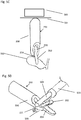
- control element (816) located outside of the body.
- the control element (816) is depicted as a magnet comprising poles that face toward and away from the cavity wall (822). As depicted, the north pole of the control element (816) faces downward, or toward the cavity wall (822), and the south pole of the control element (816) faces upward, or away from the cavity wall (822). While the control element (816) is depicted as a magnet itself, it need not be.
- the control element (816) may comprise a combination of one or more non-magnetic materials (e.g., plastics, paramagnetic materials such as titanium, and the like) and one or more magnets.
- the control element (916) may be used to control and/or maneuver the grasper (900A, 900B).
- the graspers (900A, 900B) may comprise a first jaw (902A, 902B), a second jaw (904A, 904B), a main body (906A, 906B), a longitudinal axis (914A, 914B), a distal end (908A, 908B), a proximal end (910A, 910B), and a magnetic element (912A, 912B).
- one jaw may be made from a non-magnetic material, while the other jaw may be made partially from a ferromagnetic material and partially from a non-magnetic material (e.g., a distal end may be made from a non-magnetic material).
- the rotatable jaw may be made from a non-magnetic material, while the fixed jaw may be made partially from a ferromagnetic material and partially from a non-magnetic material.
- the magnetic element (912B), the second material (924B), and the third material (926) need not have the same mass, and it may be desirable to vary the mass of the materials (912B, 924B, 926) to achieve better control over the grasper (900B). For example, varying the mass in different portions of the grasper may also vary the gravitational force that may counteract an attractive force between a specific portion of the grasper and the control element.
- decreasing the mass of some portions of the grasper may also decrease the attractive force between that portion and the control element.
- the second and/or third material (924B, 926) may also comprise magnetic elements.
- the second and/or third materials (924B, 926) may be materials that experience a repulsive force when exposed to the control element (916). It should be appreciated that the second and third materials (924B, 926) need not be in the locations or proportions indicated in FIG. 9B , and may instead have any locations and proportions that facilitate maneuvering the grasper (900B) with the control element (916).
- FIG. 9C depicts the grasper (900A) of FIG. 9A in use with a control element (916) comprising a longitudinal axis (920).
- a cross-sectional side view of the cavity wall (922) can also be seen, with the grasper (900A) located within the body, and the control element (916) located outside of the body.
- the attractive force between the control element (916) and the magnetic element (912A) may move the proximal end (910A) of the grasper (900A) towards the control element (916).
- the grasper (900A) may then be in a similar perpendicular position to that described with respect to FIG. 8B .
- the system of the invention as claimed uses repulsive forces.
- FIG. 10A depicts a cross-sectional side view of a variation of a grasper (1000) configured to be used with a control element located outside of the body to place the grasper in a parallel configuration.
- FIG. 10A depicts a cross-sectional side view of a variation of a grasper (1000) configured to be used with a control element located outside of the body to place the grasper in a parallel configuration.
- FIGS. 10B and 10C depict variations of a system comprising a control element (1016, 1026) and the grasper (1000) of FIG. 10A in a parallel configuration.
- FIG. 10A depicts a cross-sectional side view of a variation of a grasper (1000) configured to be used with a control element located outside of the body to place the grasper in a parallel configuration.
- the remainder of the grasper (1000) (aside from the magnetic element (1012)) including, for example, the remainder of the main body (1006) and the first and second jaws (1002, 1004), may comprise a non-magnetic material, ferromagnetic material, ferrimagnetic material, a combination thereof, or the like.
- the grasper (1000) may comprise a second magnetic element in a portion of the remainder of the grasper (1000) that may comprise a material that experiences a repulsive force when exposed to a magnetic field generated by the control element (1016, 1026) (e.g., a diamagnetic material).
- the north and south poles may be positioned along the longitudinal axis (1020) of the control element (1026).
- the south pole faces the proximal end of the control element (1016) (i.e., the left side as depicted in FIG. 10B ) and the north pole faces the distal end of the control element (1016) (i.e., the right side as depicted in FIG. 10B ).
- the attractive force between the control element (1016) and the magnetic element (1012) may move the grasper (1000) toward the control element (1016) such that the longitudinal axis (1014) of the grasper is substantially parallel to the longitudinal axis (1020) of the control element. More specifically, the north and south poles of the magnetic element (1012) in the grasper (1000) may be attracted to the south and north poles, respectively, of the magnetic element (1024) in the control element (1016).
- the magnetic element (1012) of the grasper (1000) is of a sufficient length, or is spread along the grasper across a sufficient length, to cause both the proximal and distal ends (1010, 1008) of the grasper (1000) to be drawn to the control element (1016) and the cavity wall (1022).
- the longitudinal axis (1014) of the grasper (1000) may be substantially parallel to both the longitudinal axis (1020) of the surface of the cavity wall such that the first and second jaws (1002, 1004) are near the cavity wall.
- the direction of the jaws may be manipulated by rotating the control element, which may in turn cause rotation of the magnetic element (1012) in the grasper (1000).
- the configurations of the magnetic elements (1012, 1028, 1030) may be modified.
- the poles of the first and second magnetic elements (1028, 1030) and the magnetic element (1012) of the grasper (1000) may be rotated such that they face the opposite direction (e.g., the north pole of the first magnetic element (1028) may be posteriorly positioned and the north pole of the second magnetic element (1030) may be anteriorly positioned).
- the magnetic elements (1012, 1028, 1030) may have any suitable shape, and need not be cylinders as depicted.
- the magnetic elements (1112, 1124) may be positioned within the grasper (1100) and the control element (1116) so that their poles are perpendicular to the longitudinal axis of the grasper (1100) and the control element (1116) respectively, and are parallel to the cavity wall (1122).
- the north pole of the magnetic element (1124) of the control element (1116) may face the right side of the patient and the south pole of the magnetic element (1124) of the control element (1116) may face the left side of the patient, or vice versa.
- the north and south poles of the magnetic element (1112) of the grasper (1100) may be attracted to the south and north poles of the magnetic element (1124) of the control element (1116) respectively, which may bring the grasper (1100) into a parallel configuration.
- the grasper (1100) While in the parallel configuration, the grasper (1100) may be in a first orientation in which its proximal end (1110) faces a first direction and its distal end (1108) faces a second direction.
- a visualization device such as a camera and/or light source may also have a similar configuration of magnetic elements as described with respect to graspers in FIGS. 8A-11C .
- a visualization device having a similar configuration of magnetic elements as grasper (800) may be used with a control element (816) similar to as shown in FIGS. 8A-8B in order to hold and/or move a visualization device in a perpendicular or angled configuration with respect to the control element and/or the wall of a patient's body cavity.
- a visualization device may comprise a magnetic element comprising a magnet with north and south poles oriented axially within the visualization device, such that the poles are positioned along a longitudinal axis of the visualization device, as described above with respect to grasper (800).
- Control element (816) may then be used to control the position and/or movement of the visualization device similarly as described with respect to the grasper (800).
- a visualization device having similar configuration of magnetic elements as grasper (1000) and may be used with a control element (1000) similar to as shown in FIGS. 10A-10B in order to hold and/or move the visualization device in a parallel configuration, as described in more detail with respect to grasper (1000).
- the grasper may comprise more than one magnetic element.
- a visualization device e.g., camera, light source
- a grasper (or visualization device) with multiple magnetic elements may provide more control over the movement of the grasper, especially with respect to relative locations of the proximal and distal ends of the grasper (or visualization device). For instance, utilizing a grasper (or visualization device) with multiple magnets may make it easier to rotate the distal end of the grasper (or visualization device) relative to its proximal end and may allow for better control over the grasper (or visualization device) once it is in the parallel configuration.
- a grasper (or visualization device) with multiple magnetic elements may make it easier to attract the proximal and/or distal end of the grasper (or visualization device) to the control element (e.g., by repelling the opposite end) and/or control the angle at which the grasper (or visualization device) approaches the control element and/or tissue (e.g., perpendicular, parallel, any angle between perpendicular and parallel).
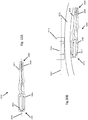
- FIGS. 12A-12C depict a variation of the systems described here comprising a grasper (1200) with two magnetic elements (1212, 1232) and a control element (1206).
- the grasper (1200) may comprise a first jaw (1202), a second jaw (1204), a main body (1206), a proximal end (1210), a distal end (1208), a longitudinal axis (1214), a first magnetic element (1212), and a second magnetic element (1232).
- the first magnetic element (1212) may be located at the proximal end (1210) of the grasper (1200) in the main body (1206), and the second magnetic element (1232) may be located distal to the first magnetic element (1212), for example, in the first jaw (1202).
- the magnetic elements (1212, 1232) may exert forces on each other, placing them farther away from each other, or with more non-magnetic material between them, may decrease any unwanted effect they may have on each other and/or on the grasper (1200).
- the first and second magnetic elements (1212, 1232) may have any suitable cross-sectional shape, for example, circle, square, oval, rectangle, hexagon, and the like, and need not comprise the same cross-sectional shape.
- the magnetic elements (1212, 1232) need not be and may comprise any of the magnetic elements described above that result in attractive forces between the magnetic elements (1212, 1232) in the grasper (1200) and the magnetic elements (1228, 1230) in the control element (1216).
- the magnetic elements (1262, 1282) may exert forces on each other, placing them farther away from each other, or with more non-magnetic material between them, may decrease any unwanted effect they may have on each other and/or on the camera (1250).
- the first and second magnetic elements (1262, 1282) may have any suitable cross-sectional shape, for example, circle, square, oval, rectangle, hexagon, and the like, and need not comprise the same cross-sectional shape.
- the camera (1250) may be moved relative to the cavity wall by a corresponding amount by the attractive forces between the magnetic element (1262) and the control element (1216).
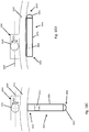
- the magnetic element (1812) may comprise a magnet with north and south poles oriented axially within the grasper (1800) such that the poles are positioned along a longitudinal axis of the grasper (1800). More particularly, the south pole of the magnetic element (1812) faces a proximal end (1810) of the grasper (1800) and the north pole faces a distal end (1808) of the grasper (1800). Shown in FIG. 18A is the grasper (1800) within the body and separated from a control element (1816) by the body cavity wall (1822). The control element (1816) is provided outside the body and comprises a longitudinal axis (1820).
- the attractive forces between the magnetic element (1812) in the grasper (1800) and the control element housing (1816) may cause the proximal end (1810) of the grasper (1800) to be attracted to and move toward the control element housing (1816) and the cavity wall (1822), while the distal end (1808) of the grasper (1800) may be repelled by and move away from the control element housing (1816) and the cavity wall (1822). Accordingly, the attractive forces between the magnetic element (1812) and the control element housing (1816) may cause the grasper (1800) to rotate and/or move into a position in which its longitudinal axis is transverse, and substantially perpendicular to, the surface of the cavity wall (1822) and longitudinal axis (1820) of the control element housing (1816). In this position, the first and second jaws (1802, 1804) of the grasper (1800) may be facing away from the cavity wall (1822).
- FIG. 18B depicts a second configuration of the magnet housing (1824) where the north and south poles are oriented along the longitudinal axis (1820) of the control element housing (1816).
- the north pole of the magnetic element (1812) faces the proximal end of the control element housing (1816) (i.e., the left side as depicted in FIG. 18B ) and the south pole of the magnetic element (1812) faces the distal end of the control element housing (1816) (i.e., the right side as depicted in FIG. 18B ).
- the attractive force between the control element housing (1816) and the magnetic element (1812) may move the grasper (1800) toward the control element housing (1816) in a second position such that the grasper (1800) may be substantially parallel to the longitudinal axis (1820) of the control element housing (1816). More specifically, the north and south poles of the magnetic element (1812) in the grasper (1800) may be attracted to the south and north poles, respectively, of the magnet in the magnet housing (1824). As such, as the magnet housing (1824) of the control element housing (1816) is rotated from a first configuration ( FIG. 18A ) to the second configuration ( FIG. 18B ), the change in the magnetic field will likewise rotate the grasper (1800) from a first position perpendicular to the cavity wall (1822) to a second position parallel to the cavity wall (1822).
- a change in configuration of a grasper may be provided through a combination of manipulation of the entire control element housing (1816) relative to the grasper and of a magnet relative to the control element housing.
- FIG. 18C depicts a variation of a system comprising a control element (1816) and a visualization device comprising a camera (1850) positioned in a perpendicular configuration relative to the cavity wall (1822).
- FIG. 18B depicts the camera (1850) positioned in a substantially parallel configuration relative to the cavity wall (1822).
- FIGS. 19A-19B depict a variation of a system comprising a grasper (1900) comprising a magnetic element (1912).
- the control element may comprise a control element housing (1916) enclosing a magnet housing (1924) comprising a magnet.
- the magnetic element (1912) and magnet housing (1924) may each comprise magnets each having a north pole and a south pole.
- the magnetic element (1912) and magnet housing (1924) may be positioned within the grasper (1900) and the control element housing (1916), respectively, so that their poles are perpendicular to the longitudinal axis (1920) of the grasper (1900) and the control element housing (1916) respectively.
- the grasper and control element may be placed such that the poles are parallel to the cavity wall (1922).
- FIG. 19A depicts the orientation of the magnetic element (1912) and magnet housing (1924) in the grasper (1900) and the control element housing (1916), respectively. Shown there is a view from within a patient's body cavity. Grasper (1900) is shown within the body cavity, and the control element housing (1916), indicated by dashed lines, is shown outside of the body and above the cavity wall (1922). In use, the north pole of the magnetic element (1912) of the grasper may be attracted to the south pole of the magnet housing (1924) of the control element housing (1916), which may pull or otherwise move the grasper (1900) toward, and substantially parallel to, the cavity wall (1922).
- the north pole of the magnet housing (1924) of the control element housing (1916) may face the right side of the patient and the south pole of the magnet housing (1924) of the control element housing (1916) may face the left side of the patient, or vice versa.
- the north and south poles of the magnet housing (1912) of the grasper (1900) may be attracted to the south and north poles of the magnet housing (1924) of the control element housing (1916) respectively, which may bring the grasper (1900) into a parallel configuration.
- the grasper (1900) While in the parallel configuration, the grasper (1900) may be in a first orientation in which its proximal end (1910) faces a first direction and its distal end (1908) faces a second direction.
- the grasper (1900) may be rotated while remaining in the parallel configuration by rotating (arrow 1930) magnet (1924) relative to the control element housing (1916).
- the grasper (1900) may be rotated by 180 degrees to place it in a second orientation in which its proximal end (1910) faces the second direction and its distal end (1908) faces the first direction.
- FIG. 19B illustrates the grasper (1900) rotated (1930) by 90 degrees by rotation of the magnet housing (1924) relative to the control element housing (1916) such that the longitudinal axis of the grasper (1900) is perpendicular to the longitudinal axis (1920) of the control element housing (1916).
- the grasper (1900) may be rotated by any desired angle while remaining in the substantially parallel configuration by rotating the magnet housing (1924) relative to the control element housing (1916).
- the magnet housing (1924) and control element housing (1916) need not have the cross-sectional shapes as depicted in FIGS. 19A-19B , and may have any configuration that allows rotation of the magnet relative to the control element.
- control element and the visualization device may be configured such that the control element can cause the visualization device to rotate about an axis perpendicular to a cavity wall to provide the visualization device yaw rotation where, for example, the visualization device maintains a parallel configuration relative to the internal wall of the patient's body cavity or the surface of the control element.
- control element may be configured to cause roll rotation of the visualization device about the longitudinal axis of the visualization device while the visualization device is perpendicular to the cavity wall.
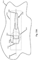
- FIG. 20 depicts an illustrative variation of a control element providing a variable magnetic field.
- the control element (2000) comprises a magnet that rotates relative to the control element housing such that the control element may be stationary as the magnetic field applied to a grasper is modified.
- a control element (2000) may comprise a control element housing (2002) enclosing a magnet housing (2012) comprising a magnet (2010) and a magnet control (2014). Movement of the magnet control (2014) within a control element opening (2004) may provide corresponding rotation of the magnet housing (2012) and in turn the magnet (2010).
- the magnet (2010) may comprise a diamagnetic material and may comprise opposing north and south poles.
- the control element housing (2002) may have one or more openings that define a range of motion of the magnet control (2014). In FIG. 20 , movement of the magnet control (2014) through its range of motion will rotate the magnet (2010) by 90 degrees to change the direction of the poles.
- one or more of the magnet (2010) and magnet housing (2012) may comprise a sphere, bar, axially-magnetized cylinder, or a set of magnets.
- the magnet (2010) illustrated in FIG. 20 may be rotated about a longitudinal axis of the control element (2000).
- the poles may be oriented axially within the control element (2000) such that the poles are positioned along a longitudinal axis of the control element (2000).
- the magnet (2010) may have additional degrees of freedom.
- the magnet housing (2012) may be spherical and the magnet control (2014) may be manipulated to provide three degrees of freedom. If the control element opening (2004) is spherical for example, then the magnet control (2014) may be manipulated like a joystick.
- the magnet housing (2012) and control element housing (2002) may comprise different shapes and/or materials.
- the magnet (2010) and magnet housing (2012) may comprise any shape that allows rotation and/or movement relative to the control element (2000).
- FIGS. 8A-12C , 18A-18B , and 19A-19B any suitable grasper, visualization device, and/or delivery systems described here may be configured with magnetic and non-magnetic materials as described in FIGS. 8A-12D and 18A-19B .
- the magnetic and non-magnetic materials described with respect to FIGS. 8A-12D and 18A-19B may be designed to work concurrently with the delivery devices described above, and in some variations, the coupling magnet and the magnetic element may comprise the same material and/or be the same magnet.
- the graspers, visualization devices (e.g., cameras, light sources), and systems described herein may be used in minimally invasive procedures. These may include any suitable minimally invasive procedure, such as but not limited to abdominal procedures, thorascopic procedures, bariatric procedures, or urological/gynecological procedures.
- a grasper as described herein may be advanced into the body, may be releasably connected to a tissue in the body, and may be suspended using one or more magnetic elements positioned externally to the body to move and suspend the tissue.
- the connection between the grasper and the tissue may be released, and the grasper may be repositioned and reconnected to tissue (either the same tissue or different tissue).
- a visualization device such as a camera and/or light source as described herein may be advanced into the body, and may be suspended using one or more magnetic elements positioned externally to the body.
- the grasper may be advanced into the body in any suitable manner.
- the grasper may be advanced into the body through a port as part of a minimally invasive procedure.
- the minimally invasive procedure may be a reduced port technique or single-incision procedure.
- the grasper may be advanced into the body using a delivery device, such as the delivery device (100) described above with respect to FIGS. 1A-1C and 2A-2F .
- the grasper may be releasably coupled to a distal engagement portion of the delivery device, and the distal engagement portion of the delivery device may be advanced into the body to advance and position the grasper within the body.
- the grasper (200) may be advanced into the body toward a target tissue (502) (shown in FIG. 5 as a gallbladder, although it should be appreciated that the graspers described here may be releasably connected to any suitable tissue), and positioned in an open configuration.
- a target tissue 502
- the grasper (200) may be releasably coupled to a distal engagement portion (108) of a delivery device (100), and a user may advance the distal engagement portion (108) into the body to position the grasper (200).
- FIG. 5D shows a grasping device (506) having opposing jaws (508) which may grab a proximal arm (220) and the main body (206) of the grasper (200) to rotate the first jaw (202) away from the second jaw (204), which may release the tissue (502) from the grasper (200).
- the grasper (200) may be repositioned to again place the tissue (502) between the jaws (202, 204) of the grasper (200), and the grasper (200) may then be placed in the closed configuration to reconnect the grasper (200) to the tissue (502).
- the grasper may release the tissue, be repositioned at a second tissue, and may then be placed in the closed configuration to connect to the second tissue.
- the grasper (200) may be decoupled from the tissue, and removed from the body.
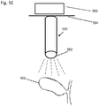
- a visualization device comprising a camera (550) may be advanced into the body with a lens (552) directed towards a target tissue (502) (shown in FIG. 5E as a gallbladder, although it should be appreciated that the cameras described here may image any tissue).
- the camera (550) may be releasably coupled to a distal engagement portion of a delivery device, and a user may advance the distal engagement portion into the body to position the camera (550). Once in position, the camera (550) may be released from the delivery device, and the delivery device may be removed from the body.
- Some exemplary methods may involve the delivery of two or more graspers as described herein.
- a first grasper may be advanced into the body through a port using a delivery device, releasably connected to tissue (either by gripping the tissue or by capturing it in a space between the jaws), and released from the delivery device.
- a first control element may then be positioned externally of the body to attract and lift the first grasper toward the first control element.
- a second grasper may be advanced into the body through the same port (or a second port) using the same delivery device (or a second delivery device), releasably connected to tissue (either by gripping the tissue or by capturing it in a space between the jaws), and released from the delivery device.
- a second control element may then be positioned externally to the body to attract and lift the second grasper toward the second control element.
- the graspers (1702, 1704) may each hold different portions of the same tissue (1716) (e.g., colon), although it should be appreciated that the graspers (1702, 1704) may hold distinct pieces of tissue.
- more than two graspers may be used in the same procedure, such as but not limited to three, four, five, or six graspers, or more.
- the methods may comprise delivery of one or more graspers in combination with one or more additional instruments (e.g., one or more visualization devices such as camera and/or light source), delivery of two or more visualization devices, or the like.
- a camera may be advanced into the body through a port using a delivery device and released from the delivery device.
- a control element may then be positioned externally of the body to attract and lift the camera toward the first control element.
Claims (15)
- Système de préhension de tissu, comprenant :une pince (800) comprenant une extrémité proximale (810), une extrémité distale (808) et un axe longitudinal (814), et dans lequel la pince (800) comprend en outre un premier élément magnétique (812) à l'extrémité proximale (810) ; etun élément de commande (816) séparé de la pince (800) et configuré pour repousser au moins une partie de la pince (800), dans lequel l'élément de commande (816) comprend un deuxième élément magnétique (1030) et un axe longitudinal (820),dans lequel les premier et deuxième éléments magnétiques (812, 1030) sont configurés pour repousser l'extrémité proximale (810) de la pince (800) à l'opposé de l'élément de commande (816) de telle façon que l'axe longitudinal de la pince (814) est transversal à l'axe longitudinal de l'élément de commande (820).
- Système selon la revendication 1, dans lequel l'extrémité distale (808) de la pince (800) comprend un matériau amagnétique ou diamagnétique.
- Système selon la revendication 2, dans lequel l'extrémité distale (808) de la pince (800) comprend du plastique.
- Système selon la revendication 1, dans lequel l'extrémité distale (808) de la pince (800) comprend un matériau non conducteur.
- Système selon la revendication 1, dans lequel le premier élément magnétique (812) est un matériau ferromagnétique.
- Système selon la revendication 5, dans lequel le matériau ferromagnétique est un acier inoxydable.
- Système selon la revendication 1, dans lequel le premier élément magnétique (812) comprend un aimant permanent.
- Système selon la revendication 1, dans lequel la pince (800) comprend une configuration fermée et une configuration ouverte et dans lequel, dans la configuration fermée, la première mâchoire (802) et la deuxième mâchoire (804) forment un espace configuré pour maintenir un tissu.
- Système selon la revendication 1, dans lequel la pince (800) comprend en outre un corps principal (806), une première mâchoire (802) couplée de manière rotative au corps principal (806), et une deuxième mâchoire (804) fixe par rapport au corps principal (806).
- Système selon la revendication 1, dans lequel le deuxième élément magnétique (1030) est configuré pour tourner par rapport à l'élément de commande (816).
- Système selon la revendication 1, dans lequel le deuxième élément magnétique (1030) comprend un matériau diamagnétique.
- Système selon la revendication 1, dans lequel le premier élément magnétique (812) comprend une orientation polaire pratiquement perpendiculaire à l'axe longitudinal de la pince (814).
- Système selon la revendication 1, dans lequel l'extrémité distale (808) de la pince (800) comprend un troisième élément magnétique, dans lequel le premier élément magnétique (812) a une première polarité et le troisième élément magnétique a une deuxième polarité opposée à la première polarité.
- Système selon la revendication 1, dans lequel le premier élément magnétique (812) comprend une orientation polaire pratiquement parallèle à l'axe longitudinal de la pince (814).
- Système selon la revendication 1, dans lequel la pince (800) comprend un troisième élément magnétique et l'élément de commande (816) comprend un quatrième élément magnétique.
Priority Applications (1)
| Application Number | Priority Date | Filing Date | Title |
|---|---|---|---|
| EP21187437.5A EP3954303A1 (fr) | 2015-04-13 | 2016-04-13 | Pince à positionnement commandé magnétiquement |
Applications Claiming Priority (3)
| Application Number | Priority Date | Filing Date | Title |
|---|---|---|---|
| US201562146922P | 2015-04-13 | 2015-04-13 | |
| US201662276752P | 2016-01-08 | 2016-01-08 | |
| PCT/US2016/027390 WO2016168380A1 (fr) | 2015-04-13 | 2016-04-13 | Pince à positionnement commandé magnétiquement |
Related Child Applications (1)
| Application Number | Title | Priority Date | Filing Date |
|---|---|---|---|
| EP21187437.5A Division EP3954303A1 (fr) | 2015-04-13 | 2016-04-13 | Pince à positionnement commandé magnétiquement |
Publications (3)
| Publication Number | Publication Date |
|---|---|
| EP3282954A1 EP3282954A1 (fr) | 2018-02-21 |
| EP3282954A4 EP3282954A4 (fr) | 2018-12-05 |
| EP3282954B1 true EP3282954B1 (fr) | 2021-07-28 |
Family
ID=57126303
Family Applications (2)
| Application Number | Title | Priority Date | Filing Date |
|---|---|---|---|
| EP16780691.8A Active EP3282954B1 (fr) | 2015-04-13 | 2016-04-13 | Pince à positionnement commandé magnétiquement |
| EP21187437.5A Pending EP3954303A1 (fr) | 2015-04-13 | 2016-04-13 | Pince à positionnement commandé magnétiquement |
Family Applications After (1)
| Application Number | Title | Priority Date | Filing Date |
|---|---|---|---|
| EP21187437.5A Pending EP3954303A1 (fr) | 2015-04-13 | 2016-04-13 | Pince à positionnement commandé magnétiquement |
Country Status (4)
| Country | Link |
|---|---|
| US (2) | US10905511B2 (fr) |
| EP (2) | EP3282954B1 (fr) |
| ES (1) | ES2895900T3 (fr) |
| WO (1) | WO2016168380A1 (fr) |
Families Citing this family (22)
| Publication number | Priority date | Publication date | Assignee | Title |
|---|---|---|---|---|
| CA2942567C (fr) | 2007-11-26 | 2021-08-17 | Attractive Surgical, Llc | Systeme et procede de magnaretraction |
| CL2009000279A1 (es) | 2009-02-06 | 2009-08-14 | Biotech Innovations Ltda | Sistema de guia y traccion remota para cirugia mini-invasiva, que comprende: al menos una endopinza quirurgica y desprendible con medios de enganches y una porcion de material ferro magnaetico, una guia de introduccion de forma cilindrica, un mecanismo de desprendimiento, y al menos un medio de traccion remota con iman. |
| US9014787B2 (en) | 2009-06-01 | 2015-04-21 | Focal Therapeutics, Inc. | Bioabsorbable target for diagnostic or therapeutic procedure |
| EP2482736B1 (fr) | 2009-10-03 | 2018-08-01 | Hadasit Medical Research Services and Development Ltd. | Antenne transdermique |
| US20130289389A1 (en) | 2012-04-26 | 2013-10-31 | Focal Therapeutics | Surgical implant for marking soft tissue |
| US8764769B1 (en) | 2013-03-12 | 2014-07-01 | Levita Magnetics International Corp. | Grasper with magnetically-controlled positioning |
| US10010370B2 (en) | 2013-03-14 | 2018-07-03 | Levita Magnetics International Corp. | Magnetic control assemblies and systems therefor |
| WO2015112645A1 (fr) | 2014-01-21 | 2015-07-30 | Levita Magnetics International Corp. | Moyens de préhension laparoscopique et systèmes associés |
| US9615915B2 (en) | 2014-07-25 | 2017-04-11 | Focal Therapeutics, Inc. | Implantable devices and techniques for oncoplastic surgery |
| EP3282923B1 (fr) | 2015-04-13 | 2021-08-11 | Levita Magnetics International Corp. | Dispositifs d'écarteur |
| EP3282954B1 (fr) | 2015-04-13 | 2021-07-28 | Levita Magnetics International Corp. | Pince à positionnement commandé magnétiquement |
| US11020137B2 (en) | 2017-03-20 | 2021-06-01 | Levita Magnetics International Corp. | Directable traction systems and methods |
| US10765442B2 (en) * | 2017-04-14 | 2020-09-08 | Ethicon Llc | Surgical devices and methods for biasing an end effector to a closed configuration |
| US10932804B2 (en) | 2017-10-30 | 2021-03-02 | Ethicon Llc | Surgical instrument with sensor and/or control systems |
| US11116485B2 (en) | 2017-10-30 | 2021-09-14 | Cilag Gmbh International | Surgical instrument with modular power sources |
| US11129634B2 (en) * | 2017-10-30 | 2021-09-28 | Cilag Gmbh International | Surgical instrument with rotary drive selectively actuating multiple end effector functions |
| US11793535B2 (en) | 2018-03-28 | 2023-10-24 | Zhangfan Mao | Endoluminal surgery device |
| KR20210047871A (ko) * | 2018-08-24 | 2021-04-30 | 네셔날 인더스트리 인포메이션 리서치 인스티튜트 씨오., 엘티디. | 파지기, 지침기, 협지장치 |
| CN110236613B (zh) * | 2019-06-14 | 2020-11-27 | 毛张凡 | 腔内手术器械 |
| WO2021088622A1 (fr) * | 2019-11-05 | 2021-05-14 | 江苏唯德康医疗科技有限公司 | Écarteur de tissu et tracteur médical doté de celui-ci |
| CN111772695A (zh) * | 2020-07-15 | 2020-10-16 | 深圳市资福医疗技术有限公司 | 一种微创手术的辅助装置 |
| CN111772694A (zh) * | 2020-07-15 | 2020-10-16 | 深圳市资福医疗技术有限公司 | 一种微创手术的辅助装置 |
Family Cites Families (338)
| Publication number | Priority date | Publication date | Assignee | Title |
|---|---|---|---|---|
| US2678228A (en) | 1951-06-08 | 1954-05-11 | Bausch & Lomb | Diagnostic instrument with magnetic connector |
| US2863444A (en) | 1956-08-21 | 1958-12-09 | Winsten Joseph | Liver retractor for cholecystectomies |
| US3146381A (en) | 1960-09-12 | 1964-08-25 | Vente D Aimants Allevard Ugine | Magnetic force control or switching system |
| SE336642B (fr) | 1969-10-28 | 1971-07-12 | Astra Meditec Ab | |
| US3794091A (en) | 1971-10-07 | 1974-02-26 | Med General Inc | Sterile sheath for surgical illuminator |
| US3789285A (en) | 1972-03-27 | 1974-01-29 | Handotai Kenkyu Shinkokai | Position control system using magnetic force |
| US4364377A (en) | 1979-02-02 | 1982-12-21 | Walker Scientific, Inc. | Magnetic field hemostasis |
| US4380999A (en) | 1980-07-15 | 1983-04-26 | Healy Keelin E | Stepped surgical retractor |
| US4756312A (en) | 1984-03-22 | 1988-07-12 | Advanced Hearing Technology, Inc. | Magnetic attachment device for insertion and removal of hearing aid |
| US4706668A (en) | 1985-09-16 | 1987-11-17 | B & B Tools | Aneurysm clip pliers |
| US4971067A (en) | 1988-05-05 | 1990-11-20 | Lee Bolduc | Biopsy instrument with a disposable cutting blade |
| US5154189A (en) | 1988-06-03 | 1992-10-13 | Oberlander Michael A | Method for repairing a torn meniscus |
| CA2004658C (fr) | 1988-06-03 | 1995-10-10 | Michael A. Oberlander | Clip arthroscopique et outil d'insertion |
| US5484437A (en) | 1988-06-13 | 1996-01-16 | Michelson; Gary K. | Apparatus and method of inserting spinal implants |
| DE8809501U1 (fr) | 1988-07-26 | 1988-11-24 | Schad, Karl, 7201 Kolbingen, De | |
| US4901405A (en) | 1988-08-25 | 1990-02-20 | Grover Alfred H | Self-aligning magnetic necklace clasp |
| US4968136A (en) | 1988-09-02 | 1990-11-06 | Northrop Corporation | Ring laser gyro and magnetic mirror therefor |
| US4915435A (en) | 1989-04-05 | 1990-04-10 | Levine Brian M | Mobile operating room with pre and post-operational areas |
| US5002557A (en) | 1989-04-06 | 1991-03-26 | Hasson Harrith M | Laparoscopic cannula |
| US5681260A (en) | 1989-09-22 | 1997-10-28 | Olympus Optical Co., Ltd. | Guiding apparatus for guiding an insertable body within an inspected object |
| US5797939A (en) | 1989-12-05 | 1998-08-25 | Yoon; Inbae | Endoscopic scissors with longitudinal operating channel |
| US5665100A (en) | 1989-12-05 | 1997-09-09 | Yoon; Inbae | Multifunctional instrument with interchangeable operating units for performing endoscopic procedures |
| US6099550A (en) | 1989-12-05 | 2000-08-08 | Yoon; Inbae | Surgical instrument having jaws and an operating channel and method for use thereof |
| US5156609A (en) | 1989-12-26 | 1992-10-20 | Nakao Naomi L | Endoscopic stapling device and method |
| US5454365A (en) | 1990-11-05 | 1995-10-03 | Bonutti; Peter M. | Mechanically expandable arthroscopic retractors |
| DE4024106C1 (fr) | 1990-07-30 | 1992-04-23 | Ethicon Gmbh & Co Kg, 2000 Norderstedt, De | |
| US5361752A (en) | 1991-05-29 | 1994-11-08 | Origin Medsystems, Inc. | Retraction apparatus and methods for endoscopic surgery |
| SE469432B (sv) | 1991-11-22 | 1993-07-05 | Nordiskafilt Ab | Vaevd beklaednad foer pappersmaskiner och liknande |
| US5282806A (en) | 1992-08-21 | 1994-02-01 | Habley Medical Technology Corporation | Endoscopic surgical instrument having a removable, rotatable, end effector assembly |
| JPH05245215A (ja) | 1992-03-03 | 1993-09-24 | Terumo Corp | 心臓ペースメーカ |
| CA2090980C (fr) | 1992-03-06 | 2004-11-30 | David Stefanchik | Applicateur d'agrafes a ligature |
| US5304183A (en) | 1992-03-23 | 1994-04-19 | Laparomed Corporation | Tethered clamp retractor |
| DE4212430C2 (de) | 1992-04-14 | 1998-01-22 | Franz Diemer | Vorrichtung zum Bergen von Körperorganen, insbesondere der Gallenblase |
| US5307805A (en) | 1992-07-10 | 1994-05-03 | Surgical Innovations I, L.P. | Surgical retractor assembly |
| CA2104345A1 (fr) | 1992-09-02 | 1994-03-03 | David T. Green | Dispositif a pince chirurgicale |
| US5300081A (en) | 1992-10-09 | 1994-04-05 | United States Surgical Corporation | Surgical clip applier having clip advancement control |
| US5304185A (en) | 1992-11-04 | 1994-04-19 | Unisurge, Inc. | Needle holder |
| US5450842A (en) | 1993-02-19 | 1995-09-19 | United States Surgical Corporation | Endoscopic surgical retractor |
| US5569274A (en) | 1993-02-22 | 1996-10-29 | Heartport, Inc. | Endoscopic vascular clamping system and method |
| US5417701A (en) | 1993-03-30 | 1995-05-23 | Holmed Corporation | Surgical instrument with magnetic needle holder |
| US5449361A (en) | 1993-04-21 | 1995-09-12 | Amei Technologies Inc. | Orthopedic cable tensioner |
| GB9309142D0 (en) | 1993-05-04 | 1993-06-16 | Gyrus Medical Ltd | Laparoscopic instrument |
| US5458603A (en) | 1993-05-12 | 1995-10-17 | Futch, Sr.; William A. | Elongated drive tool for prosthesis in body cavity |
| US5496333A (en) | 1993-10-20 | 1996-03-05 | Applied Medical Resources Corporation | Laparoscopic surgical clamp |
| US5397325A (en) | 1993-11-09 | 1995-03-14 | Badiaco, Inc. | Laparoscopic suturing device |
| US5499986A (en) | 1994-01-07 | 1996-03-19 | Smith & Nephew Richards Inc. | Quick release handle apparatus for removing and inserting intramedullary nails |
| US5415160A (en) | 1994-03-15 | 1995-05-16 | Ethicon, Inc. | Surgical lift method and apparatus |
| US5529568A (en) | 1994-03-18 | 1996-06-25 | Surgery Futures Research, Inc. | Magnetic operating table |
| US5824041A (en) | 1994-06-08 | 1998-10-20 | Medtronic, Inc. | Apparatus and methods for placement and repositioning of intraluminal prostheses |
| US5654864A (en) | 1994-07-25 | 1997-08-05 | University Of Virginia Patent Foundation | Control method for magnetic stereotaxis system |
| US5595562A (en) | 1994-11-10 | 1997-01-21 | Research Corporation Technologies, Inc. | Magnetic enteral gastrostomy |
| US6464710B1 (en) | 1995-03-06 | 2002-10-15 | Cook Urological Incorporated | Releasable, surgical clamp |
| US5538098A (en) | 1995-05-18 | 1996-07-23 | Trw Vehicle Safety Systems Inc. | Magnetically controlled retractor |
| US5733292A (en) | 1995-09-15 | 1998-03-31 | Midwest Orthopaedic Research Foundation | Arthroplasty trial prosthesis alignment devices and associated methods |
| DE19534618A1 (de) | 1995-09-18 | 1997-03-20 | Karl Schad | Chirurgisches Instrument |
| WO1997015234A1 (fr) | 1995-10-23 | 1997-05-01 | Johns Hopkins University | Instrument chirurgical |
| CN2244381Y (zh) | 1995-12-05 | 1997-01-08 | 罗菲尔(天津)医学工程有限公司 | 手术牵开器 |
| JPH09192137A (ja) | 1996-01-16 | 1997-07-29 | Takahiro Eguchi | 神経内視鏡に挿入可能で脱着可能な脳動脈瘤クリップ |
| US6099537A (en) | 1996-02-26 | 2000-08-08 | Olympus Optical Co., Ltd. | Medical treatment instrument |
| JP3776529B2 (ja) | 1996-02-29 | 2006-05-17 | オリンパス株式会社 | クリップ装置 |
| GB2313645B (en) | 1996-03-08 | 2000-04-26 | Marconi Gec Ltd | Levitation device |
| US5728121A (en) | 1996-04-17 | 1998-03-17 | Teleflex Medical, Inc. | Surgical grasper devices |
| US5722126A (en) | 1996-05-22 | 1998-03-03 | Romag Fasteners Inc. | Magnetic snap fasteners |
| US5782748A (en) | 1996-07-10 | 1998-07-21 | Symbiosis Corporation | Endoscopic surgical instruments having detachable proximal and distal portions |
| US5797911A (en) | 1996-09-24 | 1998-08-25 | Sdgi Holdings, Inc. | Multi-axial bone screw assembly |
| JPH10118200A (ja) | 1996-10-25 | 1998-05-12 | Nippon Koden Corp | 生体用磁気刺激装置 |
| US5848969A (en) | 1996-10-28 | 1998-12-15 | Ep Technologies, Inc. | Systems and methods for visualizing interior tissue regions using expandable imaging structures |
| US6331181B1 (en) | 1998-12-08 | 2001-12-18 | Intuitive Surgical, Inc. | Surgical robotic tools, data architecture, and use |
| US6017358A (en) | 1997-05-01 | 2000-01-25 | Inbae Yoon | Surgical instrument with multiple rotatably mounted offset end effectors |
| US5879297A (en) | 1997-05-08 | 1999-03-09 | Lucent Medical Systems, Inc. | System and method to determine the location and orientation of an indwelling medical device |
| DE19722062C2 (de) | 1997-05-27 | 1999-07-08 | Storz Karl Gmbh & Co | Zerlegbares medizinisches Instrument mit selbstorientierender Kupplung |
| IT1292016B1 (it) | 1997-05-28 | 1999-01-25 | Valerio Cigaina | Dispositivo di impianto particolarmente per elettrostimolazione e/o elettroregistrazione di visceri endoaddominali |
| US6015414A (en) | 1997-08-29 | 2000-01-18 | Stereotaxis, Inc. | Method and apparatus for magnetically controlling motion direction of a mechanically pushed catheter |
| US5849015A (en) | 1997-09-11 | 1998-12-15 | Bristol-Myers Squibb Company | Orthopaedic stem inserter with quick release lever and ratchet |
| US6311082B1 (en) | 1997-11-12 | 2001-10-30 | Stereotaxis, Inc. | Digital magnetic system for magnetic surgery |
| US6212419B1 (en) | 1997-11-12 | 2001-04-03 | Walter M. Blume | Method and apparatus using shaped field of repositionable magnet to guide implant |
| JP2001522623A (ja) | 1997-11-12 | 2001-11-20 | ステリオタクシス インコーポレイテツド | 可動結合化された磁気的誘導システム及び装置、及び、磁気を補助利用した手術のためにこれを用いる方法 |
| GB9803970D0 (en) * | 1998-02-26 | 1998-04-22 | Univ Birmingham | Method of applying a corrosion-resistant coating |
| AU3845099A (en) | 1998-05-15 | 1999-12-06 | Robin Medical Inc. | Method and apparatus for generating controlled torques on objects particularly objects inside a living body |
| US6315709B1 (en) | 1998-08-07 | 2001-11-13 | Stereotaxis, Inc. | Magnetic vascular defect treatment system |
| US6458146B1 (en) | 1998-10-22 | 2002-10-01 | East West Medical, Llp | Acupuncture treatment device and methods of use |
| US6241671B1 (en) | 1998-11-03 | 2001-06-05 | Stereotaxis, Inc. | Open field system for magnetic surgery |
| US6330467B1 (en) | 1999-02-04 | 2001-12-11 | Stereotaxis, Inc. | Efficient magnet system for magnetically-assisted surgery |
| US6173715B1 (en) | 1999-03-01 | 2001-01-16 | Lucent Medical Systems, Inc. | Magnetic anatomical marker and method of use |
| US6368338B1 (en) | 1999-03-05 | 2002-04-09 | Board Of Regents, The University Of Texas | Occlusion method and apparatus |
| DE19920869A1 (de) | 1999-05-06 | 2000-12-07 | Storz Karl Gmbh & Co Kg | Retraktor zur Verwendung in der endoskopischen Chirurgie sowie medizinisches Instrument zum Einführen eines Retraktors und Verfahren zur Verwendung eines Retraktors in der endoskopischen Chirurgie |
| US6126647A (en) | 1999-05-17 | 2000-10-03 | Hermetic Switch, Inc. | Magnetically guided catheter with sensor |
| US8241322B2 (en) | 2005-07-27 | 2012-08-14 | Tyco Healthcare Group Lp | Surgical device |
| US6398791B1 (en) | 1999-06-11 | 2002-06-04 | Scimed Life Systems Inc | Variable composite sheath with interrupted sections |
| US6824511B1 (en) | 1999-06-23 | 2004-11-30 | Canica Design Inc. | Surgical fixation and retraction system |
| US6523919B1 (en) | 1999-07-21 | 2003-02-25 | Switchboard | Filing cabinet having vertically extensible drawers |
| US6371973B1 (en) | 1999-08-04 | 2002-04-16 | Ron-Tech Medical Ltd. | Forceps useful for intrabody guiding and/or positioning of a medical instrument |
| JP3901421B2 (ja) | 1999-08-19 | 2007-04-04 | 有限会社 パックス オプティカ ジャパン | 臓器吻合装置 |
| GB9919722D0 (en) | 1999-08-20 | 1999-10-20 | Surgical Innovations Ltd | Laparoscopic forceps handle |
| US7313429B2 (en) | 2002-01-23 | 2007-12-25 | Stereotaxis, Inc. | Rotating and pivoting magnet for magnetic navigation |
| US6702804B1 (en) | 1999-10-04 | 2004-03-09 | Stereotaxis, Inc. | Method for safely and efficiently navigating magnetic devices in the body |
| US7019610B2 (en) | 2002-01-23 | 2006-03-28 | Stereotaxis, Inc. | Magnetic navigation system |
| US6428548B1 (en) | 1999-11-18 | 2002-08-06 | Russell F. Durgin | Apparatus and method for compressing body tissue |
| US6551304B1 (en) | 1999-12-01 | 2003-04-22 | Abbeymoor Medical, Inc. | Magnetic retrieval device and method of use |
| US6358196B1 (en) | 1999-12-29 | 2002-03-19 | Reiza Rayman | Magnetic retraction system for laparoscopic surgery and method of use thereof |
| US6401723B1 (en) | 2000-02-16 | 2002-06-11 | Stereotaxis, Inc. | Magnetic medical devices with changeable magnetic moments and method of navigating magnetic medical devices with changeable magnetic moments |
| US6488615B1 (en) | 2000-03-31 | 2002-12-03 | Ferx Incorporated | Permanent magnet keeper-shield assembly |
| US6689119B1 (en) | 2000-06-02 | 2004-02-10 | Scimed Life Systems, Inc. | Self-aligning medical device |
| WO2002007794A2 (fr) | 2000-07-24 | 2002-01-31 | Stereotaxis, Inc. | Conducteurs de simulateurs cardiaques a guidage magnetique et procedes de mise en place de dispositifs medicaux |
| DE10038576C1 (de) | 2000-08-03 | 2002-05-02 | Storz Karl Gmbh & Co Kg | Medizinisches Instrument mit abnehmbarem Werkzeug |
| US6656199B1 (en) | 2000-08-24 | 2003-12-02 | Scimed Life Systems, Inc. | Magnetic clamp assembly for an elongated flexible medical device |
| US6537196B1 (en) | 2000-10-24 | 2003-03-25 | Stereotaxis, Inc. | Magnet assembly with variable field directions and methods of magnetically navigating medical objects |
| US6677752B1 (en) | 2000-11-20 | 2004-01-13 | Stereotaxis, Inc. | Close-in shielding system for magnetic medical treatment instruments |
| US6716226B2 (en) | 2001-06-25 | 2004-04-06 | Inscope Development, Llc | Surgical clip |
| US7905900B2 (en) | 2003-01-30 | 2011-03-15 | Integrated Vascular Systems, Inc. | Clip applier and methods of use |
| JP2002224124A (ja) | 2001-02-06 | 2002-08-13 | Olympus Optical Co Ltd | 結紮装置 |
| US6723109B2 (en) | 2001-02-07 | 2004-04-20 | Karl Storz Endoscopy-America, Inc. | Deployable surgical clamp with delivery/retrieval device and actuator |
| EP1383416A2 (fr) | 2001-04-18 | 2004-01-28 | BBMS Ltd. | Pilotage et manoeuvre d'un vehicule in vivo par des dispositif extracorporels |
| US6817974B2 (en) | 2001-06-29 | 2004-11-16 | Intuitive Surgical, Inc. | Surgical tool having positively positionable tendon-actuated multi-disk wrist joint |
| US6440133B1 (en) | 2001-07-03 | 2002-08-27 | Sdgi Holdings, Inc. | Rod reducer instruments and methods |
| US6761681B2 (en) | 2001-08-14 | 2004-07-13 | Phonak Ag | Percutaneous or transcutaneous access into the body |
| US7094245B2 (en) | 2001-10-05 | 2006-08-22 | Scimed Life Systems, Inc. | Device and method for through the scope endoscopic hemostatic clipping |
| US6719765B2 (en) | 2001-12-03 | 2004-04-13 | Bonutti 2003 Trust-A | Magnetic suturing system and method |
| US20030114731A1 (en) * | 2001-12-14 | 2003-06-19 | Cadeddu Jeffrey A. | Magnetic positioning system for trocarless laparoscopic instruments |
| US20070185376A1 (en) | 2002-03-11 | 2007-08-09 | Wilson Roger F | System and method for positioning a laparoscopic device |
| CA2467702C (fr) | 2002-03-15 | 2009-01-13 | Nmt Medical, Inc. | Systeme de couplage utile pour la mise en place d'implants |
| ES2377483T3 (es) | 2002-04-25 | 2012-03-28 | Tyco Healthcare Group Lp | Instrumentos quirúrgicos que incluyen sistemas microelectromecánicos (MEMS) |
| US6743220B2 (en) | 2002-05-01 | 2004-06-01 | Michael Sheffer | Grasper device for use in minimally invasive surgery |
| US7248914B2 (en) | 2002-06-28 | 2007-07-24 | Stereotaxis, Inc. | Method of navigating medical devices in the presence of radiopaque material |
| US7189198B2 (en) | 2002-07-03 | 2007-03-13 | Stereotaxis, Inc. | Magnetically guidable carriers and methods for the targeted magnetic delivery of substances in the body |
| US7769427B2 (en) | 2002-07-16 | 2010-08-03 | Magnetics, Inc. | Apparatus and method for catheter guidance control and imaging |
| US7630752B2 (en) | 2002-08-06 | 2009-12-08 | Stereotaxis, Inc. | Remote control of medical devices using a virtual device interface |
| US20040044295A1 (en) | 2002-08-19 | 2004-03-04 | Orthosoft Inc. | Graphical user interface for computer-assisted surgery |
| JP4147315B2 (ja) | 2002-09-13 | 2008-09-10 | Hoya株式会社 | 磁気アンカー遠隔誘導システム |
| US7322995B2 (en) | 2002-09-13 | 2008-01-29 | Damage Control Surgical Technologies, Inc. | Method and apparatus for vascular and visceral clipping |
| EP1576625A3 (fr) | 2002-11-07 | 2005-10-26 | Stereotaxis, Inc. | Procede servant a fabriquer un aimant composite |
| US7390298B2 (en) | 2003-01-06 | 2008-06-24 | City Of Hope | Expandable surgical retractor for internal body spaces approached with minimally invasive incisions or through existing orifices |
| JP4091004B2 (ja) | 2003-02-04 | 2008-05-28 | オリンパス株式会社 | 医療装置誘導システム |
| JP2004254899A (ja) | 2003-02-26 | 2004-09-16 | Hitachi Ltd | 手術支援システム及び手術支援方法 |
| US7182775B2 (en) | 2003-02-27 | 2007-02-27 | Microline Pentax, Inc. | Super atraumatic grasper apparatus |
| US7618435B2 (en) | 2003-03-04 | 2009-11-17 | Nmt Medical, Inc. | Magnetic attachment systems |
| US7774046B2 (en) | 2003-03-13 | 2010-08-10 | Stereotaxis, Inc. | Magnetic navigation system |
| US7645232B2 (en) | 2003-05-16 | 2010-01-12 | Zimmer Spine, Inc. | Access device for minimally invasive surgery |
| US7431567B1 (en) | 2003-05-30 | 2008-10-07 | Northern Power Systems Inc. | Wind turbine having a direct-drive drivetrain |
| JP4320214B2 (ja) | 2003-06-03 | 2009-08-26 | Hoya株式会社 | 内視鏡用把持装置及び磁気アンカー遠隔誘導システム |
| DE60333799D1 (de) | 2003-06-13 | 2010-09-23 | Covidien Ag | Gefässversieglungs- und -trennungsgerät zur benutzung mit kleinem trokar und kannula |
| US8001977B2 (en) | 2005-04-08 | 2011-08-23 | Nanobiomagnetics, Inc. | Device for moving magnetic nanoparticles through tissue |
| JP2005021576A (ja) | 2003-07-02 | 2005-01-27 | Pentax Corp | 内視鏡用磁気アンカー遠隔誘導システム、及び磁気アンカー遠隔誘導システムを用いた内視鏡による処置方法 |
| GB0315479D0 (en) | 2003-07-02 | 2003-08-06 | Paz Adrian | Virtual ports devices |
| EP1660165B1 (fr) | 2003-07-31 | 2008-06-04 | Wilson-Cook Medical Inc. | Système d'introduction de dispositifs medicaux multiples |
| US7623904B2 (en) | 2003-08-06 | 2009-11-24 | Olympus Corporation | Medical apparatus, medical apparatus guide system, capsule type medical apparatus, and capsule type medical apparatus guide apparatus |
| DE10343494B4 (de) | 2003-09-19 | 2006-06-14 | Siemens Ag | Magnetisch navigierbare Einrichtung für den Einsatz auf dem Gebiet der medizinischen Endoskopie |
| US7708756B2 (en) | 2003-09-29 | 2010-05-04 | Ethicon Endo-Surgery, Inc. | Actuation mechanism for flexible endoscopic device |
| EP1670365B1 (fr) | 2003-09-30 | 2018-12-05 | Boston Scientific Scimed, Inc. | Appareil pour le déploiement d'une pince hémostatique |
| US20050124875A1 (en) | 2003-10-01 | 2005-06-09 | Olympus Corporation | Vivo observation device |
| US20050220583A1 (en) | 2003-11-21 | 2005-10-06 | Lutz David W | Tiltable work platform |
| US7429259B2 (en) | 2003-12-02 | 2008-09-30 | Cadeddu Jeffrey A | Surgical anchor and system |
| US7431726B2 (en) | 2003-12-23 | 2008-10-07 | Mitralign, Inc. | Tissue fastening systems and methods utilizing magnetic guidance |
| US8074655B2 (en) | 2004-02-26 | 2011-12-13 | Linguaflex, Inc. | Methods and devices for treating sleep apnea and snoring |
| US20100237206A1 (en) | 2004-03-17 | 2010-09-23 | John Christopher Barker | Magnetic-based releasable, adjustable camera or other device mount apparatus |
| US7799050B2 (en) | 2004-05-05 | 2010-09-21 | Boston Scientific Scimed, Inc. | Devices and methods for magnetically manipulating intravascular devices |
| US20050250988A1 (en) | 2004-05-07 | 2005-11-10 | Usgi Medical Inc. | Removable apparatus for manipulating and securing tissue within a treatment space |
| US20050277975A1 (en) | 2004-06-09 | 2005-12-15 | Usgi Medical Corp. | Methods and apparatus for creating a working space within a body lumen or cavity |
| KR100615881B1 (ko) * | 2004-06-21 | 2006-08-25 | 한국과학기술연구원 | 캡슐형 내시경 조종 시스템 |
| WO2006019943A1 (fr) | 2004-07-15 | 2006-02-23 | Micardia Corporation | Implants et methodes de remodelage de valvules cardiaques |
| US8043290B2 (en) | 2004-09-29 | 2011-10-25 | The Regents Of The University Of California, San Francisco | Apparatus and methods for magnetic alteration of deformities |
| US20060079897A1 (en) | 2004-09-29 | 2006-04-13 | Harrison Michael R | Apparatus and methods for magnetic alteration of anatomical features |
| JP5243034B2 (ja) | 2004-10-15 | 2013-07-24 | バクサノ,インク. | 組織除去のための装置 |
| US8226690B2 (en) | 2005-07-22 | 2012-07-24 | The Board Of Trustees Of The Leland Stanford Junior University | Systems and methods for stabilization of bone structures |
| US7686827B2 (en) | 2004-10-21 | 2010-03-30 | Covidien Ag | Magnetic closure mechanism for hemostat |
| US20060116714A1 (en) | 2004-11-26 | 2006-06-01 | Ivan Sepetka | Coupling and release devices and methods for their assembly and use |
| DE502004004764D1 (de) | 2004-12-16 | 2007-10-04 | Arwa Ag | Einhebel-Mischventil mit Bügelgriff |
| NO322695B1 (no) | 2004-12-29 | 2006-11-27 | Surgitech Norway As | Instrument, saerlig til bruk ved laparoskopisk kirurgisk inngrep |
| US8235055B2 (en) | 2005-01-11 | 2012-08-07 | Uti Limited Partnership | Magnetic levitation of intraluminal microelectronic capsule |
| DE102005006705A1 (de) | 2005-02-15 | 2006-08-24 | Robert Paspa | Instrument zum endoskopischen chirurgischen Nähen mit einer Nadel und daran angeschlossenem Faden |
| US7780054B2 (en) | 2005-02-18 | 2010-08-24 | Ethicon Endo-Surgery, Inc. | Surgical instrument with laterally moved shaft actuator coupled to pivoting articulation joint |
| US7766810B2 (en) | 2005-03-10 | 2010-08-03 | Olympus Medical Systems Corp. | Probing method and holding method for luminal organ |
| US7491202B2 (en) | 2005-03-31 | 2009-02-17 | Covidien Ag | Electrosurgical forceps with slow closure sealing plates and method of sealing tissue |
| US20060247678A1 (en) | 2005-04-08 | 2006-11-02 | Weisenburgh William B Ii | Surgical instrument system |
| US20060241691A1 (en) | 2005-04-12 | 2006-10-26 | Wilk Patent, Llc | Medical treatment method and device utilizing magnetic elements |
| US20060247522A1 (en) | 2005-04-28 | 2006-11-02 | Boston Scientific Scimed, Inc. | Magnetic navigation systems with dynamic mechanically manipulatable catheters |
| US20060276738A1 (en) | 2005-06-06 | 2006-12-07 | Becker Bruce B | Lacrimal drainage bypass device and method |
| US7300400B2 (en) | 2005-06-27 | 2007-11-27 | Automated Medical Products Corporation | Pediatric liver retractor |
| US8313497B2 (en) | 2005-07-01 | 2012-11-20 | Abbott Laboratories | Clip applier and methods of use |
| US7416335B2 (en) | 2005-07-15 | 2008-08-26 | Sterotaxis, Inc. | Magnetically shielded x-ray tube |
| US7824324B2 (en) | 2005-07-27 | 2010-11-02 | Neuronetics, Inc. | Magnetic core for medical procedures |
| US7495537B2 (en) | 2005-08-10 | 2009-02-24 | Stereotaxis, Inc. | Method and apparatus for dynamic magnetic field control using multiple magnets |
| US8365976B2 (en) | 2006-09-29 | 2013-02-05 | Ethicon Endo-Surgery, Inc. | Surgical staples having dissolvable, bioabsorbable or biofragmentable portions and stapling instruments for deploying the same |
| US20070135803A1 (en) * | 2005-09-14 | 2007-06-14 | Amir Belson | Methods and apparatus for performing transluminal and other procedures |
| US20070073102A1 (en) | 2005-09-27 | 2007-03-29 | Kiyotaka Matsuno | Endoscope apparatus |
| SG132553A1 (en) | 2005-11-28 | 2007-06-28 | Pang Ah San | A device for laparoscopic or thoracoscopic surgery |
| EP1957147B1 (fr) | 2005-12-09 | 2010-12-29 | Boston Scientific Scimed, Inc. | Systeme de stimulation cardiaque |
| DE602005019762D1 (de) | 2005-12-13 | 2010-04-15 | Univ Dundee | Medizinisches Instrument zum Manipulieren, insbesondere zum Zurückziehen des Gewebes oder des Organes. |
| US8136888B2 (en) | 2005-12-14 | 2012-03-20 | Olympus Medical Systems Corp. | Lifting method for lesion area, and anchoring device |
| US20070135802A1 (en) | 2005-12-14 | 2007-06-14 | Olympus Medical Systems Corp. | Method of lifting diseased part, tissue lifting system, and indwelling tool |
| JPWO2007077922A1 (ja) | 2005-12-28 | 2009-06-11 | オリンパスメディカルシステムズ株式会社 | 被検体内導入システムおよび被検体内観察方法 |
| US20070156028A1 (en) | 2005-12-29 | 2007-07-05 | Van Lue Stephen J | Magnetic surgical/oral retractor |
| US7850591B2 (en) | 2006-02-06 | 2010-12-14 | Donald Spector | Magnetic therapeutic wand, apparatus and method |
| US7691731B2 (en) | 2006-03-15 | 2010-04-06 | University Of Central Florida Research Foundation, Inc. | Deposition of crystalline layers on polymer substrates using nanoparticles and laser nanoforming |
| DE102006029455B4 (de) | 2006-06-27 | 2009-06-25 | Erbe Elektromedizin Gmbh | Vorrichtung zur Behandlung von menschlichem oder tierischem Gewebe |
| EP2012697A4 (fr) | 2006-04-29 | 2010-07-21 | Univ Texas | Dispositif destiné à être utilisé dans la chirurgie transluminale et endoluminale |
| US20070270629A1 (en) * | 2006-05-19 | 2007-11-22 | Charles Filipi J | System and techniques for magnetic manipulation of internal organs during minimally invasive surgery |
| JP5204100B2 (ja) | 2006-06-01 | 2013-06-05 | クック メディカル テクノロジーズ エルエルシー | クリップ器具用解除機構 |
| US8074657B2 (en) | 2006-06-01 | 2011-12-13 | Surgical Concept Designs, LLC. | Surgical drape system |
| US20070282311A1 (en) | 2006-06-01 | 2007-12-06 | Scott Christopher P | Multi-joint fixture system |
| CA2655964C (fr) | 2006-06-22 | 2014-10-28 | Board Of Regents Of The University Of Nebraska | Dispositifs robotiques pouvant etre couples magnetiquement et procedes associes |
| US8197494B2 (en) | 2006-09-08 | 2012-06-12 | Corpak Medsystems, Inc. | Medical device position guidance system with wireless connectivity between a noninvasive device and an invasive device |
| US8687037B2 (en) | 2006-09-12 | 2014-04-01 | Savant Systems, Llc | Telephony services for programmable multimedia controller |
| US20080081883A1 (en) | 2006-09-28 | 2008-04-03 | Battelle Memorial Institute | Polyester Polyols Derived From 2,5-Furandicarboxylic Acid, and Method |
| WO2008041226A2 (fr) | 2006-10-03 | 2008-04-10 | Virtual Ports Ltd | Dispositif à pince, système et procédé pour assister des procédures chirurgicales |
| US8246533B2 (en) | 2006-10-20 | 2012-08-21 | Ellipse Technologies, Inc. | Implant system with resonant-driven actuator |
| US20080108860A1 (en) | 2006-11-02 | 2008-05-08 | Bell Stephen G | Methods and Apparatus for Magnetic Manipulation or Retrieval |
| US20080134474A1 (en) | 2006-12-12 | 2008-06-12 | Yuriy Uryasov | Magnetic retaining device |
| JP5154575B2 (ja) | 2007-01-03 | 2013-02-27 | タイコ ヘルスケア グループ リミテッド パートナーシップ | 磁気性入口を有する外科手術システム |
| US20080171907A1 (en) | 2007-01-12 | 2008-07-17 | Ethicon Endo-Surgery, Inc. | Magnetic Tissue Grasping |
| US20100036394A1 (en) | 2007-01-31 | 2010-02-11 | Yoav Mintz | Magnetic Levitation Based Devices, Systems and Techniques for Probing and Operating in Confined Space, Including Performing Medical Diagnosis and Surgical Procedures |
| EP1972284A3 (fr) | 2007-02-07 | 2009-09-09 | CODMAN & SHURTLEFF, INC. | Support de bague de rétracteur |
| US8377044B2 (en) | 2007-03-30 | 2013-02-19 | Ethicon Endo-Surgery, Inc. | Detachable end effectors |
| US9259233B2 (en) | 2007-04-06 | 2016-02-16 | Hologic, Inc. | Method and device for distending a gynecological cavity |
| WO2008131128A1 (fr) | 2007-04-18 | 2008-10-30 | The Brigham And Women's Hospital, Inc. | Manipulation et rétraction magnétiques destinées à des procédures chirurgicales |
| US20080257719A1 (en) | 2007-04-21 | 2008-10-23 | Ted Suratt | Apparatus And Method For Making Flammable Gas |
| US8301226B2 (en) | 2007-04-24 | 2012-10-30 | Medtronic, Inc. | Method and apparatus for performing a navigated procedure |
| FR2916672A1 (fr) | 2007-05-31 | 2008-12-05 | Daniel Viel | Dispositif de moulage par injection d'un element tubulaire en matiere synthetique |
| JP2008307226A (ja) | 2007-06-14 | 2008-12-25 | Olympus Medical Systems Corp | 内視鏡システム |
| US7566038B2 (en) | 2007-07-11 | 2009-07-28 | Surgical Concept Designs, Llc | Rail clamp |
| WO2009014917A2 (fr) * | 2007-07-12 | 2009-01-29 | Board Of Regents Of The University Of Nebraska | Procédés et systèmes d'actionnement dans des dispositifs robotiques |
| US20090043246A1 (en) * | 2007-08-07 | 2009-02-12 | Dominguez Guillermo Manuel | Magnetic Surgical Device to Manipulate Tissue in Laparoscopic Surgeries Performed with a Single Trocar or Via Natural Orifices |
| US20100204727A1 (en) | 2007-08-07 | 2010-08-12 | Dominguez Guillermo Manuel | Magnetic Surgical Device to Manipulate Tissue in Laparoscopic Surgeries or via Natural Holes Performed with a Single Trocar |
| EP2182853A4 (fr) | 2007-08-10 | 2012-08-08 | Univ Yale | Dispositif de suspension/rétraction pour manipulation chirurgicale |
| JP2010536435A (ja) | 2007-08-15 | 2010-12-02 | ボード オブ リージェンツ オブ ザ ユニバーシティ オブ ネブラスカ | 医療用膨張、取り付けおよび送達装置、ならびに関連する方法 |
| AU2008292840B2 (en) | 2007-08-30 | 2011-09-15 | Syncro Medical Innovations, Inc. | Guided catheter with removable magnetic guide |
| JP2009072368A (ja) * | 2007-09-20 | 2009-04-09 | Olympus Medical Systems Corp | 医療装置 |
| US8066715B2 (en) | 2007-10-03 | 2011-11-29 | Cook Medical Technologies Llc | Magnetic stent removal |
| US20110105848A1 (en) | 2007-10-07 | 2011-05-05 | Niv Sadovsky | Laparoscopic tissue retractor |
| CA2702352C (fr) | 2007-10-12 | 2015-06-02 | Med-El Elektromedizinische Geraete Gmbh | Outils d'insertion et de retrait d'aimant d'implant |
| CN201079412Y (zh) | 2007-10-18 | 2008-07-02 | 中国人民解放军第三军医大学第一附属医院 | 一种腹腔镜胃手术用肝脏牵开器 |
| US20090112262A1 (en) | 2007-10-30 | 2009-04-30 | Scott Pool | Skeletal manipulation system |
| WO2009064807A1 (fr) | 2007-11-12 | 2009-05-22 | Golden Joe A | Système de clamp et son procédé d'utilisation |
| US8252021B2 (en) | 2007-11-16 | 2012-08-28 | Microline Surgical, Inc. | Fenestrated super atraumatic grasper apparatus |
| CN201091596Y (zh) | 2007-11-23 | 2008-07-30 | 徐生源 | 拆卸式一次性手术钳 |
| CA2942567C (fr) | 2007-11-26 | 2021-08-17 | Attractive Surgical, Llc | Systeme et procede de magnaretraction |
| US8128559B2 (en) | 2007-11-26 | 2012-03-06 | Ethicon Endo-Surgery, Inc. | Tissue retractors |
| US8517931B2 (en) | 2007-11-26 | 2013-08-27 | Ethicon Endo-Surgery, Inc. | Tissue retractors |
| US7841502B2 (en) | 2007-12-18 | 2010-11-30 | Abbott Laboratories | Modular clip applier |
| US8082035B2 (en) | 2008-01-10 | 2011-12-20 | Bioness Inc. | Methods and apparatus for implanting electronic implants within the body |
| WO2009092021A1 (fr) | 2008-01-17 | 2009-07-23 | Nidus Medical, Llc | Accès à la partie inférieure de l'œsophage et systèmes de traitement |
| US20090192344A1 (en) | 2008-01-24 | 2009-07-30 | Ethicon Endo-Surgery, Inc. | Surgical devices for manipulating tissue |
| EP2265189B1 (fr) | 2008-04-16 | 2021-06-02 | Children's Medical Center Corporation | Pince pour tissu |
| US20090267717A1 (en) | 2008-04-24 | 2009-10-29 | Baskett Michael D | Magnetic Mat for Holding Surgical Instruments |
| US8579787B2 (en) | 2008-05-19 | 2013-11-12 | University Of Maryland College Park | Methods and systems for using therapeutic, diagnostic or prophylactic magnetic agents |
| US8188688B2 (en) | 2008-05-22 | 2012-05-29 | Vladimir Balakin | Magnetic field control method and apparatus used in conjunction with a charged particle cancer therapy system |
| EP2567653B1 (fr) | 2008-06-19 | 2014-09-03 | Olympus Medical Systems Corp. | Système de guidage magnétique |
| US20100010306A1 (en) | 2008-07-08 | 2010-01-14 | Olympus Medical Systems Corp. | System for guiding capsule medical device |
| FR2934486B1 (fr) | 2008-07-29 | 2012-08-17 | Univ Joseph Fourier Grenoble I | Outil chirurgical modulaire |
| US8685046B2 (en) | 2008-08-05 | 2014-04-01 | Covidien Lp | Magnetic compression anastomosis device |
| EP2331182A1 (fr) | 2008-09-02 | 2011-06-15 | Syncro Medical Innovations, Inc. | Dispositif magnétique de guidage de cathéter et procédé d'utilisation de celui-ci |
| US8529435B2 (en) | 2008-09-26 | 2013-09-10 | Ethicon Endo-Surgery, Inc. | Magnetic scope manipulator |
| US8316861B2 (en) | 2008-10-21 | 2012-11-27 | The Board Of Trustees Of The Leland Stanford Junior University | System and method for guiding a medical instrument with magnetic force control |
| US20100114126A1 (en) | 2008-11-02 | 2010-05-06 | Marc Neff | Magnetic positioning of surgical mesh |
| WO2010056716A2 (fr) | 2008-11-11 | 2010-05-20 | Board Of Regents, The University Of Texas System | Dispositifs, appareils, systèmes médicaux, et leurs procédés |
| US20100137845A1 (en) | 2008-12-03 | 2010-06-03 | Immersion Corporation | Tool Having Multiple Feedback Devices |
| US20100152539A1 (en) | 2008-12-17 | 2010-06-17 | Ethicon Endo-Surgery, Inc. | Positionable imaging medical devices |
| JP5595419B2 (ja) | 2008-12-30 | 2014-09-24 | クック メディカル テクノロジーズ エルエルシー | 磁気牽引装置 |
| MY148524A (en) | 2009-01-16 | 2013-04-30 | Wom Ind Srl | Equipment of surgical instruments suitable for minimally invasive surgery |
| JP2012515065A (ja) | 2009-01-16 | 2012-07-05 | ザ ボード オブ リージェンツ オブ ザ ユニバーシティー オブ テキサス システム | 医療デバイスおよび方法 |
| JP2012516220A (ja) | 2009-01-30 | 2012-07-19 | ザ・トラスティーズ・オブ・コロンビア・ユニバーシティ・イン・ザ・シティ・オブ・ニューヨーク | 体内装置を固定するための制御可能な磁気ソース |
| US20100193566A1 (en) * | 2009-02-05 | 2010-08-05 | Ethicon Endo-Surgery, Inc. | Surgical stapling instrument |
| CL2009000279A1 (es) | 2009-02-06 | 2009-08-14 | Biotech Innovations Ltda | Sistema de guia y traccion remota para cirugia mini-invasiva, que comprende: al menos una endopinza quirurgica y desprendible con medios de enganches y una porcion de material ferro magnaetico, una guia de introduccion de forma cilindrica, un mecanismo de desprendimiento, y al menos un medio de traccion remota con iman. |
| US8316862B2 (en) | 2009-02-25 | 2012-11-27 | University Of Maryland | Devices, systems and methods for magnetic-assisted therapeutic agent delivery |
| US8403916B2 (en) | 2009-02-26 | 2013-03-26 | Enteroptyx | Surgical instrument having a magnetically driven detachable tool assembly |
| EP2442735B1 (fr) | 2009-02-27 | 2020-09-02 | Amir Belson | Appareils améliorés pour chirurgie endoscopique et laparoscopique hybride |
| US7988027B2 (en) | 2009-03-31 | 2011-08-02 | Tyco Healthcare Group Lp | Crimp and release of suture holding buttress material |
| CA2761871C (fr) | 2009-05-15 | 2013-12-10 | Cook Medical Technologies Llc | Systeme de delivrance pour dispositif d'anastomose magnetique |
| KR101136304B1 (ko) | 2009-08-13 | 2012-04-19 | 국립암센터 | 수술용 견인기구 |
| US8133254B2 (en) | 2009-09-18 | 2012-03-13 | Tyco Healthcare Group Lp | In vivo attachable and detachable end effector assembly and laparoscopic surgical instrument and methods therefor |
| US8623011B2 (en) | 2009-10-09 | 2014-01-07 | Ethicon Endo-Surgery, Inc. | Magnetic surgical sled with locking arm |
| US20110087249A1 (en) | 2009-10-09 | 2011-04-14 | Tyco Healthcare Group Lp | Internal Tissue Anchors |
| US20110087224A1 (en) | 2009-10-09 | 2011-04-14 | Cadeddu Jeffrey A | Magnetic surgical sled with variable arm |
| US8235272B2 (en) | 2009-11-20 | 2012-08-07 | Tyco Healthcare Group Lp | Surgical stapling device with captive anvil |
| GB2476461A (en) | 2009-12-22 | 2011-06-29 | Neosurgical Ltd | Laparoscopic surgical device with jaws biased closed |
| US8870898B2 (en) | 2010-01-05 | 2014-10-28 | GI Windows, Inc. | Self-assembling magnetic anastomosis device having an exoskeleton |
| WO2011094251A1 (fr) | 2010-01-26 | 2011-08-04 | Danbury Hospital | Tulle chirurgical manipulable magnétiquement et appareil pour sa manipulation |
| WO2011091483A1 (fr) | 2010-01-26 | 2011-08-04 | Dokter Philippe Ehlinger, Besloten Vennootschap Met Beperkte Aansprakelijheid | Fil chirurgical et dispositif chirurgical destiné à réaliser un lissage et une suspension de tissus mous |
| DE102010010417A1 (de) | 2010-03-05 | 2011-09-08 | Siemens Aktiengesellschaft | Haltesystem |
| EP2471472B1 (fr) | 2010-03-11 | 2014-10-29 | Olympus Medical Systems Corp. | Forceps pour assister des opérations intrapéritonéales et techniques d'utilisation associées |
| CA2733465A1 (fr) | 2010-03-18 | 2011-09-18 | Tyco Healthcare Group Lp | Poste chirurgical protege magnetiquement avec modulation de force |
| US9173714B2 (en) | 2010-03-18 | 2015-11-03 | Covidien Lp | Magnetically secured surgical station with force modulation |
| EP2542296A4 (fr) | 2010-03-31 | 2014-11-26 | St Jude Medical Atrial Fibrill | Commande d'interface utilisateur intuitive pour navigation de cathéter à distance, et systèmes de cartographie et de visualisation en 3d |
| JP5669433B2 (ja) | 2010-05-06 | 2015-02-12 | キヤノン株式会社 | 部品結合装置及び部品結合方法 |
| US20110284014A1 (en) | 2010-05-19 | 2011-11-24 | The Board Of Regents Of The University Of Texas System | Medical Devices That Include Removable Magnet Units and Related Methods |
| US9044256B2 (en) | 2010-05-19 | 2015-06-02 | Board Of Regents, The University Of Texas System | Medical devices, apparatuses, systems, and methods |
| US9627120B2 (en) | 2010-05-19 | 2017-04-18 | The Board Of Regents Of The University Of Texas System | Magnetic throttling and control: magnetic control |
| US8409247B2 (en) * | 2010-06-02 | 2013-04-02 | Covidien Lp | Apparatus for performing an electrosurgical procedure |
| US8491626B2 (en) | 2010-06-02 | 2013-07-23 | Covidien Lp | Apparatus for performing an electrosurgical procedure |
| EP2590573A4 (fr) | 2010-07-05 | 2015-06-03 | Virtual Ports Ltd | Rétracteur interne |
| US8625532B2 (en) | 2010-07-08 | 2014-01-07 | Microsoft Corporation | Soft handoffs in networks |
| GB201012336D0 (en) | 2010-07-23 | 2010-09-08 | Univ Leeds | Surgical device and procedure |
| US20120053402A1 (en) | 2010-09-01 | 2012-03-01 | Conlon Sean P | Minimally invasive surgery |
| US20120065627A1 (en) | 2010-09-10 | 2012-03-15 | Ghabrial Ragae M | Non-Clumping Unit For Use With A Magnetic Surgical System |
| US20120085358A1 (en) | 2010-10-06 | 2012-04-12 | Jeffery Cadeddu | Systems and Methods for Magnetically Charging and Discharging a Member Configured for Medical Use |
| US8628529B2 (en) | 2010-10-26 | 2014-01-14 | Ethicon Endo-Surgery, Inc. | Surgical instrument with magnetic clamping force |
| US20120116148A1 (en) | 2010-11-08 | 2012-05-10 | Weinberg Medical Physics Llc | Magnetic-assisted tumor confinement methodology and equipment |
| WO2012125785A1 (fr) | 2011-03-17 | 2012-09-20 | Ethicon Endo-Surgery, Inc. | Dispositif chirurgical portatif de manipulation d'un ensemble à aimants interne dans le corps d'un patient |
| ITFI20110114A1 (it) * | 2011-05-31 | 2012-12-01 | Scuola Superiore Di Studi Universit Arie Di Perfe | Piattaforma robotica per chirurgia mininvasiva |
| US9107648B2 (en) | 2011-06-28 | 2015-08-18 | Novatract Surgical, Inc. | Tissue retractor assembly |
| US9011468B2 (en) | 2011-09-13 | 2015-04-21 | Abbott Cardiovascular Systems Inc. | Independent gripper |
| US20130085341A1 (en) | 2011-09-30 | 2013-04-04 | Rudolph H. Nobis | Methods and devices for manipulating tissue in vivo |
| US20130090666A1 (en) | 2011-10-06 | 2013-04-11 | Ethicon Endo-Surgery, Inc. | Vacuum assisted tissue manipulation devices and surgical methods |
| DE102011054910B4 (de) * | 2011-10-28 | 2013-10-10 | Ovesco Endoscopy Ag | Magnetischer Endeffektor und Einrichtung zur Führung und Positionierung desselben |
| US9320980B2 (en) | 2011-10-31 | 2016-04-26 | Modular Robotics Incorporated | Modular kinematic construction kit |
| US20130158348A1 (en) | 2011-12-14 | 2013-06-20 | Ethicon Endo-Surgery, Inc. | Introducer for an internal magnetic camera |
| US20130158660A1 (en) | 2011-12-20 | 2013-06-20 | Richard A. Bergs | Medical Devices, Apparatuses, Systems, and Methods with Magnetic Shielding |
| US20130158659A1 (en) | 2011-12-20 | 2013-06-20 | Richard A. Bergs | Medical Devices, Apparatuses, Systems, and Methods With Configurations for Shaping Magnetic-Fields and Interactions |
| US20130158523A1 (en) | 2011-12-20 | 2013-06-20 | Richard A. Bergs | Medical Devices, Apparatuses, Systems, and Methods for Magnetic Transmural and/or Transdermal Activation of Medical Tools |
| US9149172B2 (en) | 2011-12-29 | 2015-10-06 | Given Imaging Ltd. | System and apparatus for anchoring and operation of in-vivo medical devices |
| US20140187857A1 (en) | 2012-02-06 | 2014-07-03 | Vantage Surgical Systems Inc. | Apparatus and Methods for Enhanced Visualization and Control in Minimally Invasive Surgery |
| US20130245356A1 (en) | 2012-03-15 | 2013-09-19 | Board Of Regents Of The University Of Texas System | Hand held surgical device for manipulating an internal magnet assembly within a patient |
| US20130253256A1 (en) | 2012-03-20 | 2013-09-26 | David B. Griffith | Apparatuses, systems, and methods for use and transport of magnetic medical devices with transport fixtures or safety cages |
| US20130267788A1 (en) * | 2012-04-04 | 2013-10-10 | Ankon Technologies Co. Ltd. | System and Method for Orientation and Movement of Remote Objects |
| US9789613B2 (en) * | 2012-04-26 | 2017-10-17 | Bio-Medical Engineering (HK) Limited | Magnetic-anchored robotic system |
| US9788883B2 (en) | 2012-05-10 | 2017-10-17 | Given Imaging Ltd. | Method and apparatus for in-vivo cauterization of lesions and malignancies |
| US9427255B2 (en) | 2012-05-14 | 2016-08-30 | Ethicon Endo-Surgery, Inc. | Apparatus for introducing a steerable camera assembly into a patient |
| US8968356B2 (en) | 2012-08-06 | 2015-03-03 | Covidien Lp | Surgical device and handle assembly for use therewith |
| US9113854B2 (en) | 2012-10-22 | 2015-08-25 | Alan G Ellman | Tissue retractor |
| US9351782B2 (en) | 2012-11-09 | 2016-05-31 | Orthosensor Inc. | Medical device motion and orientation tracking system |
| US10098527B2 (en) | 2013-02-27 | 2018-10-16 | Ethidcon Endo-Surgery, Inc. | System for performing a minimally invasive surgical procedure |
| US9554818B2 (en) * | 2013-02-27 | 2017-01-31 | Mohammadreza Rohaninejad | Methods and systems for magnetically suspending tissue structures |
| US20140257370A1 (en) | 2013-03-05 | 2014-09-11 | Covidien Lp | Anvil Grasper |
| US8764769B1 (en) | 2013-03-12 | 2014-07-01 | Levita Magnetics International Corp. | Grasper with magnetically-controlled positioning |
| US10010370B2 (en) * | 2013-03-14 | 2018-07-03 | Levita Magnetics International Corp. | Magnetic control assemblies and systems therefor |
| BR112015022336A2 (pt) | 2013-03-14 | 2017-07-18 | Tva Medical Inc | dispositivos de formulação de fístula e métodos para os mesmos |
| CN103222842B (zh) * | 2013-04-18 | 2015-09-09 | 安翰光电技术(武汉)有限公司 | 一种控制胶囊内窥镜在人体消化道运动的装置及方法 |
| US9271797B2 (en) | 2013-07-02 | 2016-03-01 | Gyrus Acmi, Inc. | Robotic surgery |
| EP2842511A1 (fr) | 2013-08-27 | 2015-03-04 | Vantage Surgical Systems, Inc. | Procédé de visualisation stéréoscopique de chirurgie minimalement invasive |
| WO2015112645A1 (fr) | 2014-01-21 | 2015-07-30 | Levita Magnetics International Corp. | Moyens de préhension laparoscopique et systèmes associés |
| CN115590628A (zh) | 2014-03-17 | 2023-01-13 | 直观外科手术操作公司(Us) | 用于对成像装置和输入控制装置重定中心的系统和方法 |
| CN203953720U (zh) | 2014-07-10 | 2014-11-26 | 张自雄 | 一种由磁力牵引活动建腔适于颈部内镜手术的装置 |
| EP3166468A4 (fr) | 2014-07-10 | 2018-03-07 | M.S.T. Medical Surgery Technologies Ltd. | Interface améliorée pour gestes de mouvement de chirurgies laparoscopiques |
| EP3282923B1 (fr) | 2015-04-13 | 2021-08-11 | Levita Magnetics International Corp. | Dispositifs d'écarteur |
| EP3282954B1 (fr) | 2015-04-13 | 2021-07-28 | Levita Magnetics International Corp. | Pince à positionnement commandé magnétiquement |
| WO2017037705A1 (fr) | 2015-08-30 | 2017-03-09 | M.S.T. Medical Surgery Technologies Ltd | Système de commande d'outil chirurgical intelligent pour chirurgies laparoscopiques |
| WO2017120540A1 (fr) | 2016-01-08 | 2017-07-13 | Levita Magnetics International Corp. | Système chirurgical à un seul opérateur et méthodes d'utilisation |
| US11020137B2 (en) | 2017-03-20 | 2021-06-01 | Levita Magnetics International Corp. | Directable traction systems and methods |
-
2016
- 2016-04-13 EP EP16780691.8A patent/EP3282954B1/fr active Active
- 2016-04-13 WO PCT/US2016/027390 patent/WO2016168380A1/fr active Application Filing
- 2016-04-13 EP EP21187437.5A patent/EP3954303A1/fr active Pending
- 2016-04-13 ES ES16780691T patent/ES2895900T3/es active Active
-
2017
- 2017-10-09 US US15/728,302 patent/US10905511B2/en active Active
-
2021
- 2021-01-28 US US17/161,185 patent/US11751965B2/en active Active
Non-Patent Citations (1)
| Title |
|---|
| None * |
Also Published As
| Publication number | Publication date |
|---|---|
| US11751965B2 (en) | 2023-09-12 |
| EP3282954A1 (fr) | 2018-02-21 |
| EP3282954A4 (fr) | 2018-12-05 |
| EP3954303A1 (fr) | 2022-02-16 |
| ES2895900T3 (es) | 2022-02-23 |
| US20180092703A1 (en) | 2018-04-05 |
| WO2016168380A1 (fr) | 2016-10-20 |
| US10905511B2 (en) | 2021-02-02 |
| US20210290330A1 (en) | 2021-09-23 |
Similar Documents
| Publication | Publication Date | Title |
|---|---|---|
| US20210290330A1 (en) | Grasper with magnetically-controlled positioning | |
| US11357525B2 (en) | Grasper with magnetically-controlled positioning | |
| US20240108345A1 (en) | Laparoscopic graspers and systems therefor | |
| US11020137B2 (en) | Directable traction systems and methods | |
| US9510824B2 (en) | Low profile medical device and related methods of use | |
| US10335129B2 (en) | Methods and devices for auto return of articulated end effectors | |
| EP3017778A1 (fr) | Instrument médical permettant de manipuler, en particulier un tissu ou un organe de rétraction | |
| US20220361871A1 (en) | Intracorporeal suture tying |
Legal Events
| Date | Code | Title | Description |
|---|---|---|---|
| STAA | Information on the status of an ep patent application or granted ep patent |
Free format text: STATUS: THE INTERNATIONAL PUBLICATION HAS BEEN MADE |
|
| PUAI | Public reference made under article 153(3) epc to a published international application that has entered the european phase |
Free format text: ORIGINAL CODE: 0009012 |
|
| STAA | Information on the status of an ep patent application or granted ep patent |
Free format text: STATUS: REQUEST FOR EXAMINATION WAS MADE |
|
| 17P | Request for examination filed |
Effective date: 20171011 |
|
| AK | Designated contracting states |
Kind code of ref document: A1 Designated state(s): AL AT BE BG CH CY CZ DE DK EE ES FI FR GB GR HR HU IE IS IT LI LT LU LV MC MK MT NL NO PL PT RO RS SE SI SK SM TR |
|
| AX | Request for extension of the european patent |
Extension state: BA ME |
|
| DAV | Request for validation of the european patent (deleted) | ||
| DAX | Request for extension of the european patent (deleted) | ||
| A4 | Supplementary search report drawn up and despatched |
Effective date: 20181030 |
|
| RIC1 | Information provided on ipc code assigned before grant |
Ipc: A61B 17/29 20060101ALI20181024BHEP Ipc: A61B 17/02 20060101ALI20181024BHEP Ipc: A61B 17/068 20060101AFI20181024BHEP |
|
| STAA | Information on the status of an ep patent application or granted ep patent |
Free format text: STATUS: EXAMINATION IS IN PROGRESS |
|
| 17Q | First examination report despatched |
Effective date: 20200420 |
|
| STAA | Information on the status of an ep patent application or granted ep patent |
Free format text: STATUS: EXAMINATION IS IN PROGRESS |
|
| REG | Reference to a national code |
Ref country code: DE Ref legal event code: R079 Ref document number: 602016061279 Country of ref document: DE Free format text: PREVIOUS MAIN CLASS: A61B0017068000 Ipc: A61B0017020000 |
|
| GRAP | Despatch of communication of intention to grant a patent |
Free format text: ORIGINAL CODE: EPIDOSNIGR1 |
|
| STAA | Information on the status of an ep patent application or granted ep patent |
Free format text: STATUS: GRANT OF PATENT IS INTENDED |
|
| RIC1 | Information provided on ipc code assigned before grant |
Ipc: A61B 17/02 20060101AFI20210129BHEP Ipc: A61B 17/29 20060101ALI20210129BHEP |
|
| INTG | Intention to grant announced |
Effective date: 20210224 |
|
| GRAS | Grant fee paid |
Free format text: ORIGINAL CODE: EPIDOSNIGR3 |
|
| GRAA | (expected) grant |
Free format text: ORIGINAL CODE: 0009210 |
|
| STAA | Information on the status of an ep patent application or granted ep patent |
Free format text: STATUS: THE PATENT HAS BEEN GRANTED |
|
| AK | Designated contracting states |
Kind code of ref document: B1 Designated state(s): AL AT BE BG CH CY CZ DE DK EE ES FI FR GB GR HR HU IE IS IT LI LT LU LV MC MK MT NL NO PL PT RO RS SE SI SK SM TR |
|
| REG | Reference to a national code |
Ref country code: GB Ref legal event code: FG4D |
|
| REG | Reference to a national code |
Ref country code: CH Ref legal event code: EP |
|
| REG | Reference to a national code |
Ref country code: AT Ref legal event code: REF Ref document number: 1413983 Country of ref document: AT Kind code of ref document: T Effective date: 20210815 |
|
| REG | Reference to a national code |
Ref country code: IE Ref legal event code: FG4D |
|
| REG | Reference to a national code |
Ref country code: DE Ref legal event code: R096 Ref document number: 602016061279 Country of ref document: DE |
|
| REG | Reference to a national code |
Ref country code: LT Ref legal event code: MG9D |
|
| REG | Reference to a national code |
Ref country code: NL Ref legal event code: FP |
|
| REG | Reference to a national code |
Ref country code: AT Ref legal event code: MK05 Ref document number: 1413983 Country of ref document: AT Kind code of ref document: T Effective date: 20210728 |
|
| PG25 | Lapsed in a contracting state [announced via postgrant information from national office to epo] |
Ref country code: LT Free format text: LAPSE BECAUSE OF FAILURE TO SUBMIT A TRANSLATION OF THE DESCRIPTION OR TO PAY THE FEE WITHIN THE PRESCRIBED TIME-LIMIT Effective date: 20210728 Ref country code: AT Free format text: LAPSE BECAUSE OF FAILURE TO SUBMIT A TRANSLATION OF THE DESCRIPTION OR TO PAY THE FEE WITHIN THE PRESCRIBED TIME-LIMIT Effective date: 20210728 Ref country code: BG Free format text: LAPSE BECAUSE OF FAILURE TO SUBMIT A TRANSLATION OF THE DESCRIPTION OR TO PAY THE FEE WITHIN THE PRESCRIBED TIME-LIMIT Effective date: 20211028 Ref country code: PT Free format text: LAPSE BECAUSE OF FAILURE TO SUBMIT A TRANSLATION OF THE DESCRIPTION OR TO PAY THE FEE WITHIN THE PRESCRIBED TIME-LIMIT Effective date: 20211129 Ref country code: NO Free format text: LAPSE BECAUSE OF FAILURE TO SUBMIT A TRANSLATION OF THE DESCRIPTION OR TO PAY THE FEE WITHIN THE PRESCRIBED TIME-LIMIT Effective date: 20211028 Ref country code: FI Free format text: LAPSE BECAUSE OF FAILURE TO SUBMIT A TRANSLATION OF THE DESCRIPTION OR TO PAY THE FEE WITHIN THE PRESCRIBED TIME-LIMIT Effective date: 20210728 Ref country code: HR Free format text: LAPSE BECAUSE OF FAILURE TO SUBMIT A TRANSLATION OF THE DESCRIPTION OR TO PAY THE FEE WITHIN THE PRESCRIBED TIME-LIMIT Effective date: 20210728 Ref country code: RS Free format text: LAPSE BECAUSE OF FAILURE TO SUBMIT A TRANSLATION OF THE DESCRIPTION OR TO PAY THE FEE WITHIN THE PRESCRIBED TIME-LIMIT Effective date: 20210728 Ref country code: SE Free format text: LAPSE BECAUSE OF FAILURE TO SUBMIT A TRANSLATION OF THE DESCRIPTION OR TO PAY THE FEE WITHIN THE PRESCRIBED TIME-LIMIT Effective date: 20210728 |
|
| REG | Reference to a national code |
Ref country code: ES Ref legal event code: FG2A Ref document number: 2895900 Country of ref document: ES Kind code of ref document: T3 Effective date: 20220223 |
|
| PG25 | Lapsed in a contracting state [announced via postgrant information from national office to epo] |
Ref country code: PL Free format text: LAPSE BECAUSE OF FAILURE TO SUBMIT A TRANSLATION OF THE DESCRIPTION OR TO PAY THE FEE WITHIN THE PRESCRIBED TIME-LIMIT Effective date: 20210728 Ref country code: LV Free format text: LAPSE BECAUSE OF FAILURE TO SUBMIT A TRANSLATION OF THE DESCRIPTION OR TO PAY THE FEE WITHIN THE PRESCRIBED TIME-LIMIT Effective date: 20210728 Ref country code: GR Free format text: LAPSE BECAUSE OF FAILURE TO SUBMIT A TRANSLATION OF THE DESCRIPTION OR TO PAY THE FEE WITHIN THE PRESCRIBED TIME-LIMIT Effective date: 20211029 |
|
| PG25 | Lapsed in a contracting state [announced via postgrant information from national office to epo] |
Ref country code: DK Free format text: LAPSE BECAUSE OF FAILURE TO SUBMIT A TRANSLATION OF THE DESCRIPTION OR TO PAY THE FEE WITHIN THE PRESCRIBED TIME-LIMIT Effective date: 20210728 |
|
| REG | Reference to a national code |
Ref country code: DE Ref legal event code: R097 Ref document number: 602016061279 Country of ref document: DE |
|
| PG25 | Lapsed in a contracting state [announced via postgrant information from national office to epo] |
Ref country code: SM Free format text: LAPSE BECAUSE OF FAILURE TO SUBMIT A TRANSLATION OF THE DESCRIPTION OR TO PAY THE FEE WITHIN THE PRESCRIBED TIME-LIMIT Effective date: 20210728 Ref country code: SK Free format text: LAPSE BECAUSE OF FAILURE TO SUBMIT A TRANSLATION OF THE DESCRIPTION OR TO PAY THE FEE WITHIN THE PRESCRIBED TIME-LIMIT Effective date: 20210728 Ref country code: RO Free format text: LAPSE BECAUSE OF FAILURE TO SUBMIT A TRANSLATION OF THE DESCRIPTION OR TO PAY THE FEE WITHIN THE PRESCRIBED TIME-LIMIT Effective date: 20210728 Ref country code: EE Free format text: LAPSE BECAUSE OF FAILURE TO SUBMIT A TRANSLATION OF THE DESCRIPTION OR TO PAY THE FEE WITHIN THE PRESCRIBED TIME-LIMIT Effective date: 20210728 Ref country code: CZ Free format text: LAPSE BECAUSE OF FAILURE TO SUBMIT A TRANSLATION OF THE DESCRIPTION OR TO PAY THE FEE WITHIN THE PRESCRIBED TIME-LIMIT Effective date: 20210728 Ref country code: AL Free format text: LAPSE BECAUSE OF FAILURE TO SUBMIT A TRANSLATION OF THE DESCRIPTION OR TO PAY THE FEE WITHIN THE PRESCRIBED TIME-LIMIT Effective date: 20210728 |
|
| PLBE | No opposition filed within time limit |
Free format text: ORIGINAL CODE: 0009261 |
|
| STAA | Information on the status of an ep patent application or granted ep patent |
Free format text: STATUS: NO OPPOSITION FILED WITHIN TIME LIMIT |
|
| 26N | No opposition filed |
Effective date: 20220429 |
|
| REG | Reference to a national code |
Ref country code: BE Ref legal event code: MM Effective date: 20220430 |
|
| PG25 | Lapsed in a contracting state [announced via postgrant information from national office to epo] |
Ref country code: MC Free format text: LAPSE BECAUSE OF FAILURE TO SUBMIT A TRANSLATION OF THE DESCRIPTION OR TO PAY THE FEE WITHIN THE PRESCRIBED TIME-LIMIT Effective date: 20210728 Ref country code: LU Free format text: LAPSE BECAUSE OF NON-PAYMENT OF DUE FEES Effective date: 20220413 |
|
| PG25 | Lapsed in a contracting state [announced via postgrant information from national office to epo] |
Ref country code: BE Free format text: LAPSE BECAUSE OF NON-PAYMENT OF DUE FEES Effective date: 20220430 |
|
| PGFP | Annual fee paid to national office [announced via postgrant information from national office to epo] |
Ref country code: IE Payment date: 20230310 Year of fee payment: 8 Ref country code: FR Payment date: 20230309 Year of fee payment: 8 |
|
| PGFP | Annual fee paid to national office [announced via postgrant information from national office to epo] |
Ref country code: IT Payment date: 20230310 Year of fee payment: 8 Ref country code: GB Payment date: 20230302 Year of fee payment: 8 |
|
| P01 | Opt-out of the competence of the unified patent court (upc) registered |
Effective date: 20230520 |
|
| PGFP | Annual fee paid to national office [announced via postgrant information from national office to epo] |
Ref country code: NL Payment date: 20230314 Year of fee payment: 8 |
|
| PGFP | Annual fee paid to national office [announced via postgrant information from national office to epo] |
Ref country code: ES Payment date: 20230511 Year of fee payment: 8 Ref country code: DE Payment date: 20230307 Year of fee payment: 8 Ref country code: CH Payment date: 20230501 Year of fee payment: 8 |
|
| PG25 | Lapsed in a contracting state [announced via postgrant information from national office to epo] |
Ref country code: HU Free format text: LAPSE BECAUSE OF FAILURE TO SUBMIT A TRANSLATION OF THE DESCRIPTION OR TO PAY THE FEE WITHIN THE PRESCRIBED TIME-LIMIT; INVALID AB INITIO Effective date: 20160413 |